-
This documentation has been moved
- Part 1 : Basic MPLS
- Part 2 : MPLS label Distribution Protocol
-
Part 3: MPLS Traffic Engineering: Path Calculation and Setup
-
MPLS Traffic Engineering (TE) - Scalability Enhancements
-
MPLS Traffic Engineering - AutoTunnel Mesh Groups
-
MPLS Traffic Engineering - Verbatim Path Support
-
MPLS Traffic Engineering - RSVP Hello State Timer
-
MPLS Traffic Engineering Forwarding Adjacency
-
MPLS Traffic Engineering (TE) - Class-based Tunnel Selection
-
MPLS Traffic Engineering - Interarea Tunnels
-
MPLS Traffic Engineering—Configurable Path Calculation Metric for Tunnels
-
MPLS Traffic Engineering and Enhancements
-
MPLS Traffic Engineering (TE) - IP Explicit Address Exclusion
-
MPLS Traffic Engineering - LSP Attributes
-
MPLS Traffic Engineering—Automatic Bandwidth Adjustment for TE Tunnels
-
MPLS Traffic Engineering—Tunnel Source
-
- Part 4: MPLS Traffic Engineering: DiffServ
- Part 5: MPLS Traffic Engineering: Path, Link, and Node Protection
- Part 6: MPLS Layer 2 VPNs
-
Part 7: MPLS Layer 3 VPNs
-
Configuring MPLS Layer 3 VPNs
-
Assigning an ID Number to a VPN
-
Multi-VRF Selection Using Policy Based Routing (PBR)
-
VRF Aware System Message Logging (Syslog)
-
MPLS VPN—Route Target Rewrite
-
MPLS VPN—Show Running VRF
-
MPLS VPN—VRF CLI for IPv4 and IPv6 VPNs
-
MPLS VPN: VRF Selection Using Policy Based Routing
-
- Part 8: MPLS Layer 3 VPNs: InterAutonomous Systems and Carrier Supporting Carrier
-
Part 9: MPLS Embedded Management and MIBs
-
MPLS LSP Ping/Traceroute for LDP/TE, and LSP Ping for VCCV
-
MPLS Embedded Management—LSP Ping/Traceroute and AToM VCCV
-
MPLS Enhancements to Interfaces MIB
-
MPLS Label Switching Router MIB
-
MPLS Label Distribution Protocol MIB
-
MPLS Label Distribution Protocol MIB Version 8 Upgrade
-
MPLS Traffic Engineering MIB
-
MPLS Traffic Engineering - Fast Reroute MIB
-
MPLS VPN—MIB Support
-
MPLS VPN—SNMP Notifications
-
- Part 10: MPLS High Availability
 Feedback
Table Of Contents
VRF Aware System Message Logging (Syslog)
Prerequisites for VRF Aware System Message Logging
Restrictions for VRF Aware System Message Logging
Information About VRF Aware System Message Logging
VRF Aware System Message Logging on Provider Edge Router in an MPLS VPN Network
VRF Aware System Message Logging on a Customer Edge Device with VRF-Lite Configured
Message Levels for Logging Commands
How to Configure and Verify VRF Aware System Message Logging
Configuring a VRF on a Routing Device
Associating a VRF with an Interface
Configuring VRF Aware System Message Logging on a Routing Device
Verifying VRF Aware System Message Logging Operation
Configuration Examples for VRF Aware System Message Logging
Configuring a VRF on a Routing Device: Example
Associating a VRF with an Interface: Example
Configuring VRF Aware System Message Logging on a Routing Device: Example
Feature Information for VRF Aware System Message Logging
VRF Aware System Message Logging (Syslog)
First Published: June 12, 2006Last Updated: September 23, 2008The VRF Aware System Message Logging (Syslog) feature allows a router to send system logging (syslog) messages to a syslog server host connected through a Virtual Private Network (VPN) routing and forwarding (VRF) interface.
You can use logging information for network monitoring and troubleshooting. This feature extends this capability to network traffic connected through VRFs.
Finding Feature Information
Your software release may not support all the features documented in this module. For the latest feature information and caveats, see the release notes for your platform and software release. To find information about the features documented in this module, and to see a list of the releases in which each feature is supported, see the "Feature Information for VRF Aware System Message Logging" section.
Use Cisco Feature Navigator to find information about platform support and Cisco IOS and Catalyst OS software image support. To access Cisco Feature Navigator, go to http://www.cisco.com/go/cfn. An account on Cisco.com is not required.
Contents
•
Prerequisites for VRF Aware System Message Logging
•
•
•
•
•
Prerequisites for VRF Aware System Message Logging
You must configure a VRF on a routing device and associate the VRF with an interface (see "Associating a VRF with an Interface" section) before you can configure the VRF Aware System Message Logging feature.
Restrictions for VRF Aware System Message Logging
You cannot specify a source address for VRF system logging messages. The VRF Aware System Message Logging feature uses the VRF interface address as the source address for all VRF-aware system logging messages.
Information About VRF Aware System Message Logging
You should understand the following concepts before configuring the VRF Aware System Message Logging feature:
•
•
•
VRF Aware System Message Logging Benefit—Monitoring and Troubleshooting Network Traffic Connected Through a VRF
A VPN routing and VRF instance is an extension of IP routing that provides multiple routing instances. A VRF provides a separate IP routing and forwarding table to each VPN. You must configure a VRF on a routing device before you configure the VRF Aware System Message Logging feature.
After you configure the VRF Aware System Message Logging feature on a routing device, the device can send syslog messages to a syslog host through a VRF interface. Then you can use logging messages to monitor and troubleshoot network traffic connected through a VRF. Without the VRF Aware System Message Logging feature on a routing device, you do not have this benefit; the routing device can send syslog messages to the syslog host only through the global routing table.
You can receive system logging messages through a VRF interface on any router where you can configure a VRF, that is:
•
•
VRF Aware System Message Logging on Provider Edge Router in an MPLS VPN Network
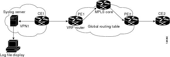
You can configure the VRF Aware System Message Logging feature on a PE router in a Layer 3 MPLS VPN network. The PE router can then send syslog messages through a VRF interface to a syslog server located in the VPN.
Figure 1 shows an MPLS VPN network and the VRF Aware System Message Logging feature configured on a PE router associated with VRF VPN1. The PE router sends log messages through a VRF interface to a syslog server located in VPN1. You can display the messages from the syslog server on a terminal.
Figure 1 MPLS VPN and VRF Aware System Message Logging Configured on a Customer Edge Router
VRF Aware System Message Logging on a Customer Edge Device with VRF-Lite Configured
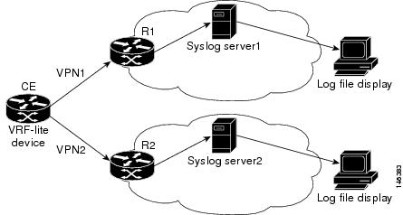
You can configure the VRF Aware System Message Logging feature on a CE device where you have configured the VRF-Lite feature. The CE device can then send syslog messages through a VRF interface to syslog servers in multiple VPNs. The CE device can be either a router or a switch.
Figure 2 shows the VRF Aware System Message Logging feature configured on a VRF-Lite CE device. The CE device can send VRF syslog messages to syslog servers in VPN1 or VPN2 or to servers in both VPN1 and VPN2. You can configure multiple VRFs on a VRF-Lite CE device, and the device can serve many customers.
Figure 2 VRF Aware System Message Logging Configured on a VRF-Lite Customer Edge Device
Message Levels for Logging Commands
Table 1 lists message levels for logging commands that you can use when you configure the VRF Aware System Message Logging feature. Information provided by Table 1 includes keyword level names and numbers, their description, and the associated syslog definitions. You can use either the level keyword name or number with the logging trap level and logging buffered severity-level commands.
How to Configure and Verify VRF Aware System Message Logging
This section contains the following procedures:
•
•
•
•
Configuring a VRF on a Routing Device
Configuring a VRF on a routing device helps provides customer connectivity to a VPN. The routing device can be a PE router connected to an MPLS VPN network or a CE (switch or router) that is configured for VRF-Lite.
SUMMARY STEPS
1.
2.
3.
4.
5.
6.
DETAILED STEPS
Associating a VRF with an Interface
Perform this task to associate a VRF instance with an interface. A VRF must be associated with an interface before you can forward VPN traffic.
Note
After configuring the VRF and associating it with an interface, you can configure the VRF Aware System Message Logging feature on the routing device.
SUMMARY STEPS
1.
2.
3.
4.
5.
6.
DETAILED STEPS
Configuring VRF Aware System Message Logging on a Routing Device
Configure the VRF Aware System Message Logging feature on a routing device so that logging messages can be used to monitor and troubleshoot network traffic connected through VRF instances.
Prerequisites
You must perform the following tasks before you perform this task:
•
•
SUMMARY STEPS
1.
2.
3.
4.
5.
6.
7.
DETAILED STEPS
Step 1
enable
Example:Router> enable
Enables privileged EXEC mode.
•
Step 2
configure terminal
Example:Router# configure terminal
Enters global configuration mode.
Step 3
logging host {ip-address | hostname} [vrf vrf-name]Example:Router(config)# logging host 10.0.150.63 vrf vpn1Specifies a host to receive syslog messages.
•
•
•
Step 4
logging trap level
Example:Router(config)# logging trap debugging
Limits messages logged to the syslog servers based on severity.
•
Step 5
logging facility facility-type
Example:Router(config)# logging facility local6
(Optional) Configures the syslog facility in which error messages are sent.
•
Step 6
logging buffered [buffer-size | severity-level]
Example:Router(config)# logging buffered debugging
(Optional) Limits messages logged to an internal buffer on the router based on severity.
•
•
Step 7
end
Example:Router(config)# end
(Optional) Exits to privileged EXEC mode.
Verifying VRF Aware System Message Logging Operation
Perform this task to verify VRF Aware System Message Logging operation.
SUMMARY STEPS
1.
2.
3.
4.
5.
6.
DETAILED STEPS
Step 1
Use this command to enable privileged EXEC mode. You can also enter this command in user EXEC mode. Enter your password if prompted. For example:
Router> enableRouter#Step 2
Use this command to display the logging configuration for the router and the logging host for a VRF. For example:
Router# show running-config | include logginglogging queue-limit 100logging buffered 100000 debuggingmpls ldp logging neighbor-changeslogging trap debugginglogging facility local6logging host vrf vpn1 10.0.150.63Router#This example shows the configuration of a syslog server in VRF vpn1 with a server host address of 10.0.150.63.
Step 3
Use this command to display the interfaces associated with the VRF that links to a syslog server host. The following example displays a list of VRF interfaces and their associated IP addresses that are configured on the router:
Router# show ip vrf interfacesInterface IP-Address VRF ProtocolFastEthernet0/0 10.0.0.98 vpn1 upEthernet1/4 172.16.0.1 vpn1 upLoopback1 10.66.66.66 vpn1 upStep 4
Use this command to display interface specific configuration information for an interface associated with a VRF. For example:
Router# show running-config interface FastEthernet 0/0Building configuration...Router#...!Current configuration : 116 bytes!interface FastEthernet0/0ip vrf forwarding vpn1ip address 10.0.0.98 255.0.0.0duplex halfno cdp enableendThis example displays configuration information for Fast Ethernet interface 0/0 in VRF vpn1.
Step 5
Use this command to verify that you can reach the syslog server host, the target-ip-address, through the specified VRF. For example:
Router# ping vrf vpn1 10.3.199.1Type escape sequence to abort. Sending 5, 100-byte ICMP Echos to 10.3.199.1, timeout is 2 seconds: .!!!! Success rate is 80 percent (4/5), round-trip min/avg/max = 1/1/1 msIn this example, the syslog server has an IP address of 10.3.199.1 and the VRF is named vpn1. The server is reached successfully four of five times.
Step 6
Use this command to exit privileged EXEC mode. For example:
Router# exitRouter>
Configuration Examples for VRF Aware System Message Logging
This section contains the following configuration examples for the VRF Aware System Message Logging feature:
•
•
•
Configuring a VRF on a Routing Device: Example
The following example shows how to configure a VRF on a routing device:
enableconfigure terminal!ip vrf vpn1rd 100:1route-target both 100:1endAssociating a VRF with an Interface: Example
The following example shows how to associate a VRF with an interface:
enableconfigure terminal!interface FastEthernet 0/0ip vrf forwarding vpn1endConfiguring VRF Aware System Message Logging on a Routing Device: Example
The following example shows how to configure the VRF Aware System Message Logging feature on a routing device. The IP address of the syslog server host is 10.10.150.63 and the VRF is vpn1.
enableconfigure terminal!logging host 10.0.150.63 vrf vpn1logging trap debugginglogging facility local6logging buffered 10000logging buffered debuggingendThe following example shows how to turn off logging to the syslog server:
enableconfigure terminal!no logging 10.0.150.63endAdditional References
The following sections provide references related to configuring the VRF Aware System Message Logging feature.
Related Documents
Concepts and tasks for configuring MPLS VPNs
Basic tasks for troubleshooting your system and the network
Description of commands associated with MPLS and MPLS applications
Concepts and tasks for configuring VRF-lite on a Catalyst 4500 switch
"Configuring VRF-lite" chapter, Catalyst 4500 Series Switch Cisco IOS Software Configuration Guide
Concepts and tasks for configuring VRF Lite on ML-Series Ethernet cards
"Configuring VRF Lite" chapter, Ethernet Card Software Feature and Configuration Guide for the Cisco ONS 15454 SDH, ONS 15454, and ONS 15327
Standards
No new or modified standards are supported by this feature, and support for existing standards has not been modified by this feature.
—
MIBs
RFCs
No new or modified RFCs are supported by this feature, and support for existing RFCs has not been modified by this feature.
—
Technical Assistance
Command Reference
The following commands are introduced or modified in the feature or features documented in this module. For information about these commands, see the Cisco IOS Multiprotocol Label Switching Command Reference at http://www.cisco.com/en/US/docs/ios/mpls/command/reference/mp_book.html. For information about all Cisco IOS commands, use the Command Lookup Tool at http://tools.cisco.com/Support/CLILookup or the Cisco IOS Master Command List, All Releases, at http://www.cisco.com/en/US/docs/ios/mcl/allreleasemcl/all_book.html.
•
Feature Information for VRF Aware System Message Logging
Table 2 lists the release history for this feature.
Not all commands may be available in your Cisco IOS software release. For release information about a specific command, see the command reference documentation.
Use Cisco Feature Navigator to find information about platform support and software image support. Cisco Feature Navigator enables you to determine which Cisco IOS and Catalyst OS software images support a specific software release, feature set, or platform. To access Cisco Feature Navigator, go to http://www.cisco.com/go/cfn. An account on Cisco.com is not required.
Note
Glossary
CE router—customer edge router. A router on the border between a VPN provider and a VPN customer that belongs to the customer.
LSR—label switching router. A device that forwards MPLS packets based on the value of a fixed-length label encapsulated in each packet.
MPLS—Multiprotocol Label Switching. A method for forwarding packets (frames) through a network. It enables routers at the edge of a network to apply labels to packets (frames). ATM switches or existing routers in the network core can switch packets according to the labels with minimal lookup overhead.
MPLS VPN—Multiprotocol Label Switching Virtual Private Network. An IP network infrastructure delivering private network services over a public infrastructure using a Layer 3 backbone. Using MPLS VPNs in a Cisco IOS network provides the capability to deploy and administer scalable Layer 3 VPN backbone services including applications, data hosting network commerce, and telephony services to business customers.
PE router—provider edge router. A router on the border between a VPN provider and a VPN customer that belongs to the provider.
VPN—Virtual Private Network. A group of sites that, as the result of a set of administrative policies, are able to communicate with each other over a shared backbone network. A VPN is a secure IP-based network that shares resources on one or more physical networks. A VPN contains geographically dispersed sites that can communicate securely over a shared backbone. See also MPLS VPN.
VRF—VPN routing and forwarding instance. A VRF consists of an IP routing table, a derived forwarding table, a set of interfaces that use the forwarding table, and a set of rules and routing protocols that determine what goes into the forwarding table. In general, a VRF includes the routing information that defines a customer VPN site that is attached to a PE router.
Cisco and the Cisco Logo are trademarks of Cisco Systems, Inc. and/or its affiliates in the U.S. and other countries. A listing of Cisco's trademarks can be found at www.cisco.com/go/trademarks. Third party trademarks mentioned are the property of their respective owners. The use of the word partner does not imply a partnership relationship between Cisco and any other company. (1005R)
Any Internet Protocol (IP) addresses used in this document are not intended to be actual addresses. Any examples, command display output, and figures included in the document are shown for illustrative purposes only. Any use of actual IP addresses in illustrative content is unintentional and coincidental.
© 2006-2008 Cisco Systems, Inc. All rights reserved.