-
This documentation has been moved
- Part 1 : Basic MPLS
- Part 2 : MPLS label Distribution Protocol
-
Part 3: MPLS Traffic Engineering: Path Calculation and Setup
-
MPLS Traffic Engineering (TE) - Scalability Enhancements
-
MPLS Traffic Engineering - AutoTunnel Mesh Groups
-
MPLS Traffic Engineering - Verbatim Path Support
-
MPLS Traffic Engineering - RSVP Hello State Timer
-
MPLS Traffic Engineering Forwarding Adjacency
-
MPLS Traffic Engineering (TE) - Class-based Tunnel Selection
-
MPLS Traffic Engineering - Interarea Tunnels
-
MPLS Traffic Engineering—Configurable Path Calculation Metric for Tunnels
-
MPLS Traffic Engineering and Enhancements
-
MPLS Traffic Engineering (TE) - IP Explicit Address Exclusion
-
MPLS Traffic Engineering - LSP Attributes
-
MPLS Traffic Engineering—Automatic Bandwidth Adjustment for TE Tunnels
-
MPLS Traffic Engineering—Tunnel Source
-
- Part 4: MPLS Traffic Engineering: DiffServ
- Part 5: MPLS Traffic Engineering: Path, Link, and Node Protection
- Part 6: MPLS Layer 2 VPNs
-
Part 7: MPLS Layer 3 VPNs
-
Configuring MPLS Layer 3 VPNs
-
Assigning an ID Number to a VPN
-
Multi-VRF Selection Using Policy Based Routing (PBR)
-
VRF Aware System Message Logging (Syslog)
-
MPLS VPN—Route Target Rewrite
-
MPLS VPN—Show Running VRF
-
MPLS VPN—VRF CLI for IPv4 and IPv6 VPNs
-
MPLS VPN: VRF Selection Using Policy Based Routing
-
- Part 8: MPLS Layer 3 VPNs: InterAutonomous Systems and Carrier Supporting Carrier
-
Part 9: MPLS Embedded Management and MIBs
-
MPLS LSP Ping/Traceroute for LDP/TE, and LSP Ping for VCCV
-
MPLS Embedded Management—LSP Ping/Traceroute and AToM VCCV
-
MPLS Enhancements to Interfaces MIB
-
MPLS Label Switching Router MIB
-
MPLS Label Distribution Protocol MIB
-
MPLS Label Distribution Protocol MIB Version 8 Upgrade
-
MPLS Traffic Engineering MIB
-
MPLS Traffic Engineering - Fast Reroute MIB
-
MPLS VPN—MIB Support
-
MPLS VPN—SNMP Notifications
-
- Part 10: MPLS High Availability
 Feedback
Table Of Contents
MPLS VPN Carrier Supporting Carrier with BGP
Prerequisites for MPLS VPN CSC with BGP
Restrictions for MPLS VPN CSC with BGP
Information About MPLS VPN CSC with BGP
Benefits of Implementing MPLS VPN CSC
Benefits of Implementing MPLS VPN CSC with BGP
Configuration Options for MPLS VPN CSC with BGP
Customer Carrier Is an ISP with an IP Core
Customer Carrier Is an MPLS Service Provider With or Without VPN Services
How to Configure MPLS VPN CSC with BGP
Identifying the Carrier Supporting Carrier Topology
Configuring the Backbone Carrier Core
Verifying IP Connectivity and LDP Configuration in the CSC Core
Configuring VRFs for CSC-PE Routers
Configuring Multiprotocol BGP for VPN Connectivity in the Backbone Carrier
Configuring the CSC-PE and CSC-CE Routers
Verifying Labels in the CSC-PE Routers
Verifying Labels in the CSC-CE Routers
Configuring the Customer Carrier Network
Verifying IP Connectivity in the Customer Carrier
Configuring a Customer Carrier Core Router as a Route Reflector
Configuring the Customer Site for Hierarchical VPNs
Defining VPNs on PE Routers for Hierarchical VPNs
Configuring BGP Routing Sessions on the PE Routers for Hierarchical VPNs
Verifying Labels in Each PE Router for Hierarchical VPNs
Configuring CE Routers for Hierarchical VPNs
Verifying IP Connectivity in the Customer Site
Configuration Examples for MPLS VPN CSC with BGP
Configuring the Backbone Carrier Core: Examples
Verifying IP Connectivity and LDP Configuration in the CSC Core: Example
Configuring VRFs for CSC-PE Routers: Example
Configuring Multiprotocol BGP for VPN Connectivity in the Backbone Carrier: Example
Configuring the Links Between CSC-PE and CSC-CE Routers: Examples
Configuring the CSC-PE Routers: Examples
Configuring the CSC-CE Routers: Examples
Verifying Labels in the CSC-PE Routers: Examples
Verifying Labels in the CSC-CE Routers: Examples
Configuring the Customer Carrier Network: Examples
Verifying IP Connectivity in the Customer Carrier: Example
Configuring a Customer Carrier Core Router as a Route Reflector: Example
Configuring the Customer Site for Hierarchical VPNs: Examples
Configuring PE Routers for Hierarchical VPNs: Examples
Verifying Labels in Each PE Router for Hierarchical VPNs: Examples
Configuring CE Routers for Hierarchical VPNs: Examples
Verifying IP Connectivity in the Customer Site: Examples
Feature Information for MPLS VPN CSC with BGP
MPLS VPN Carrier Supporting Carrier with BGP
First Published: May 2, 2005Last Updated: February 5, 2009Multiprotocol Label Switching (MPLS) Virtual Private Network (VPN) Carrier Supporting Carrier (CSC) enables one MPLS VPN-based service provider to allow other service providers to use a segment of its backbone network. This module explains how to configure an MPLS VPN CSC network that uses Border Gateway Protocol (BGP) to distribute routes and MPLS labels.
Finding Feature Information
Your software release may not support all the features documented in this module. For the latest feature information and caveats, see the release notes for your platform and software release. To find information about the features documented in this module, and to see a list of the releases in which each feature is supported, see the "Feature Information for MPLS VPN CSC with BGP" section.
Use Cisco Feature Navigator to find information about platform support and Cisco IOS and Catalyst OS software image support. To access Cisco Feature Navigator, go to http://www.cisco.com/go/cfn. An account on Cisco.com is not required.
Contents
•
Prerequisites for MPLS VPN CSC with BGP
•
•
•
•
•
Prerequisites for MPLS VPN CSC with BGP
•
•
Restrictions for MPLS VPN CSC with BGP
On a provider edge (PE) router, you can configure an interface for either BGP with labels or LDP. You cannot enable both types of label distribution on the same interface. If you switch from one protocol to the other, then you must disable the existing protocol on all interfaces before enabling the other protocol.
This feature does not support the following:
•
•
The physical interfaces that connect the BGP speakers must support Cisco Express Forwarding or distributed Cisco Express Forwarding and MPLS.
Information About MPLS VPN CSC with BGP
Before configuring MPLS VPN CSC, you should understand the following concepts:
•
•
•
MPLS VPN CSC Introduction
Carrier supporting carrier is where one service provider allows another service provider to use a segment of its backbone network. The service provider that provides the segment of the backbone network to the other provider is called the backbone carrier. The service provider that uses the segment of the backbone network is called the customer carrier.
A backbone carrier offers Border Gateway Protocol and Multiprotocol Label Switching (BGP/MPLS) VPN services. The customer carrier can be either:
•
•
Benefits of Implementing MPLS VPN CSC
The MPLS VPN CSC network provides the following benefits to service providers who are backbone carriers and to customer carriers.
Benefits to the Backbone Carrier
•
•
•
Benefits to the Customer Carriers
•
•
•
•
Benefits of Implementing MPLS VPN CSC with BGP
You can configure your CSC network to enable BGP to transport routes and MPLS labels between the backbone carrier PE routers and the customer carrier CE routers using multiple paths. The benefits of using BGP to distribute IPv4 routes and MPLS label routes are:
•
•
Configuration Options for MPLS VPN CSC with BGP
The backbone carrier offers BGP and MPLS VPN services. The customer carrier can be either of the following:
•
•
The following sections explain how the backbone and customer carriers distribute IPv4 routes and MPLS labels.
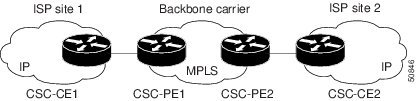
Customer Carrier Is an ISP with an IP Core
Figure 1 shows a network configuration where the customer carrier is an ISP. The customer carrier has two sites, each of which is a point of presence (POP). The customer carrier connects these sites using a VPN service provided by the backbone carrier. The backbone carrier uses MPLS. The ISP sites use IP.
Figure 1 Network Where the Customer Carrier Is an ISP
The links between the CE and PE routers use EBGP to distribute IPv4 routes and MPLS labels. Between the links, the PE routers use multiprotocol IBGP to distribute VPNv4 routes.
Note
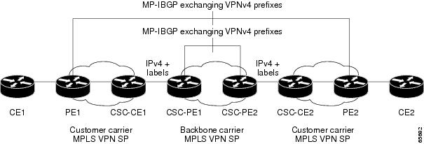
Customer Carrier Is an MPLS Service Provider With or Without VPN Services
Figure 2 shows a network configuration where the backbone carrier and the customer carrier are BGP/MPLS VPN service providers. This is known as hierarchical VPNs. The customer carrier has two sites. Both the backbone carrier and the customer carrier use MPLS in their networks.
Figure 2 Network Where the Customer Carrier Is an MPLS VPN Service Provider
In this configuration, the customer carrier can configure its network in one of the following ways:
•
•
How to Configure MPLS VPN CSC with BGP
This section contains the following tasks:
•
•
•
•
•
Identifying the Carrier Supporting Carrier Topology
Before you configure the MPLS VPN CSC with BGP, you need to identify both the backbone and customer carrier topology.
For hierarchical VPNs, the customer carrier of the MPLS VPN network provides MPLS VPN services to its own customers. In this instance, you need to identify the type of customer carrier as well as the topology of the customer carriers. Hierarchical VPNs require extra configuration steps, which are noted in the configuration sections.
Note
Perform this task to identify the carrier supporting carrier topology.
SUMMARY STEPS
1.
2.
3.
4.
5.
DETAILED STEPS
What to Do Next
Set up your carrier supporting carrier networks with the "Configuring the Backbone Carrier Core" section.
Configuring the Backbone Carrier Core
Configuring the backbone carrier core requires setting up connectivity and routing functions for the CSC core and the CSC-PE routers.
Configuring and verifying the CSC core (backbone carrier) involves the following tasks:
•
•
•
Prerequisites
Before you configure a backbone carrier core, configure the following on the CSC core routers:
•
•
Verifying IP Connectivity and LDP Configuration in the CSC Core
Perform this task to verify IP connectivity and LDP configuration in the CSC core.
SUMMARY STEPS
1.
2.
3.
4.
5.
6.
7.
8.
9.
10.
DETAILED STEPS
Troubleshooting Tips
You can use the ping and trace commands to verify complete MPLS connectivity in the core. You also get useful troubleshooting information from the additional show commands.
Configuring VRFs for CSC-PE Routers
Perform this task to configure VPN forwarding/routing instances (VRFs) for the backbone carrier edge (CSC-PE) routers.
SUMMARY STEPS
1.
2.
3.
4.
5.
6.
7.
8.
9.
10.
DETAILED STEPS
Troubleshooting Tips
Enter a show ip vrf detail command and make sure the MPLS VPN is up and associated with the right interfaces.
Configuring Multiprotocol BGP for VPN Connectivity in the Backbone Carrier
Perform this task to configure Multiprotocol BGP (MP-BGP) connectivity in the backbone carrier.
SUMMARY STEPS
1.
2.
3.
4.
5.
6.
7.
8.
9.
10.
DETAILED STEPS
Troubleshooting Tips
You can enter a show ip bgp neighbor command to verify that the neighbors are up and running. If this command is not successful, enter a debug ip bgp x.x.x.x events command, where x.x.x.x is the IP address of the neighbor.
Configuring the CSC-PE and CSC-CE Routers
Perform the following tasks to configure and verify links between a CSC-PE router and the carrier CSC-CE router for an MPLS VPN CSC network that uses BGP to distribute routes and MPLS labels.
•
•
•
•
Figure 3 shows the configuration for the peering with directly connected interfaces between CSC-PE and CSC-CE routers. This configuration is used as the example in the tasks that follow.
Figure 3 Configuration for Peering with Directly Connected Interfaces Between CSC-PE and CSC-CE Routers
Configuring CSC-PE Routers
Perform this task to configure the CSC-PE routers.
SUMMARY STEPS
1.
2.
3.
4.
5.
6.
7.
8.
9.
10.
DETAILED STEPS
Troubleshooting Tips
Enter a show ip bgp neighbor command to verify that the neighbors are up and running. Make sure you see the following line in the command output under Neighbor capabilities:
IPv4 MPLS Label capability:advertised and receivedConfiguring CSC-CE Routers
Perform this task to configure the CSC-CE routers.
SUMMARY STEPS
1.
2.
3.
4.
5.
6.
7.
8.
ip-address send-label9.
10.
DETAILED STEPS
Verifying Labels in the CSC-PE Routers
Perform this task to verify the labels in the CSC-PE routers.
SUMMARY STEPS
1.
2.
3.
4.
5.
6.
7.
8.
9.
DETAILED STEPS
Verifying Labels in the CSC-CE Routers
Perform this task to verify the labels in the CSC-CE routers.
SUMMARY STEPS
1.
2.
3.
4.
5.
6.
7.
DETAILED STEPS
Configuring the Customer Carrier Network
Perform the following tasks to configure and verify the customer carrier network. This requires setting up connectivity and routing functions for the customer carrier core (P) routers and the customer carrier edge (PE) routers.
•
•
Prerequisites
Before you configure an MPLS VPN CSC network that uses BGP to distribute routes and MPLS labels, you must configure the following on your customer carrier routers:
•
•
•
Note
Verifying IP Connectivity in the Customer Carrier
Perform this task to verify IP connectivity in the customer carrier.
SUMMARY STEPS
1.
2.
3.
4.
5.
DETAILED STEPS
Configuring a Customer Carrier Core Router as a Route Reflector
Perform this task to configure a customer carrier core (P) router as a route reflector of multiprotocol BGP prefixes.
SUMMARY STEPS
1.
2.
3.
4.
5.
6.
7.
8.
9.
DETAILED STEPS
Troubleshooting Tips
By default, neighbors that are defined using the neighbor remote-as command in router configuration mode exchange only unicast address prefixes. For neighbors to exchange other address prefix types, such as multicast and VPNv4, you must also activate neighbors using the neighbor activate command in address family configuration mode, as shown.
Route reflectors and clients (neighbors or internal BGP peer groups) that are defined in router configuration mode using the neighbor route-reflector-client command reflect unicast address prefixes to and from those clients by default. To cause them to reflect prefixes for other address families, such as multicast, define the reflectors and clients in address family configuration mode, using the neighbor route-reflector-client command, as shown.
Configuring the Customer Site for Hierarchical VPNs
Note
Perform the following tasks to configure and verify the customer site for hierarchical VPNs:
•
•
•
•
•
Note
Defining VPNs on PE Routers for Hierarchical VPNs
Perform this task to define VPNs on PE routers.
SUMMARY STEPS
1.
2.
3.
4.
5.
6.
7.
8.
DETAILED STEPS
Configuring BGP Routing Sessions on the PE Routers for Hierarchical VPNs
Perform this task to configure BGP routing sessions on the PE routers for PE-to-CE router communication.
SUMMARY STEPS
1.
2.
3.
4.
5.
6.
7.
DETAILED STEPS
Verifying Labels in Each PE Router for Hierarchical VPNs
Perform this task to verify labels in each PE router for hierarchical VPNs.
SUMMARY STEPS
1.
2.
3.
4.
5.
6.
DETAILED STEPS
Configuring CE Routers for Hierarchical VPNs
Perform this task to configure CE routers for hierarchical VPNs. This configuration is the same as that for an MPLS VPN that is not in a hierarchical topology.
SUMMARY STEPS
1.
2.
3.
4.
5.
6.
7.
8.
9.
10.
DETAILED STEPS
Verifying IP Connectivity in the Customer Site
Perform this task to verify IP connectivity in the customer site.
SUMMARY STEPS
1.
2.
3.
4.
5.
DETAILED STEPS
Configuration Examples for MPLS VPN CSC with BGP
Configuration examples for the MPLS VPN CSC with BGP include the following:
•
•
•
•
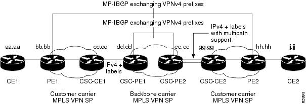
Figure 4 shows a sample CSC topology for exchanging IPv4 routes and MPLS labels. Use this figure as a reference for configuring and verifying carrier supporting carrier routers to exchange IPv4 routes and MPLS labels.
Figure 4 Sample CSC Topology for Exchanging IPv4 Routes and MPLS Labels
Table 1 describes the sample configuration shown in Figure 4.
Table 1 Description of Sample Configuration Shown in Figure 4
CE1 and CE2
Belong to an end customer. CE1 and CE2 routers exchange routes learned from PE routers.
The end customer is purchasing VPN services from a customer carrier.
PE1 and PE2
Part of a customer carrier network that is configured to provide MPLS VPN services. PE1 and PE2 are peering with a VPNv4 IBGP session to form an MPLS VPN network.
CSC-CE1 and CSC-CE2
Part of a customer carrier network. CSC-CE1 and CSC-CE2 routers exchange IPv4 BGP updates with MPLS labels and redistribute PE loopback addressees to and from the IGP (OSPF in this example).
The customer carrier is purchasing carrier supporting carrier VPN services from a backbone carrier.
CSC-PE1 and CSC-PE2
Part of the backbone carrier's network configured to provide carrier supporting carrier VPN services. CSC-PE1 and CSC-PE2 are peering with a VPNv4 IP BGP session to form the MPLS VPN network. In the VRF, CSC-PE1 and CSC-PE2 are peering with the CSC-CE routers, which are configured for carrying MPLS labels with the routes, with an IPv4 EBGP session.
Configuring the Backbone Carrier Core: Examples
Configuration and verification examples for the backbone carrier core included in this section are as follows:
•
•
•
Verifying IP Connectivity and LDP Configuration in the CSC Core: Example
Check that CSC-PE2 is reachable from CSC-PE1 by entering the following command on CSC-CE1:
Router# ping 10.5.5.5Type escape sequence to abort.Sending 5, 100-byte ICMP Echos to 10.5.5.5, timeout is 2 seconds:!!!!!Success rate is 100 percent (5/5), round-trip min/avg/max = 4/4/4 msVerify the path from CSC-PE1 to CSC-PE2 by entering the following command on CSC-CE1:
Router# trace 10.5.5.5Type escape sequence to abort.Tracing the route to 10.5.5.51 10.5.5.5 0 msec 0 msec *Check that CSC-PE router prefixes are in the MPLS forwarding table:
Router# show mpls forwarding-tableLocal Outgoing Prefix or Bytes tag Outgoing Next Hoptag tag or VC Tunnel Id switched interface16 2/nn dd.dd.dd.dd/32 0 AT2/1/0.1 point2point17 16 bb.bb.bb.bb/32[V] 30204 Et1/0 pp.0.0.121 Pop tag cc.cc.cc.cc/32[V] 0 Et1/0 pp.0.0.122 Pop tag nn.0.0.0/8[V] 570 Et1/0 pp.0.0.123 Aggregate pp.0.0.0/8[V] 02 2/nn gg.gg.gg.gg/32[V] 0 AT3/0.1 point2point8 2/nn hh.hh.hh.hh/32[V] 15452 AT3/0.1 point2point29 2/nn qq.0.0.0/8[V] 0 AT3/0.1 point2point30 2/nn ss.0.0.0/8[V] 0 AT3/0.1 point2pointCheck the status of LDP discovery processes in the core:
Router# show mpls ldp discoveryLocal LDP Identifier:ee.ee.ee.ee:0Discovery Sources:Interfaces:ATM2/1/0.1 (ldp): xmit/recvTDP Id: dd.dd.dd.dd:1Check the status of LDP sessions in the core:
Router# show mpls ldp neighborPeer LDP Ident: dd.dd.dd.dd:1; Local LDP Ident ee.ee.ee.ee:1TCP connection: dd.dd.dd.dd.646 - ee.ee.ee.ee.11007State: Oper; Msgs sent/rcvd: 20/21; Downstream on demandUp time: 00:14:56LDP discovery sources:ATM2/1/0.1, Src IP addr: dd.dd.dd.ddCheck the forwarding table (prefixes, next-hops, and interfaces):
Router# show ip cefPrefix Next Hop Interface0.0.0.0/0 drop Null0 (default route handler entry)0.0.0.0/32 receivedd.dd.dd.dd/32 dd.dd.dd.dd ATM2/1/0.1ee.ee.ee.ee/32 receive224.0.0.0/4 drop224.0.0.0/24 receive255.255.255.255/32 receive
Note
Verify that interfaces are configured to use LDP:
Router# show mpls interfaces
Interface IP Tunnel OperationalEthernet0/1 Yes (ldp) No YesDisplay the entire routing table, including host IP address, next hop, interface, and so forth:
Router# show ip route
Codes: C - connected, S - static, I - IGRP, R - RIP, M - mobile, B - BGPD - EIGRP, EX - EIGRP external, O - OSPF, IA - OSPF inter areaN1 - OSPF NSSA external type 1, N2 - OSPF NSSA external type 2E1 - OSPF external type 1, E2 - OSPF external type 2, E - EGPi - IS-IS, L1 - IS-IS level-1, L2 - IS-IS level-2, ia - IS-IS inter area* - candidate default, U - per-user static route, o - ODRGateway of last resort is not setdd.0.0.0/32 is subnetted, 1 subnetsO dd.dd.dd.dd [110/7] via dd.dd.dd.dd, 00:16:42, ATM2/1/0.1ee.0.0.0/32 is subnetted, 1 subnetsC ee.ee.ee.ee is directly connected, Loopback0Configuring VRFs for CSC-PE Routers: Example
The following example shows how to configure a VPN routing and forwarding (VRF) instance for a CSC-PE router:
ip cef distributedip vrf vpn1rd 100:1route target both 100:1!Configuring Multiprotocol BGP for VPN Connectivity in the Backbone Carrier: Example
The following example shows how to configure Multiprotocol BGP (MP-BGP) for VPN connectivity in the backbone carrier:
ip cef distributedip vrf vpn1rd 100:1route target both 100:1hostname csc-pe1!router bgp 100no bgp default ipv4-unicastbgp log-neighbor-changestimers bgp 10 30neighbor ee.ee.ee.ee remote-as 100neighbor ee.ee.ee.ee update-source Loopback0no auto-summary!address-family vpnv4neighbor ee.ee.ee.ee activateneighbor ee.ee.ee.ee send-community extendedbgp dampening 30exit-address-family!router bgp 100. . .! (BGP IPv4 to CSC-CE router from CSC-PE router)!address-family ipv4 vrf vpn1neighbor ss.0.0.2 remote-as 200neighbor ss.0.0.2 activateneighbor ss.0.0.2 as-overrideneighbor ss.0.0.2 advertisement-interval 5neighbor ss.0.0.2 send-labelno auto-summaryno synchronizationbgp dampening 30exit-address-family!Configuring the Links Between CSC-PE and CSC-CE Routers: Examples
This section contains the following examples:
•
•
•
•
Configuring the CSC-PE Routers: Examples
The following example shows how to configure a CSC-PE router:
ip cef!ip vrf vpn1rd 100:1route-target export 100:1route-target import 100:1mpls label protocol ldp!interface Loopback0ip address dd.dd.dd.dd 255.255.255.255!interface Ethernet3/1ip vrf forwarding vpn1ip address pp.0.0.2 255.0.0.0!interface ATM0/1/0no ip addressno ip directed-broadcastno ip route-cache distributedatm clock INTERNALno atm enable-ilmi-trapno atm ilmi-keepalive!interface ATM0/1/0.1 mplsip unnumbered Loopback0no ip directed-broadcastno atm enable-ilmi-trapmpls label protocol ldpmpls atm vpi 2-5mpls ip!router ospf 100log-adjacency-changesauto-cost reference-bandwidth 1000redistribute connected subnetspassive-interface Ethernet3/1network dd.dd.dd.dd 0.0.0.0 area 100!router bgp 100no bgp default ipv4-unicastbgp log-neighbor-changestimers bgp 10 30neighbor ee.ee.ee.ee remote-as 100neighbor ee.ee.ee.ee update-source Loopback0!address-family vpnv4 !VPNv4 session with CSC-PE2neighbor ee.ee.ee.ee activateneighbor ee.ee.ee.ee send-community extendedbgp dampening 30exit-address-family!address-family ipv4 vrf vpn1neighbor pp.0.0.1 remote-as 200neighbor pp.0.0.1 activateneighbor pp.0.0.1 as-overrideneighbor pp.0.0.1 advertisement-interval 5neighbor pp.0.0.1 send-labelno auto-summaryno synchronizationbgp dampening 30exit-address-familyConfiguring the CSC-CE Routers: Examples
The following example shows how to configure a CSC-CE router:
ip cef!mpls label protocol ldp!interface Loopback0ip address cc.cc.cc.cc 255.255.255.255!interface Ethernet3/0ip address pp.0.0.1 255.0.0.0!interface Ethernet4/0ip address nn.0.0.2 255.0.0.0no ip directed-broadcastno ip mroute-cachempls label protocol ldpmpls ip!router ospf 200log-adjacency-changesauto-cost reference-bandwidth 1000redistribute connected subnets !Exchange routesredistribute bgp 200 metric 3 subnets !learned from PE1passive-interface ATM1/0passive-interface Ethernet3/0network cc.cc.cc.cc 0.0.0.0 area 200network nn.0.0.0 0.255.255.255 area 200!router bgp 200no bgp default ipv4-unicastbgp log-neighbor-changestimers bgp 10 30neighbor pp.0.0.2 remote-as 100neighbor pp.0.0.2 update-source Ethernet3/0no auto-summary!address-family ipv4redistribute connectedredistribute ospf 200 metric 4 match internalneighbor pp.0.0.2 activateneighbor pp.0.0.2 send-labelno auto-summaryno synchronizationbgp dampening 30exit-address-familyVerifying Labels in the CSC-PE Routers: Examples
The following examples show how to verify the configurations of the CSC-PE routers.
Verify that the BGP session is up and running between the CSC-PE router and the CSC-CE router. Check the data in the State/PfxRcd column to verify that prefixes are learned during each session.
Router# show ip bgp vpnv4 all summaryBBGP router identifier 10.5.5.5, local AS number 100BGP table version is 52, main routing table version 5212 network entries and 13 paths using 2232 bytes of memory6 BGP path attribute entries using 336 bytes of memory1 BGP AS-PATH entries using 24 bytes of memory1 BGP extended community entries using 24 bytes of memory0 BGP route-map cache entries using 0 bytes of memory0 BGP filter-list cache entries using 0 bytes of memoryDampening enabled. 0 history paths, 0 dampened pathsBGP activity 16/4 prefixes, 27/14 paths, scan interval 5 secsNeighbor V AS MsgRcvd MsgSent TblVer InQ OutQ Up/Down State/PfxRcd10.5.5.5 4 100 7685 7686 52 0 0 21:17:04 610.0.0.2 4 200 7676 7678 52 0 0 21:16:43 7Verify that the MPLS interfaces are up and running, and that LDP-enabled interfaces show that LDP is up and running. LDP is turned off on the VRF because EBGP distributes the labels.
Router# show mpls interfaces allInterface IP Tunnel OperationalGigabitEthernet6/0 Yes (ldp) No YesVRF vpn1:Ethernet3/1 No No YesVerify that the prefix for the local PE router is in the routing table of the CSC-PE router:
Router# show ip route vrf vpn2 10.5.5.5Routing entry for 10.5.5.5/32Known via "bgp 100", distance 20, metric 4Tag 200, type externalLast update from pp.0.0.2 21:28:39 agoRouting Descriptor Blocks:* pp.0.0.2, from pp.0.0.2, 21:28:39 agoRoute metric is 4, traffic share count is 1AS Hops 1, BGP network version 0Verify that the prefix for the remote PE router is in the routing table of the CSC-PE router:
Router# show ip route vrf vpn2 10.5.5.5Routing entry for 10.5.5.5/32Known via "bgp 100", distance 200, metric 4Tag 200, type internalLast update from 10.1.0.0 21:27:39 agoRouting Descriptor Blocks:* 10.1.0.0 (Default-IP-Routing-Table), from 10.1.0.0, 21:27:39 agoRoute metric is 4, traffic share count is 1AS Hops 1, BGP network version 0Verify that the prefixes for the customer carrier MPLS VPN service provider networks are in the BGP table, and have appropriate labels:
Router# show ip bgp vpnv4 vrf vpn2 labelsNetwork Next Hop In label/Out labelRoute Distinguisher: 100:1 (vpn1)cc.cc.cc.cc/32 pp.0.0.2 22/imp-nullbb.bb.bb.bb/32 pp.0.0.2 27/20hh.hh.hh.hh/32 ee.ee.ee.ee 34/35gg.gg.gg.gg/32 ee.ee.ee.ee 30/30nn.0.0.0 pp.0.0.2 23/imp-nullss.0.0.0 ee.ee.ee.ee 33/34pp.0.0.0 pp.0.0.2 25/aggregate(vpn1)Verify that the prefix of the PE router in the local customer carrier MPLS VPN service provider is in the Cisco Express Forwarding table:
Router# show ip cef vrf vpn2 10.1.0.010.1.0.0/32, version 19, cached adjacency pp.0.0.20 packets, 0 bytestag information setlocal tag: 27fast tag rewrite with Et3/1, pp.0.0.2, tags imposed {20}via pp.0.0.2, 0 dependencies, recursivenext hop pp.0.0.2, Ethernet3/1 via pp.0.0.2/32valid cached adjacencytag rewrite with Et3/1, pp.0.0.2, tags imposed {20}Router# show ip cef vrf vpn2 10.1.0.0 detail10.1.0.0/32, version 19, cached adjacency pp.0.0.20 packets, 0 bytestag information setlocal tag: 27fast tag rewrite with Et3/1, pp.0.0.2, tags imposed {20}via pp.0.0.2, 0 dependencies, recursivenext hop pp.0.0.2, Ethernet3/1 via pp.0.0.2/32valid cached adjacencytag rewrite with Et3/1, pp.0.0.2, tags imposed {20}Verify that the prefix of the PE router in the local customer carrier MPLS VPN service provider is in the MPLS forwarding table:
Router# show mpls forwarding-table vrf vpn2 10.1.0.0Local Outgoing Prefix Bytes tag Outgoing Next Hoptag tag or VC or Tunnel Id switched interface27 20 10.1.0.0/32[V] 958048 Et3/1 pp.0.0.2Router# show mpls forwarding-table vrf vpn2 10.1.0.0 detailLocal Outgoing Prefix Bytes tag Outgoing Next Hoptag tag or VC or Tunnel Id switched interface27 20 10.1.0.0/32[V] 958125 Et3/1 pp.0.0.2MAC/Encaps=14/18, MTU=1500, Tag Stack{20}00B04A74A05400B0C26E10558847 00014000VPN route: vpn1No output feature configuredPer-packet load-sharing, slots: 0 1 2 3 4 5 6 7 8 9 10 11 12 13 14 15Verify that the prefix of the PE router in the remote customer carrier MPLS VPN service provider is in the Cisco Express Forwarding table:
Router# show ip cef vrf vpn2 10.3.0.010.3.0.0/32, version 25, cached adjacency rr.0.0.20 packets, 0 bytestag information setlocal tag: 34fast tag rewrite with Gi6/0, rr.0.0.2, tags imposed {35}via ee.ee.ee.ee, 0 dependencies, recursivenext hop rr.0.0.2, GigabitEthernet6/0 via ee.ee.ee.ee/32valid cached adjacencytag rewrite with Gi6/0, rr.0.0.2, tags imposed {35}Router# show ip cef vrf vpn2 10.3.0.0 detailhh.hh.hh.hh/32, version 25, cached adjacency rr.0.0.20 packets, 0 bytestag information setlocal tag: 34fast tag rewrite with Gi6/0, rr.0.0.2, tags imposed {35}via ee.ee.ee.ee, 0 dependencies, recursivenext hop rr.0.0.2, GigabitEthernet6/0 via ee.ee.ee.ee/32valid cached adjacencytag rewrite with Gi6/0, rr.0.0.2, tags imposed {35}Verify that the prefix of the PE router in the remote customer carrier MPLS VPN service provider is in the MPLS forwarding table:
Router# show mpls forwarding-table vrf vpn2 10.3.0.0Local Outgoing Prefix Bytes tag Outgoing Next Hoptag tag or VC or Tunnel Id switched interface34 35 hh.hh.hh.hh/32[V] 139034 Gi6/0 rr.0.0.2Router# show mpls forwarding-table vrf vpn2 10.3.0.0 detailLocal Outgoing Prefix Bytes tag Outgoing Next Hoptag tag or VC or Tunnel Id switched interface34 35 hh.hh.hh.hh/32[V] 139034 Gi6/0 rr.0.0.2MAC/Encaps=14/18, MTU=1500, Tag Stack{35}00B0C26E447000B0C26E10A88847 00023000VPN route: vpn1No output feature configuredPer-packet load-sharing, slots: 0 1 2 3 4 5 6 7 8 9 10 11 12 13 14 15Verifying Labels in the CSC-CE Routers: Examples
The following examples show how to verify the configurations of the CSC-CE routers.
Verify that the BGP session is up and running:
Router# show ip bgp summaryBGP router identifier cc.cc.cc.cc, local AS number 200BGP table version is 35, main routing table version 3514 network entries and 14 paths using 2030 bytes of memory3 BGP path attribute entries using 168 bytes of memory1 BGP AS-PATH entries using 24 bytes of memory0 BGP route-map cache entries using 0 bytes of memory0 BGP filter-list cache entries using 0 bytes of memoryDampening enabled. 1 history paths, 0 dampened pathsBGP activity 17/67 prefixes, 29/15 paths, scan interval 60 secsNeighbor V AS MsgRcvd MsgSent TblVer InQ OutQ Up/Down State/PfxRcdpp.0.0.1 4 100 7615 7613 35 0 0 21:06:19 5Verify that the loopback address of the local PE router is in the routing table:
Router# show ip route 10.1.0.0Routing entry for 10.1.0.0/32Known via "ospf 200", distance 110, metric 101, type intra areaRedistributing via bgp 200Advertised by bgp 200 metric 4 match internalLast update from nn.0.0.1 on Ethernet4/0, 00:34:08 agoRouting Descriptor Blocks:* nn.0.0.1, from bb.bb.bb.bb, 00:34:08 ago, via Ethernet4/0Route metric is 101, traffic share count is 1Verify that the loopback address of the remote PE router is in the routing table:
Router# show ip route 10.5.5.5Routing entry for 10.5.5.5/32Known via "bgp 200", distance 20, metric 0Tag 100, type externalRedistributing via ospf 200Advertised by ospf 200 metric 3 subnetsLast update from pp.0.0.1 00:45:16 agoRouting Descriptor Blocks:* pp.0.0.1, from pp.0.0.1, 00:45:16 agoRoute metric is 0, traffic share count is 1AS Hops 2, BGP network version 0Verify that the prefix of the local PE router is in the MPLS LDP bindings:
Router# show mpls ldp bindings 10.1.0.0 255.255.255.255tib entry: 10.1.0.0/32, rev 20local binding: tag: 20remote binding: tsr: 10.1.0.0:0, tag: imp-nullVerify that the prefix of the local PE router is in the Cisco Express Forwarding table:
Router# show ip cef 10.1.0.010.1.0.0/32, version 46, cached adjacency nn.0.0.10 packets, 0 bytestag information setlocal tag: 20via nn.0.0.1, Ethernet4/0, 0 dependenciesnext hop nn.0.0.1, Ethernet4/0unresolvedvalid cached adjacencytag rewrite with Et4/0, nn.0.0.1, tags imposed {}Verify that the prefix of the local PE router is in the MPLS forwarding table:
Router# show mpls forwarding-table 10.1.0.0Local Outgoing Prefix Bytes tag Outgoing Next Hoptag tag or VC or Tunnel Id switched interface20 Pop tag bb.bb.bb.bb/32 893397 Et4/0 nn.0.0.1Router# show mpls forwarding-table 10.1.0.0 detailLocal Outgoing Prefix Bytes tag Outgoing Next Hoptag tag or VC or Tunnel Id switched interface20 Pop tag bb.bb.bb.bb/32 893524 Et4/0 nn.0.0.1MAC/Encaps=14/14, MTU=1504, Tag Stack{}00074F83685400B04A74A0708847No output feature configuredPer-packet load-sharing, slots: 0 1 2 3 4 5 6 7 8 9 10 11 12 13 14 15Verify that the BGP routing table contains labels for prefixes in the customer carrier MPLS VPN service provider networks:
Router# show ip bgp labelsNetwork Next Hop In Label/Out Labelcc.cc.cc.cc/32 0.0.0.0 imp-null/exp-nullbb.bb.bb.bb/32 nn.0.0.1 20/exp-nullhh.hh.hh.hh/32 pp.0.0.1 26/34gg.gg.gg.gg/32 pp.0.0.1 23/30nn.0.0.0 0.0.0.0 imp-null/exp-nullss.0.0.0 pp.0.0.1 25/33pp.0.0.0 0.0.0.0 imp-null/exp-nullpp.0.0.1/32 0.0.0.0 16/exp-nullVerify that the prefix of the remote PE router is in the Cisco Express Forwarding table:
Router# show ip cef 10.5.5.510.5.5.5/32, version 54, cached adjacency pp.0.0.10 packets, 0 bytestag information setlocal tag: 26fast tag rewrite with Et3/0, pp.0.0.1, tags imposed {34}via pp.0.0.1, 0 dependencies, recursivenext hop pp.0.0.1, Ethernet3/0 via pp.0.0.1/32valid cached adjacencytag rewrite with Et3/0, pp.0.0.1, tags imposed {34}Verify that the prefix of the remote PE router is in the MPLS forwarding table:
Router# show mpls forwarding-table 10.5.5.5Local Outgoing Prefix Bytes tag Outgoing Next Hoptag tag or VC or Tunnel Id switched interface26 34 hh.hh.hh.hh/32 81786 Et3/0 pp.0.0.1Router# show mpls forwarding-table 10.5.5.5 detailLocal Outgoing Prefix Bytes tag Outgoing Next Hoptag tag or VC or Tunnel Id switched interface26 34 hh.hh.hh.hh/32 81863 Et3/0 pp.0.0.1MAC/Encaps=14/18, MTU=1500, Tag Stack{34}00B0C26E105500B04A74A0548847 00022000No output feature configuredPer-packet load-sharing, slots: 0 1 2 3 4 5 6 7 8 9 10 11 12 13 14 15Configuring the Customer Carrier Network: Examples
Customer carrier configuration and verification examples in this section include:
•
•
Verifying IP Connectivity in the Customer Carrier: Example
Verify the connectivity from one customer carrier core router to another (from CE1 to CE2) by entering the following command:
Router# ping 10.2.0.0Type escape sequence to abort.Sending 5, 100-byte ICMP Echos to jj.jj.jj.jj, timeout is 2 seconds:!!!!!Success rate is 100 percent (5/5), round-trip min/avg/max = 8/9/12 msVerify the path that a packet goes through on its way to its final destination from CE1 to CE2:
Router# trace 10.2.0.0Type escape sequence to abort.Tracing the route to 10.2.0.01 mm.0.0.2 0 msec 0 msec 4 msec2 nn.0.0.2 [MPLS: Labels 20/21 Exp 0] 8 msec 8 msec 12 msec3 pp.0.0.2 [MPLS: Labels 28/21 Exp 0] 8 msec 8 msec 12 msec4 ss.0.0.1 [MPLS: Labels 17/21 Exp 0] 8 msec 8 msec 12 msec5 ss.0.0.2 [MPLS: Labels 16/21 Exp 0] 8 msec 8 msec 12 msec6 tt.0.0.1 [AS 200] [MPLS: Label 21 Exp 0] 8 msec 8 msec 8 msec7 tt.0.0.2 [AS 200] 8 msec 4 msec *Verify the path that a packet goes through on its way to its final destination from CE2 to CE1:
Router# trace 10.1.0.0Type escape sequence to abort.Tracing the route to 10.1.0.01 tt.0.0.1 0 msec 0 msec 0 msec2 qq.0.0.2 [MPLS: Labels 18/21 Exp 0] 8 msec 12 msec 12 msec3 ss.0.0.1 [MPLS: Labels 28/21 Exp 0] 8 msec 8 msec 8 msec4 pp.0.0.2 [MPLS: Labels 17/21 Exp 0] 12 msec 8 msec 8 msec5 pp.0.0.1 [MPLS: Labels 16/21 Exp 0] 12 msec 12 msec 8 msec6 mm.0.0.2 [AS 200] [MPLS: Label 21 Exp 0] 12 msec 8 msec 12 msec7 mm.0.0.1 [AS 200] 4 msec 4 msec *Configuring a Customer Carrier Core Router as a Route Reflector: Example
The following example shows how to use an address family to configure internal BGP peer 10.1.1.1 as a route-reflector client for both unicast and multicast prefixes:
router bgp 200address-family vpnv4neighbor 10.1.1.1 activateneighbor 10.1.1.1 route-reflector-clientrouter bgp 100address-family vpnv4neighbor xx.xx.xx.xx activateneighbor xx.xx.xx.xx route-reflector-client! xx.xx.xx,xx is a PE routerneighbor xx.xx.xx.xx send-community extendedexit address-family! You need to configure your peer BGP neighbor.Configuring the Customer Site for Hierarchical VPNs: Examples
This section contains the following configuration and verification examples for the customer site:
•
•
•
•
Configuring PE Routers for Hierarchical VPNs: Examples
This example shows how to configure a PE router:
ip cef!ip vrf vpn2rd 200:1route-target export 200:1route-target import 200:1mpls label protocol ldp!interface Loopback0ip address bb.bb.bb.bb 255.255.255.255!interface Ethernet3/0ip address nn.0.0.1 255.0.0.0no ip directed-broadcastno ip mroute-cachempls label protocol ldpmpls ip!interface Ethernet3/3ip vrf forwarding vpn2ip address mm.0.0.2 255.0.0.0no ip directed-broadcastno ip mroute-cache!router ospf 200log-adjacency-changesauto-cost reference-bandwidth 1000redistribute connected subnetspassive-interface Ethernet3/3network bb.bb.bb.bb 0.0.0.0 area 200network nn.0.0.0 0.255.255.255 area 200!router bgp 200no bgp default ipv4-unicastbgp log-neighbor-changestimers bgp 10 30neighbor hh.hh.hh.hh remote-as 200neighbor hh.hh.hh.hh update-source Loopback0!address-family vpnv4 !VPNv4 session with PE2neighbor hh.hh.hh.hh activateneighbor hh.hh.hh.hh send-community extendedbgp dampening 30exit-address-family!address-family ipv4 vrf vpn2neighbor mm.0.0.1 remote-as 300neighbor mm.0.0.1 activateneighbor mm.0.0.1 as-overrideneighbor mm.0.0.1 advertisement-interval 5no auto-summaryno synchronizationbgp dampening 30exit-address-familyVerifying Labels in Each PE Router for Hierarchical VPNs: Examples
The following examples show how to verify the configuration of PE router in hierarchical VPNs.
Verify that the loopback address of the local CE router is in the routing table of the PE1 router:
Router# show ip route vrf vpn2 10.2.2.2Routing entry for 10.2.2.2/32Known via "bgp 200", distance 20, metric 0Tag 300, type externalLast update from mm.0.0.2 20:36:59 agoRouting Descriptor Blocks:* mm.0.0.2, from mm.0.0.2, 20:36:59 agoRoute metric is 0, traffic share count is 1AS Hops 1, BGP network version 0Verify that the prefix for the local CE router is in the MPLS forwarding table, and that the prefix is untagged:
Router# show mpls forwarding-table vrf vpn2 10.2.2.2Local Outgoing Prefix Bytes tag Outgoing Next Hoptag tag or VC or Tunnel Id switched interface23 Untagged aa.aa.aa.aa/32[V] 0 Et3/3 mm.0.0.2Verify that the prefix of the remote PE router is in the Cisco Express Forwarding table:
Router# show ip cef 10.5.5.510.5.5.5/32, version 31, cached adjacency nn.0.0.20 packets, 0 bytestag information setlocal tag: 31fast tag rewrite with Et3/0, nn.0.0.2, tags imposed {26}via nn.0.0.2, Ethernet3/0, 2 dependenciesnext hop nn.0.0.2, Ethernet3/0unresolvedvalid cached adjacencytag rewrite with Et3/0, nn.0.0.2, tags imposed {26}Verify that the loopback address of the remote CE router is in the routing table:
Router# show ip route vrf vpn2 10.2.0.0Routing entry for 10.2.0.0/32Known via "bgp 200", distance 200, metric 0Tag 300, type internalLast update from hh.hh.hh.hh 20:38:49 agoRouting Descriptor Blocks:* hh.hh.hh.hh (Default-IP-Routing-Table), from hh.hh.hh.hh, 20:38:49 agoRoute metric is 0, traffic share count is 1AS Hops 1, BGP network version 0Verify that the prefix of the remote CE router is in the MPLS forwarding table, and that an outgoing interface exists:
Router# show mpls forwarding-table vrf vpn2 10.2.0.0Local Outgoing Prefix Bytes tag Outgoing Next Hoptag tag or VC or Tunnel Id switched interfaceNone 26 jj.jj.jj.jj/32 0 Et3/0 nn.0.0.2Verify that the prefix of the remote CE router is in the Cisco Express Forwarding table:
Router# show ip cef vrf vpn2 10.2.0.010.2.0.0/32, version 12, cached adjacency nn.0.0.20 packets, 0 bytestag information setlocal tag: VPN route headfast tag rewrite with Et3/0, nn.0.0.2, tags imposed {26 32}via hh.hh.hh.hh, 0 dependencies, recursivenext hop nn.0.0.2, Ethernet3/0 via hh.hh.hh.hh/32valid cached adjacencytag rewrite with Et3/0, nn.0.0.2, tags imposed {26 32}Verify that the prefix of the local PE router is in the Cisco Express Forwarding table:
Router# show ip cef 10.1.0.010.1.0.0/32, version 9, connected, receivetag information setlocal tag: implicit-nullConfiguring CE Routers for Hierarchical VPNs: Examples
The following example shows how to configure a CE router:
ip cef distributedinterface Loopback0ip address 10.3.0.0 255.255.255.255!interface FastEthernet0/3/3ip address mm.0.0.1 255.0.0.0!router bgp 300no synchronizationbgp log-neighbor-changestimers bgp 10 30redistribute connected !Redistributing routes into BGPneighbor mm.0.0.2 remote-as 200 !to send to PE1neighbor mm.0.0.2 advertisement-interval 5no auto-summaryVerifying IP Connectivity in the Customer Site: Examples
The following examples show how to verify IP connectivity at the customer site.
Verify that the loopback address of the remote CE router, learned from the PE router, is in the routing table of the local router:
Router# show ip route 10.2.0.0Routing entry for 10.2.0.0/32Known via "bgp 300", distance 20, metric 0Tag 200, type externalRedistributing via ospf 300Advertised by ospf 300 subnetsLast update from mm.0.0.1 20:29:35 agoRouting Descriptor Blocks:* mm.0.0.1, from mm.0.0.1, 20:29:35 agoRoute metric is 0, traffic share count is 1AS Hops 2Additional References
The following sections provide information related to MPLS VPNs.
Related Documents
Standards
No new or modified standards are supported by this feature, and support for existing standards has not been modified by this feature.
—
MIBs
RFCs
Technical Assistance
Command Reference
This feature uses no new or modified commands.
Feature Information for MPLS VPN CSC with BGP
Table 2 lists the release history for this feature.
Not all commands may be available in your Cisco IOS software release. For release information about a specific command, see the command reference documentation.
Use Cisco Feature Navigator to find information about platform support and software image support. Cisco Feature Navigator enables you to determine which Cisco IOS and Catalyst OS software images support a specific software release, feature set, or platform. To access Cisco Feature Navigator, go to http://www.cisco.com/go/cfn. An account on Cisco.com is not required.
Note
Glossary
ASBR— Autonomous System Boundary router. A router that connects one autonomous system to another.
BGP—Border Gateway Protocol. An interdomain routing protocol designed to provide loop-free routing between separate routing domains that contain independent routing policies (autonomous systems).
CE router—customer edge router. A router that is part of a customer network and that interfaces to a provider edge (PE) router. In this document, the CE router sits on the edge of the customer carrier network.
edge router—A router that is at the edge of the network. It defines the boundary of the MPLS network. It receives and transmits packets. Also referred to as edge label switch router and label edge router.
LDP—Label Distribution Protocol. A standard protocol between MPLS-enabled routers to negotiate the labels (addresses) used to forward packets.
MPLS—Multiprotocol Label Switching. Switching method that forwards IP traffic using a label. This label instructs the routers and the switches in the network where to forward the packets based on preestablished IP routing information.
PE router—provider edge router. A router, at the edge of a service provider's network, that interfaces to CE routers.
VPN—Virtual Private Network. A network that enables IP traffic to use tunneling to travel securely over a public TCP/IP network.
Cisco and the Cisco Logo are trademarks of Cisco Systems, Inc. and/or its affiliates in the U.S. and other countries. A listing of Cisco's trademarks can be found at www.cisco.com/go/trademarks. Third party trademarks mentioned are the property of their respective owners. The use of the word partner does not imply a partnership relationship between Cisco and any other company. (1005R)
Any Internet Protocol (IP) addresses used in this document are not intended to be actual addresses. Any examples, command display output, and figures included in the document are shown for illustrative purposes only. Any use of actual IP addresses in illustrative content is unintentional and coincidental.
© 2005—2009 Cisco Systems, Inc. All rights reserved.