-
This documentation has been moved
- Part 1 : Basic MPLS
- Part 2 : MPLS label Distribution Protocol
-
Part 3: MPLS Traffic Engineering: Path Calculation and Setup
-
MPLS Traffic Engineering (TE) - Scalability Enhancements
-
MPLS Traffic Engineering - AutoTunnel Mesh Groups
-
MPLS Traffic Engineering - Verbatim Path Support
-
MPLS Traffic Engineering - RSVP Hello State Timer
-
MPLS Traffic Engineering Forwarding Adjacency
-
MPLS Traffic Engineering (TE) - Class-based Tunnel Selection
-
MPLS Traffic Engineering - Interarea Tunnels
-
MPLS Traffic Engineering—Configurable Path Calculation Metric for Tunnels
-
MPLS Traffic Engineering and Enhancements
-
MPLS Traffic Engineering (TE) - IP Explicit Address Exclusion
-
MPLS Traffic Engineering - LSP Attributes
-
MPLS Traffic Engineering—Automatic Bandwidth Adjustment for TE Tunnels
-
MPLS Traffic Engineering—Tunnel Source
-
- Part 4: MPLS Traffic Engineering: DiffServ
- Part 5: MPLS Traffic Engineering: Path, Link, and Node Protection
- Part 6: MPLS Layer 2 VPNs
-
Part 7: MPLS Layer 3 VPNs
-
Configuring MPLS Layer 3 VPNs
-
Assigning an ID Number to a VPN
-
Multi-VRF Selection Using Policy Based Routing (PBR)
-
VRF Aware System Message Logging (Syslog)
-
MPLS VPN—Route Target Rewrite
-
MPLS VPN—Show Running VRF
-
MPLS VPN—VRF CLI for IPv4 and IPv6 VPNs
-
MPLS VPN: VRF Selection Using Policy Based Routing
-
- Part 8: MPLS Layer 3 VPNs: InterAutonomous Systems and Carrier Supporting Carrier
-
Part 9: MPLS Embedded Management and MIBs
-
MPLS LSP Ping/Traceroute for LDP/TE, and LSP Ping for VCCV
-
MPLS Embedded Management—LSP Ping/Traceroute and AToM VCCV
-
MPLS Enhancements to Interfaces MIB
-
MPLS Label Switching Router MIB
-
MPLS Label Distribution Protocol MIB
-
MPLS Label Distribution Protocol MIB Version 8 Upgrade
-
MPLS Traffic Engineering MIB
-
MPLS Traffic Engineering - Fast Reroute MIB
-
MPLS VPN—MIB Support
-
MPLS VPN—SNMP Notifications
-
- Part 10: MPLS High Availability
 Feedback
Table Of Contents
Prerequisites for MPLS VPN—MIB Support
Restrictions for MPLS VPN—MIB Support
Information About MPLS VPN—MIB Support
Capabilities Supported by PPVPN-MPLS-VPN MIB
Functional Structure of the PPVPN-MPLS-VPN MIB
Supported Objects in PPVPN-MPLS-VPN MIB
Unsupported Objects in PPVPN-MPLS-VPN MIB
How to Configure MPLS VPN—MIB Support
Configuring the SNMP Community
Configuring the Router to Send SNMP Traps
Configuring Threshold Values for MPLS VPN—SNMP Notifications
Configuration Examples for MPLS VPN—MIB Support
Configuring the SNMP Community: Examples
Configuring the Router to Send SNMP Traps: Example
Configuring Threshold Values for MPLS VPN—SNMP Notifications: Examples
Feature Information for MPLS VPN—MIB Support
MPLS VPN—MIB Support
First Published: March 18, 2002Last Updated: August 26, 2008This document describes the Simple Network Management Protocol (SNMP) agent support in Cisco IOS software for Multiprotocol Label Switching (MPLS) Virtual Private Network (VPN) management, as implemented in the draft MPLS/BGP Virtual Private Network Management Information Base Using SMIv2 (draft-ietf-ppvpn-mpls-vpn-mib-05.txt). This document also describes the cMplsNumVrfRouteMaxThreshCleared notification, which is implemented as part of the proprietary MIB CISCO-IETF-PPVNP-MPLS-VPN-MIB.
Finding Feature Information
Your software release may not support all the features documented in this module. For the latest feature information and caveats, see the release notes for your platform and software release. To find information about the features documented in this module, and to see a list of the releases in which each feature is supported, see the "Feature Information for MPLS VPN—MIB Support" section.
Use Cisco Feature Navigator to find information about platform support and Cisco IOS and Catalyst OS software image support. To access Cisco Feature Navigator, go to http://www.cisco.com/go/cfn. An account on Cisco.com is not required.
Contents
•
Prerequisites for MPLS VPN—MIB Support
•
•
•
•
•
Prerequisites for MPLS VPN—MIB Support
The MPLS VPN MIB agent requires the following:
•
•
•
•
Restrictions for MPLS VPN—MIB Support
The following restrictions apply to the PPVPN-MPLS-VPN MIB:
•
•
Information About MPLS VPN—MIB Support
This section contains the following topics:
•
•
•
•
MPLS VPN Overview
The MPLS VPN technology allows service providers to offer intranet and extranet VPN services that directly connect their customers' remote offices to a public network with the same security and service levels that a private network offers. Each VPN is associated with one or more VPN routing and forwarding (VRF) instances. A VRF is created for each VPN defined on a router and contains most of the information needed to manage and monitor MPLS VPNs: an IP routing table, a derived Cisco Express Forwarding table, a set of interfaces that use this forwarding table, and a set of rules and routing protocol parameters that control the information that is included in the routing table.
MPLS VPN MIB Overview
The Provider-Provisioned VPN (PPVPN)-MPLS-VPN MIB provides access to MPLS VRF information, and interfaces included in the VRF, and other configuration and monitoring information.
The PPVPN-MPLS-VPN MIB provides the following benefits:
•
•
•
•
•
•
•
This document also describes the CISCO-IETF-PPVPN-MPLS-VPN-MIB, which contains the cMplsNumVrfRouteMaxThreshCleared notification.
MPLS VPN MIB and the IETF
SNMP agent code operating with the PPVPN-MPLS-VPN MIB enables a standardized, SNMP-based approach to managing MPLS VPNs in Cisco IOS software.
The PPVPN-MPLS-VPN MIB is based on the Internet Engineering Task Force draft MIB specification draft-ietf-ppvpn-mpls-vpn-mib-05.txt, which includes objects describing features that support MPLS VPN events. This IETF draft MIB, which undergoes revisions from time to time, is becoming a standard. Accordingly, the Cisco implementation of the PPVPN-MPLS-VPN MIB is expected to track the evolution of the IETF draft MIB, and may change accordingly.
Some slight differences between the IETF draft MIB and the actual implementation of MPLS VPNs within Cisco IOS software require some minor translations between the PPVPN-MPLS-VPN MIB and the internal data structures of Cisco IOS software. These translations are accomplished by means of the SNMP agent code. Also, while running as a low priority process, the SNMP agent provides a management interface to Cisco IOS software. SNMP adds little overhead on the normal functions of the device.
The SNMP objects defined in the PPVPN-MPLS-VPN MIB can be viewed by any standard SNMP utility. The network administrator can retrieve information in the PPVPN-MPLS-VPN MIB using standard SNMP get and getnext operations for SNMP v1, v2, and v3.
All PPVPN-MPLS-VPN MIB objects are based on the IETF draft MIB; thus, no Cisco-specific SNMP application is required to support the functions and operations pertaining to the PPVPN-MPLS-VPN MIB features.
Capabilities Supported by PPVPN-MPLS-VPN MIB
The PPVPN-MPLS-VPN MIB provides you with the ability to do the following:
•
•
•
•
•
•
•
Functional Structure of the PPVPN-MPLS-VPN MIB
The SNMP agent code supporting the PPVPN-MPLS-VPN MIB follows the existing model for such code in Cisco IOS software and is, in part, generated by the Cisco IOS software tool set, based on the MIB source code.
The SNMP agent code, which has a layered structure that is common to MIB support code in Cisco IOS software, consists of four layers:
•
•
•
•
Supported Objects in PPVPN-MPLS-VPN MIB
The PPVPN-MPLS-VPN MIB contains numerous tables and object definitions that provide read-only SNMP management support for the MPLS VPN feature in Cisco IOS software. The PPVPN-MPLS-VPN MIB conforms to Abstract Syntax Notation One (ASN.1), thus reflecting an idealized MPLS VPN database.
Using any standard SNMP network management application, you can retrieve and display information from the PPVPN-MPLS-VPN MIB using GET operations; similarly, you can traverse information in the MIB database for display using GETNEXT operations.
The PPVPN-MPLS-VPN MIB tables and objects are described briefly in the following sections:
Objects that are not supported are listed in the "Unsupported Objects in PPVPN-MPLS-VPN MIB" section.
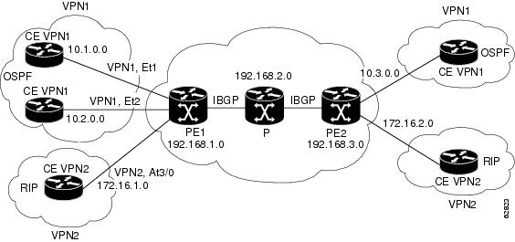
Figure 1 shows a simple MPLS VPN configuration. This configuration includes two customer MPLS VPNs, labeled VPN1 and VPN2, and a simple provider network that consists of two provider edge (PE) routers, labeled PE1 and PE2, and a provider core router labeled P. Figure 1 shows the following sample configuration:
•
•
•
•
•
•
This configuration is used in this document to explain MPLS VPN events that are monitored and managed by the PPVPN-MPLS-VPN MIB.
Figure 1 Sample MPLS VPN Configuration
Scalar Objects
Table 1 shows the supported PPVPN-MPLS-VPN MIB scalar objects.
MIB Tables
The PPVPN-MPLS-VPN MIB implementation supports the following tables described in this section:
mplsVpnVrfTableEntries in the VRF configuration table (mplsVpnVrfTable) represent the VRFs that are defined on the router. This includes recently deleted VRFs. The information in this table is also displayed with the show ip vrf command.
Each VRF is referenced by its VRF name (mplsVpnVrfName).
Table 2 lists the MIB objects and their functions for this table.
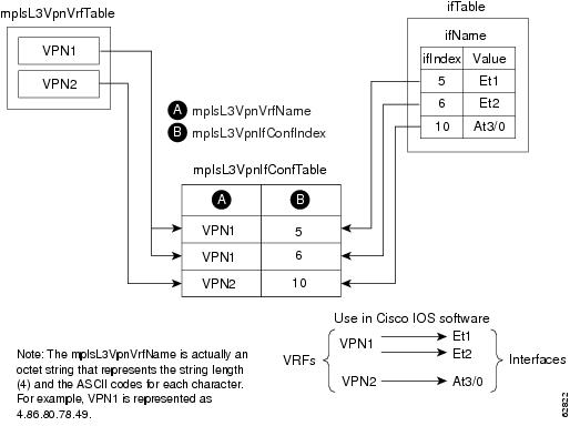
mplsVpnInterfaceConfTable
In Cisco IOS software, a VRF is associated with one MPLS VPN. Zero or more interfaces can be associated with a VRF. A VRF uses an interface that is defined in the ifTable of the Interfaces Group of MIB II (IFMIB). The IFMIB defines objects for managing interfaces. The ifTable of this MIB contains information on each interface in the network. The mplsVpnInterfaceConfTable associates a VRF from the mplsVpnVrfTable with a forwarding interface from the ifTable. Figure 2 shows the relationship between VRFs and interfaces defined in the ifTable and the mplsVpnInterfaceConfTable.
Figure 2 VRFs, the Interfaces MIB, and the mplsVpnInterfaceConfTable
Entries in the VPN interface configuration table (mplsVpnInterfaceConfTable) represent the interfaces that are assigned to each VRF. The information available in this table is also displayed with the show ip vrf command.
The mplsVpnInterfaceConfTable shows how interfaces are assigned to VRFs. A label switch router (LSR) creates an entry in this table for every interface capable of supporting MPLS VPNs.
The mplsVpnInterfaceConfTable is indexed by the following:
•
•
Table 3 lists the MIB objects and their functions for this table.
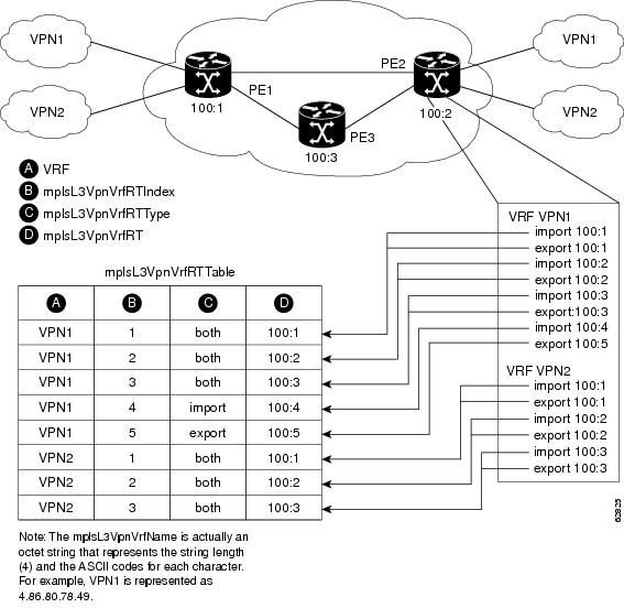
mplsVpnVrfRouteTargetTable
The route target table (mplsVpnVrfRouteTargetTable) describes the route target communities that are defined for a particular VRF. An LSR creates an entry in this table for each target configured for a VRF supporting an MPLS VPN instance.
The distribution of VPN routing information is controlled through the use of VPN route target communities, implemented by BGP extended communities. Distribution of VPN routing information works as follows:
•
•
Figure 3 shows a sample configuration and its relationship to an mplsVpnVrfRouteTargetTable. A route target table exists on each PE router. Routers with route distinguishers (RDs) 100:1, 100:2, and 100:3 are shown in the sample configuration. Routers with RDs 100:4 and 100:5 are not shown in Figure 3, but are included in the route targets for PE2 and in the mplsVpnVrfRouteTargetTable.
Figure 3 Sample Configuration and the mplsVpnVrfRouteTargetTable
The mplsVpnVrfRouteTargetTable shows the import and export route targets for each VRF. The table is indexed by the following:
•
•
•
Table 4 lists the MIB objects and their functions for this table.
mplsVpnVrfBgpNbrAddrTable
The BGP neighbor address table (mplsVpnVrfBgpNbrAddrTable) represents the MPLS external Border Gateway Protocol (eBGP) neighbors that are defined for a particular VRF. An LSR creates an entry for every BGP neighbor that is defined in the VRF's address-family.
The mplsVpnVrfBgpNbrAddrTable is indexed by the following:
•
•
•
Table 5 lists the MIB objects and their functions for this table.
mplsVpnVrfSecTable
The VRF security table (mplsVpnVrfSecTable) provides information about security for each VRF. An LSR creates an entry in this table for every VRF capable of supporting MPLS VPN.
The mplsVpnVrfSecTable augments the mplsVpnVrfTable and has the same indexing.
Table 6 lists the MIB objects and their functions for this table.
mplsVpnVrfPerfTable
The VRF performance table (mplsVpnVrfPerfTable) provides statistical performance information for each VRF. An LSR creates an entry in this table for every VRF capable of supporting MPLS VPN.
The mplsVpnVrfPerfTable augments the mplsVpnVrfTable and has the same indexing.
Table 7 lists the MIB objects and their functions for this table.
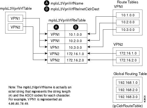
mplsVpnVrfRouteTable
The VRF routing table (mplsVpnVrfRouteTable) provides the IP routing table information for each VRF. The information available in this table can also be accessed with the show ip route vrf vrf-name command. For example, for PE1 in Figure 1:
•
Router# show ip route vrf vpn1Codes: C - connected, S - static, I - IGRP, R - RIP, M - mobile, B - BGPD - EIGRP, EX - EIGRP external, O - OSPF, IA - OSPF inter areaN1 - OSPF NSSA external type 1, N2 - OSPF NSSA external type 2E1 - OSPF external type 1, E2 - OSPF external type 2, E - EGPi - IS-IS, L1 - IS-IS level-1, L2 - IS-IS level-2, ia - IS-IS inter area* - candidate default, U - per-user static route, o - ODR P - periodic downloaded static route !Gateway of last resort is not set!10.0.0.0/32 is subnetted, 3 subnetsB 10.3.0.0 [200/0] via 192.168.2.1, 04:36:33C 10.1.0.0/16 is directly connected, Ethernet1C 10.2.0.0/16 [200/0] directly connected Ethernet2, 04:36:33•
Router# show ip route vrf vpn2Codes: C - connected, S - static, I - IGRP, R - RIP, M - mobile, B - BGPD - EIGRP, EX - EIGRP external, O - OSPF, IA - OSPF inter areaN1 - OSPF NSSA external type 1, N2 - OSPF NSSA external type 2E1 - OSPF external type 1, E2 - OSPF external type 2, E - EGPi - IS-IS, L1 - IS-IS level-1, L2 - IS-IS level-2, ia - IS-IS inter area* - candidate default, U - per-user static route, o - ODR P - periodic downloaded static route !Gateway of last resort is not set!172.16.0.0/32 is subnetted, 2 subnetsB 172.16.2.0 [200/0] via 192.168.2.1, 04:36:33C 172.16.1.0 is directly connected, ATM 3/0Figure 4 shows the relationship of the routing tables, the VRFs, and the mplsVpnVrfRouteTable. You can display information about the VPN1 and VPN2 route tables using the show ip route vrf vrf-name command. The global route table is the same as ipCidrRouteTable in the IP-FORWARD-MIB. You can display information about the global route table with the show ip route command.
Figure 4 Route Table, VRFs, and the mplsVpnVrfRouteTable
An LSR creates an entry in this table for every route that is configured, either dynamically or statically, within the context of a specific VRF capable of supporting MPLS VPN.
The mplsVpnVrfRouteTable is indexed by the following:
•
•
•
•
•
Note
Table 8 lists the MIB objects and their functions for the mplsVpnVrfRouteTable. This table represents VRF-specific routes. The global routing table is the ipCidrRouteTable in the IP-FORWARD-MIB.
Notifications
This section provides the following information about supported PPVPN-MPLS-VPN MIB notifications:
•
•
PPVPN-MPLS-VPN MIB Notification Events
The following notifications of the PPVPN-MPLS-VPN MIB are supported:
•
•
•
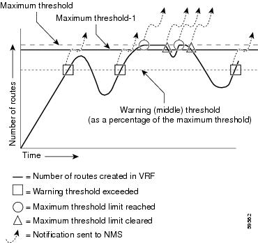
Router(config)# ip vrf vrf-nameRouter(config-vrf)# maximum routes limit warn-threshold (% of max)The warn-threshold argument is a percentage of the maximum routes specified by the limit argument. You can also configure a middle threshold with the following command, in which the limit argument represents the warning threshold:
Router(config-vrf)# maximum routes limit warn-onlyThis notification is sent to the NMS only at the time the threshold is exceeded. (See Figure 5 for a comparison of the warning and maximum thresholds.) Whenever the number of routes falls below this threshold and exceeds the threshold again, a notification is sent to the NMS.
•
Router(config)# ip vrf vrf-nameRouter(config-vrf)# maximum routes limit warn-threshold (% of max)A trap notification is sent to the NMS when you attempt to exceed the maximum threshold. Another MplsNumVrfRouteMaxThreshExceeded notification is not sent until the number of routes falls below the maximum threshold and reaches the maximum threshold again. (See Figure 5 for an example of how this notification works and for a comparison of the maximum and warning thresholds.)
Note
Prior to implementation of the PPVPN-MPLS-VPN MIB, you were not notified when this threshold (or the warning threshold) was reached.•
CISCO-IETF-PPVPN-MPLS-VPN MIB Notification Events
The following notification of the CISCO-IETF-PPVPN-MPLS-VPN MIB is supported in Cisco IOS 12.0S releases beginning with Release 12.0(30)S, and in Cisco IOS 12.2S releases beginning with Release 12.2(28)S:
•
Figure 5 Comparison of Warning and Maximum Thresholds
For information on the Cisco IOS CLI commands for configuring PPVPN-MPLS-VPN MIB notifications that are to be sent to an NMS, see the "How to Configure MPLS VPN—MIB Support" section and the "Command Reference" section.
Notification Specification
In an SNMPv1 notification, each VPN notification has a generic type identifier and an enterprise-specific type identifier for identifying the notification type.
•
•
–
–
–
–
–
–
In SNMPv2, the notification type is identified by an SnmpTrapOID varbind (variable binding consisting of an object identifier [OID] type and value) included within the notification message.
Each notification also contains two additional objects from the PPVPN-MPLS-VPN MIB. These objects provide additional information about the event, as follows:
•
•
•
Monitoring the PPVPN-MPLS-VPN MIB Notifications
When PPVPN-MPLS-VPN MIB notifications are enabled (see the snmp-server enable traps mpls vpn command), notification messages relating to specific MPLS VPN events within Cisco IOS software are generated and sent to a specified NMS in the network. Any utility that supports SNMPv1 or SNMPv2 notifications can receive notification messages.
To monitor PPVPN-MPLS-VPN MIB notification messages, log in to an NMS that supports a utility that displays SNMP notifications, and start the display utility.
Unsupported Objects in PPVPN-MPLS-VPN MIB
The following objects from the mplsVpnVrfBgpPathAttrTable are not supported with SNMP management for MPLS VPN features in Cisco IOS software:
•
•
•
•
•
•
•
•
•
•
•
•
•
•
How to Configure MPLS VPN—MIB Support
This section describes configuration tasks for the MPLS VPN—MIB Support feature. Each task in the list is identified as either required or optional.
•
•
•
The MPLS VPN notifications are enabled or disabled using the extended CLI commands (see the "Command Reference" section).
Configuring the SNMP Community
An SNMP community string defines the relationship between the SNMP manager and the agent. The community string acts like a password to regulate access to the agent on the router.
Perform this task to configure an SNMP community.
SUMMARY STEPS
1.
2.
3.
4.
5.
6.
7.
DETAILED STEPS
Configuring the Router to Send SNMP Traps
Perform this task to configure the router to sendm SNMP traps to a host.
The snmp-server host command specifies which hosts receive traps. The snmp-server enable traps command globally enables the trap production mechanism for the specified traps.
For a host to receive a trap, an snmp-server host command must be configured for that host, and, generally, the trap must be enabled globally through the snmp-server enable traps command.
Note
SUMMARY STEPS
1.
2.
3.
4.
5.
DETAILED STEPS
Configuring Threshold Values for MPLS VPN—SNMP Notifications
Perform this task to configure the following threshold values for MPLS VPN—SNMP notifications:
•
•
See Figure 5 for an example of how this notification works and for a comparison of the maximum and warning thresholds.
Note
Prior to the implementation of the PPVPN-MPLS-VPN MIB, you were not notified when this threshold (or the warning threshold) was reached.
SUMMARY STEPS
1.
2.
3.
4.
5.
DETAILED STEPS
Configuration Examples for MPLS VPN—MIB Support
This section contains the following configuration examples for the MPLS VPN—MIB Support feature:
•
•
•
Configuring the SNMP Community: Examples
The following example shows enabling a simple SNMP community group. This configuration permits any SNMP client to access all PPVPN-MPLS-VPN MIB objects with read-only access using the community string comaccess.
Router# configure terminalRouter(config)# snmp-server community comaccess roVerify that the SNMP master agent is enabled for the MPLS VPN—MIB Support feature:
Router# show running-config | include snmp-server
Building configuration....snmp-server community comaccess RO
Note
Configuring the Router to Send SNMP Traps: Example
The following example shows you how to enable the router to send MPLS VPN notifications to host 172.20.2.160 using the comaccess community string if a VRF transitions from an up or down state:
Router# configure terminalRouter(config)# snmp-server host 172.20.2.160 traps comaccess mpls-vpnRouter(config)# snmp-server enable traps mpls vpn vrf-down vrf-upConfiguring Threshold Values for MPLS VPN—SNMP Notifications: Examples
The following example shows how to set a maximum threshold of 10,000 routes and a warning threshold that is 80 percent of the maximum threshold for a VRF named vpn1 on a router:
Router(config)# ip vrf vpn1Router(config-vrf)# maximum routes 10000 80The following example shows how to set a warning threshold of 10,000 routes for a VRF named vpn2 on a router. An error message is generated; however, additional routes are still allowed because a maximum route threshold is not set with this command.
Router(config)# ip vrf vpn2Router(config-vrf)# maximum routes 10000 warn-only
Additional References
The following sections provide additional references related to the MPLS VPN-MIB Support feature.
Related Documents
MPLS VPN configuration tasks
Basic MPLS VPN carrier supporting carrier configuration tasks
Standards
draft-ietf-ppvpn-mpls-vpn-mib-05
MPLS/BGP Virtual Private Network Management Information Base Using SMIv2
MIBs
•
•
To locate and download MIBs for selected platforms, Cisco IOS releases, and feature sets, use Cisco MIB Locator found at the following URL:
RFCs
Technical Assistance
Command Reference
The following commands are introduced or modified in the feature or features documented in this module. For information about these commands, see the Cisco IOS Multiprotocol Label Switching Command Reference at http://www.cisco.com/en/US/docs/ios/mpls/command/reference/mp_book.html. For information about all Cisco IOS commands, use the Command Lookup Tool at http://tools.cisco.com/Support/CLILookup or the Cisco IOS Master Command List, All Releases, at http://www.cisco.com/en/US/docs/ios/mcl/allreleasemcl/all_book.html.
•
Feature Information for MPLS VPN—MIB Support
Table 9 lists the release history for this feature.
Not all commands may be available in your Cisco IOS software release. For release information about a specific command, see the command reference documentation.
Use Cisco Feature Navigator to find information about platform support and software image support. Cisco Feature Navigator enables you to determine which Cisco IOS and Catalyst OS software images support a specific software release, feature set, or platform. To access Cisco Feature Navigator, go to http://www.cisco.com/go/cfn. An account on Cisco.com is not required.
Note
Table 9 Feature Information for MPLS VPN—MIB Support
MPLS VPN—MIB Support
12.0(21)ST
12.0(22)S
12.2(13)S
12.2(15)T
12.0(24)S1
12.0(25)S
12.0(30)S
12.2(28)SB
12.2(33)SRA
12.2(31)SB2
12.2(33)SXH
12.4(20)TThis feature was introduced into Cisco IOS Release 12.0(21)ST.
This feature was integrated into Cisco IOS Release 12.0(22)S.
This feature was integrated into Cisco IOS Release 12.2(13)S.
The PPVPN-MPLS-VPN MIB notifications were supported in Cisco IOS Release 12.2(13)T. The PPVPN-MPLS-VPN MIB tables were integrated into Cisco IOS Release 12.2(15)T.
The feature was implemented for ATM and Frame Relay subinterfaces and integrated into Cisco IOS Release 12.0(24)S1.
This feature was integrated into Cisco IOS Release 12.0(25)S.
This feature was updated with the MPLS VPN Trap Enhancement feature, which introduced the cMplsNumVrfRouteMaxThreshCleared notification. (See "CISCO-IETF-PPVPN-MPLS-VPN MIB Notification Events" for more information.) The max-thresh-cleared keyword was added to the snmp-server enable traps mpls vpn command.
This feature was integrated into Cisco IOS Release 12.2(28)SB.
This feature was integrated into Cisco IOS Release 12.2(33)SRA.
This feature was implemented into Cisco IOS Release 12.2(31)SB2.
This feature was implemented into Cisco IOS Release 12.2(33)SXH.
This feature was integrated into Cisco IOS Release 12.4(20)T.
Glossary
autonomous system—A collection of networks that share the same routing protocol and that are under the same system administration.
ASN.1—Abstract Syntax Notation One. The data types independent of particular computer structures and representation techniques. Described by ISO International Standard 8824.
BGP—Border Gateway Protocol. The exterior Border Gateway Protocol used to exchange routing information between routers in separate autonomous systems. BGP uses TCP. Because TCP is a reliable protocol, BGP does not experience problems with dropped or fragmented data packets.
BGP prefixes—A route announcement using the BGP. A prefix is composed of a path of autonomous system numbers, indicating which networks the packet must pass through, and the IP block that is being routed. A BGP prefix would look something like: 701 1239 42 206.24.14.0/24. (The /24 part is referred to as a CIDR mask.) The /24 indicates that there are 24 ones in the netmask for this block starting from the left side. A /24 corresponds to the natural mask 255.255.255.0.
Cisco Express Forwarding—An advanced Layer 3 IP switching technology. Cisco Express Forwarding optimizes network performance and scalability for networks with large and dynamic traffic patterns.
CE router—customer edge router. A router on the border between a VPN provider and a VPN customer that belongs to the customer.
CIDR—classless interdomain routing. A technique supported by BGP4 and based on route aggregation. CIDR allows routers to group routes to reduce the quantity of routing information carried by the core routers. With CIDR, several IP networks appear to networks outside the group as a single, larger entity. With CIDR, IP addresses and their subnet masks are written as four octets, separated by periods, followed by a forward slash and a two-digit number that represents the subnet mask.
community—In SNMP, a logical group of managed devices and NMSs in the same administrative domain.
community name—See community string.
community string—A text string that acts as a password and is used to authenticate messages sent between a managed station and a router containing an SNMP agent. The community string is sent in every packet between the manager and the client. Also called a community name.
IETF—Internet Engineering Task Force. A task force consisting of over 80 working groups responsible for developing Internet standards. The IETF operates under the auspices of ISOC. See also ISOC.
informs—A type of notification message that is more reliable than a conventional trap notification message, because the informs message notification requires acknowledgment, and a trap notification does not.
ISOC—Internet Society. An international nonprofit organization, founded in 1992, that coordinates the evolution and use of the Internet. In addition, ISOC delegates authority to other groups related to the Internet, such as the IAB. ISOC is headquartered in Reston, Virginia (United States).
label—A short, fixed-length data construct that tells switching nodes how to forward data (packets or cells).
LDP—Label Distribution Protocol. A standard protocol between MPLS-enabled routers that is used for the negotiation of the labels (addresses) used to forward packets.
LFIB—Label Forwarding Information Base. In the Cisco Label Switching system, the data structure for storing information about incoming and outgoing tags (labels) and associated equivalent packets suitable for labeling.
LSR—label switch router. A device that forwards MPLS packets based on the value of a fixed-length label encapsulated in each packet.
MIB—Management Information Base. A database of network management information that is used and maintained by a network management protocol such as SNMP or CMIP. The value of a MIB object can be changed or retrieved using SNMP or CMIP commands, usually through a GUI network management system. MIB objects are organized in a tree structure that includes public (standard) and private (proprietary) branches.
MPLS—Multiprotocol Label Switching. A method for forwarding packets (frames) through a network. It enables routers at the edge of a network to apply labels to packets (frames). ATM switches or existing routers in the network core can switch packets according to the labels with minimal lookup overhead.
MPLS interface—An interface on which MPLS traffic is enabled.
MPLS VPN—Multiprotocol Label Switching Virtual Private Network. An IP network infrastructure delivering private network services over a public infrastructure using a Layer 3 backbone. Using MPLS VPNs in a Cisco IOS network provides the capability to deploy and administer scalable Layer 3 VPN backbone services including applications, data hosting network commerce, and telephony services to business customers.
For an MPLS VPN solution, an MPLS VPN is a set of provider edge routers that are connected by means of a common "backbone" network to supply private IP interconnectivity between two or more customer sites for a given customer. Each VPN has a set of provisioning templates and policies and can span multiple provider administrative domains (PADs).
NMS—network management system. A powerful, well-equipped computer (typically an engineering workstation) that is used by a network administrator to communicate with other devices in the network. An NMS is typically used to manage network resources, gather statistics, and perform a variety of network administration and configuration tasks.
notification—A message sent by an SNMP agent to a network management station, console, or terminal to indicate that a significant event within Cisco IOS software has occurred. See also trap.
PE router—provider edge router. A router on the border between a VPN provider and a VPN customer that belongs to the provider.
PPVPN—Provider-Provisioned VPN. The name of the IETF working group that is developing the PPVPN-MPLS-VPN MIB.
QoS—quality of service. A measure of performance for a transmission system that reflects its transmission quality and service availability.
RSVP—Resource Reservation Protocol. A protocol for reserving network resources to provide quality of service guarantees to application flows.
RT—route target. An extended community attribute that identifies a group of routers and, in each router of that group, a subset of forwarding tables maintained by the router that can be populated with a BGP route carrying that extended community attribute. The RT is a 64-bit value by which Cisco IOS discriminates routes for route updates in VRFs.
SNMP—Simple Network Management Protocol. The network management protocol used almost exclusively in TCP/IP networks. SNMP provides a means to monitor and control network devices, and to manage configurations, statistics collection, performance, and security. See also SNMP2.
SNMP2—SNMP Version 2. Version 2 of the popular network management protocol. SNMP2 supports centralized and distributed network management strategies, and includes improvements in the Structure of Management Information (SMI), protocol operations, management architecture, and security. See also SNMP.
traffic engineering—The techniques and processes used to cause routed traffic to travel through the network on a path other than the one that would have been chosen if standard routing methods had been used.
trap—A message sent by an SNMP agent to a network management station, console, or terminal, indicating that a significant event occurred. Traps (notifications) are less reliable than inform requests, because the receiver does not send an acknowledgment when it receives a trap. The sender cannot determine if the trap was received. See also notification.
VPN—Virtual Private Network. A group of sites that, as the result of a set of administrative policies, are able to communicate with each other over a shared backbone network. A VPN is a secure IP-based network that shares resources on one or more physical networks. A VPN contains geographically dispersed sites that can communicate securely over a shared backbone. See also MPLS VPN.
VPN ID—A mechanism that identifies a VPN based on RFC 2685. A VPN ID consists of an Organizational Unique Identifier (OUI), a three-octet hex number assigned by the IEEE Registration Authority, and a VPN index, a four-octet hex number, which identifies the VPN within the company.
VRF—VPN routing and forwarding instance. A VRF consists of an IP routing table, a derived forwarding table, a set of interfaces that use the forwarding table, and a set of rules and routing protocols that determine what goes into the forwarding table. In general, a VRF includes the routing information that defines a customer VPN site that is attached to a PE router.
Cisco and the Cisco Logo are trademarks of Cisco Systems, Inc. and/or its affiliates in the U.S. and other countries. A listing of Cisco's trademarks can be found at www.cisco.com/go/trademarks. Third party trademarks mentioned are the property of their respective owners. The use of the word partner does not imply a partnership relationship between Cisco and any other company. (1005R)
Any Internet Protocol (IP) addresses used in this document are not intended to be actual addresses. Any examples, command display output, and figures included in the document are shown for illustrative purposes only. Any use of actual IP addresses in illustrative content is unintentional and coincidental.
© 2002,2006 - 2008 Cisco Systems, Inc. All rights reserved.