Feedback
Table Of Contents
Step 1—Configuring the Host Name, Password, and Time Stamps
Step 2—Configuring Local AAA Security
Step 3—Configuring the Fast Ethernet 100BaseT Interface
Step 4—Commissioning the T1 Controllers
Step 5—Configuring the Serial Channels to Let Modem Calls Come in
Step 6—Configuring the Modems and Lines
Step 7—Testing Async Shell Connections
Step 8—Setting Up IP Address Pools
Step 9—Configuring the Group-Async Interface
Step 10—Testing Async PPP Connections
Step 12—Configuring Definitions for Remote LAN Sites
Step 13—Configuring a Backhaul Routing Protocol
Step 14—Confirming the Final Running Configuration
Step 15—Saving the Configuration
Step 16—Testing Sync PPP Connections to Remote LANs
Step 17—Adding More Remote LAN Sites as Needed
Cisco AS5300 Configuration
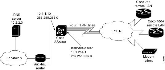
This chapter describes how to configure the Cisco AS5300 to receive calls from the Cisco 1604, Cisco 766, and remote modem users.
Site Profile Characteristics
shows the network topology from the Cisco AS5300's perspective.
Figure 2-1
Network Topology
Note
Before you perform the configuration tasks in this chapter, be sure you understand the overall dial case action plan described in the previous chapter "."
provides detailed information about each end of the connection. This is the network administrator's top-level design table.
Table 2-1 Site Characteristics
IP Address
IP Address
Password1Cisco AS53002
10.1.254.1 255.255.255.03
10.1.1.10 255.255.255.0
40855512344
hq-sanjose
hq-sanjose-pw
Cisco 766
10.1.254.3 255.255.255.0
10.1.3.1 255.255.255.0
Directory number = 5305558084
soho-tahoe
tahoe-pw
Cisco 1604
10.1.254.4 255.255.255.0
10.1.4.1 255.255.255.0
robo-austin
austin-pw
1 Make sure to use your own host names and passwords. For example soho-tahoe and tahoe-pw are for this case study's purpose only.
2 The subnet 10.1.2.0 255.255.255.0 is used for the loopback interface and the local IP address pools.
3 This address is configured on the Cisco AS5300's dialer interface.
4 This is the PRI telephone number assigned to the central site (hq-sanjose). This number is often called the hunt group number, which distributes calls among the available B channels. All four PRI trunks on the Cisco AS5300 should be assigned to this number by the PRI provider.
Cisco IOS Release 12.0 is running inside the access server. If the startup configuration is blank, the following screen is displayed at bootup. The automatic setup script is engaged. Enter no when you are asked the question, "Would you like to enter the initial configuration dialog? [yes]: no."
In this case study, the Cisco AS5300 is manually configured using the Cisco IOS software. The automatic setup script is not used.
Note
Copyright (c) 1994-1995 by cisco Systems, Inc.AS5300 processor with 32768 Kbytes of main memoryprogram load complete, entry point: 0x80008000, size: 0xf4b10Self decompressing the image : ################################################################################################################################################################################################################################################################################################################################################################################################### [OK]Restricted Rights LegendUse, duplication, or disclosure by the Government issubject to restrictions as set forth in subparagraph(c) of the Commercial Computer Software - RestrictedRights clause at FAR sec. 52.227-19 and subparagraph(c) (1) (ii) of the Rights in Technical Data and ComputerSoftware clause at DFARS sec. 252.227-7013.cisco Systems, Inc.170 West Tasman DriveSan Jose, California 95134-1706Cisco Internetwork Operating System SoftwareIOS (tm) 5300 Software (C5300-JS-M), Version 12.0(x)Copyright (c) 1986-1998 by cisco Systems, Inc.Compiled Tue 07-Jul-98 15:26 by xxxxImage text-base: 0x600088E8, data-base: 0x608F4000cisco AS5300 (R4K) processor (revision A.04) with 32768K/8192K bytes of memory.Processor board ID 04614948R4700 processor, Implementation 33, Revision 1.0 (512KB Level 2 Cache)Bridging software.X.25 software, Version 3.0.0.SuperLAT software copyright 1990 by Meridian Technology Corp).TN3270 Emulation software.Primary Rate ISDN software, Version 1.1.Backplane revision 1Manufacture Cookie is not programmed.1 Ethernet/IEEE 802.3 interface(s)1 FastEthernet/IEEE 802.3 interface(s)96 terminal line(s)4 Channelized T1/PRI port(s)128K bytes of non-volatile configuration memory.16384K bytes of processor board System flash (Read/Write)4096K bytes of processor board Boot flash (Read/Write)Cisco Internetwork Operating System SoftwareIOS (tm) 5300 Software (C5300-JS-M), Version 12.0(x),Copyright (c) 1986-1998 by cisco Systems, Inc.Compiled Tue 07-Jul-98 15:26 by xxx00:00:50: %MICA-5-BOARDWARE_RUNNING: Slot 2 is running boardware version 2.5.0.8--- System Configuration Dialog ---At any point you may enter a question mark '?' for help.Use ctrl-c to abort configuration dialog at any prompt.Default settings are in square brackets '[]'.Would you like to enter the initial configuration dialog? [yes]: noPress RETURN to get started!Router>
Note
Overview of Tasks
Perform the following steps to configure the access server:
•
•
•
•
•
•
•
•
•
•
•
•
•
•
•
•
•
•
•
•
Step 1—Configuring the Host Name, Password, and Time Stamps
Assign a host name to the Cisco AS5300, enable basic security, and turn on time stamping. Configuring a host name allows you to distinguish between different network devices. Enable passwords allow you to prevent unauthorized configuration changes. Time stamps help you trace debug output for testing connections. Not knowing exactly when an event occurs hinders you from examining background processes.
Configure
To configure the host name, enable password, and time stamps use the following commands beginning in user EXEC mode:
1
Enter privileged EXEC mode.
2
Enter global configuration mode1 .
3
Assign a host name to the access server2 .
This host name is typically used during authentication with PPP peers.
4
Enter a secret enable password, which secures privileged EXEC mode3 .
5
Encrypt passwords in the configuration file for greater security4 .
6
hq-sanjose(config)# service timestamps log datetime msecEnable millisecond time stamping on debug and logging output. Time stamps are useful for detailed access troubleshooting.
1 If the logging output generated by the access server interferes with your terminal screen, redisplay your current command line using the Tab key.
2 The step is verified by the router prompt changing from Router(config)# to hq-sanjose(config)#.
3 Make sure to change "letmein" to your own secret password.
4 Additional measures should be used, as the passwords are not strongly encrypted by today's standards.
Verify
To verify the configuration:
•
hq-sanjose# disablehq-sanjose> enablePassword: letmeinhq-sanjose# show privilegeCurrent privilege level is 15hq-sanjose#•
hq-sanjose# show runningBuilding configuration...Current configuration:!version 12.0service timestamps debug datetime msecservice timestamps log datetime msecservice password-encryption!hostname hq-sanjose!enable secret 5 $1$.voA$9/8.Zoil3jeWJMP6hEE6U0!----- snip ----Tips
If you have trouble:
•
•
•
hq-sanjose# show tech-support ?ipmulticast IP multicast related informationpage Page through outputpassword Include passwordsrsvp IP RSVP related information<cr>Step 2—Configuring Local AAA Security
The Cisco IOS security model to use on all Cisco devices is authentication, authorization, and accounting (AAA). AAA provides the primary framework through which you set up access control on the access server.
•
•
•
In this case study, the same authentication method is used on all interfaces. AAA is set up to use the local database configured on the router. This local database is created with the username configuration commands.
Note
Configure
To configure local AAA security, use the following commands beginning in global configuration mode:
1
hq-sanjose(config)# username joe-admin password joe-password
Create a local login database and username for yourself1 .
This step also prevents you from getting locked out of the access server.
2
hq-sanjose(config)# aaa new-model
Initiate the AAA access control system.
This step immediately locks down login and PPP authentication.
3
hq-sanjose(config)# aaa authentication login default local
Configure AAA to perform login authentication using the local username database.
The login keyword authenticates shell/EXEC users.
4
hq-sanjose(config)# aaa authentication ppp default if-needed local
Configure PPP authentication to use the local database if the session was not already authenticated by login.
1 Make sure to change "joe-admin" to your own username and "joe-password" to your own password.
Verify
To verify the configuration:
•
hq-sanjose# loginUser Access VerificationUsername: joe-adminPassword: joe-passwordhq-sanjose#•
hq-sanjose# show runningBuilding configuration...Current configuration:!version 12.0service timestamps debug datetime msecservice timestamps log datetime msecservice password-encryption!hostname hq-sanjose!aaa new-modelaaa authentication login default localaaa authentication ppp default if-needed localenable secret 5 $1$.voA$9/8.Zoil3jeWJMP6hEE6U0!username joe-admin password 7 <removed>!----- snip ----Step 3—Configuring the Fast Ethernet 100BaseT Interface
Assign an IP address, line speed, and duplex mode to the Fast Ethernet interface. The Fast Ethernet interface supports 10- and 100-Mbps speeds.
The default priority search order for auto negotiating the line speed is as follows:
1
2
3
4
Configure
To configure the Fast ethernet 100BaseT interface, use the following commands beginning in global configuration mode:
1
hq-sanjose(config-if)# ip address 10.1.1.10 255.255.255.0Configure the IP address and subnet mask on the Fast Ethernet interface.
2
Auto negotiate the line speed based on the peer routers, hubs, and switch media.
3
Auto negotiate duplex mode.
4
%LINK-3-UPDOWN: Interface FastEthernet0, changed state to upBring up the interface1 .
1 This command changes the state of the interface from administratively down to up.
Verify
To verify the configuration:
•
hq-sanjose# show ip interface brief fastethernet 0Interface IP-Address OK? Method Status ProtocolFastEthernet0 10.1.1.10 YES manual up up•
hq-sanjose# ping 10.1.1.1Type escape sequence to abort.Sending 5, 100-byte ICMP Echos to 10.1.1.1, timeout is 2 seconds:!!!!!Success rate is 100 percent (5/5), round-trip min/avg/max = 4/5/8 ms•
hq-sanjose# show interface fastethernet 0FastEthernet0 is up, line protocol is upHardware is DEC21140AE, address is 00e0.1e6b.2ffb (bia 00e0.1e6b.2ffb)Internet address is 10.1.1.10 /24MTU 1500 bytes, BW 100000 Kbit, DLY 100 usec, rely 255/255, load 1/255Encapsulation ARPA, loopback not set, keepalive set (10 sec), auto duplex,100BaseTX/FX, auto speedARP type: ARPA, ARP Timeout 04:00:00Last input 00:00:05, output 00:00:05, output hang neverLast clearing of "show interface" counters neverQueueing strategy: fifoOutput queue 0/40, 0 drops; input queue 0/120, 0 drops5 minute input rate 0 bits/sec, 0 packets/sec5 minute output rate 0 bits/sec, 0 packets/sec282 packets input, 68476 bytes, 0 no bufferReceived 282 broadcasts, 0 runts, 0 giants, 0 throttles0 input errors, 0 CRC, 0 frame, 0 overrun, 0 ignored, 0 abort0 watchdog, 0 multicast0 input packets with dribble condition detected176 packets output, 16936 bytes, 0 underruns0 output errors, 0 collisions, 0 interface resets0 babbles, 0 late collision, 0 deferred0 lost carrier, 0 no carrier0 output buffer failures, 0 output buffers swapped out•
hq-sanjose# show runningBuilding configuration...Current configuration:!----- snip ----!interface FastEthernet0ip address 10.1.1.10 255.255.255.0no ip directed-broadcastno ip route-cacheno ip mroute-cacheduplex autospeed auto!----- snip ----Tips
If you have trouble:
•
•
Step 4—Commissioning the T1 Controllers
Configure the T1 controllers to allow calls to come into the access server. You must specify the following information for each controller: framing type, line code type, clock source, and timeslot assignments.
Configure
To configure the controllers, use the following commands beginning in global configuration mode:
1
hq-sanjose(config)# isdn switch-type primary-ni
Enter your telco's switch type.
This example uses primary national ISDN 1.
2
Enter controller configuration mode for the first T1 controller, which is 0. The controller ports are labeled 0 through 3 on the quad T1/PRI card.
3
Enter the T1 framing type.
This example uses extended super frame.
4
Enter the T1 line code type.
This example uses B8ZS.
5
Configure the access server to get its primary clocking from the T1 line assigned to controller 0.
Line clocking comes from the remote switch.
6
Assign all 24 T1 timeslots as ISDN PRI channels1 .
7
Exit back to global configuration mode.
8
Configure the second controller, controller T1 1.
Set the clocking to secondary. If the line clocking from controller T1 0 fails, the access server will receive its clocking from controller T1 1.
9
Configure the remaining two controllers.
Set both clocking entries to internal. The primary and secondary clock sources have already been assigned.
1 After you enter this command, a D-channel serial interface is instantly created (for example S0:23, S1:23, and so on) in the configuration file as well as the individual B-channel serial interfaces (for example S0:0, S0:1, ...). The D-channel interface functions like a dialer for all the 23 B channels using the controller.
Verify
To verify the configuration:
•
hq-sanjose# show controller t1T1 0 is up.No alarms detected.Version info of slot 0: HW: 2, Firmware: 16, PLD Rev: 0Manufacture Cookie Info:EEPROM Type 0x0001, EEPROM Version 0x01, Board ID 0x42,Board Hardware Version 1.0, Item Number 73-2217-4,Board Revision A0, Serial Number 07557185,PLD/ISP Version 0.0, Manufacture Date 17-Dec-1997.Framing is ESF, Line Code is B8ZS, Clock Source is Line Primary.Data in current interval (25 seconds elapsed):0 Line Code Violations, 0 Path Code Violations0 Slip Secs, 0 Fr Loss Secs, 0 Line Err Secs, 0 Degraded Mins0 Errored Secs, 0 Bursty Err Secs, 0 Severely Err Secs, 0 Unavail SecsTotal Data (last 24 hours)0 Line Code Violations, 0 Path Code Violations,0 Slip Secs, 0 Fr Loss Secs, 0 Line Err Secs, 0 Degraded Mins,0 Errored Secs, 0 Bursty Err Secs, 0 Severely Err Secs, 0 Unavail SecsT1 1 is up.No alarms detected.Version info of slot 0: HW: 2, Firmware: 16, PLD Rev: 0Manufacture Cookie Info:EEPROM Type 0x0001, EEPROM Version 0x01, Board ID 0x42,Board Hardware Version 1.0, Item Number 73-2217-4,Board Revision A0, Serial Number 07557185,PLD/ISP Version 0.0, Manufacture Date 17-Dec-1997.Framing is ESF, Line Code is B8ZS, Clock Source is Line Secondary.Data in current interval (827 seconds elapsed):0 Line Code Violations, 0 Path Code Violations0 Slip Secs, 0 Fr Loss Secs, 0 Line Err Secs, 0 Degraded Mins0 Errored Secs, 0 Bursty Err Secs, 0 Severely Err Secs, 0 Unavail SecsTotal Data (last 24 hours)0 Line Code Violations, 0 Path Code Violations,0 Slip Secs, 0 Fr Loss Secs, 0 Line Err Secs, 0 Degraded Mins,0 Errored Secs, 0 Bursty Err Secs, 0 Severely Err Secs, 0 Unavail SecsT1 2 is administratively down.Transmitter is sending remote alarm.Receiver has loss of signal.Version info of slot 0: HW: 2, Firmware: 16, PLD Rev: 0Manufacture Cookie Info:EEPROM Type 0x0001, EEPROM Version 0x01, Board ID 0x42,Board Hardware Version 1.0, Item Number 73-2217-4,Board Revision A0, Serial Number 07557185,PLD/ISP Version 0.0, Manufacture Date 17-Dec-1997.Framing is ESF, Line Code is B8ZS, Clock Source is Internal.Data in current interval (868 seconds elapsed):3 Line Code Violations, 0 Path Code Violations0 Slip Secs, 868 Fr Loss Secs, 2 Line Err Secs, 0 Degraded Mins0 Errored Secs, 0 Bursty Err Secs, 0 Severely Err Secs, 868 Unavail SecsTotal Data (last 24 hours)182 Line Code Violations, 0 Path Code Violations,1 Slip Secs, 86400 Fr Loss Secs, 125 Line Err Secs, 0 Degraded Mins,0 Errored Secs, 0 Bursty Err Secs, 0 Severely Err Secs, 86400 Unavail SecsT1 3 is administratively down.Transmitter is sending remote alarm.Receiver has loss of signal.Version info of slot 0: HW: 2, Firmware: 16, PLD Rev: 0Manufacture Cookie Info:EEPROM Type 0x0001, EEPROM Version 0x01, Board ID 0x42,Board Hardware Version 1.0, Item Number 73-2217-4,Board Revision A0, Serial Number 07557185,PLD/ISP Version 0.0, Manufacture Date 17-Dec-1997.Framing is ESF, Line Code is B8ZS, Clock Source is Internal.Data in current interval (142 seconds elapsed):0 Line Code Violations, 0 Path Code Violations0 Slip Secs, 142 Fr Loss Secs, 0 Line Err Secs, 0 Degraded Mins0 Errored Secs, 0 Bursty Err Secs, 0 Severely Err Secs, 142 Unavail SecsTotal Data (last 24 hours)12 Line Code Violations, 0 Path Code Violations,0 Slip Secs, 86400 Fr Loss Secs, 8 Line Err Secs, 0 Degraded Mins,0 Errored Secs, 0 Bursty Err Secs, 0 Severely Err Secs, 86400 Unavail Secs•
In the following example, notice that the frame loss and line errors present in data intervals 1 through 4 were eventually cleared up in the current data interval.
Note
hq-sanjose# show controller t1 0T1 0 is up.No alarms detected.Version info of slot 0: HW: 2, Firmware: 16, PLD Rev: 0Manufacture Cookie Info:EEPROM Type 0x0001, EEPROM Version 0x01, Board ID 0x42,Board Hardware Version 1.0, Item Number 73-2217-4,Board Revision A0, Serial Number 07557185,PLD/ISP Version 0.0, Manufacture Date 17-Dec-1997.Framing is ESF, Line Code is B8ZS, Clock Source is Line Primary.Data in current interval (72 seconds elapsed):0 Line Code Violations, 0 Path Code Violations0 Slip Secs, 0 Fr Loss Secs, 0 Line Err Secs, 0 Degraded Mins0 Errored Secs, 0 Bursty Err Secs, 0 Severely Err Secs, 0 Unavail SecsData in Interval 1:0 Line Code Violations, 0 Path Code Violations0 Slip Secs, 405 Fr Loss Secs, 14 Line Err Secs, 0 Degraded Mins0 Errored Secs, 0 Bursty Err Secs, 0 Severely Err Secs, 405 Unavail SecsData in Interval 2:0 Line Code Violations, 0 Path Code Violations0 Slip Secs, 450 Fr Loss Secs, 1 Line Err Secs, 0 Degraded Mins0 Errored Secs, 0 Bursty Err Secs, 0 Severely Err Secs, 450 Unavail SecsData in Interval 3:0 Line Code Violations, 0 Path Code Violations0 Slip Secs, 450 Fr Loss Secs, 1 Line Err Secs, 0 Degraded Mins0 Errored Secs, 0 Bursty Err Secs, 0 Severely Err Secs, 450 Unavail SecsData in Interval 4:0 Line Code Violations, 0 Path Code Violations0 Slip Secs, 450 Fr Loss Secs, 2 Line Err Secs, 0 Degraded Mins0 Errored Secs, 0 Bursty Err Secs, 0 Severely Err Secs, 450 Unavail Secs-------------------------------- snip ------------------------------------------•
hq-sanjose# show runningBuilding configuration...Current configuration:!----- snip ----!isdn switch-type primary-ni!controller T1 0framing esfclock source line primarylinecode b8zspri-group timeslots 1-24!controller T1 1framing esfclock source line secondarylinecode b8zspri-group timeslots 1-24!controller T1 2framing esfclock source internallinecode b8zspri-group timeslots 1-24!controller T1 3framing esfclock source internallinecode b8zspri-group timeslots 1-24!----- snip ----Tips
If you have trouble:
•
•
Step 5—Configuring the Serial Channels to Let Modem Calls Come in
The async shell service is the first service to enable. Configure the D channels to allow incoming voice calls to be routed to the integrated modems.
In the section "Configuration DDR," the D channel configuration is expanded to also accept ISDN synchronous PPP calls from the remote offices. Cisco recommends getting modem users up first.
Configure
To configure the serial channels, use the following commands beginning in global configuration mode:
1
Enter configuration mode for the D-channel serial interface that corresponds to controller T1 01 .
The behavior of S0:0 through S0:22 is controlled by the configuration instructions provided for S0:23. This concept is also true for the other remaining D channel configurations.
2
hq-sanjose(config-if)# no shutdownEnable analog modem voice calls coming in over the B channels to be connected to the integrated modems.
3
hq-sanjose(config-if)# exit
Exit back to global configuration mode.
4
hq-sanjose(config)# interface serial 1:23
hq-sanjose(config-if)# isdn incoming-voice modem

hq-sanjose(config-if)# no shutdown
hq-sanjose(config-if)# exit
hq-sanjose(config)# interface serial 2:23
hq-sanjose(config-if)# isdn incoming-voice modem
hq-sanjose(config-if)# no shutdown
hq-sanjose(config-if)# exit
hq-sanjose(config)# interface serial 3:23
hq-sanjose(config-if)# isdn incoming-voice modem
hq-sanjose(config-if)# no shutdown
hq-sanjose(config-if)# exit
hq-sanjose(config)#Configure the three remaining D channels with the same settings.
1 The D channel is the signaling channel.
Verify
To verify the configuration:
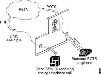
•
Figure 2-2
Voice Test Call
•
hq-sanjose# show interface serial 0:23Serial0:23 is up, line protocol is up (spoofing)Hardware is DSX1MTU 1500 bytes, BW 64 Kbit, DLY 20000 usec, rely 255/255, load 1/255Encapsulation PPP, loopback not setDTR is pulsed for 1 seconds on resetLast input 00:00:12, output 00:00:12, output hang neverLast clearing of "show interface" counters neverInput queue: 0/75/0 (size/max/drops); Total output drops: 0Queueing strategy: weighted fairOutput queue: 0/1000/64/0 (size/max total/threshold/drops)Conversations 0/1/256 (active/max active/max total)Reserved Conversations 0/0 (allocated/max allocated)5 minute input rate 0 bits/sec, 0 packets/sec5 minute output rate 0 bits/sec, 0 packets/sec937 packets input, 19612 bytes, 0 no bufferReceived 0 broadcasts, 0 runts, 2 giants, 0 throttles2 input errors, 0 CRC, 0 frame, 0 overrun, 0 ignored, 0 abort945 packets output, 4263 bytes, 0 underruns0 output errors, 0 collisions, 4 interface resets0 output buffer failures, 0 output buffers swapped out3 carrier transitionsTimeslot(s) Used:24, Transmitter delay is 0 flags
Note
•
hq-sanjose# show isdn statusThe current ISDN Switchtype = primary-niISDN Serial0:23 interfaceLayer 1 Status:ACTIVELayer 2 Status:TEI = 0, State = MULTIPLE_FRAME_ESTABLISHEDLayer 3 Status:No Active Layer 3 Call(s)Activated dsl 0 CCBs = 0Total Allocated ISDN CCBs = 0ISDN Serial1:23 interfaceLayer 1 Status:ACTIVELayer 2 Status:TEI = 0, State = MULTIPLE_FRAME_ESTABLISHEDLayer 3 Status:No Active Layer 3 Call(s)Activated dsl 1 CCBs = 0Total Allocated ISDN CCBs = 0ISDN Serial2:23 interfaceLayer 1 Status:ACTIVELayer 2 Status:TEI = 0, State = MULTIPLE_FRAME_ESTABLISHEDLayer 3 Status:No Active Layer 3 Call(s)Activated dsl 2 CCBs = 0Total Allocated ISDN CCBs = 0ISDN Serial3:23 interfaceLayer 1 Status:ACTIVELayer 2 Status:TEI = 0, State = MULTIPLE_FRAME_ESTABLISHEDLayer 3 Status:No Active Layer 3 Call(s)Activated dsl 3 CCBs = 0Total Allocated ISDN CCBs = 0Note the following information:
•
•
•
•
hq-sanjose# show isdn servicePRI Channel Statistics:ISDN Se0:23, Channel (1-31)Activated dsl 0State (0=Idle 1=Propose 2=Busy 3=Reserved 4=Restart 5=Maint)0 0 2 0 0 0 0 0 0 0 0 0 0 0 0 0 0 0 0 0 0 0 0 3 3 3 3 3 3 3 3Channel (1-31) Service (0=Inservice 1=Maint 2=Outofservice)0 0 0 0 0 0 0 0 0 0 0 0 0 0 0 0 0 0 0 0 0 0 0 2 2 2 2 2 2 2 2ISDN Se1:23, Channel (1-31)Activated dsl 0State (0=Idle 1=Propose 2=Busy 3=Reserved 4=Restart 5=Maint)0 0 0 0 0 0 0 0 0 0 0 0 0 0 0 0 0 0 0 0 0 0 0 3 3 3 3 3 3 3 3Channel (1-31) Service (0=Inservice 1=Maint 2=Outofservice)0 0 0 0 0 0 0 0 0 0 0 0 0 0 0 0 0 0 0 0 0 0 0 2 2 2 2 2 2 2 2ISDN Se2:23, Channel (1-31)Activated dsl 0State (0=Idle 1=Propose 2=Busy 3=Reserved 4=Restart 5=Maint)0 0 0 0 0 0 0 0 0 0 0 0 0 0 0 0 0 0 0 0 0 0 0 3 3 3 3 3 3 3 3Channel (1-31) Service (0=Inservice 1=Maint 2=Outofservice)0 0 0 0 0 0 0 0 0 0 0 0 0 0 0 0 0 0 0 0 0 0 0 2 2 2 2 2 2 2 2ISDN Se3:23, Channel (1-31)Activated dsl 0State (0=Idle 1=Propose 2=Busy 3=Reserved 4=Restart 5=Maint)0 0 0 0 0 0 0 0 0 0 0 0 0 0 0 0 0 0 0 0 0 0 0 3 3 3 3 3 3 3 3Channel (1-31) Service (0=Inservice 1=Maint 2=Outofservice)0 0 0 0 0 0 0 0 0 0 0 0 0 0 0 0 0 0 0 0 0 0 0 2 2 2 2 2 2 2 2•
hq-sanjose# show ip interface briefInterface IP-Address OK? Method Status ProtocolEthernet0 unassigned YES NVRAM administratively down downFastEthernet0 10.1.1.10 YES manual up upSerial0:0 unassigned YES unset down downSerial0:1 unassigned YES unset down downSerial0:2 unassigned YES unset down downSerial0:3 unassigned YES unset down downSerial0:4 unassigned YES unset down downSerial0:5 unassigned YES unset down downSerial0:6 unassigned YES unset down downSerial0:7 unassigned YES unset down downSerial0:8 unassigned YES unset down downSerial0:9 unassigned YES unset down downSerial0:10 unassigned YES unset down downSerial0:11 unassigned YES unset down downSerial0:12 unassigned YES unset down downSerial0:13 unassigned YES unset down downSerial0:14 unassigned YES unset down downSerial0:15 unassigned YES unset down downSerial0:16 unassigned YES unset down downSerial0:17 unassigned YES unset down downSerial0:18 unassigned YES unset down downSerial0:19 unassigned YES unset down downSerial0:20 unassigned YES unset down downSerial0:21 unassigned YES unset down downSerial0:22 unassigned YES unset down downSerial0:23 unassigned YES unset down down•
hq-sanjose# show runningBuilding configuration...Current configuration:!---- snip ----!interface Serial0:23no ip addressno ip directed-broadcastisdn incoming-voice modem!interface Serial1:23no ip addressno ip directed-broadcastisdn incoming-voice modem!interface Serial2:23no ip addressno ip directed-broadcastisdn incoming-voice modem!interface Serial3:23no ip addressno ip directed-broadcastisdn incoming-voice modem!---- snip ----Tips
If you have trouble:
•
•
•
•
Step 6—Configuring the Modems and Lines
Modems and lines are configured after the ISDN channels are operational, and voice calls are successfully routed to the modems. Each modem is directly mapped to a dedicated async line in the access server. After this configuration is set up, the access server is ready to take modem calls.
The modem speed 115200 bps and hardware flow control are the defaults for integrated modems.
Configure
To configure the modems and asynchronous lines, use the following commands beginning in global configuration mode:
1
Enter the range of modem lines to configure.
In this example, the access server has 96 integrate modems.
2
hq-sanjose(config-line)# autoselect during-loginEnable remote PPP users to dial in, bypass the EXEC facility, and automatically launch PPP on the line.1
Enter the autoselect during-login command to display the username:password prompt after modems connect.
3
Support incoming and outgoing modem calls.
1 These two autoselect commands provide for transparent launching of shell and PPP services on the same lines.
Verify
Enter the show running command to verify the configuration:
hq-sanjose# show runningBuilding configuration...Current configuration:---- snip ----!line 1 96autoselect during-loginautoselect pppmodem InOut---- snip ----Step 7—Testing Async Shell Connections
Now you are ready to send the first modem call into the Cisco AS5300. This step shows you how to perform the test and track the async data path taken by a single modem call.
Conduct this test using a shell service, which verifies that the physical async data path is working. This is the most efficient way to get quick test results in a simple test environment.
At this step, many administrators try to make complex services work such as PPP-based Web browsing. Do not jump ahead. Many other elements still need to be configured. This step is provided to ensure that the basic modem link is functioning and that the shell/EXEC prompt can be accessed from a remote location. To avoid problems, take a layered approach to building a network.
Note
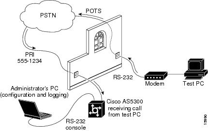
shows the test lab environment used for this test case. The test PC is running a terminal emulation program, such as Hyper Terminal. This program enables the test PC to make a modem-to-modem connection with the Cisco AS5300 via the PSTN/ISDN network.
Figure 2-3
Test Lab Environment
Step 1
hq-sanjose# debug modem csmModem Management Call Switching Module debugging is onhq-sanjose# debug isdn q931ISDN Q931 packets debugging is onhq-sanjose# terminal monitor % Console already monitors
Note
Step 2
If the modem successfully connects, you will see a connect message followed by the terminal service EXEC login prompt. This is displayed on the test PC.
atdt5551234CONNECT 24000/REL - MNPUser Access VerificationUsername: joe-admin Password: joe-passwordhq-sanjose>
Note
Step 3
The following comments apply to the debug output example:
(a)
The setup message is received. The bearer capability is a voice call as indicated by 0x8090A2. The calling party number is 5551111, the test PC's phone number. The called party number is 5551234, the access server's dialed hunt group number.(b)
Modem 1/1 is assigned to the incoming voice call.(c)
The call successfully connects as indicated by the fields "TX -> CONNECT" and "RX <- CONNECT_ACK."(d)
The integrated modem waits to negotiate carrier with the remote modem.*Mar 1 20:43:35.906: ISDN Se0:23: RX <- SETUP pd = 8 callref = 0x0001*Mar 1 20:43:35.906: Bearer Capability i = 0x8090A2*Mar 1 20:43:35.910: Channel ID i = 0xA98381*Mar 1 20:43:35.914: Calling Party Number i = '!', 0x80, '5551111'*Mar 1 20:43:35.918: Called Party Number i = 0xA1, '5551234'*Mar 1 20:43:35.934: EVENT_FROM_ISDN::dchan_idb=0x27C878, call_id=0xB, ces=0x1bchan=0x0, event=0x1, cause=0x0*Mar 1 20:43:35.938: VDEV_ALLOCATE: slot 1 and port 1 is allocated.*Mar 1 20:43:35.938: EVENT_FROM_ISDN:(000B): DEV_INCALL at slot 1 and port 1*Mar 1 20:43:35.942: CSM_PROC_IDLE: CSM_EVENT_ISDN_CALL at slot 1, port 1*Mar 1 20:43:35.946: Fast Ringing On at modem slot 1, port 1*Mar 1 20:43:35.966: ISDN Se0:23: TX -> CALL_PROC pd = 8 callref = 0x8001*Mar 1 20:43:35.970: Channel ID i = 0xA98381*Mar 1 20:43:35.978: ISDN Se0:23: TX -> ALERTING pd = 8 callref = 0x8001*Mar 1 20:43:36.742: Fast Ringing Off at modem slot 1, port 1*Mar 1 20:43:36.742: CSM_PROC_IC1_RING: CSM_EVENT_MODEM_OFFHOOK at slot 1, port1*Mar 1 20:43:36.754: ISDN Se0:23: TX -> CONNECT pd = 8 callref = 0x8001*Mar 1 20:43:36.782: ISDN Se0:23: RX <- CONNECT_ACK pd = 8 callref = 0x0001*Mar 1 20:43:36.798: EVENT_FROM_ISDN::dchan_idb=0x27C878, call_id=0xB, ces=0x1bchan=0x0, event=0x4, cause=0x0*Mar 1 20:43:36.802: EVENT_FROM_ISDN:(000B): DEV_CONNECTED at slot 1 and port 1*Mar 1 20:43:36.806: CSM_PROC_IC4_WAIT_FOR_CARRIER: CSM_EVENT_ISDN_CONNECTED atslot 1, port 1Every Q.931 message indicates whether the message was transmitted by the access server (TX ->) or received by the access server (RX <-). shows the most common message types used for opening and closing connections. Information elements exist within each message type, as described in .
ISDN setup messages contain different information elements. See .
Step 4
•
hq-sanjose# show userLine User Host(s) Idle Location* 0 con 0 joe-admin idle 02 tty 2 joe-admin Async interface 1•
hq-sanjose# show line 2Tty Typ Tx/Rx A Modem Roty AccO AccI Uses Noise Overruns2 TTY 115200/115200 - inout - - - 0 0 0/0Line 2, Location: "", Type: ""Length: 24 lines, Width: 80 columnsBaud rate (TX/RX) is 115200/115200, no parity, 1 stopbits, 8 databitsStatus: No Exit BannerCapabilities: Hardware Flowcontrol In, Hardware Flowcontrol OutModem Callout, Modem RI is CDModem state: Idlemodem(slot/port)=1/1, state=IDLEdsx1(slot/unit/channel)=NONE, status=VDEV_STATUS_UNLOCKEDGroup codes: 0Modem hardware state: CTS noDSR DTR RTSSpecial Chars: Escape Hold Stop Start Disconnect Activation^^x none - - noneTimeouts: Idle EXEC Idle Session Modem Answer Session Dispatch00:10:00 never none not setIdle Session Disconnect WarningneverLogin-sequence User Response00:00:30Autoselect Initial WaitTty Typ Tx/Rx A Modem Roty AccO AccI Uses Noise Overrunsnot setModem type is unknown.Session limit is not set.Time since activation: neverEditing is enabled.History is enabled, history size is 10.DNS resolution in show commands is enabledFull user help is disabledAllowed transports are lat pad telnet rlogin v120. Preferred is lat.No output characters are paddedNo special data dispatching characters•
hq-sanjose# show modem log 1/1Modem 1/1 Events Log:20:40:45: Startup Response: Microcom (Managed)Modem (boot) firmware = 2.2(8) (1.0(5))---- snip ----00:02:19: ISDN incoming calling number: 555111100:02:19: ISDN incoming called number: 555123400:02:13: Modem State event: Dialing/Answering00:02:13: Modem State event: Incoming ring00:02:13: Modem State event: Waiting for Carrier00:02:13: RS232 event: RTS DTR CTS DSR noDCD noRI* noTST00:02:01: Modem State event: Connected00:02:01: Connection event: TX/RX Speed = 33600/33600, Modulation = V34Direction = Answer, Protocol = reliable/LAPM, Compression = V42bis00:02:02: RS232 event: RTS DTR CTS DSR DCD* noRI noTST00:01:50: Modem Analog signal event: TX = -21, RX = -18, Signal to noise = 4300:00:15: DTR event: DTR Off00:00:15: Modem State event: Connected00:00:15: End connection event: Retransmits for EC block (TX/RX) = 0/0Duration = 0:01:43, Number of TX/RX char = 159/0Local Disc Reason = DTR DropRemote Disc Reason = Unknown00:00:15: Modem State event: Disconnecting00:00:15: DTR event: DTR On00:00:15: RS232 event: RTS DTR* CTS* DSR* noDCD* noRI* noTST*•
hq-sanjose# show modemInc calls Out calls Busied Failed No SuccMdm Usage Succ Fail Succ Fail Out Dial Answer Pct.1/0 0% 0 0 0 0 0 0 0 0%* 1/1 0% 1 0 0 0 0 0 0 100%1/2 0% 0 0 0 0 0 0 0 0%1/3 0% 0 0 0 0 0 0 0 0%1/4 0% 0 0 0 0 0 0 0 0%1/5 0% 0 0 0 0 0 0 0 0%1/6 0% 0 0 0 0 0 0 0 0%1/7 0% 0 0 0 0 0 0 0 0%1/8 0% 0 0 0 0 0 0 0 0%1/9 0% 0 0 0 0 0 0 0 0%1/10 0% 0 0 0 0 0 0 0 0%1/11 0% 0 0 0 0 0 0 0 0%---- snip -----•
hq-sanjose# show controller t1 0 call-countersT1 0:DS0's Active: 0DS0's Active High Water Mark: 0TimeSlot Type TotalCalls TotalDuration1 pri 1 00:01:302 pri 0 00:00:003 pri 0 00:00:004 pri 0 00:00:005 pri 0 00:00:006 pri 0 00:00:007 pri 0 00:00:008 pri 0 00:00:009 pri 0 00:00:0010 pri 0 00:00:0011 pri 0 00:00:0012 pri 0 00:00:0013 pri 0 00:00:0014 pri 0 00:00:0015 pri 0 00:00:0016 pri 0 00:00:0017 pri 0 00:00:0018 pri 0 00:00:0019 pri 0 00:00:0020 pri 0 00:00:0021 pri 0 00:00:0022 pri 0 00:00:0023 pri 0 00:00:00Total DS0's Active High Water Mark: 0•
hq-sanjose# modem at-mode 2/15You are now entering AT command mode on modem (slot 2 / port 15).Please type CTRL-C to exit AT command mode.at@e1MNP Class 10 K56flex ModemMODEM HW: OEM 2W United StatesFirmware Rev 3.3.20/85Bootstrap Rev 3.0.4DSP C36 Part/Rev 3635 4241DSP C58 Part/Rev 3635 2041DSP Controller Rev 42DSP Data Pump Rev 4.2NET ADDR: FFFFFFFFFFFFConnect Time 000:06:414 RTS 5 CTS 6 DSR 8 CD 20 DTR - RIDisconnect Remote - Local -Mod Type V.34TX/RX Spd 24000 26400 BPSTX/RX Spd Mask NA BFFF HexSymbol Rate 3200 HzTX/RX Carrier Freq 1829 1829 HzTX/RX States 16 16TX/RX NLE ON ONTX/RX Precoding ON ONTX/RX Shaping ON ONTX Preemphasis Index 0TX Lvl REG - 13 dBmTX Lvl RAM - 0 dBTX Lvl Reduct 1 dBTX Lvl - 14 dBmRX Lvl - 19 dBmS/NR 42S/DR 0EQM 1C00 HexAVG EQM 19BE HexLower/Upper Edge 150 3675 HzPhase Jitter Freq 139 HzPhase Jitter Amp 0.0 degFar Echo Lvl 138 NRound Trip Delay 0 msecDropouts > 5dB 0RTRNs Init/Accept 0 0RRENs Init/Accept 0 0BLER 0000 HexRBS Counter 0000 HexDigital Pad Detected 0 dBMax SECRXB 67Max SECTXB 67V8BIS STATUS NAKOKStep 8—Setting Up IP Address Pools
Create a pool of IP address to support remote nodes dialing in. As remote node devices connect, they request an IP address from the central site.
It is important to determine how your intranet/Internet backbone will route packets to the addresses in this pool. There are several ways to do this, such as using addresses off a subnet defined on the access server (for example, on the loopback or Ethernet interface).
Note
Configure
To set up the address pool, use the following commands beginning in global configuration mode:
1
Create loopback interface 0.
2
Assign an IP subnet and address to loopback 0. This subnet is used for the creation of your IP address pool1 .
3
Exit back to global configuration mode.
4
hq-sanjose(config)# ip local pool dialin_pool 10.1.2.2 10.1.2.97
Create a pool of IP addresses for assigning to the remote nodes2 .
5
hq-sanjose(config)# async-bootp dns-server 10.2.2.3 10.2.3.1
Specify the domain name servers on the network, which can be used for clients dialing in with PPP.
1 This subnet is now dedicated to this Cisco AS5300 for remote node support. This subnet cannot be used in other places in your network.
2 A remote LAN is typically a router that has a next hop address and its own IP subnet. It also requires IP routing support from the backbone, which is commonly accomplished with a static IP route. A remote node gets an IP address out of a central pool of IP addresses. Remote LANs and remote nodes are primarily differentiated by this IP addressing scheme. Remote LANs can appear as remote nodes by using PAT.
Verify
Enter the show ip local pool command to verify the configuration:
hq-sanjose# show ip local poolPool Begin End Free In use Cache Sizedialin_pool 10.1.2.2 10.1.2.97 96 0 20Step 9—Configuring the Group-Async Interface
The group-async interface is a template, which is used to control the configuration of all the async interfaces on the access server. Async interfaces are lines that are running in PPP mode. An async interface uses the same number as its corresponding line. Configuring the asynchronous interfaces as a group-async saves you time and configuration file size.
Configure
To configure the group-async interface, use the following commands beginning in global configuration mode:
Verify
Enter the show running command. After completing Steps 1 through 9, the configuration looks like this:
hq-sanjose# show runningBuilding configuration...Current configuration:!version 12.0service timestamps debug datetime msecservice timestamps log datetime msecservice password-encryption!hostname hq-sanjose!aaa new-modelaaa authentication login default localaaa authentication ppp default if-needed localenable secret 5 $1$.voA$9/8.Zoil3jeWJMP6hEE6U0!username joe-admin password 7 <removed>!async-bootp dns-server 10.2.2.3 10.2.3.1isdn switch-type primary-ni!!controller T1 0framing esfclock source line primarylinecode b8zspri-group timeslots 1-24!controller T1 1framing esfclock source line secondarylinecode b8zspri-group timeslots 1-24!controller T1 2framing esfclock source internallinecode b8zspri-group timeslots 1-24!controller T1 3framing esfclock source internallinecode b8zspri-group timeslots 1-24!interface Loopback0ip address 10.1.2.1 255.255.255.0no ip directed-broadcast!interface Ethernet0no ip addressno ip directed-broadcastno ip route-cacheno ip mroute-cacheshutdown!interface Serial0:23no ip addressno ip directed-broadcastisdn incoming-voice modemno fair-queueno cdp enable!interface Serial1:23no ip addressno ip directed-broadcastisdn incoming-voice modemno fair-queueno cdp enable!interface Serial2:23no ip addressno ip directed-broadcastisdn incoming-voice modemno fair-queueno cdp enable!interface Serial3:23no ip addressno ip directed-broadcastisdn incoming-voice modemno fair-queueno cdp enable!interface FastEthernet0ip address 10.1.1.10 255.255.255.0no ip directed-broadcastno ip route-cacheno ip mroute-cacheduplex autospeed auto!interface Group-Async1ip unnumbered Loopback0no ip directed-broadcastencapsulation pppasync mode interactivepeer default ip address pool dialin_poolno cdp enableppp authentication chap papgroup-range 1 96!ip local pool dialin_pool 10.1.2.2 10.1.2.97!!line con 0line 1 96autoselect during-loginautoselect pppmodem InOutline aux 0line vty 0 4!endStep 10—Testing Async PPP Connections
Now you are ready to send the first async PPP modem call into the Cisco AS5300. This step provides you with a picture of the test lab followed by debug output for a successful connection.
shows the test lab environment used for this test. A test PC makes a PPP modem-to-modem connection with the Cisco AS5300 via the PSTN/ISDN network.
Figure 2-4
Test Lab Environment
Step 1
hq-sanjose# debug ppp negotiationPPP protocol negotiation debugging is onhq-sanjose# debug ppp authenticationPPP authentication debugging is onhq-sanjose# debug modemModem control/process activation debugging is onhq-sanjose# debug ip peerIP peer address activity debugging is onhq-sanjose# show debugGeneral OS:Modem control/process activation debugging is onGeneric IP:IP peer address activity debugging is onPPP:PPP authentication debugging is onPPP protocol negotiation debugging is onhq-sanjose# terminal monitorStep 2
atdt5551234CONNECT 24000/REL - MNPUser Access VerificationUsername: joe-admin Password: joe-passwordhq-sanjose>Step 3
Note
The following comments apply to the debug output example, which spans over the next few pages. Locate the time stamps in the debug output then interpret the call behavior.
(a)
A modem call comes into the access server on TTY line 4.(b)
An incoming PPP frame is recognized, so PPP is launched on TTY line 4.(c)
The test PC gets assigned an IP address from the address pool set up on the access server. The address is 10.1.2.2.(d)
Interface async 4 comes up. After PPP launches, TTY line 4 becomes async interface 4.(e)
Incoming config request (I CONFREQ). The remote test PC requests a set of options to be negotiated. The PC asks the Cisco AS5300 to support the callback option.(f)
Outgoing config reject (O CONFREJ). The Cisco AS5300 rejects this option, because the access server is not configured to support Microsoft Callback in this case study.(g)
Incoming config request (I CONFREQ). The test PC requests a new set of options.(h)
Outgoing config acknowledgment (O CONFACK). The Cisco AS5300 accepts the new set of options.(i)
LCP is now open (LCP: State is Open). Both sides have acknowledged (CONFACK) the other side's configuration request (CONFREQ).(j)
After LCP negotiates, authentication starts. Authentication must happen before any network protocols, such as IP, are delivered. Both sides authenticate with the method negotiated during LCP. The Cisco AS5300 is authenticating the test PC using CHAP. The test PC is not authenticating the access server in this test case.(k)
Outgoing challenge from hq-sanjose.(l)
Incoming CHAP response from the test PC, which is shows the username joe-admin.(m)
An outgoing success is sent from the NAS—authentication is successful.(n)
PPP is up. The Cisco AS5300 PPP link is now open and available to negotiate any network protocols supported by both peers.(o)
The test PC requests support for Microsoft Point-to-Point Compression (MPPC). The Cisco AS5300 rejects this request. The access server's integrated modems already support hardware compression, and the Cisco IOS is not configured to support software compression.(p)
The primary and secondary DNS addresses are negotiated. At first, the test PC asks for 0.0.0.0. addresses. The access server sends out a CONFNAK and supplies the correct values. Values include an IP address from the pool, the primary DNS address, and the backup DNS address.(q)
The test PC sends an incoming request saying that the new values are accepted. Whenever the access server sends out a CONFNAK that includes values, the test PC still needs to come back and report acceptance of the new values.(r)
An outgoing CONFACK is sent for IPCP. The state is open for IPCP. A route is negotiated for the IPCP peer, which is 10.1.2.2.
Note
hq-sanjose#*Mar 1 21:34:56.958: TTY4: DSR came up*Mar 1 21:34:56.962: TTY4: Modem: IDLE->READY*Mar 1 21:34:56.970: TTY4: EXEC creation*Mar 1 21:34:56.978: TTY4: set timer type 10, 30 seconds*Mar 1 21:34:59.722: TTY4: Autoselect(2) sample 7E*Mar 1 21:34:59.726: TTY4: Autoselect(2) sample 7EFF*Mar 1 21:34:59.730: TTY4: Autoselect(2) sample 7EFF7D*Mar 1 21:34:59.730: TTY4: Autoselect(2) sample 7EFF7D23*Mar 1 21:34:59.734: TTY4 Autoselect cmd: ppp negotiate*Mar 1 21:34:59.746: TTY4: EXEC creation*Mar 1 21:34:59.746: TTY4: create timer type 1, 600 seconds*Mar 1 21:34:59.786: ip_get_pool: As4: using pool default*Mar 1 21:34:59.790: ip_get_pool: As4: returning address = 10.1.2.2*Mar 1 21:34:59.794: TTY4: destroy timer type 1 (OK)*Mar 1 21:34:59.794: TTY4: destroy timer type 0*Mar 1 21:35:01.798: %LINK-3-UPDOWN: Interface Async4, changed state to up*Mar 1 21:35:01.834: As4 PPP: Treating connection as a dedicated line*Mar 1 21:35:01.838: As4 PPP: Phase is ESTABLISHING, Active Open*Mar 1 21:35:01.842: As4 LCP: O CONFREQ [Closed] id 1 len 25*Mar 1 21:35:01.846: As4 LCP: ACCM 0x000A0000 (0x0206000A0000)*Mar 1 21:35:01.850: As4 LCP: AuthProto CHAP (0x0305C22305)*Mar 1 21:35:01.854: As4 LCP: MagicNumber 0x64E923A8 (0x050664E923A8)*Mar 1 21:35:01.854: As4 LCP: PFC (0x0702)*Mar 1 21:35:01.858: As4 LCP: ACFC (0x0802)*Mar 1 21:35:02.718: As4 LCP: I CONFREQ [REQsent] id 3 len 23*Mar 1 21:35:02.722: As4 LCP: ACCM 0x000A0000 (0x0206000A0000)*Mar 1 21:35:02.726: As4 LCP: MagicNumber 0x00472467 (0x050600472467)*Mar 1 21:35:02.726: As4 LCP: PFC (0x0702)*Mar 1 21:35:02.730: As4 LCP: ACFC (0x0802)*Mar 1 21:35:02.730: As4 LCP: Callback 6 (0x0D0306)*Mar 1 21:35:02.738: As4 LCP: O CONFREJ [REQsent] id 3 len 7*Mar 1 21:35:02.738: As4 LCP: Callback 6 (0x0D0306)*Mar 1 21:35:02.850: As4 LCP: I CONFREQ [REQsent] id 4 len 20*Mar 1 21:35:02.854: As4 LCP: ACCM 0x000A0000 (0x0206000A0000)*Mar 1 21:35:02.854: As4 LCP: MagicNumber 0x00472467 (0x050600472467)*Mar 1 21:35:02.858: As4 LCP: PFC (0x0702)*Mar 1 21:35:02.858: As4 LCP: ACFC (0x0802)*Mar 1 21:35:02.862: As4 LCP: O CONFACK [REQsent] id 4 len 20*Mar 1 21:35:02.866: As4 LCP: ACCM 0x000A0000 (0x0206000A0000)*Mar 1 21:35:02.870: As4 LCP: MagicNumber 0x00472467 (0x050600472467)*Mar 1 21:35:02.870: As4 LCP: PFC (0x0702)*Mar 1 21:35:02.874: As4 LCP: ACFC (0x0802)*Mar 1 21:35:03.842: As4 LCP: TIMEout: State ACKsent*Mar 1 21:35:03.842: As4 LCP: O CONFREQ [ACKsent] id 2 len 25*Mar 1 21:35:03.846: As4 LCP: ACCM 0x000A0000 (0x0206000A0000)*Mar 1 21:35:03.850: As4 LCP: AuthProto CHAP (0x0305C22305)*Mar 1 21:35:03.854: As4 LCP: MagicNumber 0x64E923A8 (0x050664E923A8)*Mar 1 21:35:03.854: As4 LCP: PFC (0x0702)*Mar 1 21:35:03.858: As4 LCP: ACFC (0x0802)*Mar 1 21:35:03.962: As4 LCP: I CONFACK [ACKsent] id 2 len 25*Mar 1 21:35:03.966: As4 LCP: ACCM 0x000A0000 (0x0206000A0000)*Mar 1 21:35:03.966: As4 LCP: AuthProto CHAP (0x0305C22305)*Mar 1 21:35:03.970: As4 LCP: MagicNumber 0x64E923A8 (0x050664E923A8)*Mar 1 21:35:03.974: As4 LCP: PFC (0x0702)*Mar 1 21:35:03.974: As4 LCP: ACFC (0x0802)*Mar 1 21:35:03.978: As4 LCP: State is Open*Mar 1 21:35:03.978: As4 PPP: Phase is AUTHENTICATING, by this end*Mar 1 21:35:03.982: As4 CHAP: O CHALLENGE id 1 len 26 from "hq-sanjose"*Mar 1 21:35:04.162: As4 CHAP: I RESPONSE id 1 len 26 from "joe-admin"*Mar 1 21:35:04.170: As4 AUTH: Started process 0 pid 47*Mar 1 21:35:04.182: As4 CHAP: O SUCCESS id 1 len 4*Mar 1 21:35:04.186: As4 PPP: Phase is UP*Mar 1 21:35:04.190: As4 IPCP: O CONFREQ [Not negotiated] id 1 len 10*Mar 1 21:35:04.194: As4 IPCP: Address 10.1.2.1 (0x03060A010201)*Mar 1 21:35:04.282: As4 IPCP: I CONFREQ [REQsent] id 1 len 28*Mar 1 21:35:04.282: As4 IPCP: CompressType VJ 15 slots CompressSlotID (0x0206002D0F01)*Mar 1 21:35:04.286: As4 IPCP: Address 0.0.0.0 (0x030600000000)*Mar 1 21:35:04.290: As4 IPCP: PrimaryDNS 0.0.0.0 (0x810600000000)*Mar 1 21:35:04.298: As4 IPCP: SecondaryDNS 0.0.0.0 (0x830600000000)*Mar 1 21:35:04.306: As4 IPCP: O CONFREJ [REQsent] id 1 len 10*Mar 1 21:35:04.310: As4 IPCP: CompressType VJ 15 slots CompressSlotID (0x0206002D0F01)*Mar 1 21:35:04.314: As4 CCP: I CONFREQ [Not negotiated] id 1 len 15*Mar 1 21:35:04.318: As4 CCP: MS-PPC supported bits 0x00000001 (0x120600000001)*Mar 1 21:35:04.318: As4 CCP: Stacker history 1 check mode EXTENDED (0x1105000104)*Mar 1 21:35:04.322: As4 LCP: O PROTREJ [Open] id 3 len 21 protocol CCP*Mar 1 21:35:04.326: As4 LCP: (0x80FD0101000F12060000000111050001)*Mar 1 21:35:04.330: As4 LCP: (0x04)*Mar 1 21:35:04.334: As4 IPCP: I CONFACK [REQsent] id 1 len 10*Mar 1 21:35:04.338: As4 IPCP: Address 10.1.2.1 (0x03060A010201)*Mar 1 21:35:05.186: %LINEPROTO-5-UPDOWN: Line protocol on Interface Async4, changed state to up*Mar 1 21:35:07.274: As4 IPCP: I CONFREQ [ACKrcvd] id 2 len 22*Mar 1 21:35:07.278: As4 IPCP: Address 0.0.0.0 (0x030600000000)*Mar 1 21:35:07.282: As4 IPCP: PrimaryDNS 0.0.0.0 (0x810600000000)*Mar 1 21:35:07.286: As4 IPCP: SecondaryDNS 0.0.0.0 (0x830600000000)*Mar 1 21:35:07.294: As4 IPCP: O CONFNAK [ACKrcvd] id 2 len 22*Mar 1 21:35:07.298: As4 IPCP: Address 10.1.2.2 (0x03060A010202)*Mar 1 21:35:07.302: As4 IPCP: PrimaryDNS 10.2.2.3 (0x81060A020203)*Mar 1 21:35:07.310: As4 IPCP: SecondaryDNS 10.2.3.1 (0x83060A020301)*Mar 1 21:35:07.426: As4 IPCP: I CONFREQ [ACKrcvd] id 3 len 22*Mar 1 21:35:07.430: As4 IPCP: Address 10.1.2.2 (0x03060A010202)*Mar 1 21:35:07.434: As4 IPCP: PrimaryDNS 10.2.2.3 (0x81060A020203)*Mar 1 21:35:07.442: As4 IPCP: SecondaryDNS 10.2.3.1 (0x83060A020301)*Mar 1 21:35:07.446: ip_get_pool: As4: validate address = 10.1.2.2*Mar 1 21:35:07.450: ip_get_pool: As4: using pool default*Mar 1 21:35:07.450: ip_get_pool: As4: returning address = 10.1.2.2*Mar 1 21:35:07.454: set_ip_peer_addr: As4: address = 10.1.2.2 (3) is redundant*Mar 1 21:35:07.458: As4 IPCP: O CONFACK [ACKrcvd] id 3 len 22*Mar 1 21:35:07.462: As4 IPCP: Address 10.1.2.2 (0x03060A010202)*Mar 1 21:35:07.466: As4 IPCP: PrimaryDNS 10.2.2.3 (0x81060A020203)*Mar 1 21:35:07.474: As4 IPCP: SecondaryDNS 10.2.3.1 (0x83060A020301)*Mar 1 21:35:07.478: As4 IPCP: State is Open*Mar 1 21:35:07.490: As4 IPCP: Install route to 10.1.2.2hq-sanjose# undebug allAll possible debugging has been turned off
Note
Step 11—Configuring DDR
Dial-on-demand routing (DDR) provides a mechanism to establish and maintain connectivity over a circuit switched network, such as the PSTN. DDR also supports remote LANs by maintaining IP routes to the remote sites when they are not connected.
Configure
To configure the dialer interfaces, use the following commands beginning in global configuration mode:
1
hq-sanjose(config)# interface dialer 1
hq-sanjose(config-if)# ip address 10.1.254.1 255.255.255.0Create interface dialer 1 and enable IP routing.
2
hq-sanjose(config-if)# exit
Exit back to global configuration mode.
3
hq-sanjose(config)# interface serial 0:23
hq-sanjose(config-if)# dialer rotary-group 1
hq-sanjose(config-if)# exitGroup serial 0's channels into dialer 1.
4
hq-sanjose(config)# interface serial 1:23
hq-sanjose(config-if)# dialer rotary-group 1
hq-sanjose(config-if)# exit
hq-sanjose(config)# interface serial 2:23
hq-sanjose(config-if)# dialer rotary-group 1
hq-sanjose(config-if)# exit
hq-sanjose(config)# interface serial 3:23
hq-sanjose(config-if)# dialer rotary-group 1
hq-sanjose(config-if)# exitGroup the remaining serial channels into dialer 1.
5
hq-sanjose(config)# interface dialer 1
Now with all the D channels grouped together, return to dialer 1.
6
hq-sanjose(config-if)# encapsulation ppp
Encapsulate the packets with PPP.
7
hq-sanjose(config-if)# peer default ip address pool dialin_pool
Assign an address pool to interface dialer 1. This step supports remote node ISDN devices, such as those running Easy IP and PAT1 .
8
hq-sanjose(config-if)# dialer in-band
Specify that this is an in-band dialer interface, which enables passing the phone number across the D channel.
9
hq-sanjose(config-if)# dialer idle-timeout 1800
Configure the idle timeout, which is set to 1800 seconds (30 minutes) in this example2 .
10
hq-sanjose(config-if)# dialer-group 2
Define the interesting packets, which are packets that reset the idle timer or trigger calls.
This dialer filter is defined by the dialer-list 2 command. See Step 173 .
11
hq-sanjose(config-if)# ppp multilink
Enable PPP multilink, which fragments and reassembles packets among bundled B channels.
12
hq-sanjose(config-if)# ppp authentication chap pap
Enable CHAP and PAP authentication. CHAP is used first. PAP is the second choice.
13
hq-sanjose(config-if)# no fair-queue
Disable fair queuing.
14
hq-sanjose(config-if)# no cdp enable
Disable the Cisco discovery protocol, unless you are using it for a specific purpose.
15
hq-sanjose(config-if)# no ip mroute-cache
Turn off multicast route caching.
16
hq-sanjose(config-if)# exit
Return to global configuration mode.
17
hq-sanjose(config)# dialer-list 2 protocol ip permit
Define a DDR dialer-list to allow any IP traffic to maintain the connection. Any IP packet will maintain the DDR session.
Minor or extensive tuning of your dialer list might be required to control costs in your environment.3
1 These users will also need a username and password.
2 Other environments might require shorter timeouts. The default is 120 seconds.
3 The dialer-group command and dialer-list command must use the same number. To monitor the idle timer value and the packets that reset it, use the debug dialer packet command and show dialer command.
Verify
To verify the configuration:
•
hq-sanjose# show dialerDialer1 - dialer type = IN-BAND SYNC NO-PARITYIdle timer (1800 secs), Fast idle timer (20 secs)Wait for carrier (30 secs), Re-enable (15 secs)Dial String Successes Failures Last called Last statusSerial0:0 - dialer type = ISDNIdle timer (1800 secs), Fast idle timer (20 secs)Wait for carrier (30 secs), Re-enable (15 secs)Dialer state is idleSerial0:1 - dialer type = ISDNIdle timer (1800 secs), Fast idle timer (20 secs)Wait for carrier (30 secs), Re-enable (15 secs)Dialer state is idleSerial0:2 - dialer type = ISDNIdle timer (1800 secs), Fast idle timer (20 secs)Wait for carrier (30 secs), Re-enable (15 secs)Dialer state is idle----- snip -----•
hq-sanjose# show runningBuilding configuration...Current configuration:!---- snip ----!interface Serial0:23no ip addressno ip directed-broadcastdialer rotary-group 1isdn incoming-voice modem!interface Serial1:23no ip addressno ip directed-broadcastdialer rotary-group 1isdn incoming-voice modem!interface Serial2:23no ip addressno ip directed-broadcastdialer rotary-group 1isdn incoming-voice modem!interface Serial3:23no ip addressno ip directed-broadcastdialer rotary-group 1isdn incoming-voice modem!---- snip ----!interface Dialer1ip address 10.1.254.1 255.255.255.0no ip directed-broadcastencapsulation pppno ip mroute-cachedialer in-banddialer idle-timeout 1800dialer-group 2peer default ip address pool dialin_poolno fair-queueno cdp enableppp authentication chap papppp multilink!dialer-list 2 protocol ip permit!---- snip ----Step 12—Configuring Definitions for Remote LAN Sites
You must configure additional parameters to enable synchronous PPP services for the remote sites. Each remote site must have the following three entries configured on the Cisco AS5300:
•
•
•
summarizes the critical parameters used by DDR, which works primarily at the addressing layer. These routes are stored in the routing table when the sites are not connected.
Configure
To enable the remote LANs to dial into the Cisco AS5300, use the following commands beginning in global configuration mode:
1
hq-sanjose(config)# username robo-austin password austin-pw
Specify the robo-austin username and password1 .
2
hq-sanjose(config)# ip route 10.1.4.0 255.255.255.0 10.1.254.4 permanent
Enable IP routing for the robo-austin subnet.
3
hq-sanjose(config)# username soho-tahoe password tahoe-pw
Specify the soho-tahoe username and password1.
4
hq-sanjose(config)# ip route 10.1.3.0 255.255.255.0 10.1.254.3 permanent
Enable IP routing for the soho-tahoe subnet.
5
hq-sanjose(config)# interface dialer 1
Enter interface dialer 1.
6
hq-sanjose(config-if)# dialer map ip 10.1.254.4 name robo-austin #
Create a dialer map entry to the robo-austin router2.
7
hq-sanjose(config-if)# dialer map ip 10.1.254.3 name soho-tahoe #
Create a dialer map entry to the soho-tahoe router2 .
1 Make sure to use your own usernames and passwords for the remote sites.
2 In this case study, hq-sanjose does not dial out to the remote sites. The pound sign (#) is used to map the remote site's name to the IP address.
Verify
Enter the show running command:
hq-sanjose# show runningBuilding configuration...Current configuration:!---- snip ----!username joe-admin password 7 <removed>username robo-austin password 7 <removed>username soho-tahoe password 7 <removed>!---- snip ----!interface Dialer1ip address 10.1.254.1 255.255.255.0no ip directed-broadcastencapsulation pppno ip mroute-cachedialer in-banddialer idle-timeout 1800dialer map ip 10.1.254.3 name soho-tahoe #dialer map ip 10.1.254.4 name robo-austin #dialer-group 2peer default ip address pool dialin_poolno fair-queueno cdp enableppp authentication chap papppp multilink!---- snip ----!ip local pool dialin_pool 10.1.2.2 10.1.2.97ip route 10.1.3.0 255.255.255.0 10.1.254.3 permanentip route 10.1.4.0 255.255.255.0 10.1.254.4 permanent!dialer-list 2 protocol ip permit!---- snip ----Tips
•
•
Note
Step 13—Configuring a Backhaul Routing Protocol
Assign a routing protocol and configure its related configuration parameters to integrate with the IP backbone. The dialer network uses static routing.
Configure
To configure the routing protocol, use the following commands beginning in global configuration mode:
Verify
To verify the configuration:
•
hq-sanjose# show ip eigrp topologyIP-EIGRP Topology Table for process 10Codes: P - Passive, A - Active, U - Update, Q - Query, R - Reply,r - Reply statusP 10.1.3.0/24, 1 successors, FD is 46226176via Redistributed (46226176/0)P 10.1.2.0/24, 1 successors, FD is 128256via Connected, Loopback0P 10.1.4.0/24, 1 successors, FD is 46226176via Redistributed (46226176/0)P 10.1.254.0/24, 1 successors, FD is 46226176via Connected, Dialer1•
hq-sanjose# show runningBuilding configuration...Current configuration:!---- snip ----!router eigrp 10redistribute staticpassive-interface Dialer1network 10.0.0.0no auto-summary!---- snip ----Step 14—Confirming the Final Running Configuration
Here is the final running configuration:
hq-sanjose# show runningBuilding configuration...Current configuration:!version 12.0service timestamps debug datetime msecservice timestamps log datetime msecservice password-encryption!hostname hq-sanjose!aaa new-modelaaa authentication login default localaaa authentication ppp default if-needed localenable secret 5 $1$.voA$9/8.Zoil3jeWJMP6hEE6U0!username joe-admin password 7 <removed>username robo-austin password 7 <removed>username soho-tahoe password 7 <removed>!async-bootp dns-server 10.2.2.3 10.2.3.1isdn switch-type primary-ni!!controller T1 0framing esfclock source line primarylinecode b8zspri-group timeslots 1-24!controller T1 1framing esfclock source line secondarylinecode b8zspri-group timeslots 1-24!controller T1 2framing esfclock source internallinecode b8zspri-group timeslots 1-24!controller T1 3framing esfclock source internallinecode b8zspri-group timeslots 1-24!interface Loopback0ip address 10.1.2.1 255.255.255.0no ip directed-broadcast!interface Ethernet0no ip addressno ip directed-broadcastno ip route-cacheno ip mroute-cacheshutdown!interface Serial0:23no ip addressno ip directed-broadcastdialer rotary-group 1isdn incoming-voice modem!interface Serial1:23no ip addressno ip directed-broadcastdialer rotary-group 1isdn incoming-voice modem!interface Serial2:23no ip addressno ip directed-broadcastdialer rotary-group 1isdn incoming-voice modem!interface Serial3:23no ip addressno ip directed-broadcastdialer rotary-group 1isdn incoming-voice modem!interface FastEthernet0ip address 10.1.1.10 255.255.255.0no ip directed-broadcastip summary-address eigrp 10 10.1.2.0 255.255.255.0no ip route-cacheno ip mroute-cacheduplex autospeed auto!interface Group-Async1ip unnumbered Loopback0no ip directed-broadcastencapsulation pppasync mode interactivepeer default ip address pool dialin_poolno cdp enableppp authentication chap papgroup-range 1 96!interface Dialer1ip address 10.1.254.1 255.255.255.0no ip directed-broadcastencapsulation pppno ip mroute-cachedialer in-banddialer idle-timeout 1800dialer map ip 10.1.254.3 name soho-tahoe #dialer map ip 10.1.254.4 name robo-austin #dialer-group 2peer default ip address pool dialin_poolno fair-queueno cdp enableppp authentication chap papppp multilink!router eigrp 10redistribute staticpassive-interface Dialer1network 10.0.0.0no auto-summary!ip local pool dialin_pool 10.1.2.2 10.1.2.97ip route 10.1.3.0 255.255.255.0 10.1.254.3 permanentip route 10.1.4.0 255.255.255.0 10.1.254.4 permanent!dialer-list 2 protocol ip permit!!line con 0line 1 96autoselect during-loginautoselect pppmodem InOutline aux 0line vty 0 4!end
CautionDo not expect your final configuration to look exactly like this one. You must localize for your own network environment. Additionally, most Cisco IOS software versions have different default settings. However, this final configuration provides a good basis for comparison.
Step 15—Saving the Configuration
Save the configuration to NVRAM by entering the copy running-config startup-config command.
Step 16—Testing Sync PPP Connections to Remote LANs
You must configure the remote ISDN routers before you can test DDR connections. For configuration tasks and end-to-end test examples, see the following chapters:
Step 17—Adding More Remote LAN Sites as Needed
After you bring up your remote LANs and remote nodes, you might decide to expand the solution to a larger dial implementation. The following key items must be configured on the Cisco AS5300 to support each additional remote LAN router:
•
•
•
Note
Table 2-5
dialer map ip peer-wan-addr name hostname #
A dialer map. Create a user entity in the security database for the remote site, which is appended to a dialer map1 .
ip route subnet mask wan-addr
A static route that points to the dialer map IP address.
username hostname password password
A username and password that matches the name on the dialer map.
1 If no phone number is used in the dialer map, this will prevent the central site from dialing out to the remote site.
Required Commands for Each Additional Site