Downloads |
 Feedback Feedback
|
Table Of Contents
Step 1—Configuring the Host Name, Password, and Time Stamps
Step 2—Configuring Local AAA Security
Step 3—Configuring the Ethernet Interface
Step 6—Testing Connections to the Cisco AS5300
Step 7—Confirming the Final Running Configuration
Step 8—Saving the Configuration
Cisco 1604 Configuration
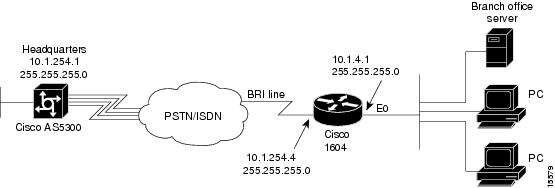
This chapter describes how to configure the Cisco 1604 to dial out to the Cisco AS5300.
Site Profile Characteristics
shows the network topology from the Cisco 1604's perspective.
Figure 3-1
Network Topology
provides detailed information about the end-to-end connection. This is the network administrator's top-level design table.
Table 3-1 Site Characteristics
Username
Password
IP Address1
IP Addressrobo-austin
austin-pw
10.1.254.4 255.255.255.0
10.1.4.1 255.255.255.0
Directory number = 5125554433
Cisco 1604
hq-sanjose
hq-sanjose-pw
10.1.254.1 255.255.255.0
10.1.1.10 255.255.255.0
4085551234
Cisco AS5300
1 The Cisco 1604's WAN default gateway is 10.1.254.1, which is the Cisco AS5300's dialer interface address.
Cisco IOS Release 12.0 is running inside the router. If the startup configuration is blank, the following screen is displayed at bootup. The automatic setup script is engaged. Enter no when you are asked the question, "Would you like to enter the initial configuration dialog? [yes]: no."
In this case study, the Cisco 1604 is manually configured. The automatic setup script is not used.
Note
To enhance readability throughout this chapter, the most important output fields are highlighted with bold font. The commands you enter are also bold but are preceded by a router prompt.
System Bootstrap, Version 11.1(7)AX [kuong (7)AX], RELEASE SOFTWARE (fc1)Copyright (c) 1994-1996 by cisco Systems, Inc.C1600 processor with 2048 Kbytes of main memoryprogram load complete, entry point: 0x4018060, size: 0x1da928Notice: NVRAM invalid, possibly due to write erase.%QUICC_ETHER-1-LOSTCARR: Unit 0, lost carrier. Transceiver problem?program loadcomplete, entry point: 0x8000060, size: 0x3f5f2cRestricted Rights LegendUse, duplication, or disclosure by the Government issubject to restrictions as set forth in subparagraph(c) of the Commercial Computer Software - RestrictedRights clause at FAR sec. 52.227-19 and subparagraph(c) (1) (ii) of the Rights in Technical Data and ComputerSoftware clause at DFARS sec. 252.227-7013.cisco Systems, Inc.170 West Tasman DriveSan Jose, California 95134-1706Cisco Internetwork Operating System SoftwareIOS (tm) 1600 Software (C1600-SY-L), Version 12.0(x)Copyright (c) 1986-1998 by cisco Systems, Inc.Compiled Tue 25-Aug-98 01:45 by xxxxImage text-base: 0x0802DA90, data-base: 0x02005000ROM: System Bootstrap, Version 11.1(10)AA, EARLY DEPLOYMENT RELEASE SOFTWARE (fc1)Router uptime is 10 minutesSystem restarted by reloadSystem image file is "flash:c1600-sy-l.120-x"cisco 1604 (68360) processor (revision C) with 17920K/512K bytes of memory.Processor board ID 08823977, with hardware revision 00972006Bridging software.X.25 software, Version 3.0.0.Basic Rate ISDN software, Version 1.1.1 Ethernet/IEEE 802.3 interface(s)1 ISDN Basic Rate interface(s)System/IO memory with parity disabled2048K bytes of DRAM onboard 16384K bytes of DRAM on SIMMSystem running from FLASH8K bytes of non-volatile configuration memory.12288K bytes of processor board PCMCIA flash (Read ONLY)--- System Configuration Dialog ---Would you like to enter the initial configuration dialog? [yes/no]: noWould you like to terminate autoinstall? [yes]: yesPress RETURN to get started!00:00:17: %QUICC_ETHER-1-LOSTCARR: Unit 0, lost carrier. Transceiver problem?00:00:17: %LINK-3-UPDOWN: Interface Ethernet0, changed state to up00:00:17: %LINK-3-UPDOWN: Interface Serial0, changed state to down00:00:17: %LINEPROTO-5-UPDOWN: Line protocol on Interface BRI0, changed state todown00:00:17: %LINEPROTO-5-UPDOWN: Line protocol on Interface BRI0:1, changed state to down00:00:17: %LINEPROTO-5-UPDOWN: Line protocol on Interface BRI0:2, changed state to down00:00:17: %LINEPROTO-5-UPDOWN: Line protocol on Interface Ethernet0, changed state to down00:00:17: %LINEPROTO-5-UPDOWN: Line protocol on Interface Serial0, changed stat to down00:00:44: %LINK-5-CHANGED: Interface BRI0, changed state to administratively down00:00:46: %LINK-5-CHANGED: Interface Serial0, changed state to administratively down00:00:46: %LINK-5-CHANGED: Interface Ethernet0, changed state to administratively down00:00:47: %IP-5-WEBINST_KILL: Terminating DNS processRouter>Overview of Tasks
Perform the following steps to configure the router:
•
•
•
•
•
•
•
•
Note
Step 1—Configuring the Host Name, Password, and Time Stamps
Assign a host name to the Cisco 1604, enable basic security, and turn on time stamping. Configuring a host name allows you to distinguish between different network devices. Enable passwords allow you to prevent unauthorized configuration changes. Time stamps help you trace debug output for testing connections. Not knowing exactly when an event occurs hinders you from examining background processes.
Configure
To configure the host name, enable password, and time stamps, use the following commands beginning in user EXEC mode:
1
Enter privileged EXEC mode.
2
Enter global configuration mode1 .
3
Assign a host name to the router.
This host name is typically used during authentication with the central site.
4
Enter a secret enable password, which secures privileged EXEC mode2 .
5
Encrypt passwords in the configuration file for greater security3 .
6
hq-sanjose(config)# service timestamps log datetime msecEnable millisecond time stamping on debug and logging output. Time stamps are useful for detailed access tracing.
1 As you are configuring the software, make sure that all logging dialog generated by the router is displayed on your terminal screen. If it is not, enter the terminal monitor EXEC command. If you are configuring the router via the console port, logging is automatically displayed.
2 Make sure to change "guessme" to your own secret password.
3 Additional measures should be used, as the passwords are not strongly encrypted by today's standards.
Verify
To verify the configuration:
•
robo-austin# show runningBuilding configuration...Current configuration:!version 12.0service timestamps debug uptimeservice timestamps log uptimeservice password-encryption!hostname robo-austin!enable secret 5 $1$og7B$nSwMZM0NBKTPhV09KVgxl1!interface Ethernet0no ip addressshutdown!interface Serial0no ip addressshutdown!interface BRI0no ip addressshutdown!ip classless!!line con 0line vty 0 4login!•
robo-austin# disablerobo-austin> enablePassword: letmeinrobo-austin# show privilegeCurrent privilege level is 15robo-austin#Tips
If you have trouble:
•
•
Step 2—Configuring Local AAA Security
The Cisco IOS security model to use on all Cisco devices is authentication, authorization, and accounting (AAA). AAA provides the primary framework through which you set up access control on the access server.
•
•
•
In this case study, the same authentication method is used on all interfaces. AAA is set up to use the local database configured on the router. This local database is created with the username configuration commands.
Note
Configure
To configure local AAA security, use the following commands beginning in global configuration mode:
1
robo-austin(config)# username joe-admin password joe-password
Create a local username for yourself1 .
This step prevents you from getting locked out of the router when you enable AAA.
2
robo-austin(config)# aaa new-model
Enable AAA access control.
This step immediately enables login and PPP authentication.
3
robo-austin(config)# aaa authentication login default local
Configure AAA to perform login authentication using the local username database.
The login keyword indicates authentication of EXEC (shell) users.
4
robo-austin(config)# aaa authentication ppp default if-needed local
Configure PPP authentication to use the local database if the session was not already authenticated by login.
1 Make sure to change "joe-admin" to your own username and "joe-password" to your own password.
Verify
To verify the configuration:
•
robo-austin# loginUser Access VerificationUsername: joe-adminPassword: joe-passwordrobo-austin#•
robo-austin# show runningBuilding configuration...Current configuration:!version 12.0service timestamps debug uptimeservice timestamps log uptimeservice password-encryption!hostname robo-austin!aaa new-modelaaa authentication login default localaaa authentication ppp default if-needed localenable secret 5 $1$og7B$nSwMZM0NBKTPhV09KVgxl1!username joe-admin password 7 <removed>!interface Ethernet0no ip addressshutdown!interface Serial0no ip addressshutdown!interface BRI0no ip addressshutdown!ip classless!!line con 0line vty 0 4!Step 3—Configuring the Ethernet Interface
Assign an IP address to the Ethernet interface. Test the interface by pinging it from a PC on the LAN.
Configure
To configure the Ethernet interface, use the following commands beginning in global configuration mode:
1
robo-austin(config)# interface ethernet 0
robo-austin(config-if)# ip address 10.1.4.1 255.255.255.0Configure the IP address and subnet mask on the Ethernet interface.
2
Bring up the interface1 .
1 This command changes the state of the interface from administratively down to up.
Verify
To verify the configuration:
•
The field "administratively down" means that the interface is configured with the shutdown command. To bring the interface up, you must enter the no shutdown command. The Status column refers to the ability to physically connect the network at layer 1 (needed for getting clocks and carrier signals). The Protocol column refers to the ability to see traffic flow, which typically occurs at the data link layer. For example, the Ethernet interface sends a loopback Ethernet packet out to itself via the Ethernet LAN.
robo-austin# show ip interface briefInterface IP-Address OK? Method Status ProtocolBRI0 unassigned YES unset administratively down downBRI0:1 unassigned YES unset administratively down downBRI0:2 unassigned YES unset administratively down downEthernet0 10.1.4.1 YES manual up upSerial0 unassigned YES unset administratively down downIn the next example, notice that the status is up but the protocol is down. The following logging message appears at 00:40:20: "Unit 0, lost carrier. Transceiver problem?."After the administrator plugs the Ethernet cable into the Ethernet port, the interface comes up. See 00:40:25.
robo-austin# show ip interface briefInterface IP-Address OK? Method Status ProtocolBRI0 unassigned YES unset administratively down downBRI0:1 unassigned YES unset administratively down downBRI0:2 unassigned YES unset administratively down downEthernet0 10.1.4.1 YES manual up downSerial0 unassigned YES unset administratively down downrobo-austin#00:40:20: %QUICC_ETHER-1-LOSTCARR: Unit 0, lost carrier. Transceiver problem?00:40:25: %LINEPROTO-5-UPDOWN: Line protocol on Interface Ethernet0, changed state to uprobo-austin#•
Microsoft(R) Windows 95(C)Copyright Microsoft Corp 1981-1996.C:\WINDOWS> ping 10.1.4.1Pinging 10.1.4.1 with 32 bytes of data:Reply from 10.1.4.1: bytes=32 time=3ms TTL=236Reply from 10.1.4.1: bytes=32 time=2ms TTL=236Reply from 10.1.4.1: bytes=32 time=3ms TTL=236Reply from 10.1.4.1: bytes=32 time=2ms TTL=236•
robo-austin# ping 10.1.4.2Type escape sequence to abort.Sending 5, 100-byte ICMP Echos to 10.1.4.2, timeout is 2 seconds:!!!!!Success rate is 100 percent (5/5), round-trip min/avg/max = 4/5/8 ms•
robo-austin# show interface ethernet 0Ethernet0 is up, line protocol is upHardware is QUICC Ethernet, address is 0060.834f.6626 (bia 0060.834f.6626)Internet address is 10.1.4.1/24MTU 1500 bytes, BW 10000 Kbit, DLY 1000 usec, rely 234/255, load 1/255Encapsulation ARPA, loopback not set, keepalive set (10 sec)ARP type: ARPA, ARP Timeout 04:00:00Last input 00:00:08, output 00:00:04, output hang neverLast clearing of "show interface" counters neverQueueing strategy: fifoOutput queue 0/40, 0 drops; input queue 0/75, 0 drops5 minute input rate 0 bits/sec, 0 packets/sec5 minute output rate 0 bits/sec, 0 packets/sec2 packets input, 644 bytes, 0 no bufferReceived 2 broadcasts, 0 runts, 0 giants, 0 throttles0 input errors, 0 CRC, 0 frame, 0 overrun, 0 ignored, 0 abort0 input packets with dribble condition detected28 packets output, 2905 bytes, 0 underruns25 output errors, 0 collisions, 2 interface resets0 babbles, 0 late collision, 0 deferred3 lost carrier, 0 no carrier0 output buffer failures, 0 output buffers swapped outStep 4—Configuring BRI
Enable BRI connectivity with the central office switch. PPP framing is used on the B channels. Dial-on-demand routing (DDR) is configured in the next section "Step 5—Configuring DDR."
Note
Configure
To configure BRI, use the following commands beginning in global configuration mode:
1
robo-austin(config)# isdn switch-type basic-ni1
Configure the ISDN switch type, which is basic-ni1 in this example.
2
robo-austin(config)# interface bri 0
robo-austin(config-if)# ip address 10.1.254.4 255.255.255.0Configure the IP address and subnet mask on the BRI interface.
3
robo-austin(config-if)# isdn spid1 51255544330101
robo-austin(config-if)# isdn spid2 51255544340101Configure your SPIDs, which are required by many switch types.
4
robo-austin(config-if)# encapsulation ppp
Enable PPP.
5
robo-austin(config-if)# no fair-queue
Disable fair queuing.
6
robo-austin(config-if)# ppp multilink
Enable PPP multilink.
7
robo-austin(config-if)# ppp authentication chap pap callin
Enable CHAP and PAP authentication on the interface during LCP negotiation.
The access server will first authenticate with CHAP. If CHAP is not used by the remote client, then PAP is tried. CHAP is requested first.1
8
Bring up the interface.2
1 You have the choice to authenticate the remote side on any connection. The callin keyword means that all outbound connection attempts made by the Cisco 1604 will not authenticate the remote peer. The remote peer is the device at the other end of the PPP link (Cisco AS5300). Only the calls that come into the Cisco 1604 will be authenticated.
2 The no shutdown command changes the state of the interface from administratively down to up.
Verify
•
This example shows the BRI0:1 and BRI0:2 states change to "down," because the previous state was "administratively down." The BRI0 D channel changes to "up" as it spoofs for the two B channels. After the D channel finds the B channels, the B channels change state to "up." The Cisco 1604 communicates with the telephone switch and receives its TEI numbers for its two B channels.
robo-austin(config-if)# no shutdownrobo-austin#00:45:01: %LINK-3-UPDOWN: Interface BRI0:1, changed state to down00:45:01: %LINK-3-UPDOWN: Interface BRI0:2, changed state to down00:45:01: %LINK-3-UPDOWN: Interface BRI0, changed state to uprobo-austin#00:45:02: %ISDN-6-LAYER2UP: Layer 2 for Interface BR0, TEI 100 changed to up00:45:02: %ISDN-6-LAYER2UP: Layer 2 for Interface BR0, TEI 101 changed to uprobo-austin(config-if)#•
robo-austin# show isdn statusGlobal ISDN Switchtype = basic-niISDN BRI0 interfacedsl 0, interface ISDN Switchtype = basic-niLayer 1 Status:ACTIVELayer 2 Status:TEI = 100, Ces = 1, SAPI = 0, State = MULTIPLE_FRAME_ESTABLISHEDTEI = 101, Ces = 2, SAPI = 0, State = MULTIPLE_FRAME_ESTABLISHEDSpid Status:TEI 100, ces = 1, state = 5(init)spid1 configured, no LDN, spid1 sent, spid1 validEndpoint ID Info: epsf = 0, usid = 2, tid = 1TEI 101, ces = 2, state = 5(init)spid2 configured, no LDN, spid2 sent, spid2 validEndpoint ID Info: epsf = 0, usid = 4, tid = 1Layer 3 Status:0 Active Layer 3 Call(s)Activated dsl 0 CCBs = 0Total Allocated ISDN CCBs = 0
Note
•
robo-austin# show ip interface briefInterface IP-Address OK? Method Status ProtocolBRI0 10.1.254.4 YES manual up upBRI0:1 unassigned YES unset down downBRI0:2 unassigned YES unset down downEthernet0 10.1.4.1 YES manual up upSerial0 unassigned YES unset administratively down down
Note
Tips
If you have trouble:
•
•
Step 5—Configuring DDR
Set up the DDR routing components. In most cases, a remote site with a single LAN will require a simple DDR configuration. DDR is the mechanism that supports the routing table and call control in a circuit switched environment.
DDR in this case study takes the standard dialer map approach. You must configure specific parameters to establish connectivity with the Cisco AS5300 using sync PPP. Parameters include a static route, username:password, and a dialer map.
Configure
To configure DDR, use the following commands beginning in global configuration mode:
1
robo-austin(config)# interface bri 0
Enter configuration mode for the BRI interface.
2
robo-austin(config-if)# dialer-group 2
Define the interesting packets that activate the ISDN connection. Interesting packets reset the idle timer and trigger dialing.
This dialer filter is defined by the dialer-list 2 command. See Step 7.
3
robo-austin(config-if)# no fair-queue
Disable fair queuing.
4
robo-austin(config-if)# no cdp enable
Disable the Cisco discovery protocol, unless you are using it for a specific purpose.
5
robo-austin(config-if)# dialer load-threshold 60 either
Configure the interface to bring up the second B channel when the bandwidth load exceeds 60/255.
6
robo-austin(config-if)# dialer map ip 10.1.254.1 name hq-sanjose 14085551234
robo-austin(config-if)# exitBuild a dialer map that maps to the Cisco AS5300's IP address, host name, and directory number.
The static route in Step 8 points to this dialer map.
7
robo-austin(config)# dialer-list 2 protocol ip permit
Define a DDR's dialer-list to allow any IP packets to establish and maintain calls.
8
robo-austin(config) ip route 0.0.0.0 0.0.0.0 10.1.254.1 permanent
Create a static route for the next hop, which is the Cisco AS5300's WAN port. IP address 10.1.254.1 is used on the Cisco AS5300's dialer interface.
This static route points at the dialer map on the access server's dialer interface.
9
robo-austin(config)# username hq-sanjose password austin-pw
When the Cisco AS5300 (hq-sanjose) authenticates the Cisco 1604 using CHAP, this password will be used by the Cisco 16041 .
10
robo-austin(config)# ip classless
Ensure that all unknown subnets use the default route.
1 On Cisco IOS devices the PPP name is determined by one of the following commands: hostname, sgbp group, ppp pap sent-username, or ppp chap hostname.
Verify
To verify the configuration:
•
robo-austin# show ip routeCodes: C - connected, S - static, I - IGRP, R - RIP, M - mobile, B - BGPD - EIGRP, EX - EIGRP external, O - OSPF, IA - OSPF inter areaN1 - OSPF NSSA external type 1, N2 - OSPF NSSA external type 2E1 - OSPF external type 1, E2 - OSPF external type 2, E - EGPi - IS-IS, L1 - IS-IS level-1, L2 - IS-IS level-2, * - candidate defaultU - per-user static route, o - ODRGateway of last resort is 10.1.254.1 to network 0.0.0.010.0.0.0/24 is subnetted, 2 subnetsC 10.1.4.0 is directly connected, Ethernet0C 10.1.254.0 is directly connected, BRI0S* 0.0.0.0/0 [1/0] via 10.1.254.1
Note
•
robo-austin# show dialerBRI0 - dialer type = ISDNDial String Successes Failures Last called Last status14085551234 0 0 never -0 incoming call(s) have been screened.0 incoming call(s) rejected for callback.BRI0:1 - dialer type = ISDNIdle timer (120 secs), Fast idle timer (20 secs)Wait for carrier (30 secs), Re-enable (15 secs)Dialer state is idleBRI0:2 - dialer type = ISDNIdle timer (120 secs), Fast idle timer (20 secs)Wait for carrier (30 secs), Re-enable (15 secs)Dialer state is idle•
robo-austin# show dialer mapStatic dialer map ip 10.1.254.1 name hq-sanjose (14085551234) on BRI0•
robo-austin# show runningBuilding configuration...Current configuration:!version 12.0service timestamps debug uptimeservice timestamps log uptimeservice password-encryption!hostname robo-austin!aaa new-modelaaa authentication login default localaaa authentication ppp default if-needed localenable secret 5 $1$aZ1D$wNO71EpS6y5zRYuW9qFEr.!username joe-admin password 0 6y5zRYuW9qFEr$wNO71EpS6$aZ1username hq-sanjose password 0 $wNO71EpS6y5zy5zRYuW9aZ1D$wisdn switch-type basic-ni!interface Ethernet0ip address 10.1.4.1 255.255.255.0!interface Serial0no ip addressshutdown!interface BRI0ip address 10.1.254.4 255.255.255.0encapsulation pppdialer map ip 10.1.254.1 name hq-sanjose 14085551234dialer load-threshold 60 eitherdialer-group 2isdn switch-type basic-niisdn spid1 51255544330101isdn spid2 51255544340101no cdp enableppp authentication chap pap callinppp multilinkhold-queue 75 in!ip classlessip route 0.0.0.0 0.0.0.0 10.1.254.1 permanent!dialer-list 2 protocol ip permit!line con 0line vty 0 4!endTips
•
•
•
•
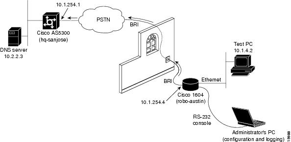
Step 6—Testing Connections to the Cisco AS5300
The test strategy is to ping the Cisco AS5300's WAN port then ping the backbone behind the access server. Cisco recommends you ping the domain name server (DNS) on the backbone, since this device should always be up and operational.
Pinging a next hop IP address can have complications in an IP-unnumbered environment. For example, complications arise when WAN interfaces are configured with IP unnumbered.
Note
shows the actual test lab environment used in this test case.
Figure 3-2 Test Lab Environment
Step 1
robo-austin# undebug allAll possible debugging has been turned offrobo-austin# terminal monitorrobo-austin# debug dialerDial on demand events debugging is onrobo-austin# debug isdn q931ISDN Q931 packets debugging is onrobo-austin# debug ppp negotiationPPP protocol negotiation debugging is onrobo-austin# debug ppp authenticationPPP authentication debugging is onrobo-austin# debug ip peerIP peer address activity debugging is onStep 2
robo-austin# show ip routeCodes: C - connected, S - static, I - IGRP, R - RIP, M - mobile, B - BGPD - EIGRP, EX - EIGRP external, O - OSPF, IA - OSPF inter areaN1 - OSPF NSSA external type 1, N2 - OSPF NSSA external type 2E1 - OSPF external type 1, E2 - OSPF external type 2, E - EGPi - IS-IS, L1 - IS-IS level-1, L2 - IS-IS level-2, * - candidate defaultU - per-user static route, o - ODRGateway of last resort is 10.1.254.1 to network 0.0.0.010.0.0.0/24 is subnetted, 2 subnetsC 10.1.4.0 is directly connected, Ethernet0C 10.1.254.0 is directly connected, BRI0S* 0.0.0.0/0 [1/0] via 10.1.254.1Step 3
robo-austin# show dialer mapStatic dialer map ip 10.1.254.1 name hq-sanjose (14085551234) on BRI0Step 4
robo-austin# ping 10.1.254.1Type escape sequence to abort.Sending 5, 100-byte ICMP Echos to 10.1.254.1, timeout is 2 seconds:.!!!!Success rate is 80 percent (4/5), round-trip min/avg/max = 116/182/372msrobo-austin#Step 5
(a)
The source and destination IP address of the DDR dial cause are displayed.
(s=10.1.254.4, d=10.1.254.1)(b)
Hq-sanjose's hunt group number is dialed.
(Attempting to dial 14085551234)(c)
ISDN Setup is transmitted.
(TX -> SETUP pd = 8 callref = 0x2F)(d)
A synchronous data bearer capability is displayed.
(Bearer Capability i = 0x8890)(e)
The outgoing LCP configuration request is made.
(BR0:1 LCP: O CONFREQ [Closed] id 42 len 28)(f)
The incoming LCP configuration request wants to authenticate with CHAP.
(AuthProto CHAP (0x0305C22305))(g)
The outgoing acknowledgment says this peer will do CHAP.
(LCP: O CONFACK [REQsent])(h)
Both PPP peers have received LCP CONFACK. LCP is now open.
(BR0:1 LCP: State is Open)(i)
Authentication phase is initiated by robo-austin.
(BR0:1 PPP: Phase is AUTHENTICATING, by the peer)(j)
Robo-austin accepts a CHAP challenge initiated by hq-sanjose. The device robo-austin is not authenticating hq-sanjose, which is the desired behavior for this scenario.
(BR0:1 CHAP: I CHALLENGE id 5 len 31 from "hq-sanjose")
(BR0:1 CHAP: O RESPONSE id 5 len 32 from "robo-austin")(k)
The robo-austin PPP peer is successfully authenticated by the hq-sanjose peer.
(BR0:1 CHAP: I SUCCESS id 5 len 4)(l)
MultiLink PPP uses a virtual-access interface to host the bundle.
(BR0:1 PPP: Phase is VIRTUALIZED)(m)
LCP on Virtual-Access2 is forced up as it was already negotiated on the physical interface. For more information, use the show interface virtual-access2 conf command and debug vtemp command.
(%LINK-3-UPDOWN: Interface Virtual-Access2, changed state to up)
(Vi2 PPP: Phase is UP)(n)
IPCP negotiation begins.
(Vi2 IPCP: O CONFREQ [Closed] id 1 len 10)
(Vi2 IPCP: Address 10.1.254.4 (0x03060A01FE04))(o)
IP can now be used across this PPP connection.
(Vi2 IPCP: I CONFACK [ACKsent] id 1 len 10)
(Vi2 IPCP: State is Open)(p)
A route is installed to 10.1.254.1 to match the IP address negotiated by the peer.
(BR0 IPCP: Install route to 10.1.254.1)(q)
The connection is made to hq-sanjose.
(Line protocol on Interface Virtual-Access2, changed state to up)
(Interface BRI0:1 is now connected to 14085551234 hq-sanjose)robo-austin# ping 10.1.254.1Type escape sequence to abort.Sending 5, 100-byte ICMP Echos to 10.1.254.1, timeout is 2 seconds:.!!!!Success rate is 80 percent (4/5), round-trip min/avg/max = 116/182/372msrobo-austin#08:03:55: BRI0: Dialing cause ip (s=10.1.254.4, d=10.1.254.1)08:03:55: BRI0: Attempting to dial 1408555123408:03:55: ISDN BR0: TX -> SETUP pd = 8 callref = 0x2F08:03:55: Bearer Capability i = 0x889008:03:55: Channel ID i = 0x8308:03:55: Keypad Facility i = '14085551234'08:03:55: ISDN BR0: RX <- CALL_PROC pd = 8 callref = 0xAF08:03:55: Channel ID i = 0x8908:03:55: ISDN BR0: RX <- CONNECT pd = 8 callref = 0xAF08:03:55: ISDN BR0: TX -> CONNECT_ACK pd = 8 callref = 0x2F08:03:55: %LINK-3-UPDOWN: Interface BRI0:1, changed state to up08:03:55: BR0:1 PPP: Treating connection as a callout08:03:55: BR0:1 PPP: Phase is ESTABLISHING, Active Open08:03:55: BR0:1 PPP: No remote authentication for call-out08:03:55: BR0:1 LCP: O CONFREQ [Closed] id 42 len 2808:03:55: BR0:1 LCP: MagicNumber 0x623E5C69 (0x0506623E5C69)08:03:55: BR0:1 LCP: MRRU 1524 (0x110405F4)08:03:55: BR0:1 LCP: EndpointDisc 1 Local(0x130E01726F626F2D61757374696E)08:03:55: BR0:1 LCP: I CONFREQ [REQsent] id 7 len 3208:03:55: BR0:1 LCP: AuthProto CHAP (0x0305C22305)08:03:55: BR0:1 LCP: MagicNumber 0xE16A73E6 (0x0506E16A73E6)08:03:55: BR0:1 LCP: MRRU 1524 (0x110405F4)08:03:55: BR0:1 LCP: EndpointDisc 1 Local(0x130D0168712D73616E6A6F7365)08:03:55: BR0:1 LCP: O CONFACK [REQsent] id 7 len 3208:03:55: BR0:1 LCP: AuthProto CHAP (0x0305C22305)08:03:55: BR0:1 LCP: MagicNumber 0xE16A73E6 (0x0506E16A73E6)08:03:55: BR0:1 LCP: MRRU 1524 (0x110405F4)08:03:55: BR0:1 LCP: EndpointDisc 1 Local(0x130D0168712D73616E6A6F7365)08:03:55: BR0:1 LCP: I CONFACK [ACKsent] id 42 len 2808:03:55: BR0:1 LCP: MagicNumber 0x623E5C69 (0x0506623E5C69)08:03:55: BR0:1 LCP: MRRU 1524 (0x110405F4)08:03:55: BR0:1 LCP: EndpointDisc 1 Local(0x130E01726F626F2D61757374696E).08:03:55: BR0:1 LCP: State is Open08:03:55: BR0:1 PPP: Phase is AUTHENTICATING, by the peer08:03:55: BR0:1 CHAP: I CHALLENGE id 5 len 31 from "hq-sanjose"08:03:55: BR0:1 CHAP: O RESPONSE id 5 len 32 from "robo-austin"08:03:55: BR0:1 CHAP: I SUCCESS id 5 len 408:03:55: BR0:1 PPP: Phase is VIRTUALIZED08:03:55: BR0:1 IPCP: Packet buffered while building MLP bundleinterface08:03:56: Vi2 PPP: Phase is DOWN, Setup08:03:56: %LINEPROTO-5-UPDOWN: Line protocol on Interface BRI0:1,changed state to up08:03:56: %LINK-3-UPDOWN: Interface Virtual-Access2, changed state to up08:03:56: Vi2 PPP: Treating connection as a callout08:03:56: Vi2 PPP: Phase is ESTABLISHING, Active Open08:03:56: Vi2 PPP: No remote authentication for call-out08:03:56: Vi2 LCP: O CONFREQ [Closed] id 1 len 2808:03:56: Vi2 LCP: MagicNumber 0x623E60D6 (0x0506623E60D6)08:03:56: Vi2 LCP: MRRU 1524 (0x110405F4)08:03:56: Vi2 LCP: EndpointDisc 1 Local(0x130E01726F626F2D61757374696E)08:03:56: Vi2 PPP: Phase is UP08:03:56: Vi2 IPCP: O CONFREQ [Closed] id 1 len 1008:03:56: Vi2 IPCP: Address 10.1.254.4 (0x03060A01FE04)08:03:56: Vi2 PPP: Pending ncpQ size is 108:03:56: BR0:1 IPCP: Redirect packet to Vi208:03:56: Vi2 IPCP: I CONFREQ [REQsent] id 1 len 1008:03:56: Vi2 IPCP: Address 10.1.254.1 (0x03060A01FE01)08:03:56: set_ip_peer_addr: Vi2: address = 10.1.254.1 (7)08:03:56: Vi2 IPCP: O CONFACK [REQsent] id 1 len 1008:03:56: Vi2 IPCP: Address 10.1.254.1 (0x03060A01FE01)08:03:57: Vi2 IPCP: I CONFACK [ACKsent] id 1 len 1008:03:57: Vi2 IPCP: Address 10.1.254.4 (0x03060A01FE04)08:03:57: Vi2 IPCP: State is Open08:03:57: dialer Protocol up for Vi208:03:57: BR0 IPCP: Install route to 10.1.254.108:03:57: %LINEPROTO-5-UPDOWN: Line protocol on InterfaceVirtual-Access2, changed state to up08:04:01: %ISDN-6-CONNECT: Interface BRI0:1 is now connected to14085551234 hq-sanjoseStep 6
robo-austin# ping 10.2.2.3Type escape sequence to abort.Sending 5, 100-byte ICMP Echos to 10.2.2.3, timeout is 2 seconds:!!!!!Success rate is 100 percent (5/5), round-trip min/avg/max = 4/7/12 msStep 7
robo-austin# show dialer mapStatic dialer map ip 10.1.254.1 name hq-sanjose (14085551234) on BRI0robo-austin# show dialerBRI0 - dialer type = ISDNDial String Successes Failures Last called Last status14085551234 1 0 00:00:30 successful0 incoming call(s) have been screened.0 incoming call(s) rejected for callback.BRI0:1 - dialer type = ISDNIdle timer (120 secs), Fast idle timer (20 secs)Wait for carrier (30 secs), Re-enable (15 secs)Dialer state is multilink memberDial reason: ip (s=10.1.254.4, d=10.1.254.1)Connected to 14085551234 (hq-sanjose)BRI0:2 - dialer type = ISDNIdle timer (120 secs), Fast idle timer (20 secs)Wait for carrier (30 secs), Re-enable (15 secs)Dialer state is idleVirtual-Access1 - dialer type = IN-BAND SYNC NO-PARITYRotary group 0, priority 0Idle timer (120 secs), Fast idle timer (20 secs)Wait for carrier (30 secs), Re-enable (15 secs)Dialer state is data link layer upTime until disconnect 105 secsConnected to 14085551234 (hq-sanjose)robo-austin# show ppp multilinkBundle hq-sanjose, 1 member, Master link is Virtual-Access1Dialer Interface is BRI00 lost fragments, 0 reordered, 0 unassigned, sequence 0x0/0x0 rcvd/sent0 discarded, 0 lost received, 1/255 loadMember Link: 1 (max not set, min not set)BRI0:1robo-austin# show interface bri 0:1BRI0:1 is up, line protocol is upHardware is BRIMTU 1500 bytes, BW 64 Kbit, DLY 20000 usec, rely 255/255, load 1/255Encapsulation PPP, loopback not set, keepalive set (10 sec)LCP Open, multilink OpenLast input 00:00:07, output 00:00:07, output hang neverLast clearing of "show interface" counters neverQueueing strategy: fifoOutput queue 0/40, 0 drops; input queue 0/75, 0 drops5 minute input rate 0 bits/sec, 0 packets/sec5 minute output rate 0 bits/sec, 0 packets/sec472 packets input, 13496 bytes, 0 no bufferReceived 469 broadcasts, 0 runts, 0 giants, 0 throttles0 input errors, 0 CRC, 0 frame, 0 overrun, 0 ignored, 0 abort504 packets output, 18013 bytes, 0 underruns0 output errors, 0 collisions, 0 interface resets0 output buffer failures, 0 output buffers swapped out104 carrier transitionsrobo-austin# show ip interface briefInterface IP-Address OK? Method Status ProtocolBRI0 10.1.254.4 YES manual up upBRI0:1 unassigned YES unset up upBRI0:2 unassigned YES unset down downEthernet0 10.1.3.1 YES manual up upSerial0 unassigned YES unset administratively down downVirtual-Access1 unassigned YES unset up uprobo-austin# show interface bri 0 1 2BRI0:1 is up, line protocol is upHardware is BRIMTU 1500 bytes, BW 64 Kbit, DLY 20000 usec, rely 255/255, load 1/255Encapsulation PPP, loopback not set, keepalive set (10 sec)LCP Open, multilink OpenLast input 00:00:00, output 00:00:00, output hang neverLast clearing of "show interface" counters neverQueueing strategy: fifoOutput queue 0/40, 0 drops; input queue 0/75, 0 drops5 minute input rate 0 bits/sec, 0 packets/sec5 minute output rate 0 bits/sec, 0 packets/sec478 packets input, 13592 bytes, 0 no bufferReceived 474 broadcasts, 0 runts, 0 giants, 0 throttles0 input errors, 0 CRC, 0 frame, 0 overrun, 0 ignored, 0 abort509 packets output, 18093 bytes, 0 underruns0 output errors, 0 collisions, 0 interface resets0 output buffer failures, 0 output buffers swapped out104 carrier transitionsBRI0:2 is down, line protocol is downHardware is BRIMTU 1500 bytes, BW 64 Kbit, DLY 20000 usec, rely 255/255, load 1/255Encapsulation PPP, loopback not set, keepalive set (10 sec)LCP Closed, multilink ClosedClosed: IPCPLast input 00:09:36, output 00:09:36, output hang neverLast clearing of "show interface" counters neverQueueing strategy: fifoOutput queue 0/40, 0 drops; input queue 0/75, 0 drops5 minute input rate 0 bits/sec, 0 packets/sec5 minute output rate 0 bits/sec, 0 packets/sec23 packets input, 722 bytes, 0 no bufferReceived 23 broadcasts, 0 runts, 0 giants, 0 throttles0 input errors, 0 CRC, 0 frame, 0 overrun, 0 ignored, 0 abort22 packets output, 727 bytes, 0 underruns0 output errors, 0 collisions, 0 interface resets0 output buffer failures, 0 output buffers swapped out2 carrier transitionsrobo-austin# show userLine User Host(s) Idle Location* 0 con 0 admin idle 0BR0:1 hq-sanjoe Sync PPP 00:00:38Step 7—Confirming the Final Running Configuration
Here is the final running configuration for the Cisco 1604:
robo-austin# show runningBuilding configuration...Current configuration:!version 12.0service timestamps debug uptimeservice timestamps log uptimeservice password-encryption!hostname robo-austin!aaa new-modelaaa authentication login default localaaa authentication ppp default if-needed localenable secret 5 $1$aZ1D$wNO71EpS6y5zRYuW9qFEr.!username joe-admin password 7 <removed>username hq-sanjose password 7 <removed>isdn switch-type basic-ni!!interface Ethernet0ip address 10.1.4.1 255.255.255.0!interface BRI0ip address 10.1.254.4 255.255.255.0encapsulation pppno ip route-cachedialer map ip 10.1.254.1 name hq-sanjose 14085551234dialer load-threshold 60 eitherdialer-group 2isdn switch-type basic-niisdn spid1 51255544330101isdn spid2 51255544340101no cdp enableppp authentication chap callinppp multilinkhold-queue 75 in!ip classlessip route 0.0.0.0 255.0.0.0 10.1.254.1 permanent!!dialer-list 2 protocol ip permit!line con 0line vty 0 4!endStep 8—Saving the Configuration
Save the configuration to NVRAM by entering the copy running-config startup-config command.