Feedback Feedback
|
Table Of Contents
Configuring the Cisco uBR10-MC5X20U/H BPE
Prerequisites for Configuring the Cisco uBR10-MC5X20U/H BPE
Restrictions for Configuring the Cisco uBR10-MC5X20U/H BPE
Information About Configuring the Cisco uBR10-MC5X20U/H BPE
Benefits of the Cisco uBR10-MC5x20U/H Broadband Processing Engine
How to Configure the Cisco uBR10-MC5x20U/H Broadband Processing Engine
Configuring and Enabling the Cable Interfaces
Monitoring and Maintaining the Cable Interface Line Card
Verifying a Downstream Port and Integrated Upconverter
Configuration Examples for the Cisco uBR10-MC5x20U/H Broadband Processing Engine
Cisco uBR10012 Router with Single Cisco uBR10-MC5x20U/H Broadband Processing Engine
Legacy N+1 Configurations for Backward Compatibility
HCCP Protect Interface Configuration Examples
Configuring the Cisco uBR10-MC5X20U/H BPE
First Published: 2002 (online only)
Last Updated: November 2007Document Revision History
The Cisco uBR10-MC5x20U/H Broadband Processing Engine is one of the new Broadband Processing Engine (BPE) series of cable interfaces that are available for the Cisco uBR10012 universal broadband router. The BPE cards provide increased performance and advanced radio frequency (RF) management, as well as innovative, integrated tools for sophisticated content, traffic and network management.
The Cisco uBR10-MC5X20U/H BPE is a cable interface line card for the Cisco uBR10012 router that performs cable modem termination system (CMTS) functions, such as:
•
Physical layer (PHY) radio frequency (RF) interface (upstream burst demodulation, downstream modulation, RF upconversion)
•
•
Featuring a highly integrated and robust RF front end and the industry's most advanced processing engine for DOCSIS- and EuroDOCSIS-based networks, the Cisco uBR10-MC5X20U/H BPE enables high-performance, reliable, and secure bidirectional transmission of IP packets over the cable plant for data, voice, and video services.
The Cisco uBR10-MC5X20U/H BPE supports HCCP N+1 Redundancy in the Cisco cable modem termination system (CMTS). N+1 Redundancy is made possible with the addition of the Cisco RF Switch to your cable headend network.
Together with the Cisco uBR10012 router, the Cisco RF Switch and the Cisco uBR10-MC5X20U/H BPE provide a fully redundant system that enables cable operators to achieve PacketCable system availability, minimize service disruptions, and simplify operations. N+1 Redundancy is an important step toward high availability on CMTS and telecommunications networks that use broadband media. Further information about HCCP N+1 Redundancy is described in the "Additional References" section.
Finding Support Information for Platforms and Cisco IOS Software Images
Use Cisco Feature Navigator to find information about platform support and Cisco IOS software image support. Access Cisco Feature Navigator at http://www.cisco.com/go/fn. You must have an account on Cisco.com. If you do not have an account or have forgotten your username or password, click Cancel at the login dialog box and follow the instructions that appear.
Contents
•
•
•
•
•
Prerequisites for Configuring the Cisco uBR10-MC5X20U/H BPE
Channel Plan
Determine a channel plan for your Cisco uBR10012 router and all of its cable interfaces.
Cisco IOS Release
The Cisco uBR10012 router must be running Cisco IOS Release 12.2(15)BC2 or later to support the Cisco uBR10-MC5X20U BPE, and Cisco IOS Release 12.3(17b)BC4 or later to support the Cisco uBR10-MC5X20H BPE.
Cisco uBR10012 Router Configuration
The Cisco uBR10012 router should be operational before beginning the procedures in this document to configure the Cisco uBR10-MC5X20U/H BPE. Complete a basic configuration of the Cisco uBR10012 router. This includes the following tasks as a strict minimum:
•
•
•
•
Bring up the router as described in the Configuring the Cable Modem Termination System for the First Time document.
DOCSIS and Internetwork Connectivity
Verify that your headend site includes all necessary servers to support DOCSIS and Internet connectivity, including Dynamic Host Configuration Protocol (DHCP), Time of Day (ToD), and TFTP servers.
Dual PRE1 or PRE2 Modules
The Cisco uBR10012 router must be using one or two Performance Routing Engine 1 (PRE1) or Performance Routing Engine 2(PRE2) modules to support the Cisco uBR10-MC5X20U/H BPE. The PRE module is not supported.
TCC+ Card
At least one Timing, Communication, and Control Plus (TCC+) card must be installed and operational in the Cisco uBR10012 router.
Restrictions for Configuring the Cisco uBR10-MC5X20U/H BPE
BPE Reconfiguration to Cisco uBR10-MC5X20
If you replace a Cisco uBR10-MC5X20U/H BPE with a Cisco uBR10-MC5X20U/H cable interface line card in the Cisco uBR10012 router chassis, you must reconfigure the line card.
Note
Domains for Downstream and Upstream Ports
The configuration of the downstream and upstream ports is fixed into the five domains that are listed in Table 2.
Symbol Rate Changes
When changing the symbol rate on the Cisco uBR10-MC5X20U/H BPE, the show controller cable upstream command may show "US phy SNR_estimate - Unknown" for a brief period of time. Wait a moment and reissue the command to obtain an accurate Signal-to-Noise Ratio (SNR) value.
Also refer to the show controllers cable command in the Cisco CMTS Cable Command Reference.
Unsupported Software Features for Cisco IOS Release 12.2(15)BC2 and Later Releases
The following software features are not supported for the Cisco uBR10-MC5X20U/H BPE with Cisco IOS Release 12.2(15)BC2 and later releases:
•
The load-interval interface configuration command is not supported on the Cisco uBR10-MC5X20U/H cable interface line card, although the command-line interface (CLI) accepts the command for these interfaces.
Unsupported Software Features for Cisco IOS Release 12.2(15)BC2 and Earlier Releases
The following software features are not supported for the Cisco uBR10-MC5X20U/H BPE with Cisco IOS Release 12.2(15)BC2 and earlier releases:
•
•
Unsupported Software Features for Cisco IOS Release 12.3(9) and Earlier Releases
The following software features are not supported for the Cisco uBR10-MC5X20U/H BPE with Cisco IOS Release 12.3(9) and earlier releases:
•
Information About Configuring the Cisco uBR10-MC5X20U/H BPE
The Cisco uBR10-MC5X20U/H BPE supports downstream and upstream traffic over a Data-over-Cable Service Interface Specification (DOCSIS)-based cable modem network. The card supports 6-MHz National Television Systems Committee (NTSC) channel operation, using standard (STD), Harmonic Related Carrier (HRC), or Incremental Related Carrier (IRC) frequency plans. The card supports downstream channels in the range from 54 to 860 MHz, an upstream range from 5 to 65 MHz, and a downstream center frequency configurable in 12.5-KHz increments; however, cable modems may be unable to locate the DOCSIS signal if the configured frequency is non-standard.
The Cisco uBR10-MC5X20U/H BPE contains five downstream ports and twenty upstream ports. Each downstream port includes an onboard integrated upconverter that generates an RF signal suitable for connection to a combiner and transmission on the coaxial cable network, without the need for any external upconverters.
In Cisco IOS Release 12.2(15)BC2 and later releases, the downstream ports support 64-Quadrature Amplitude Modulation (QAM) and 256-QAM, and the upstream ports support Quadrature Phase Shift Keying (QPSK), 8-QAM, 16-QAM, 32-QAM, and 64-QAM modulation, depending on the upstream's mode of operation. The upstream ports are initially configured to form five DOCSIS MAC domains, with each downstream port having four upstream ports. However, in Cisco IOS Release 12.2(15)BC2 and later releases, you can use the Virtual Interface feature and frequency stacking to configure upstream ports as desired.
Depending on the configuration, the Cisco uBR10-MC5X20U/H BPE supports either DOCSIS or Euro-DOCSIS operation:
•
•
Note
Within one chassis, however, you can have some cards that support Annex A, and some cards that support Annex B.
When operating in either the DOCSIS or EuroDOCSIS mode of operation, the Cisco uBR10-MC5X20U/H BPE supports the following types of networks:
•
•
•
Note
For information on installing the Cisco uBR10-MC5X20U/H card, see the Cisco uBR10-MC5X20S/U/H Cable Interface Line Card document on Cisco.com.
The Cisco uBR10-MC5X20U/H BPE supports all DOCSIS 1.1-specified Annex A, Annex B, and Euro-DOCSIS radio frequency (RF) data rates, channel widths, and modulation schemes. Table 1 shows the supported DOCSIS data rates.
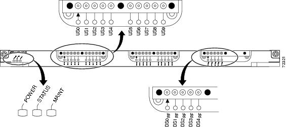
The Cisco uBR10-MC5X20U/H BPE is available withdense connectors. Each type of card contains a color-coded label that identifies the downstream and upstream ports. Figure 1 shows the front panels.
Figure 1 Cisco uBR10-MC5X20U/H BPE Front-Panel View (Dense Connectors)
The five downstream ports are labelled DS0 RF through DS4 RF. The RF label indicates that the port is outputting an RF signal from the port's integrated upconverter. The 20 upstream ports are labelled US0 through US19.
In Cisco IOS Release 12.2(15)BC2, each upstream (US) port is statically associated with a particular downstream (DS) port by default. Table 2 shows the association between the Cisco uBR10-MC5X20U/H BPE's physical port domains and the upstream and downstream ports associated with each domain. Table 2 also shows the interface label to use when referring to the port when using command-line interface (CLI) commands.
Note
Table 2 Interface-to-Port Mapping
Domain #1
DS0 RF
CX/Y/0
US0
CX/Y/0 U0
US1
CX/Y/0 U1
US2
CX/Y/0 U2
US3
CX/Y/0 U3
Domain #2
DS1 RF
CX/Y/1
US4
CX/Y/1 U0
US5
CX/Y/1 U1
US6
CX/Y/1 U2
US7
CX/Y/1 U3
Domain #3
DS2 RF
CX/Y/2
US8
CX/Y/2 U0
US9
CX/Y/2 U1
US10
CX/Y/2 U2
US11
CX/Y/2 U3
Domain #4
DS3 RF
CX/Y/3
US12
CX/Y/3 U0
US13
CX/Y/3 U1
US14
CX/Y/3 U2
US15
CX/Y/3 U3
Domain #5
DS4 RF
CX/Y/4
US16
CX/Y/4 U0
US17
CX/Y/4 U1
US18
CX/Y/4 U2
US19
CX/Y/4 U3
1 The X and Y in the CLI Cable Interface Label column refer to the physical card slot in which the card is installed. The value for X can range from 5 to 8, and the value for Y can be either 0 or 1.
For example, Table 2 shows the Cisco uBR10-MC5X20U/H BPE to be installed as follows:
•
•
•
•
Therefore, to configure upstream US14, you would specify upstream U2 on cable interface 5/1/3 (interface c5/1/3 command).
Benefits of the Cisco uBR10-MC5x20U/H Broadband Processing Engine
•
•
•
•
•
•
•
•
How to Configure the Cisco uBR10-MC5x20U/H Broadband Processing Engine
This section provides the following procedures to configure the Cisco uBR10-MC5X20U/H BPE for use in the Cisco uBR10012 universal broadband router chassis:
•
•
These procedures provide only the initial, basic configuration for the cable interfaces. For additional and advanced configuration, refer to the "Additional References" section.
Configuring and Enabling the Cable Interfaces
Use the following procedure to configure and enable the downstream and upstream cable interfaces on the Cisco uBR10-MC5X20U/H BPE.
SUMMARY STEPS
1.
2.
3.
4.
5.
6.
7.
8.
9.
10.
11.
or
cable upstream n spectrum-group group-number
12.
13.
14.
15.
16.
17.
18.
or
write memory
DETAILED STEPS
Step 1
Enables privileged EXEC mode.
•
Step 2
Enters global configuration mode.
Step 3
Enters interface configuration mode for the cable interface, where:
•
•
Step 4
Sets the fixed center frequency for the integrated upconverter for this domain's downstream RF carrier in Hz.
•
The usable range depends on whether the downstream is configured for DOCSIS or EuroDOCSIS operations:
–
–
Note
Step 5
(Optional) Sets the downstream modulation rate:
•
•
Step 6
(Optional) Sets the downstream interleave depth, in number of rows of codewords. The default is 32 rows.
Note
Step 7
(Optional) Sets the downstream channel ID. The default value is the unique unit number that is assigned by the CMTS.
•
Step 8
Sets the RF power output level, in dBmV, on the integrated upconverter.
•
Note
Step 9
Enables RF output on the integrated upconverter.
Step 10
no shutdownExample:Router (config-if)# no shutdownActivates the downstream port on a cable modem card for digital data transmission over the cable plant.
Step 11
Enters a fixed frequency of the upstream radio frequency (RF) carrier for an upstream port. This sets the center frequency for the upstream in Hz.
•
•
or
Assigns the upstream to a spectrum group that defines the valid range of upstream frequencies.
•
•
Step 12
Repeat Step 11 for each upstream port.
Repeat Step 11 for each upstream port, changing the port parameter from 0 through 3. You must configure each upstream with either a fixed center frequency or assign it to a spectrum group.
Step 13
(Optional) Sets how often a line card should train its noise-cancellation circuitry so as to adjust to noise levels on the upstream.
Optionally repeat this command for each upstream port, changing the port parameter from 0 through 3.
•
•
Note
Step 14
(Optional) Sets the input power level for the upstream in dBmV.
Optionally repeat this command for each upstream port, changing the port parameter from 0 through 3.
•
•
Channel Width (MHz) Range at CMTS (dBmV)
.2 -16 to 14
.4 -13 to 17
.8 -10 to 20
1.6 -7 to 23
3.2 -4 to 26
6.4 -1 to 29Step 15
Router (config-int) # no cable upstream 0 shutdownActivates the RF carrier on the upstream port. Each upstream port must be activated to enable upstream data from the cable modems on your network to the Cisco uBR10012 router.
•
Repeat this command for each upstream port, changing the port parameter from 0 through 3.
Note
Step 16
Repeat Steps 3-14 for each domain.
Repeat Steps 3-14 in this procedure for each domain, changing the downstream port from 0 through 4.
Step 17
Router(config-if)# exit
Exits interface configuration mode, and returns you to global configuration mode.
Step 18
copy running-config startup-configor
write memoryExample:Router# copy running-config startup-configor
Router# write memoryAfter configuring all domains, save your settings to the nonvolatile random access memory (NVRAM) to ensure that the system retains the settings after a power cycle
Examples
The following example shows how to complete a typical configuration for the first domain of the card installed in slot 8/0 in the Cisco uBR10012 chassis:
Router# enableRouter# configure terminalRouter(config)# interface cable 8/0/0Router(config-if)# cable bundle 1Router(config-if)# cable downstream annex BRouter(config-if)# cable downstream modulation 256qamRouter(config-if)# cable downstream interleave-depth 32Router(config-if)# cable downstream frequency 453000000Router(config-if)# cable downstream channel-id 0Router(config-if)# no cable downstream rf-shutdownRouter(config-if)# cable downstream rf-power 57Router(config-if)# cable upstream 0 connector 0Router(config-if)# cable upstream 0 frequency 10000000Router(config-if)# cable upstream 0 power-level 0Router(config-if)# cable upstream 0 channel-width 1600000Router(config-if)# cable upstream 0 minislot-size 4Router(config-if)# cable upstream 0 range-backoff 3 6Router(config-if)# cable upstream 0 modulation-profile 22Router(config-if)# no cable upstream 0 shutdownRouter(config-if)# cable upstream 1 connector 1Router(config-if)# cable upstream 1 frequency 20000000Router(config-if)# cable upstream 1 docsis-mode atdmaRouter(config-if)# cable upstream 1 power-level 0Router(config-if)# cable upstream 1 channel-width 1600000Router(config-if)# cable upstream 1 minislot-size 4Router(config-if)# cable upstream 1 range-backoff 3 6Router(config-if)# cable upstream 1 modulation-profile 225Router(config-if)# no cable upstream 1 shutdownRouter(config-if)# exitRouter(config)# exitRouter# write memoryRouter#
Note
Shutting Down the Interface
Before permanently removing a Cisco uBR10-MC5X20U/H BPE from the Cisco uBR10012 chassis, use the shutdown command to shut down and disable the interface. When you shut down an interface, it is designated administratively down in the show command displays.
Note
Use the following procedure to shut down an interface.
SUMMARY STEPS
1.
2.
3.
4.
5.
6.
7.
8.
DETAILED STEPS
Note
Monitoring and Maintaining the Cable Interface Line Card
The following sections describe the show commands that provide information about the Cisco uBR10-MC5X20U/H BPE:
•
Verifying a Downstream Port and Integrated Upconverter
Use the following procedure to display the status of a downstream port and its integrated upconverter on the Cisco uBR10-MC5X20U/H BPE.
SUMMARY STEPS
1.
2.
DETAILED STEPS
Examples
The following example shows a typical display that shows that the upconverter is enabled and configured for a frequency of 453 MHz:
Router# show controllers cable 6/0/0Interface Cable6/0/0Hardware is MC520SJIB version 60Cable6/0/0 Upconverter is Enabled Output is EnabledModel: 74-2094-02 Serial Number: 0WAV05530001 CLEI Code: EAIFBB0BAAHW Rev: PC2D0108 SW Rev: 007, NVRAM Rev: 006 ECI number 289389Downstream Frequency 453.0000 MHzRF Power 55.1 dBmvidb 0x60E18D30 MAC regs 0x20000000 SDRAM 0x28000000mac ring entries 32 bandwidth ring entries 128 tx ring entries 128 MAP tx ring entries 128MAC ring 0xF24F2A0 shadow 0x60E7A538 head 18 count 203634 full 0Bandwidth ring 0xF24F360 shadow 0x60E7A628 head 117 count 21237 full 0PCI low priority ring 0xF24F5A0 shadow 0x60E7A898 head 0 count 0 full 0High priority Tx ring 0xF24EE60 shadow 0x60E7A0C8 head 112 tail 114 count 1161886450 full 0Low priority Tx ring 0xF24EA20 shadow 0x60E79C58 head 126 tail 0 count 99648 full 0Timestamp is from local oscillatorthrottled 0 enabled 0 disabled 0Rx: spurious 0 framing_err 0 hcs_err 0 no_buffer 0 short_pkt 0no_enqueue 0 no_enp 0 miss_count 0 latency 0invalid_sid 0 invalid_mac 0 bad_ext_hdr_pdu 0 concat 0 bad-concat 0Tx: full 0 drop 0 stuck 0 latency 0MTx: full 0 drop 0 stuck 0 latency 0Slots 0 NoUWCollNoEngy 0 FECorHCS 2 HCS 0Req 0 ReqColl 0 ReqNoise 0 ReqNoEnergy 0ReqData 0 ReqDataColl 0 ReqDataNoise 0 ReqDataNoEnergy 0Rng 0 RngColl 0 RngNoise 0FECBlks 0 UnCorFECBlks 0 CorFECBlks 0MAP FIFO overflow 0, Rx FIFO overflow 0, No rx buf 0DS FIFO overflow 0, US FIFO overflow 0, US stuck 0Bandwidth Requests= 0x1DC0Piggyback Requests= 0x18A9Ranging Requests= 0x18530Timing Offset = 0x0Bad bandwidth Requests= 0x0Bad REG_ACK= 0x0No MAP buffer= 0x0No REG_RESP buffer= 0x0Cable6/0/0 Downstream is upFrequency 453.0000 MHz, Channel Width 6 MHz, 64-QAM, Symbol Rate 5.056941 MspsFEC ITU-T J.83 Annex B, R/S Interleave I=32, J=4Downstream channel ID: 0Dynamic Services Stats:DSA: 0 REQs 0 RSPs 0 ACKs0 Successful DSAs 0 DSA FailuresDSC: 0 REQs 0 RSPs 0 ACKs0 Successful DSCs 0 DSC FailuresDSD: 0 REQs 0 RSPs0 Successful DSDs 0 DSD FailuresDCC: 0 REQs 0 RSPs 0 ACKs0 Successful DCCs 0 DCC FailuresVerifying the Upstream Port
To verify the current configuration of an upstream port, perform these steps.
SUMMARY STEPS
1.
2.
DETAILED STEPS
Examples
The following example shows a typical display that shows that the upstream is configured for a frequency of 6.0 MHz, with a channel width of 1.6 MHz and 16-QAM modulation:
Router#show controllers cable 6/0/0 upstream 0Cable6/0/0 Upstream 0 is upFrequency 6.000 MHz, Channel Width 1.600 MHz, 16-QAM Symbol Rate 1.280 MspsSpectrum Group is overriddenSNR - Unknown - no modems online.Nominal Input Power Level 0 dBmV, Tx Timing Offset 0Ranging Backoff automatic (Start 3, End 6)Ranging Insertion Interval automatic (60 ms)Tx Backoff Start 3, Tx Backoff End 5Modulation Profile Group 21, 22Concatenation is enabledFragmentation is enabledpart_id=0x0952, rev_id=0x00, rev2_id=0x00nb_agc_thr=0x0000, nb_agc_nom=0x0000Range Load Reg Size=0x58Request Load Reg Size=0x0EMinislot Size in number of Timebase Ticks is = 8Minislot Size in Symbols = 64Bandwidth Requests = 0x0Piggyback Requests = 0x0Invalid BW Requests= 0x0Minislots Requested= 0x0Minislots Granted = 0x0Minislot Size in Bytes = 32Map Advance (Dynamic) : 2180 usecsUCD Count = 54528
Note
Configuration Examples for the Cisco uBR10-MC5x20U/H Broadband Processing Engine
This section provides typical configuration examples for the Cisco uBR10-MC5X20U/H BPE:
•
•
Cisco uBR10012 Router with Single Cisco uBR10-MC5x20U/H Broadband Processing Engine
The following is a portion of the configuration file for the Cisco uBR10012 router with a single Cisco uBR10-MC5X20U/H BPE:
interface Cable5/0/0cable downstream annex Bcable downstream modulation 64qamcable downstream interleave-depth 32no cable downstream rf-shutdown!cable upstream 0 frequency 11000000cable upstream 0 power-level 0no cable upstream 0 shutdown!cable upstream 1 frequency 32000000cable upstream 1 power-level 0no cable upstream 1 shutdown!cable upstream 2 frequency 26006000cable upstream 2 power-level 0no cable upstream 2 shutdown!cable upstream 3 frequency 7808000cable upstream 3 power-level 0cable upstream 3 channel-width 800000no cable upstream 3 shutdown!interface Cable5/0/1cable downstream annex Bcable downstream modulation 64qamcable downstream interleave-depth 32no cable downstream rf-shutdown!cable upstream 0 frequency 10000000cable upstream 0 power-level 0no cable upstream 0 shutdown!cable upstream 1 frequency 30000000cable upstream 1 power-level 0no cable upstream 1 shutdown!cable upstream 2 frequency 26000000cable upstream 2 power-level 0no cable upstream 2 shutdown!cable upstream 3 frequency 7004000cable upstream 3 power-level 0cable upstream 3 channel-width 800000no cable upstream 3 shutdown!interface Cable5/0/2cable downstream annex Bcable downstream modulation 64qamcable downstream interleave-depth 32no cable downstream rf-shutdown!cable upstream 0 frequency 10000000cable upstream 0 power-level 0no cable upstream 0 shutdown!cable upstream 1 frequency 30000000cable upstream 1 power-level 0no cable upstream 1 shutdown!cable upstream 2 frequency 22000000cable upstream 2 power-level 0no cable upstream 2 shutdown!cable upstream 3 frequency 7108000cable upstream 3 power-level 0cable upstream 3 channel-width 800000no cable upstream 3 shutdown!interface Cable5/0/3cable downstream annex Bcable downstream modulation 64qamcable downstream interleave-depth 32no cable downstream rf-shutdown!cable upstream 0 frequency 10000000cable upstream 0 power-level 0no cable upstream 0 shutdown!cable upstream 1 frequency 30000000cable upstream 1 power-level 0no cable upstream 1 shutdown!cable upstream 2 frequency 24000000cable upstream 2 power-level 0no cable upstream 2 shutdown!cable upstream 3 frequency 42000000cable upstream 3 power-level 0cable upstream 3 channel-width 3200000no cable upstream 3 shutdown!interface Cable5/0/4cable downstream annex Bcable downstream modulation 64qamcable downstream interleave-depth 32no cable downstream rf-shutdown!cable upstream 0 frequency 10000000cable upstream 0 power-level 0no cable upstream 0 shutdown!cable upstream 1 frequency 30000000cable upstream 1 power-level 0no cable upstream 1 shutdown!cable upstream 2 frequency 20000000cable upstream 2 power-level 0no cable upstream 2 shutdown!cable upstream 3 frequency 7008000cable upstream 3 power-level 0cable upstream 3 channel-width 800000no cable upstream 3 shutdownLegacy N+1 Configurations for Backward Compatibility
The following output from the Cisco IOS show running configuration command illustrates the configuration of N+1 Redundancy using the following CMTS:
•
•
•
The Protection mode affects the bitmaps of the Cisco RF Switch and CMTS configuration.
Note
•
•
Summary Steps for This Configuration
1.
2.
3.
4.
5.
Additional Configuration Notes
•
Router(config-if)# cable downstream modulation 256qam" as pertaining to slots 1-4 and their respective Protect slot, which is Protect 2.•
Router(config-if)# cable downstream interleave-depth 32." In the 4+1 mode the RF Switch slots 5-8 are considered to be slots 1-4 for configuration purposes.•
•
http://www.cisco.com/en/US/docs/cable/cmts/feature/guide/uFGnpls1.html
HCCP Working 1 Example
The following configuration example illustrates HCCP Working member 1 for five HCCP groups:
interface c8/0/0hccp 1 working 1hccp 1 channel-switch 1 rfswa rfswitch-group 10.10.10.10 44440400 1interface c8/0/1hccp 2 working 1hccp 2 channel-switch 1 rfswa rfswitch-group 10.10.10.10 11110100 1interface c8/0/2hccp 3 working 1hccp 3 channel-switch 1 rfswa rfswitch-group 10.10.10.10 00005000 1hccp 3 channel-switch 1 rfswb rfswitch-group 10.10.10.10 0000a080 1interface c8/0/3hccp 4 working 1hccp 4 channel-switch 1 rfswb rfswitch-group 10.10.10.10 88880800 1interface c8/0/4hccp 5 working 1hccp 5 channel-switch 1 rfswb rfswitch-group 10.10.10.10 22220200 1HCCP Working 2 Example
The following configuration example illustrates HCCP Working member 2 for five HCCP groups:
interface c8/1/0hccp 1 working 2hccp 1 channel-switch 2 rfswa rfswitch-group 10.10.10.10 44440400 2interface c8/1/1hccp 2 working 2hccp 2 channel-switch 2 rfswa rfswitch-group 10.10.10.10 11110100 2interface c8/1/2hccp 3 working 2hccp 3 channel-switch 2 rfswa rfswitch-group 10.10.10.10 00005000 2hccp 3 channel-switch 2 rfswb rfswitch-group 10.10.10.10 0000a080 2interface c8/1/3hccp 4 working 2hccp 4 channel-switch 2 rfswb rfswitch-group 10.10.10.10 88880800 2interface c8/1/4hccp 5 working 2hccp 5 channel-switch 2 rfswb rfswitch-group 10.10.10.10 22220200 2HCCP Working 3 Example
The following configuration example illustrates HCCP Working member 3 for five HCCP groups:
interface c7/0/0hccp 1 working 3hccp 1 channel-switch 3 rfswa rfswitch-group 10.10.10.10 44440400 3interface c7/0/1hccp 2 working 3hccp 2 channel-switch 3 rfswa rfswitch-group 10.10.10.10 11110100 3interface c7/0/2hccp 3 working 3hccp 3 channel-switch 3 rfswa rfswitch-group 10.10.10.10 00005000 3hccp 3 channel-switch 3 rfswb rfswitch-group 10.10.10.10 0000a080 3interface c7/0/3hccp 4 working 3hccp 4 channel-switch 3 rfswb rfswitch-group 10.10.10.10 88880800 3interface c7/0/4hccp 5 working 3hccp 5 channel-switch 3 rfswb rfswitch-group 10.10.10.10 22220200 3HCCP Working 4 Example
The following configuration example illustrates HCCP Working member 4 for five HCCP groups:
interface c7/1/0hccp 1 working 4hccp 1 channel-switch 4 rfswa rfswitch-group 10.10.10.10 44440400 4interface c7/1/1hccp 2 working 4hccp 2 channel-switch 4 rfswa rfswitch-group 10.10.10.10 11110100 4interface c7/1/2hccp 3 working 4hccp 3 channel-switch 4 rfswa rfswitch-group 10.10.10.10 00005000 4hccp 3 channel-switch 4 rfswb rfswitch-group 10.10.10.10 0000a080 4interface c7/1/3hccp 4 working 4hccp 4 channel-switch 4 rfswb rfswitch-group 10.10.10.10 88880800 4interface c7/1/4hccp 5 working 4HCCP Protect Interface Configuration Examples
The following examples illustrate the four HCCP Protect members for five HCCP groups:
interface c5/1/0hccp 1 protect 1 10.10.10.1hccp 1 channel-switch 1 rfswa rfswitch-group 10.10.10.10 44440400 1hccp 1 protect 2 10.10.10.1hccp 1 channel-switch 2 rfswa rfswitch-group 10.10.10.10 44440400 2hccp 1 protect 3 10.10.10.1hccp 1 channel-switch 3 rfswa rfswitch-group 10.10.10.10 44440400 3hccp 1 protect 4 10.10.10.1hccp 1 channel-switch 4 rfswa rfswitch-group 10.10.10.10 44440400 4interface c5/1/1hccp 2 protect 1 10.10.10.1hccp 2 channel-switch 1 rfswa rfswitch-group 10.10.10.10 11110100 1hccp 2 protect 2 10.10.10.1hccp 2 channel-switch 2 rfswa rfswitch-group 10.10.10.10 11110100 2hccp 2 protect 3 10.10.10.1hccp 2 channel-switch 3 rfswa rfswitch-group 10.10.10.10 11110100 3hccp 2 protect 4 10.10.10.1hccp 2 channel-switch 4 rfswa rfswitch-group 10.10.10.10 11110100 4interface c5/1/2hccp 3 protect 1 10.10.10.1hccp 3 channel-switch 1 rfswa rfswitch-group 10.10.10.10 00005000 1hccp 3 channel-switch 1 rfswb rfswitch-group 10.10.10.10 0000a080 1hccp 3 protect 2 10.10.10.1hccp 3 channel-switch 2 rfswa rfswitch-group 10.10.10.10 00005000 2hccp 3 channel-switch 2 rfswb rfswitch-group 10.10.10.10 0000a080 2hccp 3 protect 3 10.10.10.1hccp 3 channel-switch 3 rfswa rfswitch-group 10.10.10.10 00005000 3hccp 3 channel-switch 3 rfswb rfswitch-group 10.10.10.10 0000a080 3hccp 3 protect 4 10.10.10.1hccp 3 channel-switch 4 rfswa rfswitch-group 10.10.10.10 00005000 4hccp 3 channel-switch 4 rfswb rfswitch-group 10.10.10.10 0000a080 4interface c5/1/3hccp 4 protect 1 10.10.10.1hccp 4 channel-switch 1 rfswb rfswitch-group 10.10.10.10 88880800 1hccp 4 protect 2 10.10.10.1hccp 4 channel-switch 2 rfswb rfswitch-group 10.10.10.10 88880800 2hccp 4 protect 3 10.10.10.1hccp 4 channel-switch 3 rfswb rfswitch-group 10.10.10.10 88880800 3hccp 4 protect 4 10.10.10.1hccp 4 channel-switch 4 rfswb rfswitch-group 10.10.10.10 88880800 4interface c5/1/4hccp 5 protect 1 10.10.10.1hccp 5 channel-switch 1 rfswb rfswitch-group 10.10.10.10 22220200 1hccp 5 protect 2 10.10.10.1hccp 5 channel-switch 2 rfswb rfswitch-group 10.10.10.10 22220200 2hccp 5 protect 3 10.10.10.1hccp 5 channel-switch 3 rfswb rfswitch-group 10.10.10.10 22220200 3hccp 5 protect 4 10.10.10.1hccp 5 channel-switch 4 rfswb rfswitch-group 10.10.10.10 22220200 4Additional References
The following sections provide references related to configuring the Cisco uBR10-MC5X20U/H broadband processing engine:
Related Documents
Cisco uBR10012 router installation and configuration
•
•
•
Cisco IOS Software References
•
•
Cisco uBR10-MC5x20U/H Broadband Processing Engine Installation
•
•
•
High Availability
(N+1 Redundancy)•
Spectrum Management and Modulation Profiles
•
Note
You must also assign modulation profiles to each upstream interface and define the spectrum management characteristics, following general spectrum management configuration guidelines contained in this document•
Note
Standards
MIBs
RFCs
Technical Assistance
This document is to be used in conjunction with the documents listed in the "Additional References" section.
Copyright © 2002-2006, Cisco Systems, Inc.
All rights reserved.