Cabling the Cisco uBR10-MC5X20S/U/H Cable Interface Line Card with UCH2 - Quick Start Guide
Available Languages
Table Of Contents
Cabling the Cisco uBR10-MC5X20S/U/H Cable Interface Line Card with Universal Cable Holder—UCH2
Obtaining Documentation and Submitting a Service Request
Quick Start Guide
Cabling the Cisco uBR10-MC5X20S/U/H Cable Interface Line Card with Universal Cable Holder—UCH2
Last Updated: May 14, 2009OL-24878-01Contents
This document contains the following information:
Feature Description
The Cisco uBR10-MC5X20S, U and H cable interface line cards use 75-ohm precision video coax cables and 75-ohm MCX connectors to connect to the CMTS.
This document describes how to install and remove cables and the second generation universal cable holder (UCH2).
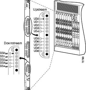
Figure 1 shows the cards in a Cisco uBR10012 router.
Figure 1 Cisco uBR10-MC5X20S/U/H Cards

Note
Quad-shield coaxial cable bundles for the Cisco uBR10-MC5X20S/U/H cable interface line card can be purchased from Cisco, with the Universal Cable Holders (UCH) already connected to the coaxial cable bundles. Alternatively, custom-length quad-shield coaxial cable bundles can be purchased from third party vendors, with the UCH either connected to the cable bundles or provided as separate components.
The cable bundle for RF card to HFC plant has five 5-bundle MCX connectors attached to three UCH2 units on one end, and F connectors attached to the other end. The cable bundle is 9.84 feet (3 m) long and is referred to by the Cisco part number CAB-RFSW520QTIMF2.
Note
Figure 2 shows the cable bundle for Cisco uBR10-MC5X20S/U/H cable interface line card to hybrid fiber-coaxial (HFC) plant that has 25 F connectors attached to one end and three UCH2 units attached to the other end. This cable is 9.84 feet (3 m) long and the part number is CAB-RFSW520QTIMF2.
Figure 2 Cable Bundle with UCH2 Units and F Connectors
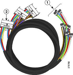
Figure 3 shows the cable bundle for Cisco uBR10-MC5X20S/U/H cable interface line card to RF switch that has three UCH2 units attached to one end and two RF switch header blocks attached to the other end. This cable is 3.2 feet (1 m) long and the part number is CAB-RFSW520QTIMM2.
Figure 3 Cable Bundle with UCH2 Units and RF Switch Header Blocks
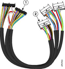
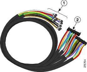
Figure 4 shows the cable bundle for RF switch to HFC plant that has two RF switch header blocks attached to one end and 25 F connectors attached to the other end. This cable is 9.84 feet (3 m) long and the part number is CAB-RFSW520QTPMF2.
Figure 4 Cable Bundle with RF Switch Header Blocks and F Connectors
Note
Tools required for cable installation include:
•
Also see "Tool Manufacturers and Part Numbers."
Note
Installing the Cables
The UCH must be used for all Cisco uBR10-MC5X20S/U/H line card cable connections. Failure to use the UCH may cause permanent damage to the line card connectors and result in low or no RF output.
Step 1
Step 2
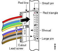
We recommend that the cables be installed in the UCH as shown in Table 1 and Table 2.

Caution
Note
Table 1 MC5X20 Dual/Qual Shielded Cable Ports and Cable Colors
User DefinedUS1 0
Red
US10
Grey
DS2 0
Red
US1
White
US11
Brown
DS1
White
US2
Blue
US12
Red
DS2
Blue
US3
Green
US13
White
DS3
Green
US4
Yellow
US14
Blue
DS4
Yellow
US5
Violet
US15
Green
—
—
US6
Orange
US16
Yellow
—
—
US7
Black
US17
Violet
—
—
US8
Grey
US18
Orange
—
—
US9
Brown
US19
Black
—
—
1 US = upstream
2 DS = downstream
Table 2 Legacy 5-Color MC5X20 Quad-Shielded Cable Ports and Cable Colors
User DefinedUS1 0
Red
US10
Red
DS2 0
Red
US1
White
US11
White
DS1
White
US2
Blue
US12
Blue
DS2
Blue
US3
Green
US13
Green
DS3
Green
US4
Yellow
US14
Yellow
DS4
Yellow
US5
Red
US15
Red
—
—
US6
White
US16
White
—
—
US7
Blue
US17
Blue
—
—
US8
Green
US18
Green
—
—
US9
Yellow
US19
Yellow
—
—
1 US = upstream
2 DS = downstream
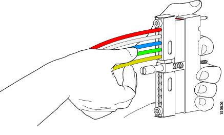
Step 3
Caution
Figure 5 Inserting a Cable in the UCH2
Step 4
Step 5
Step 6
Installing the UCH
After the cables are installed in the UCH, perform the following steps to prevent ESD damage to the line card.
Note
Step 1
Step 2
Step 3
Step 4
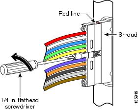
Figure 6 Installing the UCH
Step 5
Step 6
Step 7
Caution
The UCH is fully engaged when the semi-circles on the shroud show metal and the red and black lines are completely covered. See Figure 6.
Removing the UCH
Step 1
Step 2
Step 3
Note
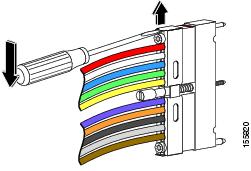
Figure 7 Removing the UCH
Removing the Cables
Step 1
Step 2
(Make sure the lock bar is completely open or the cables will not release.)
Caution
Step 3
Figure 8 Sliding Open the Lock Bar
Troubleshooting
Check the following:
1.
2.
3.
If downstream RF power measurements are made, use these ESD precautions to prevent damage to the product:
1.
2.
3.
4.
Contact Cisco TAC for further information:
Tool Manufacturers and Part Numbers
Related Documentation
•
•
http://www.cisco.com/en/US/products/
Obtaining Documentation and Submitting a Service Request
For information on obtaining documentation, submitting a service request, and gathering additional information, see the monthly What's New in Cisco Product Documentation, which also lists all new and revised Cisco technical documentation, at:
http://www.cisco.com/en/US/docs/general/whatsnew/whatsnew.html
Subscribe to the What's New in Cisco Product Documentation as a Really Simple Syndication (RSS) feed and set content to be delivered directly to your desktop using a reader application. The RSS feeds are a free service. Cisco currently supports RSS Version 2.0.
This document is to be used in conjunction with the documents listed in the "Related Documentation" section.
Cisco and the Cisco logo are trademarks or registered trademarks of Cisco and/or its affiliates in the U.S. and other countries. To view a list of Cisco trademarks, go to this URL: www.cisco.com/go/trademarks. Third-party trademarks mentioned are the property of their respective owners. The use of the word partner does not imply a partnership relationship between Cisco and any other company. (1110R)
Any Internet Protocol (IP) addresses and phone numbers used in this document are not intended to be actual addresses and phone numbers. Any examples, command display output, network topology diagrams, and other figures included in the document are shown for illustrative purposes only. Any use of actual IP addresses or phone numbers in illustrative content is unintentional and coincidental.
© 2009 Cisco Systems, Inc. All rights reserved.
 Feedback
Contact Cisco
- Open a Support Case

- (Requires a Cisco Service Contract)