Cisco uBR10-MC5X20S/U/H Cable Interface Line Card Hardware Installation Guide
Available Languages
Table Of Contents
Cisco uBR10-MC5X20S/U/H Cable Interface
Line Card Hardware Installation GuideInformation on Cisco uBR10-MC5X20S/U/H Line Cards
Safety Information and Warnings
Electrical Equipment Guidelines
Preventing Electrostatic Discharge Damage
Installing and Replacing a Cisco uBR10-MC5X20S/U/H Cable Interface Line Card
Unpacking the Cisco uBR10-MC5X20S/U/H Cable Interface Line Card
Installing the Cisco uBR10-MC5X20S/U/H Cable Interface Line Card in the Card Slot
Removing the Cisco uBR10-MC5X20S/U/H Cable Interface Line Card from the Card Slot
Replacing the SODIMM on the Cisco uBR10-MC5x20H Line Card
Using the Universal Cable Holder on Cisco uBR10-MC5X20 Line Cards
Installing the UCH on the Cisco uBR10-MC5X20S/U/H Card
Removing the UCH from the Cisco uBR10-MC5X20S/U/H Cable Interface Line Card
Installing or Replacing Cables in the UCH1
Installing or Replacing Cables in the UCH2
Adding Heat-Shrink Tubing to Custom Built Cables
Troubleshooting the Cisco uBR10-MC5X20S/U/H Cable Interface Line Card Installation
Downstream RF Power Measurement Caution
Technical Specifications and Component Part Numbers
Physical Specifications and Compliance Information
RF Specifications Specific to Cisco uBR-MC5X20U and H
Obtaining Documentation and Submitting a Service Request
Cisco uBR10-MC5X20S/U/H Cable Interface
Line Card Hardware Installation Guide
First Published: September 2003
Last Updated: April, 2012Document Revision History
Purpose
The purpose of this document is to provide installation, removal, and troubleshooting information for the Cisco uBR-MC5x20 S/U/H line cards in the Cisco uBR10012 universal broadband router.
Audience
This document is intended for use by a field service engineer who is familiar with Cisco products and headend cable installation procedures.
WarningOnly trained and qualified personnel should be allowed to install, replace, or service this equipment. Statement 1030.
Contents
•
•
•
–
–
–
•
•
–
–
–
–
•
•
•
•
Information on Cisco uBR10-MC5X20S/U/H Line Cards
The Cisco uBR10-MC5X20S, U and H cable interface line cards are 20 by 16 inch cards designed specifically for the Cisco uBR10012 router. These cards transmit and receive RF signals between the subscriber and the headend over hybrid fiber-coaxial (HFC) system.
Upstream data, from the subscriber, comes through the upstream ports (US0-US19) on the Cisco uBR10-MC5X20S/U/H cable interface line card. The line card processes and configures the data and sends it across the backplane to the WAN/backhaul card and out to the Internet.
Downstream data, to the subscriber, comes from the Internet through the WAN/backhaul card, and across the backplane to the Cisco uBR10-MC5X20S/U/H cable interface line card. The Cisco uBR10-MC5X20S/U/H card processes and configures the data and sends it out through the appropriate downstream port (DS0-DS4) to be combined with the rest of the downstream signals in the headend.
The Cisco uBR10-MC5X20S/U line cards use burst receivers that report unequalized Modulation Error Ratio (MER). The Cisco uBR10-MC5X20H line cards (as well as the MC16C, MC28C, and MC28U line cards for the Cisco uBR7246VXR) use burst receivers that report equalized MER. Equalized MER will almost always be at least a few decibels (dB) higher than an unequalized MER measurement of the same signal under identical conditions. This is normal. Many of our customers see a 2 to 4 dB difference between the equalized MER reported by the MC5X20H, and the unequalized MER reported by the MC5X20S/U on the same upstream. But, if significant channel response impairments are present, the difference between equalized and unequalized MER can be substantially greater (10 dB or more in some cases). This, too, is normal. For more comprehensive information, see Digital Transmission: Carrier-to-Noise Ratio, Signal-to-Noise Ratio, and Modulation Error Ratio.
Cisco uBR10-MC5X20S
The Cisco uBR10-MC5X20S cable interface line card supports downstream and upstream traffic over Data-over-Cable Service Interface Specification (DOCSIS)-based cable modem networks. The card supports downstream channels in the 70 to 860 MHz range, and upstream channels in the 5 to 42 MHz range. Each downstream port includes an onboard integrated upconverter. The Cisco uBR10-MC5X20S cable interface line card supports Annex B radio frequency (RF) data rates, channel widths, and modulation schemes and has DOCSIS MAC management and spectrum management capabilities. DOCSIS 2.0, Asynchronous Time Division Multiple Access (A-TDMA) rates are also supported.
Cisco uBR10-MC5X20U and H
The Cisco uBR10-MC5X20U/H cable interface line card supports both DOCSIS and EuroDOCSIS cable modem networks. The card supports downstream channels in the 70 to 860 MHz range, and upstream channels in the 5 to 65 MHz range. Each downstream port includes an onboard integrated upconverter. The Cisco uBR10-MC5X20U/H cable interface line card supports Annex B and Annex A radio frequency (RF) data rates, channel widths, and modulation schemes and has DOCSIS MAC management and spectrum management capabilities. DOCSIS 2.0, A-TDMA rates are also supported.
The Cisco uBR10-MC5X20H has double the line card CPU speed, memory, and flash memory as the Cisco uBR10-MC5X20U, allowing support of Voice over IP (VoIP) at much higher call loads and a higher percentage of modems running advanced DOCSIS features that typically consume line card CPU resources.
Table 1 shows the supported DOCSIS modulation schemes.
Table 1 Supported DOCSIS and EuroDOCSIS Modulation Schemes
Cisco uBR10-MC5X20S
64-QAM1 , 256-QAM
QPSK2 , 8-, 16-, 32-, 64-QAM
Cisco uBR10-MC5X20U
64-QAM, 256-QAM
QPSK, 8-, 16-, 32-, 64-QAM
Cisco uBR10-MC5X20H
64-QAM, 256-QAM
QPSK, 8-, 16-, 32-, 64-QAM
1 QAM = Quadrature Amplitude Modulation
2 QPSK = Quadrature Phase Shift Keying
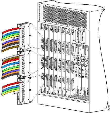
Figure 1 shows the Cisco uBR10012 universal broadband router with the Cisco uBR10-MC5X20S/U/H cable interface line cards installed.
Figure 1 Cisco uBR10012 Chassis with Cisco uBR10-MC5X20S/U/H Cards
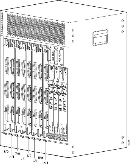
Figure 2 shows the faceplate of the Cisco uBR10-MC5X20S/U/H cable interface line card.
Figure 2 Cisco uBR10-MC5X20S/U/H Cable Interface Line Card with a Dense Connector Configuration
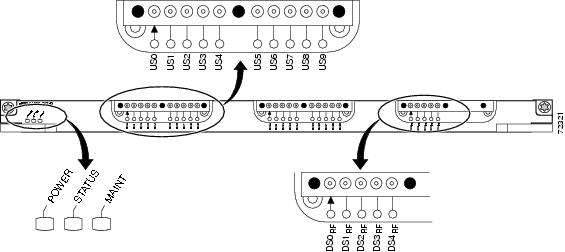
Table 2 describes the LEDs on the Cisco uBR10-MC5X20S/U/H dense connector cable interface line card.
Table 2 Cisco uBR10-MC5X20S/U/H Card LEDs
POWER
Green
Off
Card is powered on.
Card is not powered on.
STATUS
Green
Blinking Green
Yellow
Off
Processor has booted and passed diagnostics.
Protect mode when the card is the redundant card in the system.
In bootup mode.
No power to the line card. See the "Troubleshooting the Cisco uBR10-MC5X20S/U/H Cable Interface Line Card Installation" section.
MAINT
Yellow
Off
It is safe to remove the line card.
No action necessary.
US0 through US19
Green
Off
Upstream-enabled path is configured and able to pass traffic.
Upstream port is not enabled.
DS0 through DS4
Green
Off
RF-enabled downstream path is configured and able to pass traffic out through the upconverter at radio frequencies.
RF is not enabled.
Note
Benefits
The Cisco uBR10-MC5X20S/U/H cable interface line cards provide the following benefits:
•
•
•
•
•
•
•
Onboard Failure Logging
The On-Board Failure Logging (OBFL) feature enables storage and collection of critical failure information in the nonvolatile memory of an Field Replaceable Unit (FRU), like a Route Processor (RP) or line card. The Cisco uBR10000 series router supports OBFL on PRE4, the Cisco SIP-600 jacket card, Cisco UBR-MC20x20V cable line card and the Cisco UBR-MC5x20H cable line card.
The OBFL stored data assists in understanding and debugging field failures upon Return Material Authorization (RMA) of a RP or line card at repair and failure analysis sites.
OBFL records operating temperatures, voltages, hardware uptime and any other important events that assist board diagnosis in case of hardware failures.
For more information on the feature, see the Onboard Failure Logging feature guide located at the following URL:
http://www.cisco.com/en/US/docs/ios/12_2sx/12_2sxh/feature/guide/sxhobfl.html#wp1053048

Note
Logging details for OBFL
The logging details for the OBFL feature are described below:
•
•
•
•
•
•
•
•
Storing OBFL Data
OBFL logs are recorded in the bootflash device on the Cisco UBR-MC5x20H line card. The logs are maintained in a separate 2MB partition, distinct from the Bootflash filesystem partition where the crash dumps are stored. OBFL log files are not accessible to the operator and their contents can be viewed only by using the OBFL CLI commands.
Displaying OBFL Data
The show logging onboard command displays the logs from the OBFL data.
For information on OBFL commands, see the "Configuration Tasks" chapter in the Onboard Failure Logging feature guide located at the following URL:
http://www.cisco.com/en/US/docs/ios/12_0s/feature/guide/12sobfl.html#wp1025118
Safety Information and Warnings
Following are safety guidelines that you should follow when working with any equipment that connects to electrical power.

Tip
Warning Definition
WarningElectrical Equipment Guidelines
Follow these basic guidelines when working with any electrical equipment:
•
•
•
•
•
•
Preventing Electrostatic Discharge Damage
Electrostatic discharge (ESD) damage, which occurs when electronic cards or components are improperly handled, can result in complete or intermittent failures. The AC-input power shelf and its AC power modules contain a printed circuit card that is fixed in a metal carrier. Electromagnetic interference (EMI) shielding and connectors are integral components of the carrier. Although the metal carrier helps to protect the cards from ESD, use an anti-static strap each time you handle the modules.
Following are guidelines for preventing ESD damage:
•
•
•
•

Caution
Installing and Replacing a Cisco uBR10-MC5X20S/U/H Cable Interface Line Card
Note
Note
Caution
Tools and Equipment
•
Replacement Cisco uBR10-MC5X20U card: UBR10-MC5X20U=
Replacement Cisco uBR10-MC5X20H card: UBR10-MC5X20H=
Blank uBR10012 card (if required): UBR10-MC-COVER=•
•
•
Unpacking the Cisco uBR10-MC5X20S/U/H Cable Interface Line Card
To unpack the Cisco uBR10-MC5X20S/U/H cable interface line card, complete the following steps:
Caution
Step 1
Step 2
Step 3
Step 4
Installing the Cisco uBR10-MC5X20S/U/H Cable Interface Line Card in the Card Slot
Caution
Step 1
Caution
When installing cards for the first time, or when all the card's captive screws are loose, insert cards first in slot 5/1 and work towards slot 8/0 to prevent uneven gasket pressure.
Step 2
Figure 3 Inserting the Cisco uBR10-MC5X20S/U/H Cable Interface Line Card
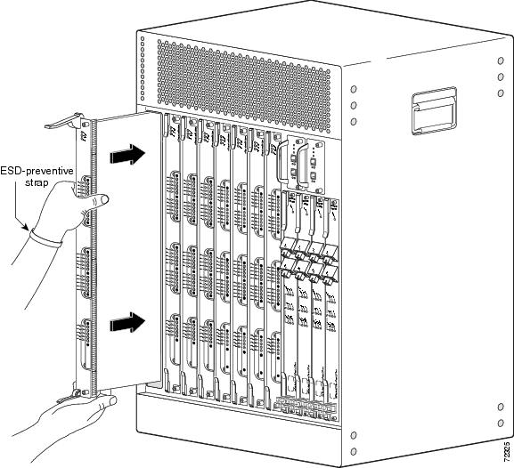
Figure 4 Closing the Ejector Levers
Step 3
Step 4
Caution
Step 5
Removing the Cisco uBR10-MC5X20S/U/H Cable Interface Line Card from the Card Slot
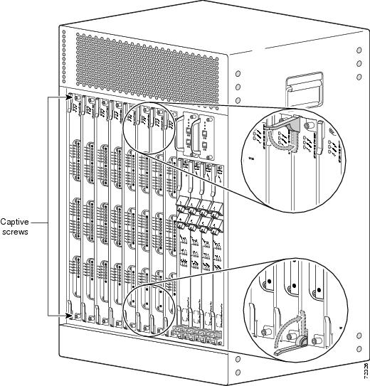
Step 1
Step 2
Figure 5 Unscrewing the Captive Screws and Opening the Ejector Levels
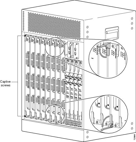
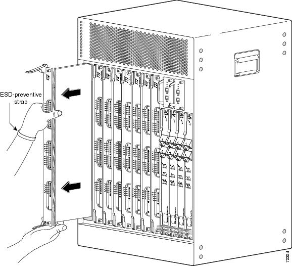
Figure 6 Removing the Cable Interface Line Card from the Chassis
Caution
Step 3
Step 4
Caution
Replacing the SODIMM on the Cisco uBR10-MC5x20H Line Card
Caution
For information on replacing the SODIMM, see Replacement of SODIMM on the Cisco uBR10-MC5X20H Line Card.
Using the Universal Cable Holder on Cisco uBR10-MC5X20 Line Cards
The Cisco uBR10-MC5X20S/U/H cable interface line card must be used with the provided UCH for all cable connections to the line card. Failure to use the UCH may cause permanent damage to the line card connectors, resulting in low or no RF output in the downstream or low or no RF input in the upstream.
Perform the following procedures to install or replace, and remove UCH on the Cisco uBR10-MC5X20 line cards:
•
•
Both the UCH1 and UCH2 universal cable holders can be used with the Cisco UBR10-MC5X20S/U/H cable interface line cards. Both UCHs are designed to stabilize the cables and hold them in place.
Depending on your UCH, refer to the following sections:
•
•
Note
http://www.cisco.com/en/US/docs/interfaces_modules/cable/broadband_processing_engines/ubr10_mc5x20s_u_h/quick/start/520QSC02.html
The dense connector configuration comes with the following equipment:
•
•
•
•
Note
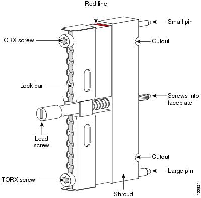
Figure 7 shows the UCH1. Figure 8 shows the UCH2. The UCH is used to group, hold, and protect the MCX cables when they are installed on the Cisco uBR10-MC5X20S/U/H cable interface line card. Always use the UCH when cabling the Cisco uBR10-MC5X20S/U/H card.
Figure 7 Universal Cable Holder (UCH): UCH1
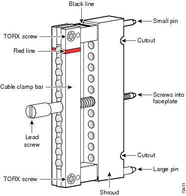
Figure 8 Universal Cable Holder (UCH): UCH2
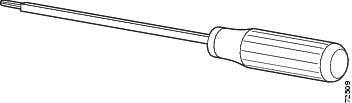
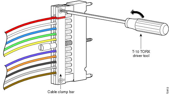
The T-10 TORX driver tool (see Figure 9) and a 1/4-inch flathead screwdriver are used to remove and install the cable bar clamp on the UCH, and loosen the line card captive screws.
Figure 9 T-10 TORX Driver Tool
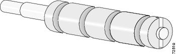
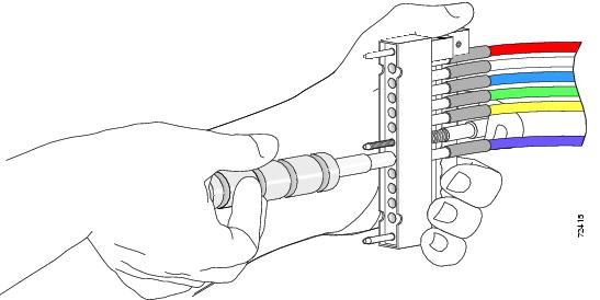
The cable extractor tool (see Figure 10) is used to remove the cables from the UCH1 only. It is not used with the UCH2.
Figure 10 Cable Extraction Tool
The Cisco uBR10-MC5X20S/U/H cable interface line card uses bundled cables. The cables come in bundles of 5 cables or 10 cables. Figure 14 shows a MC5X20 dual-shielded cable bundle with 10 cables. This particular dual-shielded cable configuration can be used when you are cabling the Cisco uBR10-MC5X20S/U/H card directly to the cable plant.
Note
The Cisco uBR10-MC5X20S and U can use dual-shielded or quad-shielded cables in all regions.
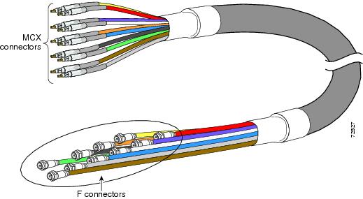
Figure 11 shows the cable bundle for RF card to HFC plant that has three UCH2 units attached to one end and 25 F connectors attached to the other end. This cable is 9.84 feet (3 m) long and the part number is CAB-RFSW520QTIMF2.
Figure 11 Cable Bundle with UCH2 Units and F Connectors
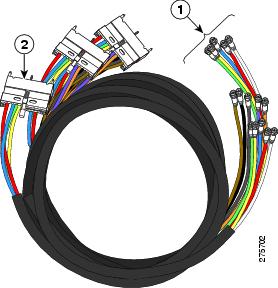
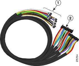
Figure 12 shows the cable bundle for RF card to RF switch that has three UCH2 units attached to one end and two RF switch header blocks attached to the other end. This cable is 3.2 feet (1 m) long and the part number is CAB-RFSW520QTIMM2.
Figure 12 Cable Bundle with UCH2 Units and RF Switch Header Blocks
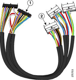
Figure 13 shows the cable bundle for RF switch to HFC plant that has two RF switch header blocks attached to one end and 25 F connectors attached to the other end. This cable is 9.84 feet (3 m) long and the part number is CAB-RFSW520QTPMF2.
Figure 13 Cable Bundle with RF Switch Header Blocks and F Connectors
Note
If you are cabling the card to the Cisco uBR 3X10 RF Switch, you must have MCX connectors at either end of the cable.
Figure 14 10-Bundle Dual-Shielded Cable with MCX Connectors
Note
Installing the UCH on the Cisco uBR10-MC5X20S/U/H Card
Note
Caution
For the UCH1 only, the cables must be installed before you install the UCH1 into the card. Do not attempt to install or remove cables in the cable UCH1 while it is attached to the cable interface line card. For more information, see the "Installing or Replacing Cables in the UCH1" section.
To install the UCH, complete the following steps:
Step 1
For a UCH2, position the UCH so the red line is on the same side as the red triangle on the card.
Step 2
Caution
Step 3
Step 4
Caution
Note
For a UCH2, as you turn the leadscrew clockwise, the outer shroud on the UCH moves to cover the red line on the top and the black line on the bottom of the UCH. The half circles on the edge of the shroud appear to close as the shroud fits down over the UCH. Full engagement is indicated by visible metal-to-metal contact between the UCH and the faceplate (check the half circle cutouts).
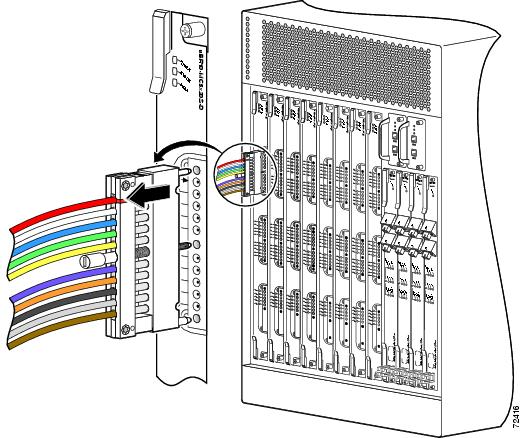
Figure 15 Aligning the UCH with the Cable Interface Card Dense Connector Ports
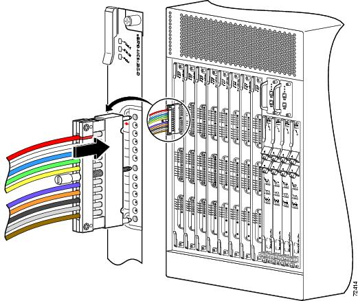
Figure 16 Installing the UCH on the Faceplate
Step 5
Step 6
Note
Removing the UCH from the Cisco uBR10-MC5X20S/U/H Cable Interface Line Card
Note
Figure 17 and Figure 18 show the UCH1 being removed from the cable line card. The removal process is the same for the UCH2.
Caution
Step 1
Step 2
Step 3
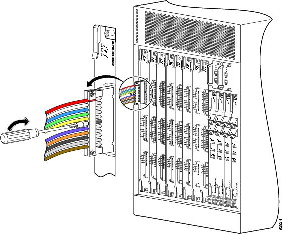
Figure 17 Unscrewing the UCH

Step 4
Caution
Figure 18 Removing the UCH from the Line Card
Step 5
Step 6
Installing or Replacing Cables in the UCH1
Tools and Equipment
The tools listed below are designed to help you remove and install cables in the UCH1.
•
•
•
Note
•
Removing Cables
To remove the old cables, complete the following steps:
Step 1
Step 2
Caution
Figure 19 Using the T-10 TORX Driver Tool to Remove the UCH1 Clamp Bar
Step 3
Caution
Figure 20 Using the Cable Ejector Tool on the UCH1
Step 4
Step 5
Note
Step 6
Step 7
Install Cables
Cisco cables are color-coded for easy reference and installation. The cable color corresponds to a specific port on the card. The tables include a column for users to define ports and color definitions.
See Table 3 for a list of the cable ports and associated cable color applicable when using MC5X20 dual/qual-shielded cables.
See Table 4 for a list of the cable ports and associated cable color applicable when using MC5X20 legacy 5-color quad-shielded cables.
Note
The Cisco uBR10-MC5X20S and U can use dual-shielded or quad-shielded cables in all regions.
Note
Table 3 MC5X20 Dual/Qual Shielded Cable Ports and Cable Colors
User DefinedUS1 0
Red
US10
Grey
DS2 0
Red
US1
White
US11
Brown
DS1
White
US2
Blue
US12
Red
DS2
Blue
US3
Green
US13
White
DS3
Green
US4
Yellow
US14
Blue
DS4
Yellow
US5
Violet
US15
Green
—
—
US6
Orange
US16
Yellow
—
—
US7
Black
US17
Violet
—
—
US8
Grey
US18
Orange
—
—
US9
Brown
US19
Black
—
—
1 US = upstream
2 DS = downstream
Table 4 Legacy 5-Color MC5X20 Quad-Shielded Cable Ports and Cable Colors
User DefinedUS1 0
Red
US10
Red
DS2 0
Red
US1
White
US11
White
DS1
White
US2
Blue
US12
Blue
DS2
Blue
US3
Green
US13
Green
DS3
Green
US4
Yellow
US14
Yellow
DS4
Yellow
US5
Red
US15
Red
—
—
US6
White
US16
White
—
—
US7
Blue
US17
Blue
—
—
US8
Green
US18
Green
—
—
US9
Yellow
US19
Yellow
—
—
1 US = upstream
2 DS = downstream
Figure 21 Cable Locations and Cable Colors
To replace cables or install new cables in a UCH1, complete the following steps:
Step 1
Step 2
Caution
Step 3
Step 4
Step 5
Caution
Step 6
Note
Figure 22 Removing an ESD Cap from a MCX connector
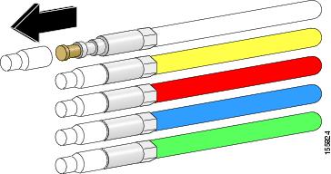
Figure 23 Removing an ESD Cap from an F connector
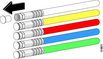
Figure 24 Placing Cables in the UCH1
Installing or Replacing Cables in the UCH2
Tools and Equipment
The tools listed below are designed to help you remove and install cables in the UCH2.
•
•
Note
•
Removing Cables
To remove the old cables, complete the following steps:
Step 1
Step 2
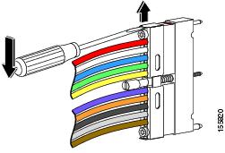
Figure 25 Using the T-10 TORX Driver Tool to Loosen the UCH2 Lock Bar
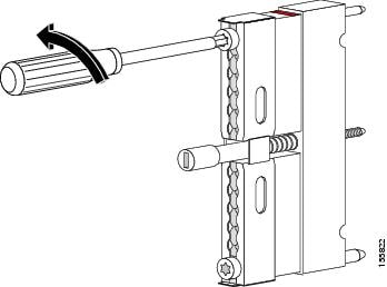
Figure 26 Using a Screwdriver to Slide Open the Lock Bar on the UCH2
Step 3
Caution
Note
Step 4
Installing Cables
Cisco cables are color-coded for easy reference and installation. The cable color corresponds to a specific port on the card. The tables include a column for users to define ports and color definitions.
See Table 3 for a list of the cable ports and associated cable color applicable when using MC5X20 dual-shielded cables or quad-shielded cabling.
Note
Precision miniature video coaxial cables come in various colors, and you can use any cable color combination. However, when you are connecting the Cisco uBR10-MC5X20S/U/H cable interface card to the Cisco RF switch, we recommend that you install the cables in the UCH as shown in Figure 21, and listed in Table 3.
To replace cables or install new cables in a UCH2, complete the following steps:
Step 1
Step 2
Step 3
Step 4
Note
Step 5
Note
Step 6
Note
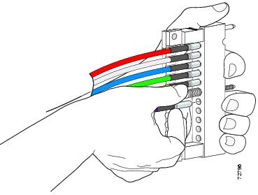
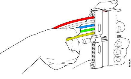
Figure 27 Placing Cables in the UCH2
Adding Heat-Shrink Tubing to Custom Built Cables
Note
The heat-shrink tubing adds rigidity to the connection between the connector and the cable. The tubing is not required, but recommended. This procedure describes how to add heat-shrink tubing to the cables.
Tools and Equipment
•
•
•
•
•
•
Note
Adding Heat-Shrink Tubing
To add heat-shrink tubing to the cable, complete the following steps:
Step 1
Step 2
Step 3
Note
Step 4
Figure 28 Heat-Shrink Tubing on Cable Before Shrinking
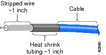
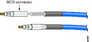
Figure 29 Install a MCX connector per manufacturers instructions.
Figure 30 Installing MCX Connectors
Step 5
Step 6
Step 7
Note
Troubleshooting the Cisco uBR10-MC5X20S/U/H Cable Interface Line Card Installation
Check the following:
1.
a.
b.
2.
a.
b.
c.
3.
a.
Note
(1.69 Nm).
4.
a.
b.
c.
Note
5.
Downstream RF Power Measurement Caution
Caution
If downstream RF power measurements are made to this line card, all the ESD precautions listed below must be followed to prevent damage to the product:
1.
2.
3.
4.
Broken Leadscrews
To remove a lead screw that has broken off in the faceplate of the card, complete the following steps:
Step 1
a.
b.
Note
Step 2
Step 3
Step 4
Step 5
Technical Specifications and Component Part Numbers
The following tables provide specification information for the Cisco uBR10-MC5X20S/U/H cable interface line cards.
Physical Specifications and Compliance Information
Table 5 lists the physical specifications for the Cisco uBR10-MC5X20S/U/H cable interface line cards.
Table 5 Cisco uBR10-MC5X20S/U/H Cable Interface Line Card Specifications
Card dimensions
•
•
•
Weight
16 lb (7.26 kg)
Cisco uBR10-MC5X20S
Cisco uBR10-MC5X20U
Cisco uBR10-MC5X20H185W1 (631.2 BTU/hr2 )
175W (597.1 BTU/hr)
185W (631.2 BTU/hr)Cisco uBR10-MC5X20S
Cisco uBR10-MC5X20U
Cisco uBR10-MC5X20H185W (631.2 BTU/hr)
175W (597.1 BTU/hr)
185W (631.2 BTU/hr)Cisco uBR10-MC5X20S
Cisco uBR10-MC5X20U
Cisco uBR10-MC5X20H28,153 hours
41,089 hours
43,957 hoursTemperature range
•
•
Relative humidity
•
•
Operating altitude
-197 to 13,123 ft. (-60 to 4000 m)
Cisco uBR10-MC5X20S
Cisco uBR10-MC5X20U
Cisco uBR10-MC5X20H
DOCSIS ITU J.112, ITU J.83 Annex B
DOCSIS ITU J.112, ITU J.83 Annex A, Annex B
DOCSIS 1.1
DOCSIS MAC management
DOCSIS spectrum management
CableLabs ECR; RFI-R-98036
DOCSIS 2.0 A-TDMA supportCisco uBR10-MC5X20S
Cisco uBR10-MC5X20U
Cisco uBR10-MC5X20HCisco IOS Release 12.2(11)BC2 or later release
Cisco IOS Release 12.2(15)CZ or later release
Cisco IOS Release 12.3(17a)BC4 or later release
1 W = Watts
2 BTU/hr = British thermal units per hour
RF Specifications
Input
Table 6 shows DOCSIS 1.0 input specifications.
Table 6 DOCSIS 1.0 Supported Upstream Modulation Schemes (US0—US19)
0.2
—
0.16
0.32
0.64
0.23
0.55
-16 to +14
0.4
—
0.32
0.64
1.28
0.55
1.1
-13 to +17
0.8
—
0.64
1.28
2.56
1.1
2.2
-10 to +20
1.6
—
1.28
2.56
5.12
2.2
4.4
-7 to +23
3.2
—
2.56
5.12
10.24
4.4
8.8
-4 to +26
1 The DOCSIS specifications state that each channel width has a range that it can work within.
Table 7 shows DOCSIS 2.0 input specifications.
Table 7 DOCSIS 2.0 Supported Upstream Modulation Schemes (US0—US19)
6.4
5.12
10.12
20.48
30.72
8.8
17.6
26.4
-1 to +29
1 The DOCSIS specifications state that each channel width has a range that it can work within.
Output
Table 8 shows output specifications.
Noise
Figure 30 shows noise specifications.
RF Specifications Specific to Cisco uBR-MC5X20U and H
The following specifications are specific to the Cisco uBR-MC5X20U and H cable interface line cards with onboard upconverters.
Part Numbers
Table 11 lists the part numbers for the Cisco uBR10-MC5X20S/U/H cable interface line cards, cable kits, cables, connectors, tubing, and tools.
Table 11 Part Numbers
1.
2.
3.
4.
1.
2.
3.
4.
1.
2.
3.
1.
2.
3.
1.
2.
1.
2.
RF Switch header blocks for MCX connectors, qty 4 pcs
CAB-RFSW-MULT-HB
Cable extraction tool (for the UCH1 only)
REMTOOL, White Sands Engineering
1.
2.
1.
2.
1.
2.
3.
1.
2.
3.
1.
2.
1.
2.
MCX connector to F connector adapter
PN-53140137, White Sands Engineering
F connector strip tool
1.
2.
1.
2.
MCX and F connector crimper tool
PN-ACT- 483, White Sands Engineering
1.
2.
1.
2.
Shrink tubing
Size: 1/4 inch
Shrink ratio: 2:1
Recovered wall thickness: 0.025 inch
Inside diameter after recovery: 0.125 inchNote
—
1 Johnson Components at the following URL: http://www.johnsoncomponents.com/
2 White Sands Engineering at the following URL: http://www.whitesandsengineering.com/
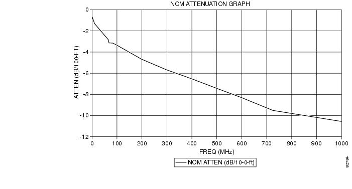
Nominal Attenuation
Table 12 shows the nominal attenuation for specified cable lengths.
Figure 31 Nominal Attenuation Graph for 75-Ohm Miniature Headend Coaxial Cable
Related Documentation
For more information about the Cisco uBR10-MC5X20S/U/H cable interface line cards, Cisco uBR10012 router chassis, and software configuration, see the following documents:
•
•
•
•
•
http://www.cisco.com/en/US/products/hw/cable/ps2929/prod_installation_guides_list.html
•
http://www.cisco.com/en/US/docs/cable/cmts/ubr10012/installation/guide/hig.html
•
http://www.cisco.com/en/US/products/hw/cable/ps2209/prod_release_notes_list.html
•
http://www.cisco.com/en/US/products/hw/cable/ps2209/products_feature_guides_list.html
•
http://www.cisco.com/en/US/docs/cable/cmts/ubr10012/configuration/guide/scg.html
•
http://www.cisco.com/web/techdoc/cable/Config/Sw_conf.html
•
http://www.cisco.com/en/US/docs/ios/cable/command/reference/cbl_book.html
Obtaining Documentation and Submitting a Service Request
For information on obtaining documentation, submitting a service request, and gathering additional information, see the monthly What's New in Cisco Product Documentation, which also lists all new and revised Cisco technical documentation, at:
http://www.cisco.com/en/US/docs/general/whatsnew/whatsnew.html
Subscribe to the What's New in Cisco Product Documentation as a Really Simple Syndication (RSS) feed and set content to be delivered directly to your desktop using a reader application. The RSS feeds are a free service and Cisco currently supports RSS version 2.0
Cisco and the Cisco logo are trademarks or registered trademarks of Cisco and/or its affiliates in the U.S. and other countries. To view a list of Cisco trademarks, go to this URL: www.cisco.com/go/trademarks. Third-party trademarks mentioned are the property of their respective owners. The use of the word partner does not imply a partnership relationship between Cisco and any other company. (1110R)
Any Internet Protocol (IP) addresses used in this document are not intended to be actual addresses. Any examples, command display output, and figures included in the document are shown for illustrative purposes only. Any use of actual IP addresses in illustrative content is unintentional and coincidental.
© 2009, 2012 Cisco Systems, Inc. All rights reserved.

 Feedback
Contact Cisco
- Open a Support Case

- (Requires a Cisco Service Contract)