Table Of Contents
Cisco Media Gateway Controller Node
Cisco Media Gateway Controller
Cisco Signaling Link Terminals
Cisco Catalyst 5500 Multiswitch Routers
Cisco MGC Software Architecture
Execution Environment Process Shell
Cisco MGC Software Directory Structure
Cisco MGC System Overview
This chapter provides an overview of the components of the Cisco Media Gateway Controller (MGC) node, and of the software architecture of the Cisco MGC software Release 7, which is used in both the Cisco SC2200 Signaling Controller and the Cisco PGW 2200 products.
![]()
Note
The Cisco PGW 2200 was formerly known as the Cisco VSC3000 Virtual Switch Controller. Some parts of this document may use this older name.
This information is described in the following sections:
•
Cisco Media Gateway Controller Node
•
Cisco MGC Software Architecture
•
Cisco MGC Software Directory Structure
Cisco Media Gateway Controller Node
The following subsections briefly describe the components of the Cisco MGC node:
•
Cisco Media Gateway Controller
•
Cisco Signaling Link Terminals
•
Cisco Catalyst 5500 Multiswitch Routers
The Cisco MGC Node Manager (CMNM) and Billing and Measurements Server (BAMS) are optional components of the Cisco MGC node that are not dealt with in this document. For more information on the CMNM, refer to the Cisco Media Gateway Controller Node Manager User's Guide. For more information on the BAMS, refer to the Billing and Measurements Server User's Guide.
Cisco Media Gateway Controller
The Cisco MGC is a Sun Netra UNIX host running Cisco MGC software Release 7. The Cisco MGC performs real-time call-processing and SS7 layer functions; manages trunk resources, alarms, and call routing; and administers billing information.
Cisco MGC functionality includes:
•
Processing calls
•
Originating call detail records (CDRs)
•
Providing alarm initiation information
•
Producing operational peg counts
•
Receiving and processing craft user interface (CUI) data
•
Providing Message Transfer Part (MTP) Level 3 (MTP3) functions
•
Providing advanced intelligent network (AIN) capabilities
Sun Netra Hosts
Sun Netra UNIX hosts serve as the platform for the Cisco MGC software Release 7. The Sun Netra hosts meet or exceed Network Equipment Building System (NEBS) Level 3 standards.
Using two Sun Netra UNIX hosts in a continuous service configuration provides system redundancy and reliability. The call-processing application is active on one Cisco MGC and switches to the standby Cisco MGC only under failure conditions.
Cisco Signaling Link Terminals
The Cisco Signaling Link Terminals (SLTs) terminate SS7 links. Each Cisco SLT supports up to two signaling network connections. Multiple Cisco SLTs (up to 16 per Cisco MGC node) can be used to support additional signaling channels or provide redundant signal paths between the signaling network and the control signaling network. The Cisco SLTs support V.35, T1 and E1 interfaces to the SS7 network. Each interface card supports a single DS0 signaling channel. MTP Level 1 (MTP1) and MTP Level 2 (MTP2) are terminated at the Cisco SLTs and the remaining SS7/C7 layers are backhauled, using the Reliable User Datagram Protocol (RUDP), over a 10BASE-T Ethernet interface across the IP network to the Cisco MGC host.
Cisco Catalyst 5500 Multiswitch Routers
The Cisco Catalyst 5500 multiswitch routers are local area network (LAN) switches that are used to create the Ethernet backbone between the Cisco MGCs, Cisco SLTs, and Cisco media gateways. The Cisco Catalyst 5500 is the recommended LAN switch for the Cisco MGC node.
Ethernet Connections
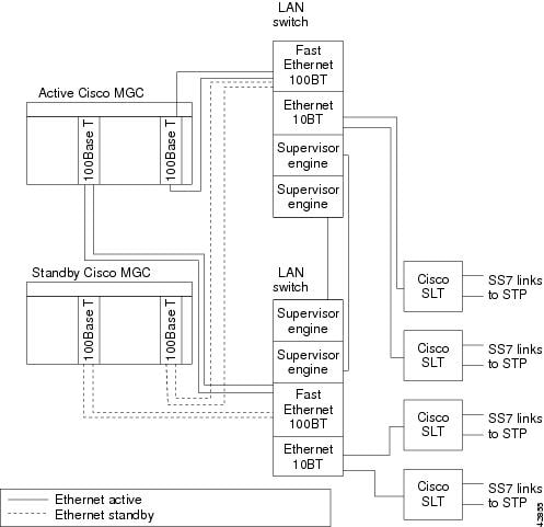
Each Ethernet NIC for each Cisco MGC is connected by a 100BASE-T interface to the LAN switches. The LAN switches connect to the Cisco SLTs using 10BASE-T interfaces. Figure 1-1 displays the Ethernet connections between the elements of the Cisco MGC node.
Figure 1-1 Cisco MGC Node Connectivity
![]()
Cisco MGC Software Architecture
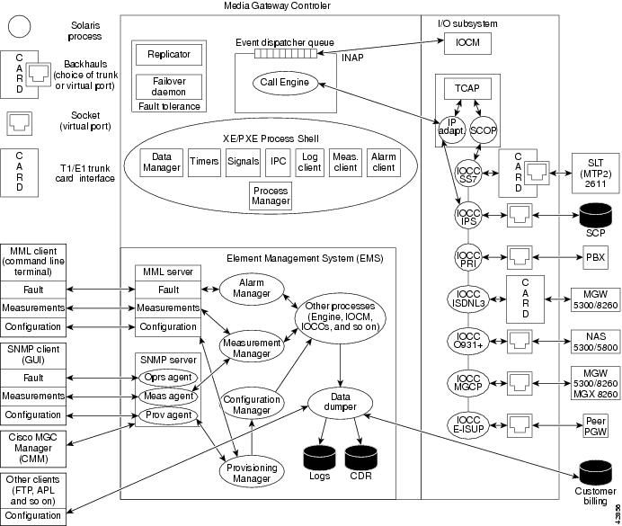
This section describes the major subsystems in the Cisco MGC software, which are illustrated in Figure 1-2. The major subsystems are
•
Execution Environment Process Shell
Figure 1-2 Cisco MGC Software System Diagram
![]()
Input/Output Subsystem
The Input/Output (I/O) subsystem consists of the I/O channel controllers (IOCC) and the I/O channel manager (IOCM), which manages them.
•
The IOCM manages all IOCCs and keeps the hardware resource states of the hardware controlled by the IOCCs.
•
The IOCCs provide
–
A protocol-specific, message-based interface that allows nodes and platforms external to the Cisco MGC to communicate with the Cisco MGC.
–
An interface that allows buffering of messages to the call engine's event dispatcher queue.
•
The Cisco MGC I/O subsystem includes the following IOCCs:
–
Internet protocol services (IPS)—Designed to migrate Transaction Capabilities Application Part (TCAP) on top of TCP/IP for connecting to Signal Transfer Points (STPs) and Service Control Points (SCPs) for intelligent network (IN) services.
–
Signaling System 7 (SS7)—Contains MTP3 used for backhauling SS7 signaling to the
Cisco MGC from a Cisco SLT.–
Primary Rate Interface (PRI)—Supports ISDN termination to a private branch exchange (PBX).
–
ISDN Level 3—Provides backhauling of ISDN (standard variants) to the Cisco MGC from a media gateway.
–
Q931+—Is a stateless IOCC, a special version of ISDN that enables forwardhauling of Q931+ signaling to a media gateway used in Cisco SC2200 environments.
–
Media Gateway Control Protocol (MGCP)—Enables communication to media gateways and trunking gateways for setting up bearer channel connections used in Cisco PGW 2200 environments.
–
Extended ISDN User Part (E-ISUP)—Cisco-proprietary internal interface that enables the transport of endpoint and media gateway specific information between two (or more) Cisco MGCs. This protocol uses an enhanced ISUP base to support all ANSI and ITU ISUP messaging and elements, as well as additional fields to support transport of service information (such as local number portability (LNP), 800 numbers, and so on).
Element Management Subsystem
The Element management subsystem (EMS) allows external client software or terminals to gain access to the data in the Cisco MGC. The functions this subsystem supports are:
•
Configuration management—Adding, deleting, or modifying parameters and resources needed by the Cisco MGC to perform its switching function. This data is stored locally in data (.dat) files. This data is required to automate reconfiguration after a process failure.
•
Alarm management—Reporting and clearing alarms generated by Cisco MGC processes.
•
Performance measurement management—Reporting and clearing metrics generated by
Cisco MGC processes. You can also define thresholds which, if exceeded, could produce alarms.•
Accounting management—Dumping generated call detail records (CDRs) to locally persistent files or to remote databases through a standard or customized API.
The following types of external clients can access or manipulate data on the Cisco MGC:
•
Man-Machine Language (MML) terminal—Serves as a command-line interpreter where a craftsperson can manipulate data for fault detection, measurements, or configuration through a series of commands. MML is similar to TL/1 and is best suited for low-level system experts (such as operations personnel) for rapid system configuration or troubleshooting.
•
SNMP-Based Terminal—Any client using SNMP, usually a craftsperson with a graphical user interface (GUI) application, can access data for fault reporting, measurements, configuration, or security. SNMP applications are best suited for end users and allow development of elaborate multiplatform client applications to satisfy diverse customer needs.
Starting with Release 7.4(11), the Cisco MGC uses a master agent, EMANATE from SNMP Research, and related subagents to enable SNMP access to the system. The Cisco MGC uses the following subagents:
![]()
Note
Refer to the Release Notes for the Cisco Media Gateway Controller Software Release 7.4(11) for more information.
–
Operations—A custom subagent that provides access to fault data
–
Measurement—A custom subagent that provides access to measurement data
–
Critical application monitor—A standard CIAgent subagent that is used to monitor the process manager process
–
Host resources MIB—A standard CIAgent subagent that is used to access data, such as the number of processors, and memory usage on the Cisco MGC host platform
–
MIB-II—A standard CIAgent subagent that partially supports the MIB-II standard (RFC-1213)
–
File system monitor—A standard CIAgent subagent that monitors thresholds for five file systems
•
Cisco MGC Manager (CMM)—Is an application used for provisioning the Cisco MGC.
•
Cisco Voice Service Provisioning Tool (VSPT)—As of Release 7.4(11), this application can be used for provisioning the Cisco MGC. Refer to the Release Notes for the Cisco Media Gateway Controller Software Release 7.4(11) for more information.
•
Cisco MGC Node Manager (CMNM)—Is an optional application used for network element (NE) management.
Fault Tolerance Subsystem
The goal of the fault tolerance subsystem is to ensure call preservation if the Cisco MGC encounters a fault condition. There are two processes that ensure this:
•
Failover daemon—Monitors Cisco MGC processes using a heartbeat mechanism. If there is no response to its process polling in a fault-tolerant hardware configuration, the Cisco MGC switches control to the standby unit.
•
Replicator—Allows processes to checkpoint critical call information, such as signaling and bearer states, as well as call data across the active and standby processors. Its goal is to replicate enough information for established calls to survive a failover. Checkpointing events are generated at two points in a call:
–
When the call is answered, to update the full duplex path.
–
When the call is released, after the physical resources are deallocated.
Connectionless (non-call) signaling may be generated by a craftsperson performing maintenance through an MML or SNMP client or by circuit supervision.
Certain signaling can also generate checkpointing events:
–
Blocking or unblocking of circuits
–
Circuit reset
![]()
Note
The replicator mechanism does not try to replicate program or data storage. Service features are not checkpointed across processors; there is just enough information to maintain the voice or data path between the call originator and the call terminator.
If the switchover happens before the simplex path is established, call processing cannot proceed on the inactive side. Non-established calls in the process of being set up are lost.
Execution Environment Process Shell
The execution environment provides an operating system process shell used by Cisco MGC processes to access lower-level functionality. Such functionality holds together the I/O, element management, and call engine subsystems in the Cisco MGC. The execution environment infrastructure provides the following functions to Cisco MGC processes:
•
Operating system interface—Such as the Sun Solaris operating system.
•
Process management—Performs startup order, shutdown order, and monitoring of processes. Also performs software upgrade compatibility checking with minimal service interruption.
•
Alarm management—Allows processes to register, set, and clear alarms, which are then presented to the EMS for further processing.
•
Log management—Allows MGC processes to log messages to locally persistent data files. Message codes (instead of strings) minimize the overhead of interprocess transport of long buffers. Log files use a facility (process type originating the log) and a logging level (severity).
•
Measurement management—Allows processes to adjust counters or other metrics, which are subsequently presented to the EMS for Alarm and Measurement Report processing.
•
Command management—An interface that can be used by any active processes or by an EMS interface, such as MML or SNMP agents, to exchange commands or responses.
•
Configuration management—Notifies processes and gets responses when configuration data changes. Handles reconfiguration management when multiple processes are affected by changes.
•
Access control—Allows only authorized processes to access certain services or other processes.
•
Interprocess communication (IPC)—Allows processes to exchange messages.
•
Event Processing Service—The XEProcShell facility allows applications to register, deregister, and exchange events (messages) through IPC. This service is critical to efficient real-time CPU usage and overall system performance.
•
Timers—Allow processes to set, clear, or monitor timers. Provide timeouts to processes.
Call Engine Process
The call engine is a process designed to provide the means and resources for call processing to take place. The call engine involves the following components:
•
Resource manager—Performs the following functions:
–
Tracks all bearer resources used. Proxies and tracks the bearer resources in the trunking gateways within the Cisco MGC's service area.
–
Services all requests for allocation or deallocation of bearer resources from call instances.
–
Executes bearer allocation algorithms (circuit selection).
–
Manages echo cancellation on the call's behalf.
–
Performs continuity tests.
–
Checkpoints bearer states and modes to the standby Cisco MGC to guarantee that the bearer channel is not lost during a manual or automatic switchover.
•
Connection manager—Interfaces with the nodes and protocols external to the Cisco MGC that are necessary to establish an IP (TCP, UDP, or RUDP) or PSTN connection that is managed by the
Cisco MGC. The type of node supported is–
VoIP/VoATM trunking gateways using MGCP.
–
Time Domain Multiplex (TDM) trunking gateways using MGCP.
•
Call manager—Contains and selects the appropriate protocol adapters. These are protocol-specific entities performing the following functions:
–
Communicates with the corresponding protocol-specific IOCC.
–
Converts incoming protocol data units (PDUs) received from the IOCC to an internal, protocol independent format.
–
Converts internal, protocol-independent PDUs to protocol-specific format.
–
Communicates current circuit states to the IOCM using the IOCCs.
–
Creates a call instance when an incoming MTP3 call establishment message is received.
–
Destroys that instance and frees any associated memory when the call is terminated.
–
Supports multiple call instances. It dequeues incoming messages from the event dispatcher queue and routes them to the call instance for which they are destined.
–
Generates call detail blocks (CDBs), which are used to create CDRs.
–
Operates as a standby entity, which is created when the call engine is created at system startup, and waits to create a new call, destroy an existing call, or process an event for an existing call.
–
Checkpoints call information, such as call signaling state and data, to the standby Cisco MGC to guarantee that the signaling link is not lost during a manual or automatic switchover.
Call Instance Component
A call instance is the dynamic component of the Cisco MGC that is created at run time and is the place where call processing takes place. The call instance is commonly referred to as the Message Definition Language (MDL) component, which is the language used to implement it.
A call is instantiated when an incoming MTP3 call establishment message is received. There is always a one-to-one relationship between a call instance and a call switched by the Cisco MGC.
There are several significant subcomponents involved in a call instance:
•
Originating call control (OCC)—Is the instance of the originating protocol's state machine. In defining a protocol, two MDL modules are created:
–
A general declarations module, which contains protocol-specific types and definitions.
–
A protocol definition module, which contains the state logic for two state machines—one for call origination and one for call termination. This module produces an object file named protocolName.mdo.
•
Universal call model (UCM)—Is a protocol-independent state machine that is used to
–
Provide protocol interworking between the originating and the terminating sides of the call.
–
A UCM MDL module is used to define the UCM behavior and logic. The UCM module is compiled into an object file, but can only be loaded by the Call Engine and cannot be used by any of the protocols.
–
Provide event-driven logic, which controls the following call-processing functions: linking the OCC and the terminating call control (TCC), updating and retrieving the call context structures, interacting with other call engine components, such as the resource manager, connection manager, and call manager, managing bearer resources, such as trunking gateways, using the MGCP, and keeping the call processing state machine.
–
The UCM also triggers events to be processed by the following MDL modules: generic analysis module, subscriber profile retrieval, a-number and b-number pre-analysis, a-number and b-number full analysis, route selection, and the IN trigger module.
•
Connection plane manager (CPM)—Communicates with the call engine's resource manager to make the bearer connections to a remote trunking gateway using MGCP.
•
CDR Manager—Generates CDRs and forwards them to the EMS to be locally persisted or forwarded for off-platform accounting applications. CDRs are generated when calls are answered and they can also be generated in the following situations:
–
End of call (standard)
–
Long duration calls
–
Mid-call CDRs (can generate CDBs at eight different points in a call)
•
Terminating call control—Is the instance of the terminating protocol's state machine.
•
Call context—The following are the call context characteristics:
–
A persistent object in a call instance that serves as the placeholder for bearer and signaling information. Such information is set and retrieved by the OCC, TCC, or UCM at various points in the life of the call.
–
An MDL context definition module is used to define the information elements, structures, and fields. This module is compiled into an object file to be used by all protocols.
The format of these structures is protocol-independent to minimize cross-protocol conversion permutations. Contains rules for data conversion to and from each protocol.
–
Collects the following call information in CDBs, which are assembled to build CDRs: calling number, called number, answer time, disconnect time, originating trunk group and circuit identification code (CIC), terminating trunk group and CIC, address translation and route information, ISUP information, ISDN service information, database query information, call completion codes, and other information depending on the type of call.
Cisco MGC Software Directory Structure
This section shows an overview of the UNIX file directory tree for the Cisco MGC distribution, along with a brief description of the purpose for each directory. This section is to be used as a guide to finding files called out in the operational procedures.
In the installation procedures, the installer is asked for a directory under which to install the Cisco MGC software. The default directory is /opt/CiscoMGC; however, this directory name is installer-definable, so do not assume that /opt/CiscoMGC is always used. This is the directory under which all files for the Cisco MGC reside. The sole exception is some temporary files that are created at run time.
Table 1-1 utilizes the variable $BASEDIR to indicate the directory into which the Cisco MGC software was installed.
Table 1-1 Cisco MGC Software Directory Structure
Directory Description$BASEDIR/bin
Cisco MGC executable programs that cannot be customized.
$BASEDIR/local
Cisco MGC executable programs that can be modified by the customer for a site-specific reason. See the procedures for how to customize files. Generally the factory default values are sufficient.
$BASEDIR/etc
Network element configuration files. This includes all provisionable configuration files required for proper operation of the Cisco MGC.
$BASEDIR/etc/CONFIG_LIB
Cisco MGC configuration file library. This is a simple version control system for configuration file changes.
$BASEDIR/etc/cust_specific/
toolkitSaved data from the Cisco MGC Toolkit applications is stored in this directory.
$BASEDIR/lib
Shared object files. These libraries are loaded at runtime by the executables. The three types of libraries are: (1) system/program shared objects, (2) MDL interpreted objects, and (3) MDL shared objects.
$BASEDIR/var
Subsystem communication and persistent storage area. This directory contains files and devices providing communications between the various subsystems in the Cisco MGC. It also contains files providing persistent storage of data for the Cisco MGC.
$BASEDIR/var/log
System logging area. This directory contains the platform logs. See the "Recovering from a Switchover Failure" section for more information.
$BASEDIR/var/spool
Dumper Spool Area. This directory contains historic reports. See "Configuring Cisco MGC Report Files."
$BASEDIR/var/trace
Signal Path Trace area. This directory contains all MDL trace logs used for conversion analysis.
$BASEDIR/data
MDL source files. MDL source files are generally not provided, but if they are purchased, they will appear here.