ASR1K中通過VRF感知的L2TPv3的Xconnect

下載選項
無偏見用語
本產品的文件集力求使用無偏見用語。針對本文件集的目的,無偏見係定義為未根據年齡、身心障礙、性別、種族身分、民族身分、性別傾向、社會經濟地位及交織性表示歧視的用語。由於本產品軟體使用者介面中硬式編碼的語言、根據 RFP 文件使用的語言,或引用第三方產品的語言,因此本文件中可能會出現例外狀況。深入瞭解思科如何使用包容性用語。
關於此翻譯
思科已使用電腦和人工技術翻譯本文件,讓全世界的使用者能夠以自己的語言理解支援內容。請注意,即使是最佳機器翻譯,也不如專業譯者翻譯的內容準確。Cisco Systems, Inc. 對這些翻譯的準確度概不負責,並建議一律查看原始英文文件(提供連結)。
簡介
本檔案介紹設定第2層通道通訊協定(L2TP)v3 Xconnect over IP和多重通訊協定標籤交換(MPLS)網路時,如何使用虛擬路由和轉送(VRF)。
背景資訊
L2TP是網際網路服務提供商(ISP)使用的通道通訊協定,用於在網際網路上的撥號存取空間中提供虛擬私人網路(VPN)。
它融合了思科的第2層轉送(L2F)協定和Microsoft的點對點隧道協定(PPTP)的優勢。 L2TP的主要元件是L2TP訪問控制器(LAC)和L2TP網路伺服器(LNS)。
L2TP訪問控制器:LAC是接入伺服器,連線到公共交換電話網(PSTN)。LAC是呼入呼叫的發起方和撥出呼叫的接收方。它通過LAN或WAN連線到LNS。
L2TP網路伺服器:LNS是L2TP協定的網路伺服器,在該協定中,PPP會話終止並經過身份驗證。LNS是傳出呼叫的發起者和傳入呼叫的接收者。
L2TPv2旨在通過IP網路傳輸PPP流量。網路接入裝置(DSL、電纜數據機或撥號接入介面)接受來自使用者的PPP連線,並通過L2TP將PPP會話隧道化到ISP。新版本L2TPv3設計為除了版本2支援的唯一負載PPP之外,還承載任何第2層負載。具體來說,L2TPv3定義了在IP核心網路上使用第2層VPN隧道化第2層負載的L2TP協定。此功能的優點包括:
- L2TPv3簡化了VPN的部署
- L2TPv3不需要MPLS
- 對於任何負載,L2TPv3支援通過IP的第2層隧道
以下是L2TPv3偽線的配置示例:
1. enable
2.configure終端
3.interface type slot/port
4.xconnectpeer-ip-address vcidencapsulation l2tpv3pw-classpw-class-name
現在我們來瞭解一下L2TPv3 Xconnect在使用VRF時的行為方式。此處是用來進行演示的拓撲,在該拓撲中,我們在CPE與ASR1002(IP)和ASR1004(MPLS)之間配置了Xconnect,在VRF中ASR1000具有終端(ASR1000平台不支援VRF感知L2TPv3)。
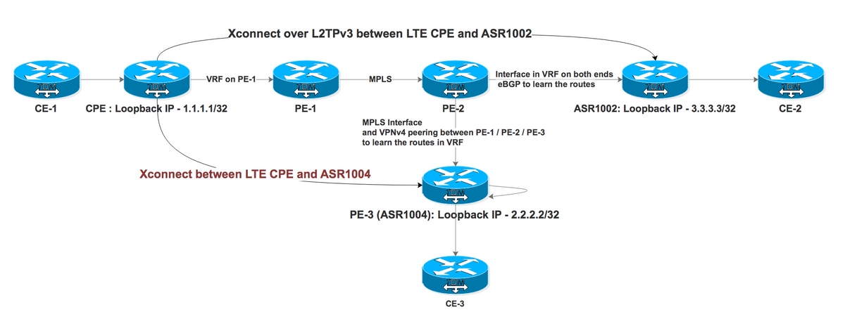
測試案例I:使用VRF中的端點的透過IP網路的L2TPv3 Xconnect

PE-1和PE-2構成了ISP的MPLS網路。CPE通過VRF連線到PE-1,ASR1002通過VRF連線到PE-2。ASR1002在連線到PE-2的介面上也具有VRF。從ASR1002到CPE環回的可達性是通過IP介面的VRF。
CPE上面向ASR1002的Xconnect配置:
interface FastEthernet4.2381

encapsulation dot1Q 2381

xconnect 3.3.3.3 2381 encapsulation l2tpv3 pw-class PSEUDO_CLASS >>>>>>>>>>> Xconnect with ASR1002


pseudowire-class PSEUDO_CLASS

encapsulation l2tpv3

interworking vlan

protocol l2tpv3 L2TP_CLASS

ip local interface Loopback0

ip tos reflect


l2tp-class L2TP_CLASS

authentication

password cisco


interface Gigabit0/1

ip address 192.168.8.190 255.255.255.0

end


Interface Loopback0

ip address 1.1.1.1 255.255.255.255

end


ip route 0.0.0.0 0.0.0.0 192.168.8.1 >>>>>>>>>>>>>> Default route towards PE-1
ASR1002上的工作配置:
interface GigabitEthernet0/0/0.906 —————————————————> Interface connected to PE-2 is in VRF

encapsulation dot1Q 906

ip vrf forwarding L2TP_VRF

ip address 10.1.1.1 255.255.255.252


interface GigabitEthernet0/0/1.2381

encapsulation dot1Q 2381

xconnect 1.1.1.1 2381 encapsulation l2tpv3 pw-class PSEUDO_CLASS


pseudowire-class PSEUDO_CLASS

encapsulation l2tpv3

interworking vlan

protocol l2tpv3 L2TP_CLASS

ip local interface Loopback11


l2tp-class L2TP_CLASS

authentication

password cisco


interface Loopback11

ip vrf forwarding L2TP_VRF ————————————————————————————> Source is in VRF

ip address 3.3.3.3 255.255.255.255


router bgp 1


address-family ipv4 vrf L2TP_VRF

redistribute connected

neighbor 10.1.1.2 remote-as 2 ———————————————> eBGP with PE-2 in VRF

neighbor 10.1.1.2 activate

neighbor 10.1.1.2 soft-reconfiguration inbound

exit-address-family
VRF L2TP_VRF:
B 1.1.1.1/32 [20/0] via 10.1.1.2, 1d ——————————> Xconnect end point learned via eBGP in VRF
現在檢查CPE上Xconnect的狀態:
CPE #sh xconnect all de

Legend:    XC ST=Xconnect State  S1=Segment1 State  S2=Segment2 State

  UP=Up       DN=Down            AD=Admin Down      IA=Inactive

  SB=Standby  HS=Hot Standby     RV=Recovering      NH=No Hardware


XC ST  Segment 1                         S1 Segment 2                         S2

------+---------------------------------+--+---------------------------------+--


UP pri   ac Fa4.2381:2381(Eth VLAN)      UP l2tp 3.3.3.3:2381              DOWN

            Interworking: vlan                   Session ID: 1906980494

                                                 Tunnel ID: 2886222725

                                                Protocol State: DOWN

                                                Remote Circuit State: DOWN

                                                pw-class: PSEUDO_CLASS_VLAN
表示網段2已關閉,這意味著從CPE到ASR1002的路徑出現問題。但是,我們可以對終端執行ping。CPE上的調試顯示到終端的隧道失敗或沒有到終端的路由。
*Feb 15 08:12:47.225: L2TP _____:18136:8DF92CB9/uid:0[1.1.1.1/2381]: I CDN, flg TLS, ver 3, len 80

*Feb 15 08:12:47.225: L2TP _____:18136:8DF92CB9/uid:0[1.1.1.1/2381]:IETF v2:

*Feb 15 08:12:47.225: L2TP _____:18136:8DF92CB9/uid:0[1.1.1.1/2381]:Result Code

*Feb 15 08:12:47.225: L2TP _____:18136:8DF92CB9/uid:0[1.1.1.1/2381]:   Call disconnected for administrative reasons(3)

*Feb 15 08:12:47.225: L2TP _____:18136:8DF92CB9/uid:0[1.1.1.1/2381]:   Error code

*Feb 15 08:12:47.225: L2TP _____:18136:8DF92CB9/uid:0[1.1.1.1/2381]:     No error(0)

*Feb 15 08:12:47.225: L2TP _____:18136:8DF92CB9/uid:0[1.1.1.1/2381]:   Optional msg

*Feb 15 08:12:47.225: L2TP _____:18136:8DF92CB9/uid:0[1.1.1.1/2381]:       "Tunnel failed to 3.3.3.3" >>>>>>>>>>>>>>>>>

*Feb 15 08:12:47.225: L2TP _____:18136:8DF92CB9/uid:0[1.1.1.1/2381]:Cisco v3:
這裡的主要問題是,終端可以通過ASR1002上的VRF訪問。Xconnect終端需要在全域性路由表中才能啟動。現在,讓我們為指向介面GigabitEthernet0/0/0.906(自身在VRF中)的全域性中的CPE Loopback 1.1.1.1/32配置路由。
 ip route 1.1.1.1 255.255.255.255 GigabitEthernet0/0/0.906 10.1.1.2


              S        1.1.1.1/32 [1/0] via 10.1.1.2, GigabitEthernet0/0/0.906
配置完虛擬靜態路由後,Xconnect便會啟動。您還可以將其指向Null0。這是一種解決方法,使路由器相信終端可以通過全域性訪問,而不是VRF,並且只用於控制平面。實際資料平面流量將僅通過VRF。
以下是使用VRF和不使用VRF的ping結果:
ASR1002 #ping 1.1.1.1

Type escape sequence to abort.

Sending 5, 100-byte ICMP Echos to 1.1.1.1, timeout is 2 seconds:

.....

Success rate is 0 percent (0/5)


Ping vrf L2TP_VRF 1.1.1.1

Type escape sequence to abort.

Sending 5, 100-byte ICMP Echos to 1.1.1.1, timeout is 2 seconds:

!!!!!

Success rate is 100 percent (5/5), round-trip min/avg/max = 33/50/72 ms
CPE上的Xconnect狀態:
CPE #sh xconnect all de

Legend:    XC ST=Xconnect State  S1=Segment1 State  S2=Segment2 State

  UP=Up       DN=Down            AD=Admin Down      IA=Inactive

  SB=Standby  HS=Hot Standby     RV=Recovering      NH=No Hardware


XC ST  Segment 1                         S1 Segment 2                         S2

------+---------------------------------+--+---------------------------------+--


UP pri   ac Fa4.2381:2381(Eth VLAN)      UP l2tp3.3.3.3:2381             UP

            Interworking: vlan                   Session ID: 1906980494

                                                 Tunnel ID: 2886222725

                                                Protocol State: UP

                                                Remote Circuit State: UP

                                                pw-class: PSEUDO_CLASS_VLAN
測試案例II:透過MPLS網路進行的L2TPv3 Xconnect,在VRF中具有端點
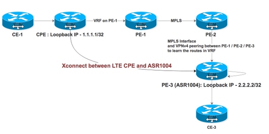
PE-1、PE-2和PE-3使ISP的MPLS網路充當PE-2充當路由反射器(RR)。CPE通過VRF連線到PE-1,ASR1004通過介面上啟用的MPLS連線到PE-2。ASR1004還具有VRF,其中應通過RR從PE-1接收VPNv4路由。ASR1004的CPE looback可達性通過MPLS介面上的VRF實現。
CPE上面向ASR1004的Xconnect配置:
interface FastEthernet4.2380

encapsulation dot1Q 2380

xconnect 2.2.2.2 2380 encapsulation l2tpv3 pw-class PSEUDO_CLASS  >>>>>>>>>>Xconnect with ASR1004


interface FastEthernet4.2381

encapsulation dot1Q 2381

xconnect 3.3.3.3 2381 encapsulation l2tpv3 pw-class PSEUDO_CLASS >>>>>>>>>>> Xconnect with ASR1002


pseudowire-class PSEUDO_CLASS

encapsulation l2tpv3

interworking vlan

protocol l2tpv3 L2TP_CLASS

ip local interface Loopback0

ip tos reflect


l2tp-class L2TP_CLASS

authentication

password cisco


interface Gigabit0/1

ip address 192.168.8.190 255.255.255.0

end


Interface Loopback0

ip address 1.1.1.1 255.255.255.255

end


ip route 0.0.0.0 0.0.0.0 192.168.8.1 >>>>>>>>>>>>>> Default route towards PE-1
ASR1004上的配置:
interface GigabitEthernet0/0/1

no ip address

negotiation auto

service instance 2 ethernet

encapsulation dot1q 2380

xconnect 1.1.1.1 2380 encapsulation l2tpv3 pw-class PSEUDO_CLASS_VLAN

!

end


interface Loopback11

ip vrf forwarding L2TP_VRF —————————————————> Source Loopback in in VRF

ip address 2.2.2.2 255.255.255.255

end


pseudowire-class PSEUDO_CLASS_VLAN

encapsulation l2tpv3

interworking vlan

protocol l2tpv3 L2TP_CLASS

ip local interface Loopback11


l2tp-class L2TP_CLASS

authentication

password cisco


router bgp 2

address-family ipv4 vrf L2TP_VRF

redistribute connected

redistribute static

default-information originate

exit-address-family
Xconnect端點的路由條目:
ASR1004#sh ip rou vrf L2TP_VRF 1.1.1.1 .   ——————————————————> Xconnect End Point also learned via VRF

Routing Table: L2TP_VRF
Routing entry for 1.1.1.1/32
 Known via "bgp 2", distance 200, metric 0, type internal
 Last update from 11.11.11.11 6d17h ago
 Routing Descriptor Blocks:
 * 11.11.11.11 (default), from 22.22.22.22, 6d17h ago
 Route metric is 0, traffic share count is 1
 AS Hops 0
 MPLS label: 18
 MPLS Flags: MPLS Required


We observed that Segment 2 was continuously flapping on both ends.


ASR1004#sh xc all de

Legend:    XC ST=Xconnect State  S1=Segment1 State  S2=Segment2 State

  UP=Up       DN=Down            AD=Admin Down      IA=Inactive

  SB=Standby  HS=Hot Standby     RV=Recovering      NH=No Hardware


XC ST  Segment 1                         S1 Segment 2                         S2

------+---------------------------------+--+---------------------------------+--

DN pri   ac Gi0/0/1:2380(Eth VLAN)       UP l2tp 1.1.1.1:2380           DN  >>>>>>>>>>>>>>

            Interworking: vlan                   Session ID: 2543426569

                                                 Tunnel ID: 3352120314

                                                 Protocol State: DOWN

                                                 Remote Circuit State: DOWN

                                                 pw-class: PSEUDO_CLASS_VLAN

ASR1004#sh xc all de

Legend:    XC ST=Xconnect State  S1=Segment1 State  S2=Segment2 State

  UP=Up       DN=Down            AD=Admin Down      IA=Inactive

  SB=Standby  HS=Hot Standby     RV=Recovering      NH=No Hardware


XC ST  Segment 1                         S1 Segment 2                         S2

------+---------------------------------+--+---------------------------------+--

UP pri   ac Gi0/0/1:2380(Eth VLAN)       UP l2tp 1.1.1,1:2380           UP >>>>>>>>>>>>>>>>

            Interworking: vlan                   Session ID: 2543426569

                                                 Tunnel ID: 3352120314

                                                 Protocol State: UP

                                                 Remote Circuit State: UP

                                                 pw-class: PSEUDO_CLASS_VLAN
來自CPE的日誌:
CPE#sh xconnect all de

Legend:    XC ST=Xconnect State  S1=Segment1 State  S2=Segment2 State

  UP=Up       DN=Down            AD=Admin Down      IA=Inactive

  SB=Standby  HS=Hot Standby     RV=Recovering      NH=No Hardware


XC ST  Segment 1                         S1 Segment 2                         S2

------+---------------------------------+--+---------------------------------+--

DN pri   ac Fa4.2380:2380(Eth VLAN)      UP l2tp 2.2.2.2:2380            DN ---------------à Flapping with ASR1004

            Interworking: vlan                   Session ID: 3434660693

                                                 Tunnel ID: 1760690853

                                                 Protocol State: DOWN

                                                 Remote Circuit State: DOWN

                                                 pw-class: PSEUDO_CLASS

UP pri   ac Fa4.2381:2381(Eth VLAN)      UP l2tp 3.3.3.3:2381              UP ---------------------à Stable with ASR1002

            Interworking: vlan                   Session ID: 1906980494

                                                 Tunnel ID: 2886222725

                                                 Protocol State: UP

                                                 Remote Circuit State: UP

                                                 pw-class: PSEUDO_CLASS


CPE#sh l2tp session


L2TP Session Information Total tunnels 2 sessions 2


LocID      RemID      TunID      Username, Intf/      State  Last Chg Uniq ID

                                 Vcid, Circuit

2714490989 3697021268 1760690853 2380, Fa4.2380:2380  est   00:00:03 0  ————————> Flapping with ASR1004

1906980494 2361475239 2886222725 2381, Fa4.2381:2381  est   15:37:06 0       ————————> Stable with ASR1002
在這種情況下,您不能配置靜態路由,因為送出介面是啟用MPLS的介面。作為解決方法,有兩個介面相互環回,並在VRF中配置一個介面,而在全域性中配置另一個介面。然後在全域性中配置指向VRF介面的靜態路由,從而使此Xconnect變得穩定。
ASR1004#sh run int gi0/0/2

Building configuration...


Current configuration : 95 bytes

!

interface GigabitEthernet0/0/2 ——————————> Looped to Gi0/0/3

ip address 20.20.20.2 255.255.255.252

negotiation auto

end


#sh run int gi0/0/3

Building configuration...


Current configuration : 126 bytes

!

interface GigabitEthernet0/0/3

ip vrf forwarding L2TP_VRF

ip address 20.20.20.1 255.255.255.252

negotiation auto

end


ip route 10.246.131.62 255.255.255.255 20.20.20.1 ———————> Static route pointing towards an IP interface in Global


CPE#sh xconnect all de

Legend:    XC ST=Xconnect State  S1=Segment1 State  S2=Segment2 State

  UP=Up       DN=Down            AD=Admin Down      IA=Inactive

  SB=Standby  HS=Hot Standby     RV=Recovering      NH=No Hardware


XC ST  Segment 1                         S1 Segment 2                         S2

------+---------------------------------+--+---------------------------------+--

DN pri   ac Fa4.2380:2380(Eth VLAN)      UP l2tp 2.2.2.2:2380            UP

            Interworking: vlan                   Session ID: 3434660693

                                                 Tunnel ID: 1760690853

                                                 Protocol State: DOWN

                                                 Remote Circuit State: DOWN

                                                 pw-class: PSEUDO_CLASS

UP pri   ac Fa4.2381:2381(Eth VLAN)      UP l2tp 3.3.3.3:2381              UP

            Interworking: vlan                   Session ID: 1906980494

                                                 Tunnel ID: 2886222725

                                                 Protocol State: UP

                                                 Remote Circuit State: UP

                                                 pw-class: PSEUDO_CLASS


CPE#sh l2tp session
L2TP會話資訊總計隧道2會話2:
LocID      RemID      TunID      Username, Intf/      State  Last Chg Uniq ID

                                 Vcid, Circuit

2714490989 3697021268 1760690853 2380, Fa4.2380:2380  est   00:20:03 0

1906980494 2361475239 2886222725 2381, Fa4.2381:2381  est   15:37:06 0
ASR1004的流量被視為這種情況:
- 當流量來自ASR1004上的CPE時,它進入MPLS介面Gi0/0/1,並直接交換到Gi0/0/0接入埠。
- 當流量來自接入埠Gi0/0/0時,它採用Gi0/0/0 -> Gi0/0/2 -> Gi0/0/3 -> Gi0/0/1的環路。
此解決方法的主要問題是由於資料包處理兩次而導致ASR1000平台上的QFP使用率:
ASR1004#  show platform packet-trace summary

Pkt   Input             Output            State  Reason

0     Gi0/0/3           Gi0/0/1           FWD

1     Gi0/0/3           Gi0/0/1           FWD

2     Gi0/0/3           Gi0/0/1           FWD

3     Gi0/0/0           Gi0/0/2           FWD

4     Gi0/0/0           Gi0/0/2           FWD

5     Gi0/0/0           Gi0/0/2           FWD

6     Gi0/0/0           Gi0/0/2           FWD

7     Gi0/0/0           Gi0/0/2           FWD
此行為記錄在Doc Bug中:CSCvi42964
由思科工程師貢獻
- Yogita BansalCisco TAC Engineer
 意見
意見