Cisco Firepower 4110、4120、4140 和 4150 硬件安装指南
非歧视性语言
此产品的文档集力求使用非歧视性语言。在本文档集中,非歧视性语言是指不隐含针对年龄、残障、性别、种族身份、族群身份、性取向、社会经济地位和交叉性的歧视的语言。由于产品软件的用户界面中使用的硬编码语言、基于 RFP 文档使用的语言或引用的第三方产品使用的语言,文档中可能无法确保完全使用非歧视性语言。 深入了解思科如何使用包容性语言。
当地语言翻译版本说明
思科可能会在某些地方提供本内容的当地语言翻译版本。请注意,翻译版本仅供参考,如有任何不一致之处,以本内容的英文版本为准。
- 已更新:
- 2021年2月12日
Chapter: Maintenance and Upgrades
Maintenance and
Upgrades
This chapter contains procedures for maintaining and upgrading the Firepower 4100 security appliance, and contains the following sections:
- Remove and Replace the Network Module
- Remove and Replace the Fan Module
- Remove and Replace the SSD
- Remove and Replace the Power Supply Module
- Connect the DC Power Supply Module
- Secure the Power Cord on the AC Power Supply Module
Remove and Replace the Network Module
Take note of the following warnings:
 警告 | Statement 60—UL- and CSA-Certified Equipment Warning This card is intended to be installed in UL- and CSA-certified equipment in the field by the user in the manufacturer's defined operator access area. Check the equipment manufacturer to verify/confirm that your equipment is suitable for user-installed application cards. |
警告 | Statement 1029—Blank Faceplates and Cover Panels Blank faceplates and cover panels serve three important functions: they prevent exposure to hazardous voltages and currents inside the chassis; they contain electromagnetic interference (EMI) that might disrupt other equipment; and they direct the flow of cooling air through the chassis. Do not operate the system unless all cards, faceplates, front covers, and rear covers are in place. |
警告 | Statement 1030—Equipment Installation Only trained and qualified personnel should be allowed to install, replace, or service this equipment. |
警告 | Statement 1040—Product Disposal Ultimate disposal of this product should be handled according to all national laws and regulations. |
警告 | Statement 1073—No User-Serviceable Parts No user-serviceable parts inside. Do not open. |
警告 | Statement 1077—Do Not Operate Unit Without Covers The covers are an integral part of the safety design of the product. Do not operate the unit without the covers installed. |
Although the hardware supports removing and replacing the network module while the system is running, the software does not currently support hot swapping. You must power up the chassis to remove and replace network modules.
After removing and replacing the network module, you must reboot the system so that the Firepower 4100 discovers the new network module. See Network Modules for more information about Firepower network modules.
| 步骤 1 | Save your configuration. |
| 步骤 2 | Power down the Firepower 4100 by moving the power switch to the OFF position. See About the Cisco Firepower 4100 Security Appliance for more information about the power switch. |
| 步骤 3 | To remove a
network module, loosen the captive screw on the lower right side of the network
module and pull out the handle that is connected to the screw. This
mechanically ejects the network module from the slot.
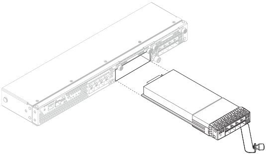 |
| 步骤 4 | To replace a network module, hold the network module in front of the network module slot on the right of the chassis and pull the network module handle out. |
| 步骤 5 | Slide the network module into the slot and push it firmly into place until the handle is flush with the front of the network module. |
| 步骤 6 | Tighten the captive screw on the lower right side of the network module. |
| 步骤 7 | Power up the chassis so that the new network module is recognized. |
接下来的操作
Follow the procedures in the FXOS Configuration Guide to connect to the network module and make sure that it has been discovered correctly by the Firepower 4100.
Remove and Replace the Fan Module
Take note of the following warnings:
警告 | Statement 60—UL- and CSA-Certified Equipment Warning This card is intended to be installed in UL- and CSA-certified equipment in the field by the user in the manufacturer's defined operator access area. Check the equipment manufacturer to verify/confirm that your equipment is suitable for user-installed application cards. |
警告 | Statement 1030—Equipment Installation Only trained and qualified personnel should be allowed to install, replace, or service this equipment. |
警告 | Statement 1040—Product Disposal Ultimate disposal of this product should be handled according to all national laws and regulations. |
警告 | Statement 1073—No User-Serviceable Parts No user-serviceable parts inside. Do not open. |
警告 | Statement 1077—Do Not Operate Unit Without Covers The covers are an integral part of the safety design of the product. Do not operate the unit without the covers installed. |
You can remove and replace fan modules while the system is running. The air flow moves from front to back. If you remove a fan or a fan fails, the other fans operate at full speed, which can be noisy.
 注 | The system supports operation with a single fan failure (N+1 fan redundancy), but do not run the system for an extended amount of time without all fan modules installed. Keep removal and replacement time at 3 minutes. Remove and replace 1 fan module at a time. |
| 步骤 1 | To remove a fan module, face the rear of the chassis, and grasp the handle of the fan module. |
| 步骤 2 | Squeeze the handle to disengage the latches on the left and right of the fan module. |
| 步骤 3 | Pull the fan
module out of the chassis.
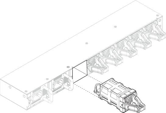 |
| 步骤 4 | To replace a fan module, hold the fan module in front of the fan slot. |
| 步骤 5 | Push the fan module into the chassis until it is properly seated and the latches snap into place. If the system is powered on, listen for the fans. You should immediately hear the fans operating. If you do not hear the fans, make sure the fan module is inserted completely into the chassis and the faceplate is flush with the outside surface of the chassis. |
| 步骤 6 | Verify that the fan is operational by checking the fan module LED. See Front Panel LEDs for a description of the fan LEDs. |
Remove and Replace the SSD
Take note of the following warnings:
警告 | Statement 60—UL- and CSA-Certified Equipment Warning This card is intended to be installed in UL- and CSA-certified equipment in the field by the user in the manufacturer's defined operator access area. Check the equipment manufacturer to verify/confirm that your equipment is suitable for user-installed application cards. |
警告 | Statement 1029—Blank Faceplates and Cover Panels Blank faceplates and cover panels serve three important functions: they prevent exposure to hazardous voltages and currents inside the chassis; they contain electromagnetic interference (EMI) that might disrupt other equipment; and they direct the flow of cooling air through the chassis. Do not operate the system unless all cards, faceplates, front covers, and rear covers are in place. |
警告 | Statement 1030—Equipment Installation Only trained and qualified personnel should be allowed to install, replace, or service this equipment. |
警告 | Statement 1040—Product Disposal Ultimate disposal of this product should be handled according to all national laws and regulations. |
警告 | Statement 1073—No User-Serviceable Parts No user-serviceable parts inside. Do not open. |
警告 | Statement 1077—Do Not Operate Unit Without Covers The covers are an integral part of the safety design of the product. Do not operate the unit without the covers installed. |
Although the hardware supports removing and replacing SSDs while the system is running, the software does not currently support hot swapping. You must power down the chassis to remove and replace SSDs.
You can install an Malware Storage Pack (MSP) in the second SSD slot (SSD slot 2). The MSP stores threat detection results for use in future analysis. It supports the Advanced Malware Protection software feature. The MSP is supported beginning in FXOS 2.0.1. It is used as both storage and as the Malware application repository. RAID is not supported.
 小心 | Do not switch the 2 SSDs. The MSP MUST be installed in slot 2. If you remove it and install it in slot 1, all stored file capture data is lost. |
| 步骤 1 | Save your configuration. | ||
| 步骤 2 | Power down the chassis by moving the power switch to the OFF position. See About the Cisco Firepower 4100 Security Appliance for more information about the power switch. | ||
| 步骤 3 | To remove an SSD, face the front of the chassis, loosen the 2 captive screws on the SSD, and gently pull it out of slot 1 of the chassis.
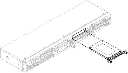 | ||
| 步骤 4 | To replace the SSD, make sure the power switch is still in the OFF position, and then hold the SSD in front of slot 1 and push it in gently until it is seated. | ||
| 步骤 5 | To install the MSP SSD, make sure the power switch is still in the OFF position and then remove the blank faceplate in Slot 2 by loosening the captive screws on either side of the faceplate. | ||
| 步骤 6 | Hold the MSP SSD
in front of slot 2 and push it in gently until it is seated.
| ||
| 步骤 7 | Tighten the captive screws on either side of the SSD. | ||
| 步骤 8 | Verify that the SSD is operational by checking the SSD LED. See Front Panel LEDs for a description of the fan LEDs. |
Remove and Replace the Power Supply Module
Take note of the following warnings:
警告 | Statement 1002—DC Power Supply When stranded wiring is required, use approved wiring terminations, such as closed-loop or spade-type with upturned lugs. These terminations should be the appropriate size for the wires and should clamp both the insulation and conductor. |
警告 | Statement 1003—DC Power Disconnection Before performing any of the following procedures, ensure that power is removed from the DC circuit. |
警告 | Statement 1005—Circuit Breaker This product relies on the building's installation for short-circuit (overcurrent) protection. Ensure that the protective device is rated not great than: AC power 120VAC, 20A (US), 240VAC, 16A (EU), DC power 60V, 35A. |
警告 | Statement 1022—Disconnect Device A readily accessible two-poled disconnect device must be incorporated in the fixed wiring. |
警告 | Statement 1025—Use Copper Conductors Only Use copper conductors only. |
警告 | Statement 1028—More Than One Power Supply This unit might have more than one power supply connection. All connections must be removed to de-energize the unit. |
警告 | Statement 1030—Equipment Installation Only trained and qualified personnel should be allowed to install, replace, or service this equipment. |
警告 | Statement 1040—Product Disposal Ultimate disposal of this product should be handled according to all national laws and regulations. |
警告 | Statement 1045—Short-circuit Protection This product requires short-circuit (overcurrent) protection to be provided as part of the building installation. Install only in accordance with national and local wiring regulations. |
警告 | Statement 1046—Installing or Replacing the Unit When installing or replacing the unit, the ground connection must always be made first and disconnected last. |
警告 | Statement 1073—No User-Serviceable Parts No user-serviceable parts inside. Do not open. |
警告 | Statement 1077—Do Not Operate Unit Without Covers The covers are an integral part of the safety design of the product. Do not operate the unit without the covers installed. |
You can remove and replace power supply modules while the system is running.
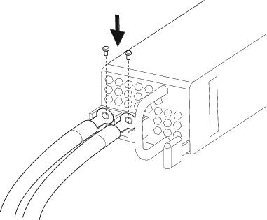
| 步骤 1 | To remove a power supply module, face the back of the chassis and grasp the handle. |
| 步骤 2 | Press the latch found on the lower right of the power supply to disengage the power supply. |
| 步骤 3 | Place your
other hand under the power supply module to support it while you slide it out
of the chassis.
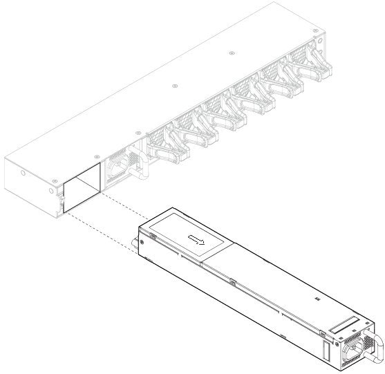 |
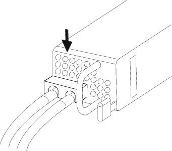
| 步骤 4 | To replace a power supply module, hold the power supply module with both hands and slide it into the power supply module bay. |
| 步骤 5 | Push in the power supply module gently until you hear the latch engage and it is seated. Verify the power supply module is operating correctly by checking the power supply module LED. See Power Supply Modules for a description of the power supply module LEDs. |
Connect the DC Power Supply Module
Take note of the following warnings:
警告 | Statement 1002—DC Power Supply When stranded wiring is required, use approved wiring terminations, such as closed-loop or spade-type with upturned lugs. These terminations should be the appropriate size for the wires and should clamp both the insulation and conductor. |
警告 | Statement 1003—DC Power Disconnection Before performing any of the following procedures, ensure that power is removed from the DC circuit. |
警告 | Statement 1005—Circuit Breaker This product relies on the building's installation for short-circuit (overcurrent) protection. Ensure that the protective device is rated not great than: AC power 120VAC, 20A (US), 240VAC, 16A (EU), DC power 60V, 35A. |
警告 | Statement 1017—Restricted Area This unit is intended for installation in restricted access areas. A restricted access area can be accessed only through the use of a special tool, lock and key, or other means of security. |
警告 | Statement 1022—Disconnect Device A readily accessible two-poled disconnect device must be incorporated in the fixed wiring. |
警告 | Statement 1025—Use Copper Conductors Only Use copper conductors only. |
警告 | Statement 1028—More Than One Power Supply This unit might have more than one power supply connection. All connections must be removed to de-energize the unit. |
警告 | Statement 1030—Equipment Installation Only trained and qualified personnel should be allowed to install, replace, or service this equipment. |
警告 | Statement 1040—Product Disposal Ultimate disposal of this product should be handled according to all national laws and regulations. |
警告 | Statement 1045—Short-circuit Protection This product requires short-circuit (overcurrent) protection to be provided as part of the building installation. Install only in accordance with national and local wiring regulations. |
警告 | Statement 1046—Installing or Replacing the Unit When installing or replacing the unit, the ground connection must always be made first and disconnected last. |
警告 | Statement 1077—Do Not Operate Unit Without Covers The covers are an integral part of the safety design of the product. Do not operate the unit without the covers installed. |
警告 | Statement 1073—No User-Serviceable Parts No user-serviceable parts inside. Do not open. |
警告 | Statement 1086—Power Terminals, Replace Cover Hazardous voltage or energy may be present on power terminals. Always replace cover when terminals are not in service. Be sure uninsulated conductors are not accessible when cover is in place. |
Each DC input power cable is terminated at the PDU by a cable lug, as shown in the following figure.
注 | DC input power cables must be connected to the PDU terminal studs in the proper positive (+) and negative (–) polarity. In some cases, the DC cable leads are labeled, which is a relatively safe indication of the polarity. However, you must verify the polarity by measuring the voltage between the DC cable leads. When making the measurement, the positive (+) lead and the negative (–) lead must always match the (+) and (–) labels on the power distribution unit. |
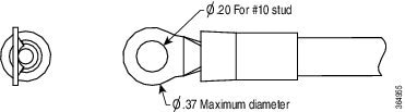
注 | To avoid hazardous conditions, all components in the area where DC input power is accessible must be properly insulated. Therefore, before installing the DC cable lugs, be sure to insulate the lugs according to the manufacturer's instructions |
This procedure describes how to install the DC power supply input power leads to the Firepower 4100 DC input power supply on the rear PDU of the chassis.
-
The color coding of the DC input power supply leads depends on the color coding of the DC power source at your site. Make sure that the lead color coding you choose for the DC input power supply matches the lead color coding used at the DC power source and verify that the power source is connected to the negative (–) terminal and to the positive (+) terminal on the power supply.
-
For DC input power cables, the wire gauge is based on the National Electrical Code (NEC) and local codes for 26 amp service at nominal DC input voltage (–40/–72 VDC). One pair of cable leads, source DC (–) and source DC return (+), are required for each power distribution unit (PDU). These cables are available from any commercial cable vendor. All DC input power cables for the chassis should be 10gauge wire and cable lengths should match within 10 percent of deviation.
-
Tools needed:
| 步骤 1 | Install the DC power supply module in the chassis and make note of the bay number so you can connect the wiring to the correct terminals on the DC power supply module at the rear of the chassis. See Remove and Replace the Power Supply Module for the procedure. |
| 步骤 2 | Verify that the power is off to the DC circuit on the power supply module that you are installing. |
| 步骤 3 | Make sure that all site power and grounding requirements have been met. |
| 步骤 4 | To remove the
plastic cover from the terminal block, insert a flat screw driver on the side
of the plastic cover and pry it off.
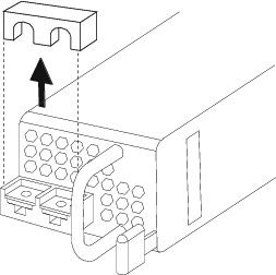
|
| 步骤 5 | To prevent any contact with metal lead on the ground wire and the plastic cover, you must wrap the positive and negative lead cables with sleeving. Insulate the lug with shrink sleeving for each lead wire if using noninsulated crimp terminals. Sleeving is not required for insulated terminals. |
| 步骤 6 | Remove the two
M5 screws.
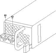
|
| 步骤 7 | For easier cable
management, insert the negative lead cable first. Replace the grounding lug
with the cable in the following order—wire terminal, then the screw with the
captive washer.
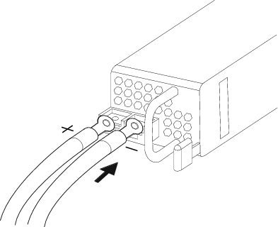
|
| 步骤 8 | Tighten the M5
screw with the captive washer to the recommended torque of 5 in-lbs for the
positive stud and wire. Secure the wires coming in from the terminal block so
that they cannot be disturbed by casual contact.
|
| 步骤 9 | Replace the
terminal block plastic cover. The plastic cover is slotted and keyed to fit
correctly over the terminal block. This cover should always be in place when
power is applied to the terminals.
|
| 步骤 10 | Set the DC disconnect switch in the circuit to ON. In a system with multiple power supplies, connect each power supply to a separate DC power source. In the event of a power source failure, if the second source is still available, it can maintain system operation. |
| 步骤 11 | Verify power supply operation by checking the power supply LED on the front of the chassis. See Front Panel LEDs for a description of the the LEDs. |
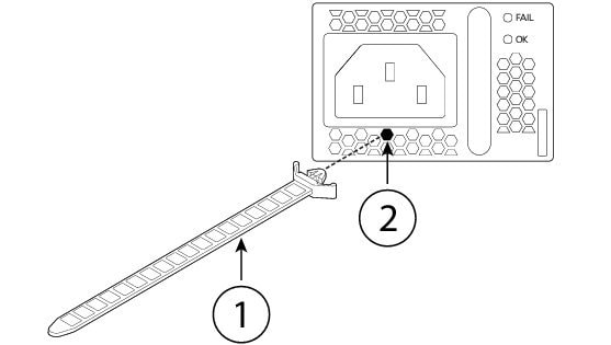
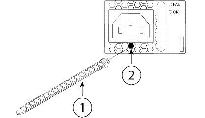
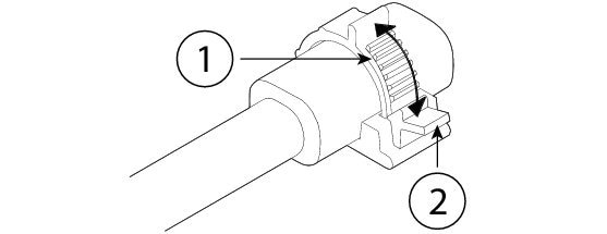
Secure the Power Cord on the AC Power Supply Module
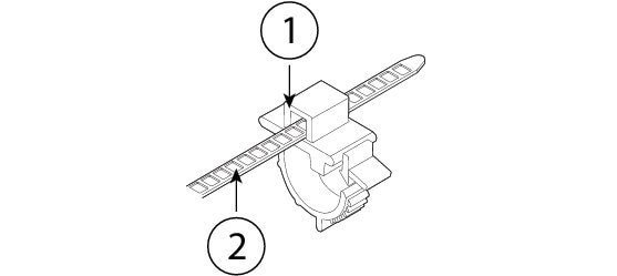
To secure the power supply module against accidental removal and thus prevent disrupting system performance, use the tie wrap and clamp provided in the accessories kit that ships with your Firepower 4100. There are two different tie wrap and clamp combinations to be used with either the Flextronics or Artesyn power supply module.
To verify which power supply module you have, look at the vendor name on the top of the power supply module. If you cannot remove the power supply module, you can count the number of full hexagonal vent holes on the front of the power supply module in the row directly next to the word 'FAIL.' Flextronics has five holes and Artesyn has four holes.
The black tie wrap is used with the Flextronics power supply module and the off-white tie wrap is used with the Artesyn power supply module. The black clamp works with both. See the figures below.
Take note of the following warnings:
警告 | Statement 1030—Equipment Installation Only trained and qualified personnel should be allowed to install, replace, or service this equipment. |
警告 | Statement 1073—No User-Serviceable Parts No user-serviceable parts inside. Do not open. |
 反馈
反馈