Cisco Firepower 4110、4120、4140 和 4150 硬件安装指南
非歧视性语言
此产品的文档集力求使用非歧视性语言。在本文档集中,非歧视性语言是指不隐含针对年龄、残障、性别、种族身份、族群身份、性取向、社会经济地位和交叉性的歧视的语言。由于产品软件的用户界面中使用的硬编码语言、基于 RFP 文档使用的语言或引用的第三方产品使用的语言,文档中可能无法确保完全使用非歧视性语言。 深入了解思科如何使用包容性语言。
当地语言翻译版本说明
思科可能会在某些地方提供本内容的当地语言翻译版本。请注意,翻译版本仅供参考,如有任何不一致之处,以本内容的英文版本为准。
- 已更新:
- 2021年2月12日
Chapter: Overview
Overview
This chapter describes the hardware features of the Cisco Firepower 4100 security appliance, and contains the following sections:
- About the Cisco Firepower 4100 Security Appliance
- Deployment Options
- Package Contents
- Serial Number Location
- Front Panel
- Front Panel LEDs
- Rear Panel
- Network Modules
- Power Supply Modules
- Fan Modules
- Supported SFP/SFP+ Transceivers
- Power Cord Specifications
- Hardware Specifications
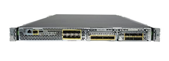
About the Cisco Firepower 4100 Security Appliance
The Cisco Firepower 4100 security appliance is a standalone modular security services platform with a one RU form factor. It is capable of running multiple security services simultaneously and so is targeted at the data center as a multi-service platform. The Firepower 4100 chassis contains the following components:
-
Network module 1 with eight fixed SFP+ ports (1G and 10G connectivity), the management port, RJ-45 console port, Type A USB port, PID and S/N card, locator indicator, and power switch
-
Two network modules slots (network module 2 and network module 3)
-
Two (1+1) redundant power supply module slots
-
Six fan module slots
-
Two SSD bays

注
RAID is not supported.
The network modules, power supply modules, fan modules and SSDs are FRUs (field replaceable units). The power supply modules and the fan modules are hot-swappable. Although the hardware supports hot swapping for the SSDs and network modules, the software does not, so you must power down the chassis before removing and replacing them.
You can install an MSP (Malware Storage Pack) in the second SSD slot (SSD slot 2). The MSP stores threat detection results for use in future analysis. It supports the Advanced Malware Protection software feature. It is used as both storage and as the Malware application repository.
 小心 | Do not switch the two SSDs. The MSP MUST be installed in slot 2. If you remove it and install it in slot 1, all stored file capture data are lost. |
The Firepower 4100 is a one RU chassis designed to fit in a 19-inch rack using rack mount slides. The ports are located on the front (cold aisle) and the power supplies, power entry, and fans are in the rear. Air flow is from front to rear (cold aisle to hot aisle).
- Power Switch
-
The power switch is located to the left of power supply module 1 on the rear of the chassis. It is a toggle switch that controls power to the system. If the power switch is in standby position, only the 3.3V standby power is enabled from the power supply module and the 12V main power is OFF. When the switch is in the ON position, the 12V main power is turned on and the system boots.
Before you move the power switch to the OFF position, use the shutdown commands so that the system can perform a graceful shutdown. This may take several minutes to complete. After the graceful shutdown is completed, the front panel power LED is unlit and the console displays Power Down.
注
The shutdown commands are first available in Firepower eXtensible Operating System (FXOS) version 2.0.1. See the FXOS Configuration Guide for more information on using these commands.
小心
If you move the power switch to the OFF position before the shutdown command sequence has completed or if you remove the system power cords before the graceful shutdown is complete, disk corruption can occur.
The Firepower 4100 has the following hardware configurations.
- Firepower 4110
-
The Firepower 4110 has a single 12-core processor, one AC power supply module, one 200-GB SSD, and 64-GB of DDR4 RAM. You can add another power supply module for redundant power.
The second SSD bay is reserved for the MSP SSD.
- Firepower 4120
-
The Firepower 4120 has dual 12-core processors, one AC power supply module, one 200-GB SSD, and 128-GB of DDR4 RAM. You can add another power supply module for redundant power.
The second SSD bay is reserved for the MSP SSD.
注
The Firepower 4120 is NEBS-certified.
- Firepower 4140
-
The Firepower 4140 has dual 18-core processors, dual AC power supply modules, one 400-GB SSD, and 256-GB of DDR4 RAM.
The second SSD bay is reserved for the MSP SSD.
- Firepower 4150
-
The Firepower 4150 has a dual 22-core processor, dual redundant AC power supply modules, one 400-GB SSD in slot 1, and 256-GB of DDR4 RAM. The second SSD bay is reserved for the MSP SSD.
Deployment Options
You can deploy the Firepower 4100 in the following ways:
-
In a data center using NGFW and ASA
-
At the core/aggregation layer of a three-tier data center in an HA configuration
-
As a dedicated multi-functional security service within converged infrastructure stacks, for example, vBlock, FlexPod, and so forth, at the access layer
-
As a high-performance data center security appliance between the WAN edge and the data center core in an HA configuration
-
Inter-DC clustering deployments
-
In newer spine/leaf data center designs, deployment as a leaf that exclusively offers security functions
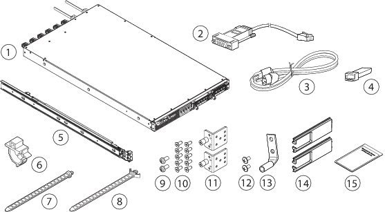
Package Contents
The following figure shows the package contents for the Firepower 4100 series security appliance. Note that the contents are subject to change and your exact contents might contain additional or fewer items.
|
1 |
Firepower 4100 chassis |
2 |
Blue console cable PC terminal adapter |
|
3 |
Two power cords (country-specific) |
4 |
10/100/1000BASE-T SFP transceiver |
|
5 |
Two slide rails |
6 |
Tie wrap clamp |
|
7 |
Artesyn tie wrap |
8 |
Flextronics tie wrap |
|
9 |
Two M3X6mm screws used to secure the inner slide rail to the chassis |
10 |
Ten 8-32 x .375" countersink screws used to secure the mounting bracket to chassis (6 screws), and the cable management brackets to the mounting brackets (4 screws) |
|
11 |
Two slide rail locking brackets |
12 |
Two 10-32 x .375" screws used to secure the ground lug |
|
13 |
One ground lug #6 AWG, 90 degree, #10 post |
14 |
Two cable management brackets |
|
115 |
Welcome to the Cisco Firepower 4100 |
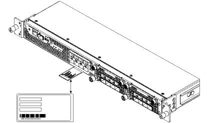
Serial Number Location
The serial number for the Firepower 4100 series chassis is located on the pull-out label card on the front panel.
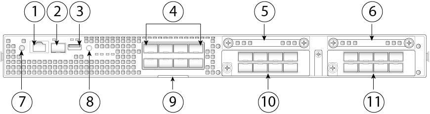
Front Panel
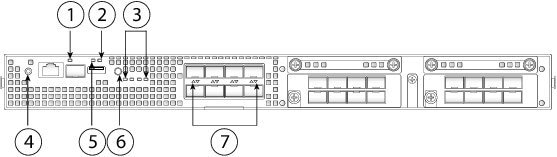
The following figure shows the front panel of the Firepower 4100 series security appliance.
|
1 |
RJ-45 console port |
2 |
Gigabit Ethernet management port |
||
|
3 |
Type A USB port |
4 |
Eight fixed SFP+ (1G/10G) ports are provided (network module slot 1) Gigabit Ethernet 1/1 through 1/8 labeled top to bottom, left to right |
||
|
5 |
SSD 1 |
6 |
SSD 2 |
||
|
7 |
Power LED |
8 |
Locator LED |
||
|
9 |
Pull-out label card |
10 |
Network Module (network module slot 2)
|
||
|
11 |
Network Module (network module slot 3)
|
Front Panel LEDs
The following figure and table describe the Firepower 4100 series security appliance front panel LEDs.
|
1 |
Management |
2 |
Health (SYS) |
|
3 |
SSD |
4 |
Power |
|
5 |
Activity (ACT) |
6 |
Locator LED |
|
7 |
Network activity |
Rear Panel
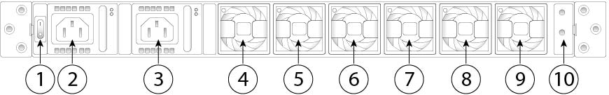
The following figure shows the rear panel of the Firepower 4100 series security appliance.
|
1 |
Power on/off switch |
2 |
Power supply module 1 |
||
|
3 |
Power supply module 2 |
4 |
Fan module 1 |
||
|
5 |
Fan module 2 |
6 |
Fan module 3 |
||
|
7 |
Fan module 4 |
8 |
Fan module 5 |
||
|
9 |
Fan module 6 |
10 |
Location for the two-post grounding lug
|
Network Modules
The FirePower 4100 security appliance contains two network module slots that provide optical or electrical network interfaces. Network modules are optional, removable I/O modules that provide either additional ports or different interface types (1/10/40G). The Firepower network modules plug into the chassis on the front panel.
Some network modules also offer Hardware Bypass functionality, also known as Fail-to-Wire (FTW), for interface pairs for supported applications. FTW is a physical layer bypass that allows interface port pairs to be put in bypass mode so that the hardware forwards packets without software intervention.
注 | The network modules are NOT hot-swappable. |
-
Firepower 8-port 10G SPF+ Network Module single-wide (FPR4K-NM-8X10G)
The 10 Gigabit Ethernet network module ports are numbered from top to bottom, left to right. This network module is NEBS-compliant.
-
Firepower 4-port 40G QSPF Network Module single-wide (FPR4K-NM-4X40G)
The 40 Gigabit Ethernet network module ports are numbered left to right. This network module is NEBS-compliant.
-
Firepower 2-port 40G FTW Network Module single-wide (FPR-NM-2X40G-F)
The 40 Gigabit Ethernet network module ports are numbered left to right.
-
Firepower 6-port 10G Short Reach FTW Network Module single-wide (FPR-NM-6X10SR-F)
The 10 Gigabit Ethernet network module ports are numbered from top to bottom, left to right.
-
Firepower 6-port 10G Long Reach FTW Network Module single-wide (FPR-NM-6X10LR-F)
The 10 Gigabit Ethernet network module ports are numbered from top to bottom, left to right.
-
Firepower 6-port 1G SX Fiber FTW Network Module single-wide (FPR-NM-6X1SX-F)
The 1 Gigabit Ethernet network module ports are numbered from top to bottom, left to right.
-
Firepower 8-port 1G 1000Base-T FTW Network Module single-wide ( FPR-NM-8X1G-F)
The 1 Gigabit Ethernet network module ports are numbered from top to bottom, left to right. This network module is NEBS-compliant.
- For More Information
-
-
See Nonhardware (FTW) Bypass Network Modules for the location and description of the LEDs for the nonhardware bypass network modules.
-
See Hardware Bypass (FTW) Network Modules for the location and description of the LEDs, and the port configurations for the hardware bypass network modules.
-
See Remove and Replace the Network Module for the procedure for removing and replacing network modules.
-
Nonhardware (FTW) Bypass Network Modules
The Firepower 4100 supports two nonhardware bypass modules, the 10G and the 40G.
The following figure shows the front panel view of the 10G network module.
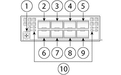
|
1 |
Captive screw/handle |
2 |
Ethernet X/1 |
|
3 |
Ethernet X/3 |
4 |
Ethernet X/5 |
|
5 |
Ethernet X/7 |
6 |
Ethernet X/2 |
|
7 |
Ethernet X/4 |
8 |
Ethernet X/6 |
|
9 |
Ethernet X/8 |
10 |
Network activity LEDs |
注 | You can fit four copper SFPs in either the top row of ports or the bottom row of ports. Both rows cannot be populated at the same time, because the SFP ports are too close together for the copper SFPs to fit on both the top and the bottom row at the same time. For a list of copper SFPS, see Supported SFP/SFP+ Transceivers. |
The following figure shows the front panel view of the 40G network module.
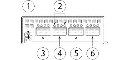
|
1 |
Captive screw/handle |
2 |
Network activity LEDs |
|
3 |
Ethernet X/1 |
4 |
Ethernet X/2 |
|
5 |
Ethernet X/3 |
6 |
Ethernet X/4 |
- For More Information
-
-
See Hardware Bypass (FTW) Network Modules for the location and description of the LEDs, and the port configurations for the hardware bypass network modules.
-
See Remove and Replace the Network Module for the procedure for removing and replacing network modules.
-
Hardware Bypass (FTW) Network Modules
Fail-to-Wire (FTW) is a physical layer (Layer 1) bypass that allows paired interfaces to go into bypass mode so that the hardware forwards packets between these port pairs without software intervention. FTW provides network connectivity when there are software or hardware failures. Hardware bypass is useful on ports where the Firepower security appliance is only monitoring or logging traffic. The hardware bypass network modules have an optical switch that is capable of connecting the two ports when needed.
The FTW network modules have built-in SFPs.
Hardware bypass is supported only on a fixed set of ports. You can pair Port 1 with Port 2, Port 3 with Port 4, but you cannot pair Port 1 with Port 4 for example.
注 | Hardware bypass is only supported in inline mode. Also, hardware bypass support depends on your software application. |
注 | When switching from normal operation to hardware bypass or from hardware bypass back to normal operation, traffic may be interrupted for several seconds. A number of factors can affect the length of the interruption; for example, copper port autonegotiation; behavior of the optical link partner such as how it handles link faults and debounce timing; spanning tree protocol convergence; dynamic routing protocol convergence; and so on. During this time, you may experience dropped connections. |
-
Passive interfaces—Connection to a single port.
For each network segment you want to monitor passively, connect the cables to one interface. This is how the non FTW network modules operate.
-
Inline interfaces—Connection to any two like ports (10G to 10G for example) on one network module, across network modules, or fixed ports.
For each network segment you want to monitor inline, connect the cables to pairs of interfaces.
-
Inline with FTW interfaces—Connection of an FTW paired set.
For each network segment that you want to configure inline with fail-open, connect the cables to the paired interface set.
For the 40G network module, you connect the two ports to form a paired set. For the 1/10G network modules, you connect the top port to the bottom port to form an FTW paired set. This allows traffic to flow even if the Firepower security appliance fails or loses power.
注 | If you have a inline interface set with a mix of FTW-capable and non FTW-capable interfaces, you cannot enable hardware bypass on this inline interface set. You can only enable hardware bypass on an inline interface set if all the pairs in the inline set are valid FTW pairs. |
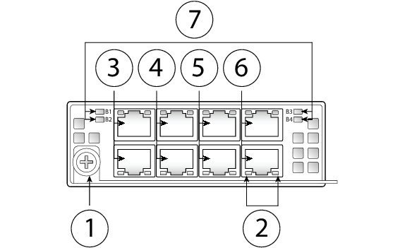
The following figure shows the front panel view of the 1G FTW network module. Pair ports 1 and 2, 3 and 4, 5 and 6, and 7 and 8 to form hardware bypass paired sets.
|
1 |
Captive screw/handle |
2 |
Eight Network activity LEDs |
|
3 |
Ethernet X/1 Ports 1 and 2 are paired together to form a hardware bypass pair. LED B1 applies to this paired port. |
4 |
Ethernet X/2 Ports 3 and 4 are paired together to form a hardware bypass pair. LED B2 applies to this paired port. |
|
5 |
Ethernet X/2 Ports 5 and 6 are paired together to form a hardware bypass pair. LED B3 applies to this paired port. |
6 |
Ethernet X/2 Ports 7 and 8 are paired together to form a hardware bypass pair. LED B4 applies to this paired port. |
|
|
Bypass LEDs B1 through B4 |
|
|
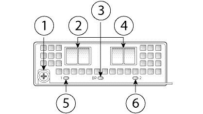
The following figure shows the front panel view of 40G FTW network module. Pair the two ports to create a hardware bypass paired set.
|
1 |
Captive screw/handle |
2 |
Ethernet X/1 Ports 1 and 2 are paired together to form a hardware bypass pair. |
|
3 |
Bypass LED BP |
4 |
Ethernet X/2 Ports 1 and 2 are paired together to form a hardware bypass pair. |
|
5 |
Network activity LEDs |
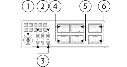
The following figure shows the front panel view of the 1G SX, 10G SR, and 10G LR FTW network module. Pair ports 1 and 2, 3 and 4, and 5 and 6 to form hardware bypass paired sets.
|
1 |
Captive screw/handle |
2 |
Six Network activity LEDs |
|
3 |
Bypass LEDs B1 through B3 |
4 |
Ethernet X/1 (top port) Ethernet X/2 (bottom port) Ports 1 and 2 are paired together to form a hardware bypass pair. |
|
5 |
Ethernet X/3 (top port) Ethernet X/4 (bottom port) Ports 3 and 4 are paired together to form a hardware bypass pair. |
6 |
Ethernet X/5 (top port) Ethernet X/6 (bottom port) Ports 5 and 6 are paired together to form a hardware bypass pair. |
1G SX/10G SR/10G LR Network Module Insertion Loss
The 1G SX /10G SR/10G LR network module has the following insertion loss measurements. Insertion loss measurements help you to troubleshoot the network by verifying cable installation and performance.
|
|
Operating Mode |
Typical |
Maximum |
||
|
Insertion loss |
Normal Hardware bypass |
0.9 dB 1.2 dB |
1.4 dB 1.7 dB |
||
|
|
Core Diameter (microns) |
Modal Bandwidth (MHz/km |
Cable Distance
|
||
|
Cable and operating distance |
62.5 62.5 50 50 50 |
160 (FDDI) 200(OM1) 400 500 (OM2) 2000 (OM3) |
110 m 137 m 250 m 275 m 500 m |
|
|
Operating Mode |
Typical |
Maximum |
||
|
Insertion loss |
Normal Hardware bypass |
0.9 dB 1.2 dB |
1.4 dB 1.7 dB |
||
|
|
Core Diameter (microns) |
Modal Bandwidth (MHz/km |
Cable Distance
|
||
|
Cable and operating distance |
62.5 62.5 50 50 50 50 |
160 (FDDI) 200(OM1) 400 500 (OM2) 2000 (OM3) 4700 (OM4) |
13 m 16.5 m 33 m 41 m 150 m 200 m |
|
|
Operating Mode |
Typical |
Maximum |
||
|
Insertion loss |
Normal Hardware bypass |
1.2 dB 1.5 dB |
1.6 dB 1.9 dB |
||
|
|
Core Diameter (microns) |
Modal Bandwidth (MHz/km |
Cable Distance
|
||
|
Cable and operating distance |
G.652 |
Single mode |
5 m |
- For More Information
-
-
See Nonhardware (FTW) Bypass Network Modules for the location and description of the LEDs, and the port configurations for the non-hardware bypass network modules.
-
See Remove and Replace the Network Module for the procedure for removing and replacing network modules.
-
Power Supply Modules
The Firepower 4100 security appliance supports two AC or DC power supply modules so that dual power supply redundancy protection is available. Facing the back of the chassis, the power supply modules are numbered left to right, for example, PSU-1 and PSU-2.
注 | The system power requirements are lower than the power supply module capabilities. See Hardware Specifications for the system power requirements. |
Make sure that one power supply module is always active.
See Remove and Replace the Power Supply Module for the procedure for removing and replacing the power supply module.
AC Power Supply
The power supplies can supply up to 1100W power across the input voltage range. The load is shared when both power supply modules are plugged in and running at the same time. The power supply modules are hot-swappable.
|
Input voltage |
100 to 240V AC |
||
|
Maximum current |
13A (at 100V AC)
|
||
|
Maximum output power |
1100W |
||
|
Frequency |
50 to 60Hz |
||
|
Redundancy |
1+1 redundant |
||
|
Efficiency at 50% load |
92% |
DC Power Supply
The power supplies can supply up to 950W power across the input voltage range. The load is shared when both power supply modules are plugged in and running at the same time. The power supply modules are hot-swappable.
|
Input voltage |
-40 to -60V DC |
||
|
Maximum current |
26A (at 40V DC)
|
||
|
Maximum output power |
950W |
||
|
Redundancy |
1+1 redundant |
||
|
Efficiency at 50% load |
92% |
Power Supply Module LEDs
The following figure shows the bicolor power supply LEDs. The LEDs are located on the upper right side.
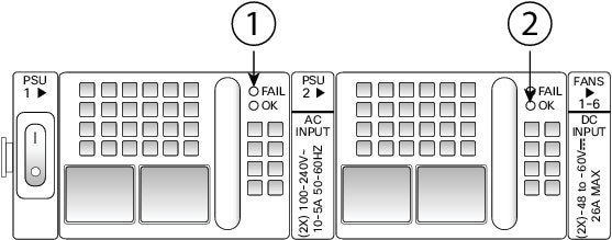
|
1 |
Amber FAIL LED |
2 |
Green OK LED |
The following table describes the power module supply LEDs.
|
|
Amber LED (Fail Status) |
Green LED (OK Status) |
|
No power to all power supplies |
Off |
Off |
|
Power supply module failure Includes over voltage, over current, over temperature, and fan failure |
On |
Off |
|
Power supply module warning events Power supply continues to operate (high temperature, high power, and slow fan) |
1 Hz blinking |
Off |
|
Power present 3.3VSB on (power supply module off) |
Off |
1 Hz blinking |
|
Power supply module ok and on |
Off |
On |
Fan Modules
The Firepower 4100 security appliance requires six fan modules, which are hot-swappable. They are installed in the rear of the chassis. The system supports operation with a single fan failure (N+1 fan redundancy), but do not run the system for an extended amount of time without all fan modules installed. Keep removal and replacement time at three minutes. Remove and replace one fan module at a time.
If you remove a fan or a fan fails, the other fans operate at full speed, which can be noisy.
The fan modules are numbered left to right, for example, FAN1, FAN2, FAN3, FAN4, FAN5, and FAN6. See Remove and Replace the Fan Module for the procedure for removing and replacing the fan module.
The following figure shows the location of the fan LED.

|
1 |
Bicolor LED |
|
The fan module has one bicolor LED, which is located on the upper left corner of the fan.
Supported SFP/SFP+ Transceivers
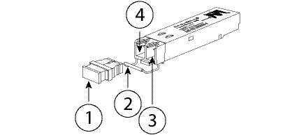
The Small Form-Factor Pluggable (SFP/SFP+) transceivers are bidirectional devices with a transmitter and receiver in the same physical package. It is a hot-swappable optical or electrical (copper) interface that plugs into the SFP/SFP+ ports on the fixed ports and the network module ports, and provides Ethernet connectivity.
 警告 | Use appropriate electrostatic discharge (ESD) procedures when inserting the transceiver. Avoid touching the contacts at the rear, and keep the contacts and ports free of dust and dirt. Keep unused transceivers in the ESD packing that they were shipped in. The following figure shows a sample SFP transceiver. |
|
1 |
Dust plug |
2 |
Bail clasp |
|
3 |
Receive optical bore |
4 |
Transmit optical bore |
小心 | Although non-Cisco SFPs are allowed, we do not recommend using them because they have not been tested and validated by Cisco. Cisco TAC may refuse support for any interoperability problems that result from using an untested third-party SFP transceiver. |
小心 |
For some earlier production Firepower 4100 series chassis, you may experience difficulty using the GLC-TE SFP on the management port or fixed ports. Contact Cisco TAC for support if you encounter problems with the GLC-TE SFP. |
The following table lists the Cisco supported transceivers.
|
Optics Type |
PID |
|
1G |
|
|
1G-SX |
GLC-SX-MMD |
|
1G-LH/LX |
GLC-LH-SMD |
|
1G-EX |
GLC-EX-SMD |
|
1G-ZX |
GLC-ZX-SMD |
|
1G 1000Base-T |
GLC-T |
|
1G 1000Base-T |
GLC-TE |
|
10G |
|
|
10G-SR |
SFP-10G-SR |
|
10G-SR-S |
SFP-10G-SR-S |
|
10G-LR |
SFP-10G-LR |
|
10G-LR-S |
SFP-10G-LR-S |
|
10G-LRM |
SFP-10G-LRM |
|
10G-ER |
SFP-10G-ER |
|
10G-ER-S |
SFP-10G-ER-S |
|
10G-ZR-S |
SFP-10G-ZR-S |
|
10G Cu, 1m |
SFP-H10GB-CU1M |
|
10G Cu, 1.5m |
SFP-H10GB-CU1-5M |
|
10G Cu, 2m |
SFP-H10GB-CU2M |
|
10G Cu, 2.5m |
SFP-H10GB-CU2-5M |
|
10G Cu, 3m |
SFP-H10GB-CU3M |
|
10G Cu, 5m |
SFP-H10GB-CU5M |
|
10G Cu, 7m |
SFP-H10GB-ACU7M |
|
10G Cu, 10m |
SFP-H10GB-ACU10M |
|
10G AOC, 1m |
SFP-10G-AOC1M |
|
10G AOC, 2m |
SFP-10G-AOC2M |
|
10G AOC, 3m |
SFP-10G-AOC3M |
|
10G AOC, 5m |
SFP-10G-AOC5M |
|
10G AOC, 7m |
SFP-10G-AOC7M |
|
10G AOC, 10m |
SFP-10GAOC10M |
|
40G |
|
|
40G-SR4 |
QSFP-40G-SR4 |
|
40G-SR4-S |
QSFP-40G-SR4-S |
|
40G-CSR4 |
QSFP-40G-CSR4 |
|
40G-SR-BD |
QSFP-40G-SR-BD |
|
40GE-LR4 |
QSFP-40GE-LR4 |
|
40GE-LR4-S |
QSFP-40GE-LR4-S |
|
40G-LR4L |
WSP-Q40GLR4L |
|
40G-CU, 1M, 3M, 5M |
QSFP-H40G-CU |
|
40G-4X10G-CU, 1M, 3M, 5M |
QSFP-4SFP10G-CU |
|
40G-CU-A, 7M, 10M |
QSFP-H40G-ACU |
|
40G-4X10G-CU-A, 7M, 10M |
QSFP-4X10G-AC |
|
40G-AOC, 1M, 2M, 3M, 5M, 7M, 10M, 15M |
QSFP-H40G-AOC |
Power Cord Specifications
Each power supply has a separate power cord. Standard power cords are available for connection to the security appliance.
If you do not order the optional power cord with the system, you are responsible for selecting the appropriate power cord for the product. Using a non-compatible power cord with this product may result in electrical safety hazard. Orders delivered to Argentina, Brazil, and Japan must have the appropriate power cord ordered with the system.
Only the approved power cords provided with the security appliance are supported. The following table lists the supported power cords.
|
Description |
Amperage |
Voltage |
Plug |
Connector |
|
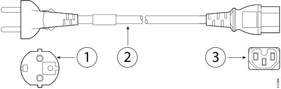
CAB-AC-EUR Power cord (Europe) See Figure 15 below. |
10A |
250V |
C33 7/7 |
IEC 60320-C15 |
|
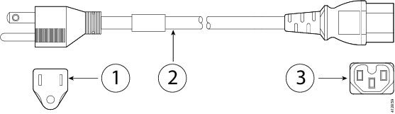
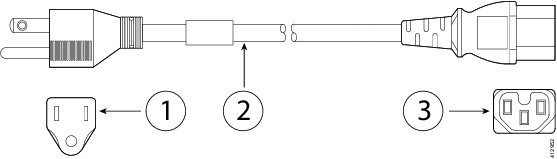
CAB-TA-NA AC Type A power cord (North America) See Figure 16 below. |
12A |
125V |
NEMA 5-15P |
IEC 60320-C15 |
|
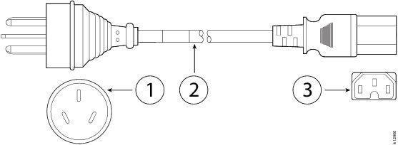
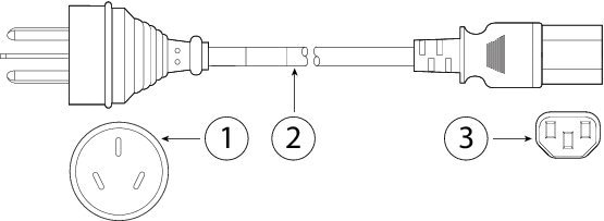
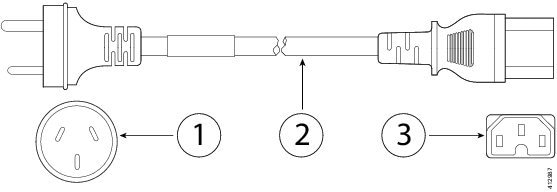
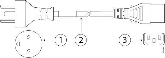
CAB-9K10A-AU AC power cord (Australia) See Figure 17 below. |
10A |
250V |
A.S. 3112-2000 |
IEC 60320-C15 |
|
CAB-9K10A-IT AC power cord (Italy) See Figure 18 below. |
10A |
250V |
CEI 23-16/VII |
IEC 60320-C15 |
|
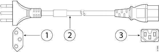
CAB-9K10A-AR AC power cord (Argentina) See Figure 19 below. |
10A |
250V |
IRAM 2073 |
IEC 60320-C15 |
|
CAB-9K10A-SW AC power cord (Switzerland) See Figure 20 below. |
10A |
250V |
SEV 1011 |
IEC 60320-C15 |
|
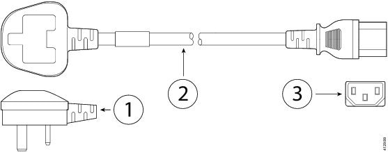
CP-PWR-CORD-UK Power cord (United Kingdom) See Figure 21 below. |
10A |
250V |
BS1363A/SS145 |
IEC 60320-C13 |
|
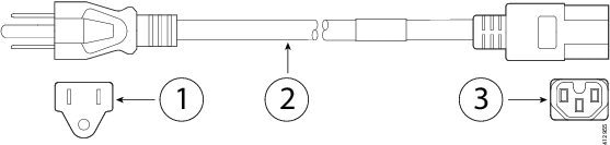
CAB-TA-JP AC Type A power cord (Japan) See Figure 22 below. |
12A |
125V |
NEMA5-15P/JIS C8303 |
IEC 60320-C15 |
|
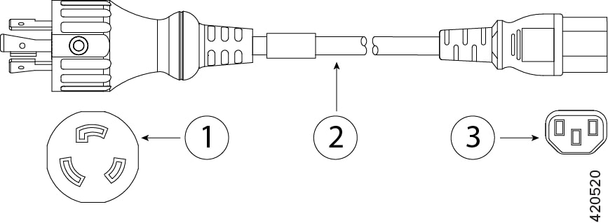
CAB-L620P-C13-JPN 15A/250V cable (Japan) See Figure 23 below. |
15A |
250V |
NEMA L6-20P |
IEC 60320-C13 |
|
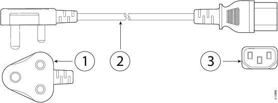
CAB-9K10A-SA AC power cord (South Africa) See Figure 24 below. |
10A |
250V |
SABS 164 |
IEC 60320-C15 |
|
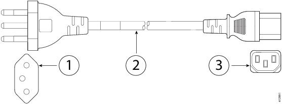
CAB-9K10A-CH AC power cord (China) See Figure 25 below. |
10A |
250V |
CCC GB2009.1, GB1002 |
IEC 60320-C15 |
|
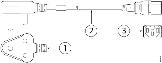
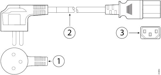
CAB-250V-10A-ID AC power cord (India) See Figure 26 below. |
10A |
250V |
IS 6538-1971 |
IEC 60320-C13 |
|
PWR-CORD-G2A-BZ Telepresence G2A power cord (Brazil) See Figure 27 below. |
10A |
250V |
NBR 14136 |
IEC 60320-C13 |
|
CAB-9K10A-TWN AC power cord (Taiwan) See Figure 28 below. |
10A |
125V |
CNS10917-2 |
IEC 60320-C15 |
|
CAB-250V-10A-IS AC power cord (Israel) See Figure 29 below. |
10A |
250V |
SI-32 |
IEC 60320-C13 |
|
UNITY-PWR-DEN Standard power cord (Denmark) See Figure 30 below. |
10A |
250V |
IEC 60884-1 |
IEC 60320-C13 |
|
ATA187PWRCORD-SAUD ATA187 power cord (Saudi Arabia) See Figure 31 below. |
10A |
250V |
BS1363A/SS145 |
IEC 60320-C13 |
The following figures show the cord, connector, and plug for each country listed in the table above.
|
1 |
Plug: CEE 7/7 |
2 |
Cord set rating: 10A, 250V |
|
3 |
Connector: IEC 60320-C15 |
|
1 |
Plug: NEMA5-15P |
2 |
Cord set rating: 12A, 125V |
|
3 |
Connector: IEC 60320-C15 |
|
1 |
Plug: A.S. 3112-2000 |
2 |
Cord set rating: 10A, 250V |
|
3 |
Connector: IEC 60320-C15 |
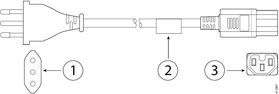
|
1 |
Plug: CEI 23-16/VII |
2 |
Cord set rating: 10A, 250V |
|
3 |
Connector: IEC 60320-C15 |
|
1 |
Plug: IRAM 2073 |
2 |
Cord set rating: 10A, 250V |
|
3 |
Connector: IEC 60320-C15 |
|
1 |
Plug: SEV 1011 |
2 |
Cord set rating: 10A, 250V |
|
3 |
Connector: IEC 60320-C15 |
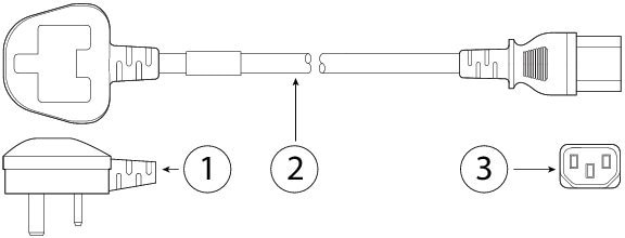
|
1 |
Plug: BS1363A/SS145 |
2 |
Cord set rating: 10A, 250V |
|
3 |
Connector: IEC 60320-C13 |
|
1 |
Plug: NEMA5-15P/JIS 8303 |
2 |
Cord set rating: 12A, 125V |
|
3 |
Connector: IEC 60320-C15 |
|
1 |
Plug: NEMA L6-20P |
2 |
Cord set rating: 15A, 250V |
|
3 |
Connector: IEC 60320-C13 |
|
1 |
Plug: SABS 164 |
2 |
Cord set rating: 10A, 250V |
|
3 |
Connector: IEC 60320-C15 |
|
1 |
Plug: CCC GB2099.1, GB1002 |
2 |
Cord set rating: 10A, 250V |
|
3 |
Connector: IEC 60320-C15 |
|
1 |
Plug: IS 6538-1971 |
2 |
Cord set rating: 10A, 250V |
|
3 |
Connector: IEC 60320-C13 |
|
1 |
Plug: NBR 14136 |
2 |
Cord set rating: 10A, 250V |
|
3 |
Connector: IEC 60320-C13 |
|
1 |
Plug: CNS10917-2 |
2 |
Cord set rating: 10A, 125V |
|
3 |
Connector: IEC 60320-C15 |
|
1 |
Plug: SI-32 |
2 |
Cord set rating: 10A, 250V |
|
3 |
Connector: IEC 60320-C13 |
|
1 |
Plug: IEC 60884-1 |
2 |
Cord set rating: 10A, 250V |
|
3 |
Connector: IEC 60320-C13 |
|
1 |
Plug: BS1363A/SS145 |
2 |
Cord set rating: 10A, 250V |
|
3 |
Connector: IEC 60320-C13 |
Hardware Specifications
The following table contains hardware specifications for the Firepower 4100 series security appliance.
 反馈
反馈