Cisco Firepower 4110、4120、4140 和 4150 硬件安装指南
非歧视性语言
此产品的文档集力求使用非歧视性语言。在本文档集中,非歧视性语言是指不隐含针对年龄、残障、性别、种族身份、族群身份、性取向、社会经济地位和交叉性的歧视的语言。由于产品软件的用户界面中使用的硬编码语言、基于 RFP 文档使用的语言或引用的第三方产品使用的语言,文档中可能无法确保完全使用非歧视性语言。 深入了解思科如何使用包容性语言。
当地语言翻译版本说明
思科可能会在某些地方提供本内容的当地语言翻译版本。请注意,翻译版本仅供参考,如有任何不一致之处,以本内容的英文版本为准。
- 已更新:
- 2021年2月12日
Chapter: Mount and Connect
Mount and
Connect
This chapter describes how to rack-mount the Cisco Firepower 4100 security appliance, how to ground it, and how to connect the cords and cables. It contains the following sections:
- Rack-Mount the Chassis
- Ground the Chassis
- Install the FIPS Opacity Shield
- Connect Cables, Turn on Power, and Verify Connectivity
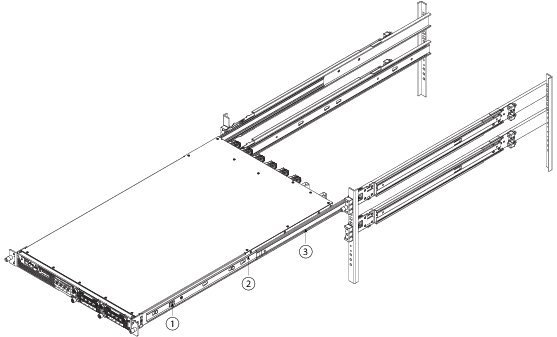
Rack-Mount the Chassis
Take note of the following warnings:
 警告 | Statement 1018—Supply Circuit Take care when connecting units to the supply circuit so that wiring is not overloaded. |
警告 | Statement 1032—Lifting the Chassis To prevent personal injury or damage to the chassis, never attempt to lift or tilt the chassis using the handles on modules (such as power supplies, fans, or cards); these types of handles are not designed to support the weight of the unit. |
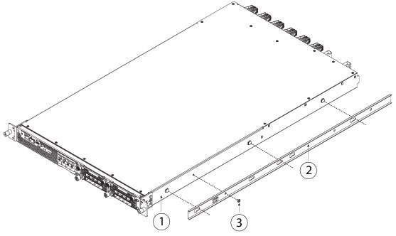
This procedure describes how to install the Firepower 4100 in a rack using the rack kit from the accessory kit that shipped with the chassis.
You need the following to install the Firepower 4100 in a rack (4-post EIA-310-D rack):
-
#1 Phillips Head screwdriver
-
Firepower 4100 accessory kit that contains the slide rails, mounting ears, and screws
Slide rail assemblies work with four-post racks and cabinets with square slots, round 7.1mm holes and 10-32 threaded holes on the rack post front. The slide rail works with front to back spacing of rack posts from 24 to 36 inches.
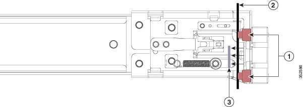
 注 | Internal obstructions between rails can make slide rail installation more complicated. Use racks that do not have internal obstructions between rails for unhindered slide rail installation. |
接下来的操作
Continue with Connect Cables, Turn on Power, and Verify Connectivity.
Ground the Chassis
警告 | Statement 1024—Ground Conductor This equipment must be grounded. Never defeat the ground conductor or operate the equipment in the absence of a suitably installed ground conductor. Contact the appropriate electrical inspection authority or an electrician if you are uncertain that suitable grounding is available. |
警告 | Statement 1046—Installing or Replacing the Unit When installing or replacing the unit, the ground connection must always be made first and disconnected last. |
警告 | Statement 1025—Use Copper Conductors Only Use copper conductors only. |
 小心 | Grounding the chassis is required, even if the rack is already grounded. A grounding pad with two threaded M4 holes is provided on the chassis for attaching a grounding lug. The ground lug must be NRTL-listed. In addition, a copper conductor (wires) must be used and the copper conductor must comply with NEC code for ampacity. |
| 步骤 1 | Use a wire-stripping tool to remove approximately 0.75 inches (19 mm) of the covering from the end of the grounding cable. |
| 步骤 2 | Insert the stripped end of the grounding cable into the open end of the grounding lug. |
| 步骤 3 | Use the crimping tool to secure the grounding cable in the grounding lug. |
| 步骤 4 | Remove the adhesive label from the grounding pad on the chassis. |
| 步骤 5 | Place the grounding lug against the grounding pad so that there is solid metal-to-metal contact, and insert the two M4 screws with washers through the holes in the grounding lug and into the grounding pad. |
| 步骤 6 | Make sure that the lug and cable do not interfere with other equipment. |
| 步骤 7 | Prepare the other end of the grounding cable and connect it to an appropriate grounding point in your site to ensure adequate earth ground. |
Install the FIPS Opacity Shield
小心 | This procedure should be performed only by the Crypto Officer. |
注 | Because the FIPS opacity shield covers the serial number on the chassis, you need to copy the serial number on a label and attach it to the chassis where it can be retrieved or viewed easily before you install the FIPS opacity shield. You need the serial number when you call Cisco TAC. |
You need the following to install the FIPS opacity shield:
-
#1 Phillips head screwdriver
-
The following items from the FIPS kit:
-
One FIPS opacity shield
-
Four 8-32 x .375" countersink screws used to secure the FIPS opacity shield to the cable management brackets
-
15 tamper-evident labels (TELs)
-
-
The following items from the Firepower 4100 accessory kit:
-
Two cable management brackets
-
Four 8-32 x .375" countersink screws used to secure the cable management brackets to the slide rail locking brackets
-
| 步骤 1 | Copy the serial number on a label and attach it to the chassis where it can be retrieved easily for future use if needed. To find the serial number, see Serial Number Location. | ||||||||||
| 步骤 2 | Pull the chassis out of the rack until the release latches catch. | ||||||||||
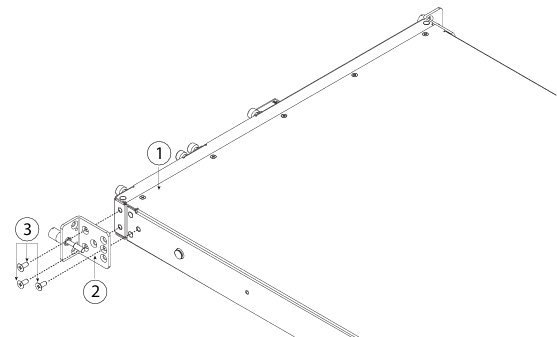
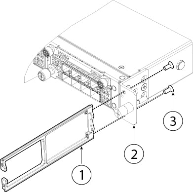
| 步骤 3 | If you have not already done so, attach a slide rail locking bracket to each side of the chassis using the six 8-32 x .375" countersink Phillips head screws provided in the accessory kit.
| ||||||||||
| 步骤 4 | Attach a cable management bracket to each slide rail locking bracket using the four 8-32 x .375" countersink Phillips head screws provided in the accessory kit.
| ||||||||||
| 步骤 5 | Connect the cables to the ports. See Connect Cables, Turn on Power, and Verify Connectivity for the procedure.
If you are installing the FIPS opacity shield after the initial product installtion, the cables will already be connected. If the attached cables do not have enough slack to route them through the cable mounting brackets (as shown below), you will have to turn the power off on the Firepower 4100, remove the cables, route the cables through the cable mounting brackets, reattach the cables, and continue with step 7 below.
If you are installing the FIPS opacity shield after the initial product installation, the cables are already connected. If the attached cables do not have enough slack to route them through the cable mounting brackets (as shown below), power down the appliance, remove the cables, route the cables through the cable mounting brackets, reattach the cables, and continue with step 7 below. | ||||||||||
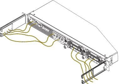
| 步骤 6 | Route the cables through the openings in the cable management brackets.
 | ||||||||||
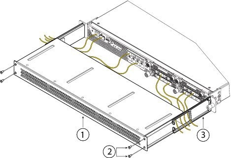
| 步骤 7 | Attach the FIPS opacity shield to the cable management brackets using the four 8-32 x .375" countersink Phillips head screws provided in the FIPS kit.
| ||||||||||
| 步骤 8 | Attach the 15 TELs. For information on the procedure and correct placement of the TELs, see the Tamper Evidence Label (TEL) Placement section (section 2.13 ) in the FIPS 140-2 Non Proprietary Security Policy Level 2 Validation document. | ||||||||||
| 步骤 9 | Attach the power cable to the appliance and connect it to an electrical outlet. | ||||||||||
| 步骤 10 | Press the power switch on the rear panel. | ||||||||||
| 步骤 11 | Check the power LED on the front panel. See Front Panel LEDs for a description of the power LED. Solid green indicates that the appliance is powered on.
| ||||||||||
| 步骤 12 | See the quick start guide for your operating software for further configuration information: |
Connect Cables, Turn on Power, and Verify Connectivity
Take note of the following warnings:
警告 | Statement 1021—SELV Circuit To avoid electric shock, do not connect safety extra-low voltage (SELV) circuits to telephone-network voltage (TNV) circuits. LAN ports contain SELV circuits, and WAN ports contain TNV circuits. Some LAN and WAN ports both use RJ-45 connectors. Use caution when connecting cables. |
警告 | Statement 1051—Laser Radiation Invisible laser radiation may be emitted from disconnected fibers or connectors. Do not stare into beams or view directly with optical instruments. |
警告 | Statement 1053—Class 1M Laser Radiation Class 1M laser radiation when open. Do not view directly with optical instruments. |
警告 | Statement 1055—Class I and Class 1M Laser Class I (CDRH) and Class 1M (IEC) laser products. |
After rack mounting the Firepower 4100 series security appliance, follow these steps to connect cables, turn on power, and verify connectivity.
| 步骤 1 | Connect the
console port.
Using a serial console cable, connect a computer or terminal server to the RJ-45 serial console port (baud rate is 9600) so that you can use the CLI to initially set up the Firepower 4100. | ||||||||
| 步骤 2 | Connect the
management interface.
Install the 1 Gigabit Ethernet transceiver that was provided in the Firepower 4100 accessory kit in the Management port, and then using an Ethernet cable, connect a management computer directly to the transceiver. 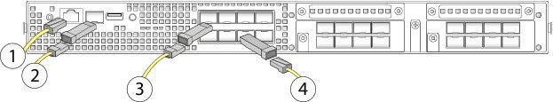
| ||||||||
| 步骤 3 | Install the
SFP/SFP+ transceivers.
Install SFP/SFP+/ transceivers in the Ethernet network interfaces in the fixed ports or in the network modules you have installed taking care not to touch the contacts in the rear. Flip the SFP+ over to connect in the upper ports. The SFP+ connects in the normal way in the lower ports. The sockets on the upper row face up and the sockets on the lower row face down.
| ||||||||
| 步骤 4 | Connect the
Ethernet interfaces.
Use the proper cable to connect the SFP/SFP+ transceivers in the fixed ports or in the network modules you have installed. | ||||||||
| 步骤 5 | (Optional) If you are installing the FIPS opacity shield, continue with step 6 in Install the FIPS Opacity Shield. | ||||||||
| 步骤 6 | Attach the power cable to the appliance and connect it to an electrical outlet. | ||||||||
| 步骤 7 | Press the power switch on the rear panel. | ||||||||
| 步骤 8 | Check the power
LED on the front panel. Solid green indicates that the appliance is powered on.
| ||||||||
| 步骤 9 | See the quick start guide for your operating software for further configuration information: |
 反馈
反馈