简介
本文档介绍如何了解桥接虚拟接口(BVI)和桥接域接口(BDI)并对其进行故障排除。
先决条件
要求
对本文没有要求。
使用的组件
本文档中的信息基于 ISR 路由器(对应于 BVI)和 ASR1K(对应于 BDI)。
本文档中的信息都是基于特定实验室环境中的设备编写的。本文档中使用的所有设备最初均采用原始(默认)配置。如果您的网络处于活动状态,请确保您了解所有命令的潜在影响。
背景信息
BVI和BDI路由接口代表一组桥接的接口。例如,您希望桥接路由器上的两个接口,并且希望它们位于同一第2层广播域中。BVI/BDI接口将充当这两个桥接物理接口的路由接口。所有数据包流量都必须通过BVI/BDI接口。
 2台PC到路由器的BVI连接
Cisco IOS®上的BVI
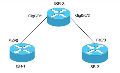
路由器不会在同一广播域中配置两个或多个第3层接口(即同一子网中的两个或多个接口)。 使用BVI接口将两台PC连接到路由器作为同一子网的一部分,并且仍然可以从这两台PC访问Internet。
您可以使用BVI执行此操作。
|
期限
|
定义
|
|
Bridge-group
|
将多个物理接口划分到一个逻辑组.
|
|
接口 BVI
|
可以路由的逻辑接口的第3层。
|
|
ISR 3
|
ISR 1
|
ISR 2
|
|
bridge irb
bridge 1 protocol ieee
bridge 1 route ip
!
interface GigabitEthernet0/0/1
bridge-group 1
!
interface GigabitEthernet0/0/2
bridge-group 1
!
interface BVI 1
ip address 10.10.10.10
255.255.255.0
|
int fa0/0
ip address 10.10.10.1
255.255.255.0
|
int fa0/0
ip address 10.10.10.2
255.255.255.0
|
Cisco IOS XE上的BDI
BDI与BVI类似,不同之处在于它运行在Cisco IOS XE上。
|
期限
|
定义
|
|
网桥域
|
表示第2层广播域。
|
|
网桥域接口
|
是允许第2层桥接网络和第3层路由网络之间双向流量传输的逻辑接口。
|
|
以太网虚拟电路(EVC)
|
是由提供商提供给客户的第2层服务的单个实例的端到端表示。在思科 EVC 框架中,网桥域由一个或多个称为服务实例的第 2 层接口组成。服务实例是给定路由器上给定端口上的 EVC 实例化。服务实例基于配置与网桥域关联。
|
 两台交换机上的ASR连接
Cisco IOS XE平台上的BDI示例
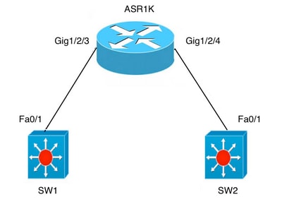
A) 两台交换机上的 Fa0/1 都是第 3 层接口,并位于同一个广播域中。
如果目的只是建立两台交换机之间的连接,则不需要在ASR上进行BDI配置。
|
ASR 1K
|
SW1
|
SW2
|
|
interface GigabitEthernet1/2/3
no ip address
negotiation auto
cdp enable
service instance 100 ethernet
encapsulation untag
bridge-domain 100
!
interface GigabitEthernet1/2/4
no ip address
negotiation auto
cdp enable
service instance 100 ethernet
encapsulation untag
bridge-domain 100
|
interface FastEthernet0/1
no switchport
ip address 10.1.1.1 255.255.255.0
|
interface FastEthernet0/1
no switchport
ip address 10.1.1.3 255.255.255.0
|
后续步骤
1.从SW1 ping SW2:
BGL.Q.16-3500-1#ping 10.1.1.3
2.键入要中止的转义序列。
Sending 5, 100-byte ICMP Echos to 10.1.1.3, timeout is 2 seconds:

!!!!!

Success rate is 100 percent (5/5), round-trip min/avg/max = 1/4/9 ms
注意:如果要在ASR外部路由,则需要配置BDI接口:
interface BDI100

ip address 10.1.1.1 255.255.255.0
B)桥接两台交换机之间的多个VLAN。
在物理接口下为每个 VLAN 配置单独的以太网虚拟电路 (EVC)。不支持在子接口下使用网桥域。
有两个VLAN:要桥接的VLAN 100和VLAN 200:
|
ASR 1K
|
SW1
|
SW2
|
|
interface GigabitEthernet1/2/3
no ip address
negotiation auto
cdp enable
service instance 100 ethernet
encapsulation dot1q 100
rewrite ingress tag pop 1 symmetric
bridge-domain 100
!
service instance 200 ethernet
encapsulation dot1q 200
rewrite ingress tag pop 1 symmetric
bridge-domain 200
Exact same config under Gig1/2/4
interface GigabitEthernet1/2/4
no ip address
negotiation auto
cdp enable
service instance 100 ethernet
encapsulation dot1q 100
rewrite ingress tag pop 1 symmetric
bridge-domain 100
!
service instance 200 ethernet
encapsulation dot1q 200
rewrite ingress tag pop 1 symmetric
bridge-domain 200
|
interface FastEthernet0/1
switchport trunk encapsulation dot1q
switchport mode trunk
interface Vlan100
ip address 10.1.1.1 255.255.255.0
interface Vlan200
ip address 10.1.1.2 255.255.255.0
|
interface FastEthernet0/1
switchport trunk encapsulation dot1q
switchport mode trunk
interface Vlan100
ip address 10.1.1.3 255.255.255.0
interface Vlan200
ip address 10.1.1.2 255.255.255.0
|
后续步骤
1.从SW1 ping SW2上的int vlan100和vlan200:
BGL.Q.16-3500-1#ping 10.1.1.3
2.键入要中止的转义序列:
Sending 5, 100-byte ICMP Echos to 10.1.1.3, timeout is 2 seconds:

!!!!!

Success rate is 100 percent (5/5), round-trip min/avg/max = 1/4/9 ms

BGL.Q.16-3500-1#ping 10.1.1.3
3.键入要中止的转义序列:
Sending 5, 100-byte ICMP Echos to 10.1.1.3, timeout is 2 seconds:

!!!!!

Success rate is 100 percent (5/5), round-trip min/avg/max = 1/2/9 ms
EPC
monitor capture CAP interface gig1/2/3 efp 100 both match ipv4 any any
packet tracer
debug platform condition interface gig1/2/3 efp-id 100 ipv4 both

EFP ID = 100 (service instance number)
相关信息
 反馈
反馈