Anuncie sub-redes VPN de acesso remoto através de protocolos de roteamento no FTD
Opções de download
Linguagem imparcial
O conjunto de documentação deste produto faz o possível para usar uma linguagem imparcial. Para os fins deste conjunto de documentação, a imparcialidade é definida como uma linguagem que não implica em discriminação baseada em idade, deficiência, gênero, identidade racial, identidade étnica, orientação sexual, status socioeconômico e interseccionalidade. Pode haver exceções na documentação devido à linguagem codificada nas interfaces de usuário do software do produto, linguagem usada com base na documentação de RFP ou linguagem usada por um produto de terceiros referenciado. Saiba mais sobre como a Cisco está usando a linguagem inclusiva.
Sobre esta tradução
A Cisco traduziu este documento com a ajuda de tecnologias de tradução automática e humana para oferecer conteúdo de suporte aos seus usuários no seu próprio idioma, independentemente da localização. Observe que mesmo a melhor tradução automática não será tão precisa quanto as realizadas por um tradutor profissional. A Cisco Systems, Inc. não se responsabiliza pela precisão destas traduções e recomenda que o documento original em inglês (link fornecido) seja sempre consultado.
Contents
Introdução
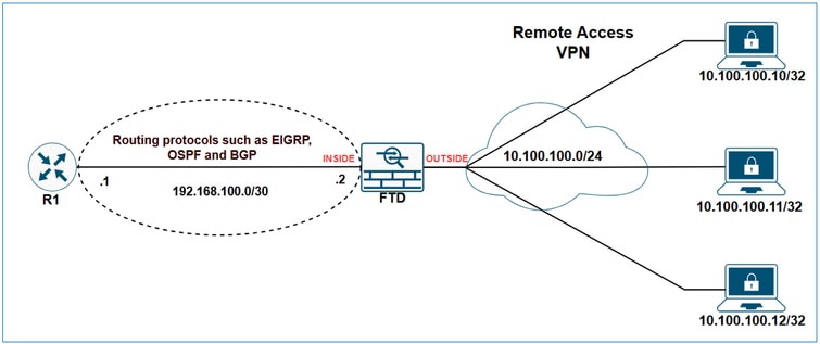
Este documento descreve as opções disponíveis para anunciar sub-redes relacionadas a VPN usando os protocolos de roteamento EIGRP, OSPF e BGP.
Pré-requisitos
Requisitos
Não existem requisitos específicos para este documento.
Componentes Utilizados
As informações neste documento foram criadas a partir de dispositivos em um ambiente de laboratório específico. Todos os dispositivos utilizados neste documento foram iniciados com uma configuração (padrão) inicial. Se a rede estiver ativa, certifique-se de que você entenda o impacto potencial de qualquer comando.
As informações neste documento são baseadas nestas versões de software e hardware:
- Cisco Secure Firewall Management Center 7.6.0
- Cisco Secure Firewall 7.6.0
Note: Este documento descreve a configuração para a redistribuição de sub-redes VPN de Acesso Remoto através de EIGRP, OSPF e BGP usando o FMC. Para obter orientação sobre a redistribuição de rota com o FDM, consulte o guia de configuração do FDM.
Informações de Apoio
A primeira coisa a entender é como o FTD classifica as sub-redes VPN em sua tabela de roteamento. Embora essas sub-redes apareçam como conectadas por VPN, elas não são consideradas sub-redes diretamente conectadas; em vez disso, são tratadas como rotas estáticas.
As saídas de show demonstram isso.
Saída de show route de FTD:
FTD-1# show route

Codes: L - local, C - connected, S - static, R - RIP, M - mobile, B - BGP
       D - EIGRP, EX - EIGRP external, O - OSPF, IA - OSPF inter area
       N1 - OSPF NSSA external type 1, N2 - OSPF NSSA external type 2
       E1 - OSPF external type 1, E2 - OSPF external type 2, V - VPN
       i - IS-IS, su - IS-IS summary, L1 - IS-IS level-1, L2 - IS-IS level-2
       ia - IS-IS inter area, * - candidate default, U - per-user static route
       o - ODR, P - periodic downloaded static route, + - replicated route
       SI - Static InterVRF, BI - BGP InterVRF
Gateway of last resort is not set

C        10.10.20.0 255.255.255.0 is directly connected, outside
L        10.10.20.1 255.255.255.255 is directly connected, outside
C        192.168.100.0 255.255.255.252 is directly connected, inside
L        192.168.100.2 255.255.255.255 is directly connected, inside
V        10.100.100.10 255.255.255.255 connected by VPN (advertised), outside
Saída de FTD show route connected:
FTD-1# show route connected

Codes: L - local, C - connected, S - static, R - RIP, M - mobile, B - BGP
       D - EIGRP, EX - EIGRP external, O - OSPF, IA - OSPF inter area
       N1 - OSPF NSSA external type 1, N2 - OSPF NSSA external type 2
       E1 - OSPF external type 1, E2 - OSPF external type 2, V - VPN
       i - IS-IS, su - IS-IS summary, L1 - IS-IS level-1, L2 - IS-IS level-2
       ia - IS-IS inter area, * - candidate default, U - per-user static route
       o - ODR, P - periodic downloaded static route, + - replicated route
       SI - Static InterVRF, BI - BGP InterVRF

Gateway of last resort is not set

C        10.10.20.0 255.255.255.0 is directly connected, outside
L        10.10.20.1 255.255.255.255 is directly connected, outside
C        192.168.100.0 255.255.255.252 is directly connected, inside
L        192.168.100.2 255.255.255.255 is directly connected, inside
Saída FTD show route static:
FTD-HQ-1# show route static

Codes: L - local, C - connected, S - static, R - RIP, M - mobile, B - BGP
       D - EIGRP, EX - EIGRP external, O - OSPF, IA - OSPF inter area
       N1 - OSPF NSSA external type 1, N2 - OSPF NSSA external type 2
       E1 - OSPF external type 1, E2 - OSPF external type 2, V - VPN
       i - IS-IS, su - IS-IS summary, L1 - IS-IS level-1, L2 - IS-IS level-2
       ia - IS-IS inter area, * - candidate default, U - per-user static route
       o - ODR, P - periodic downloaded static route, + - replicated route
       SI - Static InterVRF, BI - BGP InterVRF

Gateway of last resort is not set

V        10.100.100.10 255.255.255.255 connected by VPN (advertised), outside
Agora que está claro como as sub-redes VPN são tratadas na tabela de roteamento do firewall, a próxima etapa é explorar como anunciá-las usando vários protocolos de roteamento.
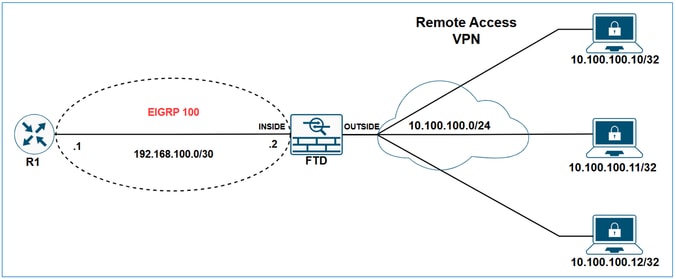
Redistribuir Sub-redes VPN de Acesso Remoto por EIGRP em FTD
Diagrama de Rede
As rotas estáticas que estão dentro do escopo de uma instrução de rede são automaticamente redistribuídas para o EIGRP; você não precisa definir uma regra de redistribuição para eles. No entanto, ao redistribuir rotas estáticas que apontam para interfaces VTI no EIGRP, você deve especificar a métrica. Para rotas estáticas que apontam para outros tipos de interfaces, não é necessário especificar a métrica.
Devido ao comportamento do EIGRP de redistribuir automaticamente as rotas estáticas que caem dentro do escopo das instruções de rede, há duas opções para anunciar sub-redes VPN via EIGRP no FTD:
- Usando uma instrução de rede.
- Usando a abordagem redistribuir estática.
Neste exemplo, o objetivo é fazer com que R1 aprenda a sub-rede VPN 10.100.100.0/24 através do EIGRP.
Configuração inicial do FTD:
hostname FTD-1
!
ip local pool VPN-POOL1 10.100.100.10-10.100.100.254 mask 255.255.255.0
!
webvpn
...
  group-policy LAB_GROUP1 internal
group-policy LAB_GROUP1 attributes
...
  address-pools value VPN-POOL1
!
router eigrp 100
 no default-information in
 no default-information out
 no eigrp log-neighbor-warnings
 no eigrp log-neighbor-changes
network 192.168.100.0 255.255.255.252
Tabela de roteamento inicial de FTD:
FTD-1# show route

Codes: L - local, C - connected, S - static, R - RIP, M - mobile, B - BGP
       D - EIGRP, EX - EIGRP external, O - OSPF, IA - OSPF inter area
       N1 - OSPF NSSA external type 1, N2 - OSPF NSSA external type 2
       E1 - OSPF external type 1, E2 - OSPF external type 2, V - VPN
       i - IS-IS, su - IS-IS summary, L1 - IS-IS level-1, L2 - IS-IS level-2
       ia - IS-IS inter area, * - candidate default, U - per-user static route
       o - ODR, P - periodic downloaded static route, + - replicated route
       SI - Static InterVRF, BI - BGP InterVRF

Gateway of last resort is not set

C        10.10.20.0 255.255.255.0 is directly connected, outside
L        10.10.20.1 255.255.255.255 is directly connected, outside
C        192.168.100.0 255.255.255.252 is directly connected, inside
L        192.168.100.2 255.255.255.255 is directly connected, inside
V       10.100.100.10 255.255.255.255 connected by VPN (advertised), outside
Tabela de topologia EIGRP inicial de FTD:
FTD-1# show eigrp topology

EIGRP-IPv4 Topology Table for AS(100)/ID(192.168.100.2)
Codes: P - Passive, A - Active, U - Update, Q - Query, R - Reply,
       r - reply Status, s - sia Status

P 192.168.100.0 255.255.255.252, 1 successors, FD is 512 via Connected, inside
Tabela de roteamento inicial do R1:
R1#show ip route

Codes: L - local, C - connected, S - static, R - RIP, M - mobile, B - BGP
       D - EIGRP, EX - EIGRP external, O - OSPF, IA - OSPF inter area
       N1 - OSPF NSSA external type 1, N2 - OSPF NSSA external type 2
       E1 - OSPF external type 1, E2 - OSPF external type 2, m - OMP
       n - NAT, Ni - NAT inside, No - NAT outside, Nd - NAT DIA
       i - IS-IS, su - IS-IS summary, L1 - IS-IS level-1, L2 - IS-IS level-2
       ia - IS-IS inter area, * - candidate default, U - per-user static route
       H - NHRP, G - NHRP registered, g - NHRP registration summary
       o - ODR, P - periodic downloaded static route, l - LISP
       a - application route
       + - replicated route, % - next hop override, p - overrides from PfR
       & - replicated local route overrides by connected

Gateway of last resort is not set

C        192.168.100.0/30 is directly connected, GigabitEthernet1
L        192.168.100.1/32 is directly connected, GigabitEthernet1
Redistribuir Sub-redes VPN de Acesso Remoto por meio do EIGRP no FTD usando o comando network
Configurar
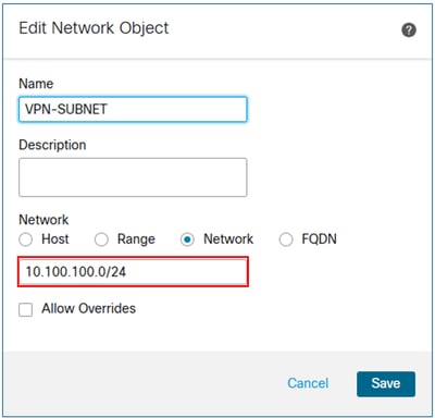
Etapa 1. Criar um objeto de rede para a sub-rede VPN.
Etapa 2. Incluir o objeto de sub-rede VPN na instrução network.
Na interface de usuário de gerenciamento de dispositivos do FMC, navegue para Routing > EIGRP > Setup e inclua a sub-rede VPN nas redes/hosts selecionados.
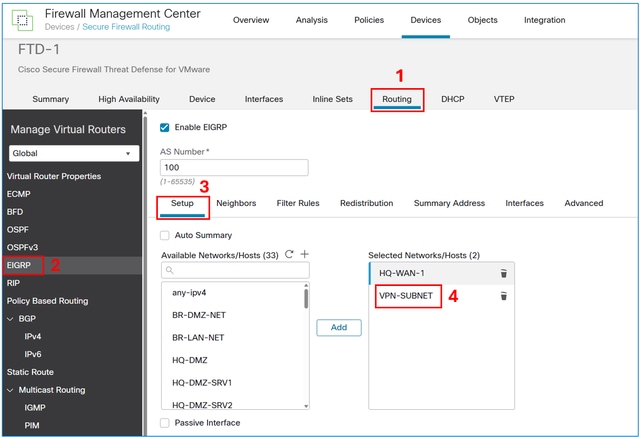
Salve e implante a configuração no FTD.
Verificar
Configuração do EIGRP de FTD:
FTD-1# show run router
router eigrp 100
 no default-information in
 no default-information out
 no eigrp log-neighbor-warnings
 no eigrp log-neighbor-changes
 network 10.100.100.0 255.255.255.0
 network 192.168.100.0 255.255.255.252
Tabela de topologia EIGRP de FTD:
FTD-1# show eigrp topology

EIGRP-IPv4 Topology Table for AS(100)/ID(192.168.100.2)
Codes: P - Passive, A - Active, U - Update, Q - Query, R - Reply,
       r - reply Status, s - sia Status

P 10.100.100.10 255.255.255.255, 1 successors, FD is 512
        via Rstatic (512/0)

P 192.168.100.0 255.255.255.252, 1 successors, FD is 512
        via Connected, inside
Tabela de roteamento de R1:
R1#show ip route

Codes: L - local, C - connected, S - static, R - RIP, M - mobile, B - BGP
       D - EIGRP, EX - EIGRP external, O - OSPF, IA - OSPF inter area
       N1 - OSPF NSSA external type 1, N2 - OSPF NSSA external type 2
       E1 - OSPF external type 1, E2 - OSPF external type 2, m - OMP
       n - NAT, Ni - NAT inside, No - NAT outside, Nd - NAT DIA
       i - IS-IS, su - IS-IS summary, L1 - IS-IS level-1, L2 - IS-IS level-2
       ia - IS-IS inter area, * - candidate default, U - per-user static route
       H - NHRP, G - NHRP registered, g - NHRP registration summary
       o - ODR, P - periodic downloaded static route, l - LISP
       a - application route
       + - replicated route, % - next hop override, p - overrides from PfR
       & - replicated local route overrides by connected


Gateway of last resort is not set

C        192.168.100.0/30 is directly connected, GigabitEthernet1
L        192.168.100.1/32 is directly connected, GigabitEthernet1
      10.0.0.0/32 is subnetted, 1 subnets
D        10.100.100.10
           [90/3072] via 192.168.100.2, 00:02:17, GigabitEthernet1
Note: Observe que, embora a instrução de rede fosse 10.100.100.0/24, o FTD redistribui uma sub-rede /32 pelo EIGRP. Isso ocorre porque o FTD cria uma rota estática com um prefixo /32 para cada sessão de VPN de acesso remoto. Para otimizar isso, você pode usar o recurso Endereço de Sumarização EIGRP.
Redistribuir Sub-redes VPN de Acesso Remoto por EIGRP em FTD usando a abordagem estática de redistribuição
Configurar
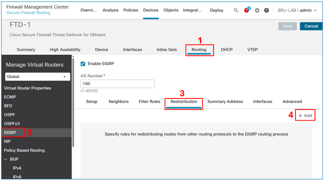
Na interface de usuário de gerenciamento de dispositivo FMC, navegue para Routing > EIGRP > Redistribution e selecione o botão Add.
No campo do protocolo, selecione Static e, em seguida, selecione o botão OK.
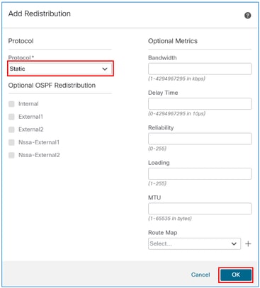
Cuidado: Isso redistribui todas as rotas estáticas no EIGRP. Se você precisar anunciar apenas as sub-redes VPN, poderá usar a abordagem de instrução de rede ou aplicar um mapa de rotas para filtrá-las.
O resultado:
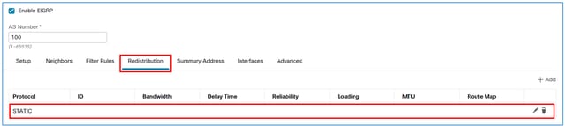
Salve e implante a configuração no FTD.
Verificar
Configuração do EIGRP de FTD:
FTD-HQ-1# show run router

router eigrp 100
 no default-information in
 no default-information out
 no eigrp log-neighbor-warnings
 no eigrp log-neighbor-changes
 network 192.168.100.0 255.255.255.252
 redistribute static
Tabela de topologia EIGRP de FTD:
FTD-1# show eigrp topology
EIGRP-IPv4 Topology Table for AS(100)/ID(192.168.100.2)
Codes: P - Passive, A - Active, U - Update, Q - Query, R - Reply,
       r - reply Status, s - sia Status

P 10.100.100.10 255.255.255.255, 1 successors, FD is 512
        via Rstatic (512/0)
P 192.168.100.0 255.255.255.252, 1 successors, FD is 512
        via Connected, inside
Tabela de roteamento de R1:
R1#show ip route

Codes: L - local, C - connected, S - static, R - RIP, M - mobile, B - BGP
       D - EIGRP, EX - EIGRP external, O - OSPF, IA - OSPF inter area
       N1 - OSPF NSSA external type 1, N2 - OSPF NSSA external type 2
       E1 - OSPF external type 1, E2 - OSPF external type 2, m - OMP
       n - NAT, Ni - NAT inside, No - NAT outside, Nd - NAT DIA
       i - IS-IS, su - IS-IS summary, L1 - IS-IS level-1, L2 - IS-IS level-2
       ia - IS-IS inter area, * - candidate default, U - per-user static route
       H - NHRP, G - NHRP registered, g - NHRP registration summary
       o - ODR, P - periodic downloaded static route, l - LISP
       a - application route
       + - replicated route, % - next hop override, p - overrides from PfR
       & - replicated local route overrides by connected

Gateway of last resort is not set

C        192.168.100.0/30 is directly connected, GigabitEthernet1
L        192.168.100.1/32 is directly connected, GigabitEthernet1
D EX     10.100.100.10
           [170/3072] via 192.168.100.2, 00:03:52, GigabitEthernet1
Tip: Opcionalmente, você pode usar o recurso de endereço de sumarização EIGRP no FTD para otimizar o tamanho da tabela de roteamento.
Configuração do Endereço de Resumo do EIGRP
Configurar
Se ainda não tiver sido criado, crie um objeto de rede para as sub-redes VPN.

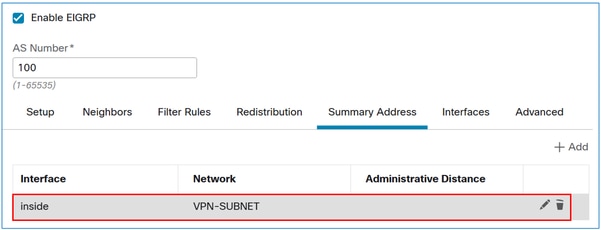
Na interface de usuário de gerenciamento de dispositivo FMC, navegue para Routing > EIGRP > Summary Address e selecione o botão Add.
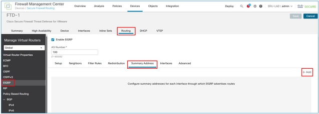
No campo interface, insira aquele voltado para o vizinho EIGRP e, no campo network, insira o objeto criado para a sub-rede VPN.
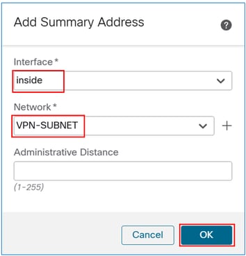
O resultado:
Verificar
Configuração do Endereço Resumido EIGRP de FTD:
FTD-1# sh run interface

interface GigabitEthernet0/0
 nameif inside
 security-level 0
 zone-member inside
 ip address 192.168.100.2 255.255.255.252
summary-address eigrp 100 10.100.100.0 255.255.255.0
Tabela de topologia EIGRP de FTD:
FTD-1# show eigrp topology

EIGRP-IPv4 Topology Table for AS(100)/ID(192.168.100.2)
Codes: P - Passive, A - Active, U - Update, Q - Query, R - Reply,
       r - reply Status, s - sia Status

P 10.100.100.10 255.255.255.255, 1 successors, FD is 512
        via Rstatic (512/0)
P 10.100.100.0 255.255.255.0, 1 successors, FD is 512
        via Summary (512/0), Null0
P 192.168.100.0 255.255.255.0, 1 successors, FD is 512
        via Connected, inside
Tabela de roteamento de R1:
R1#show ip route

Codes: L - local, C - connected, S - static, R - RIP, M - mobile, B - BGP
       D - EIGRP, EX - EIGRP external, O - OSPF, IA - OSPF inter area
       N1 - OSPF NSSA external type 1, N2 - OSPF NSSA external type 2
       E1 - OSPF external type 1, E2 - OSPF external type 2, m - OMP
       n - NAT, Ni - NAT inside, No - NAT outside, Nd - NAT DIA
       i - IS-IS, su - IS-IS summary, L1 - IS-IS level-1, L2 - IS-IS level-2
       ia - IS-IS inter area, * - candidate default, U - per-user static route
       H - NHRP, G - NHRP registered, g - NHRP registration summary
       o - ODR, P - periodic downloaded static route, l - LISP
       a - application route
       + - replicated route, % - next hop override, p - overrides from PfR
       & - replicated local route overrides by connected

Gateway of last resort is not set

C        192.168.100.0/30 is directly connected, GigabitEthernet1
L        192.168.100.1/32 is directly connected, GigabitEthernet1
      10.0.0.0/24 is subnetted, 1 subnets
D        10.100.100.0 [90/3072] via 192.168.100.2, 00:01:54, GigabitEthernet1
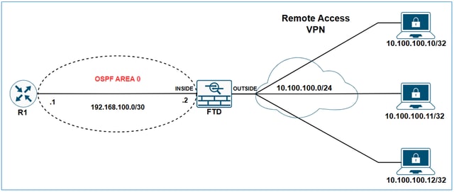
Redistribuir Sub-redes VPN de Acesso Remoto através do OSPF no FTD
Diagrama de Rede
Configurações iniciais
ip local pool VPN-POOL1 10.100.100.10-10.100.100.254 mask 255.255.255.0
!
webvpn
  group-policy LAB_GROUP1 internal
...
group-policy LAB_GROUP1 attributes
...
  address-pools value VPN-POOL1
!
router ospf 1
network 192.168.100.0 255.255.255.252 area 0
Saída do FTD show ospf neighbor:
FTD-1# show ospf neighbor

Neighbor ID     Pri   State           Dead Time   Address         Interface
192.168.100.1          1   FULL/DR         0:00:39     192.168.100.1   inside
Saída de show ip ospf neighbor de R1:
R1#show ip ospf neighbor

Neighbor ID     Pri   State           Dead Time   Address         Interface
192.168.100.2    1   FULL/BDR        00:00:37    192.168.100.2  GigabitEthernet1
Tabela de roteamento de R1:
R1#show ip route

Codes: L - local, C - connected, S - static, R - RIP, M - mobile, B - BGP
       D - EIGRP, EX - EIGRP external, O - OSPF, IA - OSPF inter area
       N1 - OSPF NSSA external type 1, N2 - OSPF NSSA external type 2
       E1 - OSPF external type 1, E2 - OSPF external type 2, m - OMP
       n - NAT, Ni - NAT inside, No - NAT outside, Nd - NAT DIA
       i - IS-IS, su - IS-IS summary, L1 - IS-IS level-1, L2 - IS-IS level-2
       ia - IS-IS inter area, * - candidate default, U - per-user static route
       H - NHRP, G - NHRP registered, g - NHRP registration summary
       o - ODR, P - periodic downloaded static route, l - LISP
       a - application route
       + - replicated route, % - next hop override, p - overrides from PfR
       & - replicated local route overrides by connected

Gateway of last resort is not set

C        192.168.100.0/30 is directly connected, GigabitEthernet1
L        192.168.100.1/32 is directly connected, GigabitEthernet1
Configurar
Na interface de usuário de gerenciamento de dispositivos do FMC, navegue para Routing > OSPF > Redistribution e selecione o botão Add.
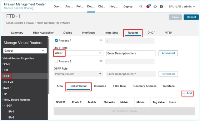
Note: A função OSPF deve ser definida como ASBR ou ABR e ASBR para habilitar a redistribuição.
No campo Tipo de rota, selecione Estático e marque a caixa Usar sub-redes.
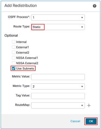
Cuidado: isso redistribui todas as rotas estáticas no OSPF. Se você precisar anunciar apenas as sub-redes VPN, poderá aplicar um mapa de rotas para filtrá-las.
O resultado:

Verificar
Configuração de redistribuição de OSPF FTD:
FTD-1# sh run router
router ospf 1
 network 192.168.100.0 255.255.255.252 area 0
 redistribute static subnets
Tabela de roteamento de R1:
R1#show ip route

Codes: L - local, C - connected, S - static, R - RIP, M - mobile, B - BGP
       D - EIGRP, EX - EIGRP external, O - OSPF, IA - OSPF inter area
       N1 - OSPF NSSA external type 1, N2 - OSPF NSSA external type 2
       E1 - OSPF external type 1, E2 - OSPF external type 2, m - OMP
       n - NAT, Ni - NAT inside, No - NAT outside, Nd - NAT DIA
       i - IS-IS, su - IS-IS summary, L1 - IS-IS level-1, L2 - IS-IS level-2
       ia - IS-IS inter area, * - candidate default, U - per-user static route
       H - NHRP, G - NHRP registered, g - NHRP registration summary
       o - ODR, P - periodic downloaded static route, l - LISP
       a - application route
       + - replicated route, % - next hop override, p - overrides from PfR
       & - replicated local route overrides by connected

Gateway of last resort is not set

C        192.168.100.0/30 is directly connected, GigabitEthernet1
L        192.168.100.1/32 is directly connected, GigabitEthernet1
      10.0.0.0/32 is subnetted, 1 subnets
O E2     10.100.100.10 [110/20] via 192.168.100.2, 00:08:01, GigabitEthernet1
Tip: Observe que, embora o pool de VPN seja 10.100.100.0/24, o FTD redistribui uma sub-rede /32 sobre OSPF. Isso ocorre porque o FTD cria uma rota estática com um prefixo /32 para cada sessão de VPN de acesso remoto. Para otimizar isso, você pode usar o recurso OSPF Summary Address.
Configuração do endereço de resumo do OSPF
Configurar
Se ainda não tiver sido criado, crie um objeto de rede para as sub-redes VPN.

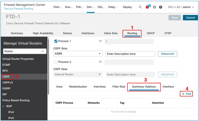
Na interface de usuário de gerenciamento de dispositivos do FMC, navegue para Routing > OSPF> Summary Address e selecione o botão Add.
Adicione o objeto de sub-rede VPN e marque a caixa de seleção Advertise.
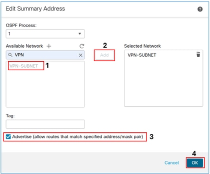
O resultado:
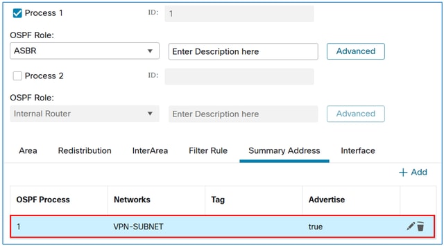
Verificar
Configuração do OSPF FTD:
FTD-1# sh run router

router ospf 1
 network 192.168.100.0 255.255.255.252 area 0
redistribute static subnets
 summary-address 10.100.100.0 255.255.255.0
Tabela de roteamento de R1:
R1#sh ip route

Codes: L - local, C - connected, S - static, R - RIP, M - mobile, B - BGP
       D - EIGRP, EX - EIGRP external, O - OSPF, IA - OSPF inter area
       N1 - OSPF NSSA external type 1, N2 - OSPF NSSA external type 2
       E1 - OSPF external type 1, E2 - OSPF external type 2, m - OMP
       n - NAT, Ni - NAT inside, No - NAT outside, Nd - NAT DIA
       i - IS-IS, su - IS-IS summary, L1 - IS-IS level-1, L2 - IS-IS level-2
       ia - IS-IS inter area, * - candidate default, U - per-user static route
       H - NHRP, G - NHRP registered, g - NHRP registration summary
       o - ODR, P - periodic downloaded static route, l - LISP
       a - application route
       + - replicated route, % - next hop override, p - overrides from PfR
       & - replicated local route overrides by connected

Gateway of last resort is not set

C        192.168.100.0/30 is directly connected, GigabitEthernet1
L        192.168.100.1/32 is directly connected, GigabitEthernet1
      10.0.0.0/24 is subnetted, 1 subnets
O E2     10.100.100.0 [110/20] via 192.168.100.2, 00:00:26, GigabitEthernet1
Redistribuir Sub-redes VPN de Acesso Remoto através do eBGP no FTD
Diagrama de Rede
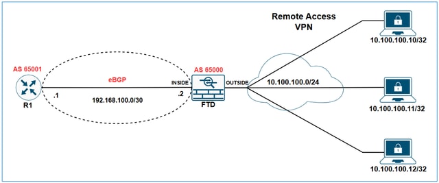
Neste exemplo, o objetivo é fazer com que R1 aprenda a sub-rede VPN 10.100.100.0/24 através do eBGP.
Configurações iniciais
Configuração inicial do FTD:
hostname FTD-1
!
ip local pool VPN-POOL1 10.100.100.10-10.100.100.254 mask 255.255.255.0
!
webvpn
...
  group-policy LAB_GROUP1 internal
group-policy LAB_GROUP1 attributes
...
  address-pools value VPN-POOL1
!
router bgp 65000
 bgp log-neighbor-changes
 bgp router-id vrf auto-assign
 address-family ipv4 unicast
  neighbor 192.168.100.1 remote-as 65001
  neighbor 192.168.100.1 transport path-mtu-discovery disable
  neighbor 192.168.100.1 activate
  no auto-summary
  no synchronization
 exit-address-family
Saída de tabela bgp FTD:
FTD-1# show bgp

BGP table version is 25, local router ID is 192.168.100.2
Status codes: s suppressed, d damped, h history, * valid, > best, i - internal,
              r RIB-failure, S Stale, m multipath
Origin codes: i - IGP, e - EGP, ? - incomplete

Network               Next Hop        Metric LocPrf Weight  Path
r> 192.168.100.0/30  192.168.100.1       1             0  65001 ?
Saída de FTD show bgp summary:
FTD-1# show bgp summary
BGP router identifier 192.168.100.2, local AS number 65000
BGP table version is 25, main routing table version 25
1 network entries using 2000 bytes of memory
17 path entries using 1360 bytes of memory
3/3 BGP path/bestpath attribute entries using 624 bytes of memory
2 BGP AS-PATH entries using 48 bytes of memory
0 BGP route-map cache entries using 0 bytes of memory
0 BGP filter-list cache entries using 0 bytes of memory
BGP using 4032 total bytes of memory
BGP activity 176/166 prefixes, 257/240 paths, scan interval 60 secs

Neighbor        V           AS MsgRcvd MsgSent   TblVer  InQ OutQ Up/Down  State/PfxRcd
192.168.100.1  4        65001 4589    3769          25    0    0 2d21h  8
Saída de show ip bgp summary do R1:
R1#sh ip bgp summary
BGP router identifier 192.168.100.1, local AS number 65001
BGP table version is 258, main routing table version 258
1 network entries using 2480 bytes of memory
1 path entries using 2312 bytes of memory
1/1 BGP path/bestpath attribute entries using 864 bytes of memory
1 BGP AS-PATH entries using 64 bytes of memory
0 BGP route-map cache entries using 0 bytes of memory
0 BGP filter-list cache entries using 0 bytes of memory
BGP using 5720 total bytes of memory
BGP activity 85/75 prefixes, 244/227 paths, scan interval 60 secs
12 networks peaked at 11:10:00 Apr 17 2025 UTC (00:06:27.485 ago)

Neighbor        V           AS MsgRcvd MsgSent   TblVer  InQ OutQ Up/Down  State/PfxRcd
192.168.100.2  4        65000    3770    4590      258    0    0 2d21h           9
Saída da tabela bgp de R1:
R1#show ip bgp
BGP table version is 258, local router ID is 192.168.100.1
Status codes: s suppressed, d damped, h history, * valid, > best, i - internal,
             r RIB-failure, S Stale, m multipath, b backup-path, f RT-Filter,
              x best-external, a additional-path, c RIB-compressed,
              t secondary path, L long-lived-stale,
Origin codes: i - IGP, e - EGP, ? - incomplete
RPKI validation codes: V valid, I invalid, N Not found
       Network          Next Hop            Metric LocPrf Weight Path
 *>   192.168.100.0/30                      0.0.0.0                  1         32768 ?
Tabela de roteamento de R1:
R1#show ip route
Codes: L - local, C - connected, S - static, R - RIP, M - mobile, B - BGP
       D - EIGRP, EX - EIGRP external, O - OSPF, IA - OSPF inter area
       N1 - OSPF NSSA external type 1, N2 - OSPF NSSA external type 2
       E1 - OSPF external type 1, E2 - OSPF external type 2, m - OMP
       n - NAT, Ni - NAT inside, No - NAT outside, Nd - NAT DIA
       i - IS-IS, su - IS-IS summary, L1 - IS-IS level-1, L2 - IS-IS level-2
       ia - IS-IS inter area, * - candidate default, U - per-user static route
       H - NHRP, G - NHRP registered, g - NHRP registration summary
       o - ODR, P - periodic downloaded static route, l - LISP
       a - application route
       + - replicated route, % - next hop override, p - overrides from PfR
       & - replicated local route overrides by connected

Gateway of last resort is not set

C        192.168.100.0/30 is directly connected, GigabitEthernet1
L        192.168.100.1/32 is directly connected, GigabitEthernet1
Configurar
Na interface de usuário de gerenciamento de dispositivo FMC, navegue para Routing > BGP > IPv4 > Redistribution e selecione o botão Add.
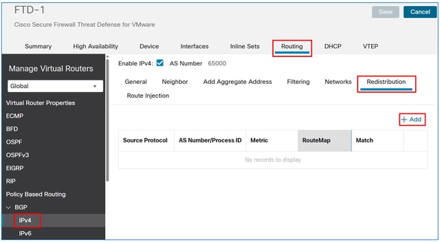
No campo Source Protocol, escolha Static e selecione o botão OK.
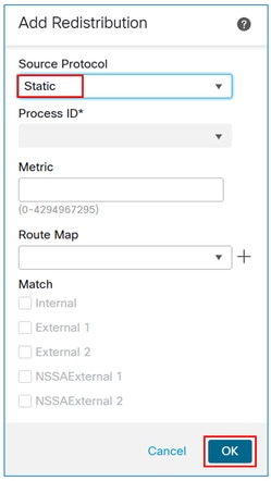
Cuidado: isso redistribui todas as rotas estáticas no BGP. Se você precisar anunciar apenas as sub-redes VPN, poderá aplicar um mapa de rotas para filtrá-las.
O resultado:
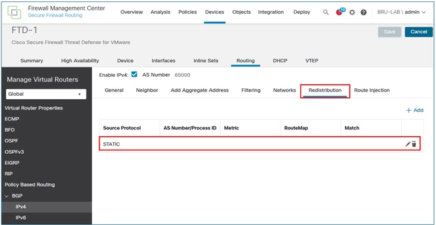
Salve e implante a configuração no FTD.
Verificar
Configuração de BGP de FTD:
FTD-HQ-1# show run router
router bgp 65000
 bgp log-neighbor-changes
 bgp router-id vrf auto-assign
 address-family ipv4 unicast
  neighbor 192.168.100.1 remote-as 65001
  neighbor 192.168.100.1 transport path-mtu-discovery disable
  neighbor 192.168.100.1 activate
  redistribute static
  no auto-summary
  no synchronization
 exit-address-family
Saída de tabela bgp FTD:
FTD-1# show bgp

BGP table version is 26, local router ID is 192.168.100.2
Status codes: s suppressed, d damped, h history, * valid, > best, i - internal,
              r RIB-failure, S Stale, m multipath
Origin codes: i - IGP, e - EGP, ? - incomplete
   Network          Next Hop        Metric LocPrf Weight  Path
*> 10.100.100.10/32 10.100.100.10        0         32768  ?
r> 192.168.100.0/30 192.168.100.1      1             0  65001 ?
Saída da tabela bgp de R1:
R1#show ip bgp

BGP table version is 259, local router ID is 192.168.100.1
Status codes: s suppressed, d damped, h history, * valid, > best, i - internal,
              r RIB-failure, S Stale, m multipath, b backup-path, f RT-Filter,
              x best-external, a additional-path, c RIB-compressed,
              t secondary path, L long-lived-stale,
Origin codes: i - IGP, e - EGP, ? - incomplete
RPKI validation codes: V valid, I invalid, N Not found

     Network          Next Hop            Metric LocPrf Weight Path
 *>   10.100.100.10/32 192.168.100.2           0             0 65000 ?
 *>   192.168.100.0/30  0.0.0.0                 1         32768 ?
Saída da tabela de roteamento de R1:
R1#show ip route

Codes: L - local, C - connected, S - static, R - RIP, M - mobile, B - BGP
       D - EIGRP, EX - EIGRP external, O - OSPF, IA - OSPF inter area
       N1 - OSPF NSSA external type 1, N2 - OSPF NSSA external type 2
       E1 - OSPF external type 1, E2 - OSPF external type 2, m - OMP
       n - NAT, Ni - NAT inside, No - NAT outside, Nd - NAT DIA
       i - IS-IS, su - IS-IS summary, L1 - IS-IS level-1, L2 - IS-IS level-2
       ia - IS-IS inter area, * - candidate default, U - per-user static route
       H - NHRP, G - NHRP registered, g - NHRP registration summary
       o - ODR, P - periodic downloaded static route, l - LISP
       a - application route
       + - replicated route, % - next hop override, p - overrides from PfR
       & - replicated local route overrides by connected

Gateway of last resort is not set

C        192.168.100.0/30 is directly connected, GigabitEthernet1
L        192.168.100.1/32 is directly connected, GigabitEthernet1
      10.0.0.0/32 is subnetted, 1 subnets
B        10.100.100.10 [20/0] via 192.168.100.2, 00:02:00
Tip: Observe que, embora o pool de VPN seja 10.100.100.0/24, o FTD redistribui uma sub-rede /32 sobre o BGP. Isso ocorre porque o FTD cria uma rota estática com um prefixo /32 para cada sessão de VPN de acesso remoto. Para otimizar isso, você pode usar o recurso de Endereço Agregado BGP.
Configuração de Endereço Agregado BGP
Configurar
Se ainda não tiver sido criado, crie um objeto de rede para as sub-redes VPN.

Na interface de usuário de gerenciamento de dispositivos do FMC, navegue para Routing > BGP > IPv4 > Add Aggregate Address e selecione o botão Add .
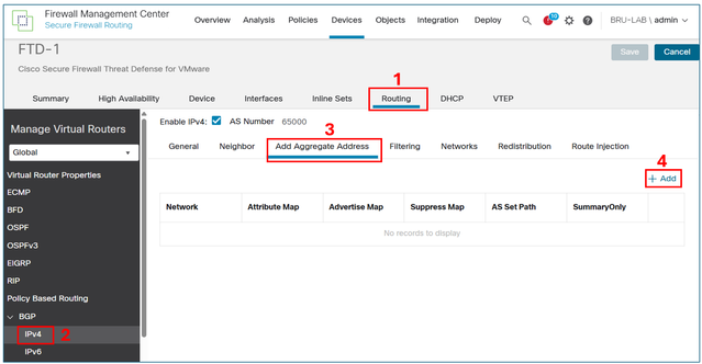
No campo network, adicione o objeto para a sub-rede VPN e marque a caixa de seleção Filter all routes from updates.
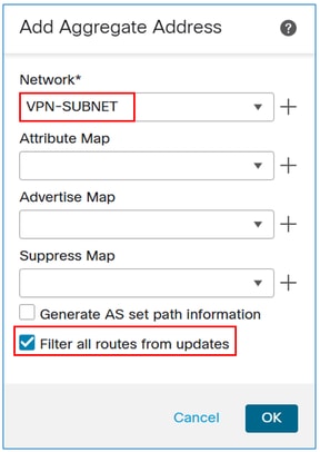
Note: Se a caixa de seleção Filtrar todas as rotas de atualizações estiver desmarcada, o FTD anunciará o endereço de resumo e as rotas de VPN /32 específicas sobre o BGP. Quando a caixa de seleção está habilitada, o FMC envia o comando aggregate-address summary-only para a configuração LINA do FTD, garantindo que apenas o endereço de resumo seja anunciado.
O resultado:
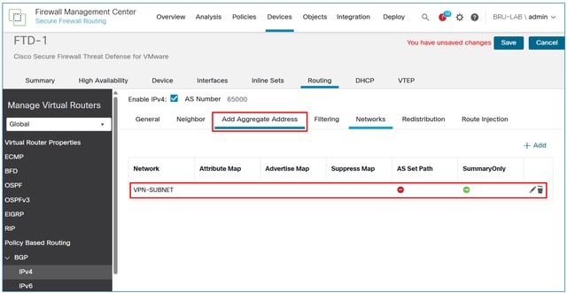
Salve e implante a configuração no FTD.
Verificar
Configuração de BGP de FTD:
FTD-1# sh run router
router bgp 65000
 bgp log-neighbor-changes
 bgp router-id vrf auto-assign
 address-family ipv4 unicast
  neighbor 192.168.100.1 remote-as 65001
  neighbor 192.168.100.1 transport path-mtu-discovery disable
  neighbor 192.168.100.1 activate
 redistribute static
  aggregate-address 10.100.100.0 255.255.255.0 summary-only
  no auto-summary
  no synchronization
 exit-address-family
Saída da tabela BGP de FTD:
FTD-1# sh bgp

BGP table version is 28, local router ID is 192.168.100.2
Status codes: s suppressed, d damped, h history, * valid, > best, i - internal,
              r RIB-failure, S Stale, m multipath
Origin codes: i - IGP, e - EGP, ? - incomplete

   Network          Next Hop        Metric LocPrf Weight  Path

*> 10.100.100.0/24  0.0.0.0                        32768  i
s> 10.100.100.10/32 10.100.100.10        0         32768  ?
r> 192.168.100.0/30 192.168.100.1       1             0  65001 ?
Saída da tabela BGP de R1:
R1#show ip bgp

BGP table version is 261, local router ID is 192.168.100.1
Status codes: s suppressed, d damped, h history, * valid, > best, i - internal,
              r RIB-failure, S Stale, m multipath, b backup-path, f RT-Filter,
              x best-external, a additional-path, c RIB-compressed,
              t secondary path, L long-lived-stale,
Origin codes: i - IGP, e - EGP, ? - incomplete
RPKI validation codes: V valid, I invalid, N Not found

     Network          Next Hop            Metric LocPrf Weight Path
*>   10.100.100.0/24  192.168.100.2          0             0 65000 i
 *>   192.168.100.0/30  0.0.0.0                  1         32768 ?
Saída da tabela de roteamento de R1:
R1#show ip route

Codes: L - local, C - connected, S - static, R - RIP, M - mobile, B - BGP
       D - EIGRP, EX - EIGRP external, O - OSPF, IA - OSPF inter area
       N1 - OSPF NSSA external type 1, N2 - OSPF NSSA external type 2
       E1 - OSPF external type 1, E2 - OSPF external type 2, m - OMP
       n - NAT, Ni - NAT inside, No - NAT outside, Nd - NAT DIA
       i - IS-IS, su - IS-IS summary, L1 - IS-IS level-1, L2 - IS-IS level-2
       ia - IS-IS inter area, * - candidate default, U - per-user static route
       H - NHRP, G - NHRP registered, g - NHRP registration summary
       o - ODR, P - periodic downloaded static route, l - LISP
       a - application route
       + - replicated route, % - next hop override, p - overrides from PfR
       & - replicated local route overrides by connected

Gateway of last resort is not set

C        192.168.100.0/30 is directly connected, GigabitEthernet1
L        192.168.100.1/32 is directly connected, GigabitEthernet1
      10.0.0.0/24 is subnetted, 1 subnets
B        10.100.100.0 [20/0] via 192.168.100.2, 00:02:04
Histórico de revisões
| Revisão | Data de publicação | Comentários |
|---|---|---|
1.0 |
05-May-2025
|
Versão inicial |
Colaborado por engenheiros da Cisco
- Luciano BezerraEngenheiro do Cisco TAC
 Feedback
Contate a Cisco
- Abrir um caso de suporte

- (É necessário um Contrato de Serviço da Cisco)