Advertise Remote Access VPN Subnets Through Routing Protocols in FTD
Available Languages
Download Options
Bias-Free Language
The documentation set for this product strives to use bias-free language. For the purposes of this documentation set, bias-free is defined as language that does not imply discrimination based on age, disability, gender, racial identity, ethnic identity, sexual orientation, socioeconomic status, and intersectionality. Exceptions may be present in the documentation due to language that is hardcoded in the user interfaces of the product software, language used based on RFP documentation, or language that is used by a referenced third-party product. Learn more about how Cisco is using Inclusive Language.
Contents
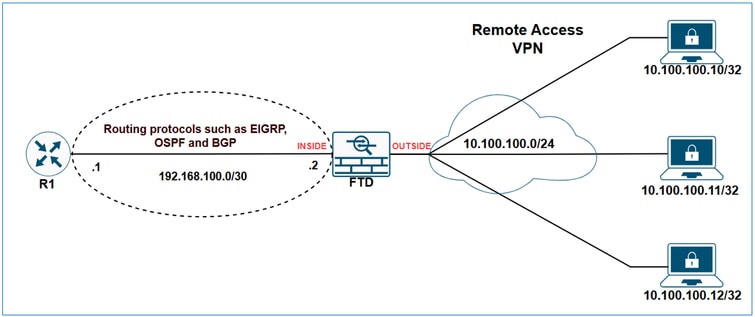
Introduction
This document describes the options available for advertising VPN-related subnets using the routing protocols EIGRP, OSPF, and BGP.
Prerequisites
Requirements
There are no specific requirements for this document.
Components Used
The information in this document was created from the devices in a specific lab environment. All of the devices used in this document started with a cleared (default) configuration. If your network is live, ensure that you understand the potential impact of any command.
The information in this document is based on these software and hardware versions:
- Cisco Secure Firewall Management Center 7.6.0
- Cisco Secure Firewall 7.6.0
Note: This document outlines the configuration for redistributing Remote Access VPN subnets through EIGRP, OSPF, and BGP using the FMC. For guidance on route redistribution with FDM, please refer to the FDM configuration guide.
Background Information
The first thing to understand is how the FTD classifies VPN subnets in its routing table. Although these subnets appear as connected by VPN, they are not considered directly connected subnets; instead, they are treated as static routes.
The show outputs demonstrate it.
FTD show route output:
FTD-1# show route

Codes: L - local, C - connected, S - static, R - RIP, M - mobile, B - BGP
       D - EIGRP, EX - EIGRP external, O - OSPF, IA - OSPF inter area
       N1 - OSPF NSSA external type 1, N2 - OSPF NSSA external type 2
       E1 - OSPF external type 1, E2 - OSPF external type 2, V - VPN
       i - IS-IS, su - IS-IS summary, L1 - IS-IS level-1, L2 - IS-IS level-2
       ia - IS-IS inter area, * - candidate default, U - per-user static route
       o - ODR, P - periodic downloaded static route, + - replicated route
       SI - Static InterVRF, BI - BGP InterVRF
Gateway of last resort is not set

C        10.10.20.0 255.255.255.0 is directly connected, outside
L        10.10.20.1 255.255.255.255 is directly connected, outside
C        192.168.100.0 255.255.255.252 is directly connected, inside
L        192.168.100.2 255.255.255.255 is directly connected, inside
V        10.100.100.10 255.255.255.255 connected by VPN (advertised), outside
FTD show route connected output:
FTD-1# show route connected

Codes: L - local, C - connected, S - static, R - RIP, M - mobile, B - BGP
       D - EIGRP, EX - EIGRP external, O - OSPF, IA - OSPF inter area
       N1 - OSPF NSSA external type 1, N2 - OSPF NSSA external type 2
       E1 - OSPF external type 1, E2 - OSPF external type 2, V - VPN
       i - IS-IS, su - IS-IS summary, L1 - IS-IS level-1, L2 - IS-IS level-2
       ia - IS-IS inter area, * - candidate default, U - per-user static route
       o - ODR, P - periodic downloaded static route, + - replicated route
       SI - Static InterVRF, BI - BGP InterVRF

Gateway of last resort is not set

C        10.10.20.0 255.255.255.0 is directly connected, outside
L        10.10.20.1 255.255.255.255 is directly connected, outside
C        192.168.100.0 255.255.255.252 is directly connected, inside
L        192.168.100.2 255.255.255.255 is directly connected, inside
FTD show route static output:
FTD-HQ-1# show route static

Codes: L - local, C - connected, S - static, R - RIP, M - mobile, B - BGP
       D - EIGRP, EX - EIGRP external, O - OSPF, IA - OSPF inter area
       N1 - OSPF NSSA external type 1, N2 - OSPF NSSA external type 2
       E1 - OSPF external type 1, E2 - OSPF external type 2, V - VPN
       i - IS-IS, su - IS-IS summary, L1 - IS-IS level-1, L2 - IS-IS level-2
       ia - IS-IS inter area, * - candidate default, U - per-user static route
       o - ODR, P - periodic downloaded static route, + - replicated route
       SI - Static InterVRF, BI - BGP InterVRF

Gateway of last resort is not set

V        10.100.100.10 255.255.255.255 connected by VPN (advertised), outside
Now that it is clear how VPN subnets are treated in the firewall's routing table, the next step is to explore how to advertise them using various routing protocols.
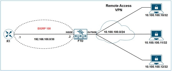
Redistribute Remote Access VPN Subnets through EIGRP on FTD
Network Diagram
Static routes that fall within the scope of a network statement are automatically redistributed to EIGRP; you do not need to define a redistribution rule for them. However, when redistributing static routes that point to VTI interfaces in EIGRP, you must specify the metric. For static routes pointing to other types of interfaces, specifying the metric is not required.
Due to EIGRP's behavior of automatically redistributing static routes that fall within the scope of network statements, there are two options for advertising VPN subnets via EIGRP on FTD:
- Using a network statement.
- Using the redistribute static approach.
In this example the goal is to make R1 learn the VPN subnet 10.100.100.0/24 via EIGRP.
FTD initial configuration:
hostname FTD-1
!
ip local pool VPN-POOL1 10.100.100.10-10.100.100.254 mask 255.255.255.0
!
webvpn
...
  group-policy LAB_GROUP1 internal
group-policy LAB_GROUP1 attributes
...
  address-pools value VPN-POOL1
!
router eigrp 100
 no default-information in
 no default-information out
 no eigrp log-neighbor-warnings
 no eigrp log-neighbor-changes
network 192.168.100.0 255.255.255.252
FTD Initial routing table:
FTD-1# show route

Codes: L - local, C - connected, S - static, R - RIP, M - mobile, B - BGP
       D - EIGRP, EX - EIGRP external, O - OSPF, IA - OSPF inter area
       N1 - OSPF NSSA external type 1, N2 - OSPF NSSA external type 2
       E1 - OSPF external type 1, E2 - OSPF external type 2, V - VPN
       i - IS-IS, su - IS-IS summary, L1 - IS-IS level-1, L2 - IS-IS level-2
       ia - IS-IS inter area, * - candidate default, U - per-user static route
       o - ODR, P - periodic downloaded static route, + - replicated route
       SI - Static InterVRF, BI - BGP InterVRF

Gateway of last resort is not set

C        10.10.20.0 255.255.255.0 is directly connected, outside
L        10.10.20.1 255.255.255.255 is directly connected, outside
C        192.168.100.0 255.255.255.252 is directly connected, inside
L        192.168.100.2 255.255.255.255 is directly connected, inside
V       10.100.100.10 255.255.255.255 connected by VPN (advertised), outside
FTD Initial EIGRP topology table:
FTD-1# show eigrp topology

EIGRP-IPv4 Topology Table for AS(100)/ID(192.168.100.2)
Codes: P - Passive, A - Active, U - Update, Q - Query, R - Reply,
       r - reply Status, s - sia Status

P 192.168.100.0 255.255.255.252, 1 successors, FD is 512 via Connected, inside
R1 Initial Routing table:
R1#show ip route

Codes: L - local, C - connected, S - static, R - RIP, M - mobile, B - BGP
       D - EIGRP, EX - EIGRP external, O - OSPF, IA - OSPF inter area
       N1 - OSPF NSSA external type 1, N2 - OSPF NSSA external type 2
       E1 - OSPF external type 1, E2 - OSPF external type 2, m - OMP
       n - NAT, Ni - NAT inside, No - NAT outside, Nd - NAT DIA
       i - IS-IS, su - IS-IS summary, L1 - IS-IS level-1, L2 - IS-IS level-2
       ia - IS-IS inter area, * - candidate default, U - per-user static route
       H - NHRP, G - NHRP registered, g - NHRP registration summary
       o - ODR, P - periodic downloaded static route, l - LISP
       a - application route
       + - replicated route, % - next hop override, p - overrides from PfR
       & - replicated local route overrides by connected

Gateway of last resort is not set

C        192.168.100.0/30 is directly connected, GigabitEthernet1
L        192.168.100.1/32 is directly connected, GigabitEthernet1
Redistribute Remote Access VPN Subnets through EIGRP on FTD using network statement
Configure
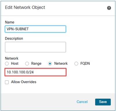
Step 1. Create a network object for the VPN subnet.
Step 2. Include the VPN subnet object in the network statement.
In the FMC device management UI, navigate to Routing > EIGRP > Setup, and include the VPN subnet in the selected networks/hosts.
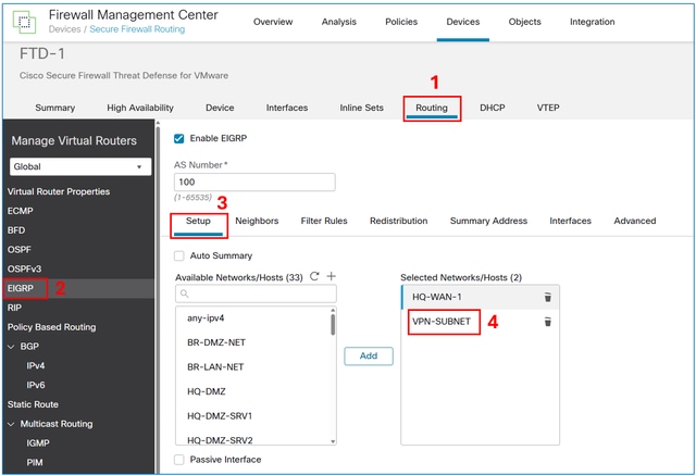
Save and deploy the configuration on the FTD.
Verify
FTD EIGRP configuration:
FTD-1# show run router
router eigrp 100
 no default-information in
 no default-information out
 no eigrp log-neighbor-warnings
 no eigrp log-neighbor-changes
 network 10.100.100.0 255.255.255.0
 network 192.168.100.0 255.255.255.252
FTD EIGRP topoloty table:
FTD-1# show eigrp topology

EIGRP-IPv4 Topology Table for AS(100)/ID(192.168.100.2)
Codes: P - Passive, A - Active, U - Update, Q - Query, R - Reply,
       r - reply Status, s - sia Status

P 10.100.100.10 255.255.255.255, 1 successors, FD is 512
        via Rstatic (512/0)

P 192.168.100.0 255.255.255.252, 1 successors, FD is 512
        via Connected, inside
R1 routing table:
R1#show ip route

Codes: L - local, C - connected, S - static, R - RIP, M - mobile, B - BGP
       D - EIGRP, EX - EIGRP external, O - OSPF, IA - OSPF inter area
       N1 - OSPF NSSA external type 1, N2 - OSPF NSSA external type 2
       E1 - OSPF external type 1, E2 - OSPF external type 2, m - OMP
       n - NAT, Ni - NAT inside, No - NAT outside, Nd - NAT DIA
       i - IS-IS, su - IS-IS summary, L1 - IS-IS level-1, L2 - IS-IS level-2
       ia - IS-IS inter area, * - candidate default, U - per-user static route
       H - NHRP, G - NHRP registered, g - NHRP registration summary
       o - ODR, P - periodic downloaded static route, l - LISP
       a - application route
       + - replicated route, % - next hop override, p - overrides from PfR
       & - replicated local route overrides by connected


Gateway of last resort is not set

C        192.168.100.0/30 is directly connected, GigabitEthernet1
L        192.168.100.1/32 is directly connected, GigabitEthernet1
      10.0.0.0/32 is subnetted, 1 subnets
D        10.100.100.10
           [90/3072] via 192.168.100.2, 00:02:17, GigabitEthernet1
Note: Note that although the network statement was 10.100.100.0/24, the FTD redistributes a /32 subnet over EIGRP. This occurs because the FTD creates a static route with a /32 prefix for every remote access VPN session. To optimize this, you can use the EIGRP Summary Address feature.
Redistribute Remote Access VPN Subnets through EIGRP on FTD using the redistribute static approach
Configure
In the FMC device management UI, navigate to Routing > EIGRP > Redistribution, and then select the Add button.
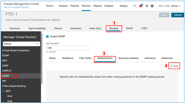
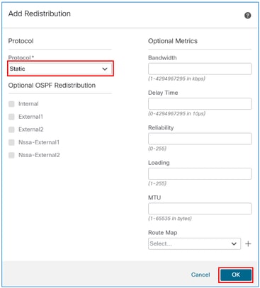
In the protocol field, select Static, and then select the OK button.
Caution: This redistributes all static routes into EIGRP. If you need to advertise only the VPN subnets, you can either use the network statement approach or apply a route map to filter them.
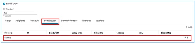
The result:
Save and deploy the configuration on the FTD.
Verify
FTD EIGRP configuration:
FTD-HQ-1# show run router

router eigrp 100
 no default-information in
 no default-information out
 no eigrp log-neighbor-warnings
 no eigrp log-neighbor-changes
 network 192.168.100.0 255.255.255.252
 redistribute static
FTD EIGRP topoloty table:
FTD-1# show eigrp topology
EIGRP-IPv4 Topology Table for AS(100)/ID(192.168.100.2)
Codes: P - Passive, A - Active, U - Update, Q - Query, R - Reply,
       r - reply Status, s - sia Status

P 10.100.100.10 255.255.255.255, 1 successors, FD is 512
        via Rstatic (512/0)
P 192.168.100.0 255.255.255.252, 1 successors, FD is 512
        via Connected, inside
R1 routing table:
R1#show ip route

Codes: L - local, C - connected, S - static, R - RIP, M - mobile, B - BGP
       D - EIGRP, EX - EIGRP external, O - OSPF, IA - OSPF inter area
       N1 - OSPF NSSA external type 1, N2 - OSPF NSSA external type 2
       E1 - OSPF external type 1, E2 - OSPF external type 2, m - OMP
       n - NAT, Ni - NAT inside, No - NAT outside, Nd - NAT DIA
       i - IS-IS, su - IS-IS summary, L1 - IS-IS level-1, L2 - IS-IS level-2
       ia - IS-IS inter area, * - candidate default, U - per-user static route
       H - NHRP, G - NHRP registered, g - NHRP registration summary
       o - ODR, P - periodic downloaded static route, l - LISP
       a - application route
       + - replicated route, % - next hop override, p - overrides from PfR
       & - replicated local route overrides by connected

Gateway of last resort is not set

C        192.168.100.0/30 is directly connected, GigabitEthernet1
L        192.168.100.1/32 is directly connected, GigabitEthernet1
D EX     10.100.100.10
           [170/3072] via 192.168.100.2, 00:03:52, GigabitEthernet1
Tip: Optionally, you can use the EIGRP summary address feature on FTD to optimize the size of the routing table.
EIGRP Summary Address Configuration
Configure
If it has not been created yet, create a network object for the VPN subnets.

In the FMC device management UI, navigate to Routing > EIGRP > Summary Address, and then select the Add button.
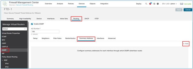
In the interface field, enter the one facing the EIGRP neighbor, and in the network field, enter the object created for the VPN subnet.
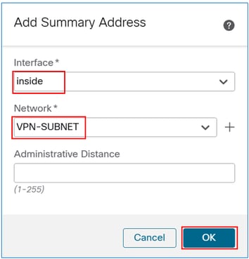
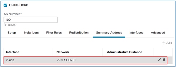
The result:
Verify
FTD EIGRP Summary Address configuration:
FTD-1# sh run interface

interface GigabitEthernet0/0
 nameif inside
 security-level 0
 zone-member inside
 ip address 192.168.100.2 255.255.255.252
summary-address eigrp 100 10.100.100.0 255.255.255.0
FTD EIGRP topoloty table:
FTD-1# show eigrp topology

EIGRP-IPv4 Topology Table for AS(100)/ID(192.168.100.2)
Codes: P - Passive, A - Active, U - Update, Q - Query, R - Reply,
       r - reply Status, s - sia Status

P 10.100.100.10 255.255.255.255, 1 successors, FD is 512
        via Rstatic (512/0)
P 10.100.100.0 255.255.255.0, 1 successors, FD is 512
        via Summary (512/0), Null0
P 192.168.100.0 255.255.255.0, 1 successors, FD is 512
        via Connected, inside
R1 routing table:
R1#show ip route

Codes: L - local, C - connected, S - static, R - RIP, M - mobile, B - BGP
       D - EIGRP, EX - EIGRP external, O - OSPF, IA - OSPF inter area
       N1 - OSPF NSSA external type 1, N2 - OSPF NSSA external type 2
       E1 - OSPF external type 1, E2 - OSPF external type 2, m - OMP
       n - NAT, Ni - NAT inside, No - NAT outside, Nd - NAT DIA
       i - IS-IS, su - IS-IS summary, L1 - IS-IS level-1, L2 - IS-IS level-2
       ia - IS-IS inter area, * - candidate default, U - per-user static route
       H - NHRP, G - NHRP registered, g - NHRP registration summary
       o - ODR, P - periodic downloaded static route, l - LISP
       a - application route
       + - replicated route, % - next hop override, p - overrides from PfR
       & - replicated local route overrides by connected

Gateway of last resort is not set

C        192.168.100.0/30 is directly connected, GigabitEthernet1
L        192.168.100.1/32 is directly connected, GigabitEthernet1
      10.0.0.0/24 is subnetted, 1 subnets
D        10.100.100.0 [90/3072] via 192.168.100.2, 00:01:54, GigabitEthernet1
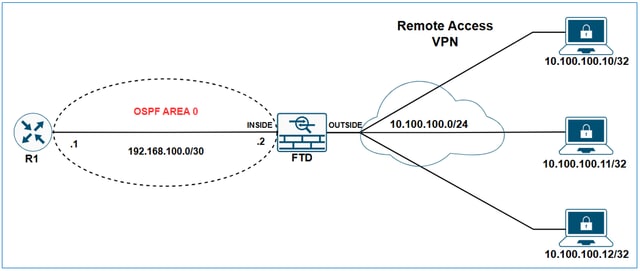
Redistribute Remote Access VPN Subnets through OSPF on FTD
Network Diagram
Initial configurations
ip local pool VPN-POOL1 10.100.100.10-10.100.100.254 mask 255.255.255.0
!
webvpn
  group-policy LAB_GROUP1 internal
...
group-policy LAB_GROUP1 attributes
...
  address-pools value VPN-POOL1
!
router ospf 1
network 192.168.100.0 255.255.255.252 area 0
FTD show ospf neighbor output:
FTD-1# show ospf neighbor

Neighbor ID     Pri   State           Dead Time   Address         Interface
192.168.100.1          1   FULL/DR         0:00:39     192.168.100.1   inside
R1 show ip ospf neighbor output:
R1#show ip ospf neighbor

Neighbor ID     Pri   State           Dead Time   Address         Interface
192.168.100.2    1   FULL/BDR        00:00:37    192.168.100.2  GigabitEthernet1
R1 routing table:
R1#show ip route

Codes: L - local, C - connected, S - static, R - RIP, M - mobile, B - BGP
       D - EIGRP, EX - EIGRP external, O - OSPF, IA - OSPF inter area
       N1 - OSPF NSSA external type 1, N2 - OSPF NSSA external type 2
       E1 - OSPF external type 1, E2 - OSPF external type 2, m - OMP
       n - NAT, Ni - NAT inside, No - NAT outside, Nd - NAT DIA
       i - IS-IS, su - IS-IS summary, L1 - IS-IS level-1, L2 - IS-IS level-2
       ia - IS-IS inter area, * - candidate default, U - per-user static route
       H - NHRP, G - NHRP registered, g - NHRP registration summary
       o - ODR, P - periodic downloaded static route, l - LISP
       a - application route
       + - replicated route, % - next hop override, p - overrides from PfR
       & - replicated local route overrides by connected

Gateway of last resort is not set

C        192.168.100.0/30 is directly connected, GigabitEthernet1
L        192.168.100.1/32 is directly connected, GigabitEthernet1
Configure
In the FMC device management UI, navigate to Routing > OSPF > Redistribution, and then select the Add button.
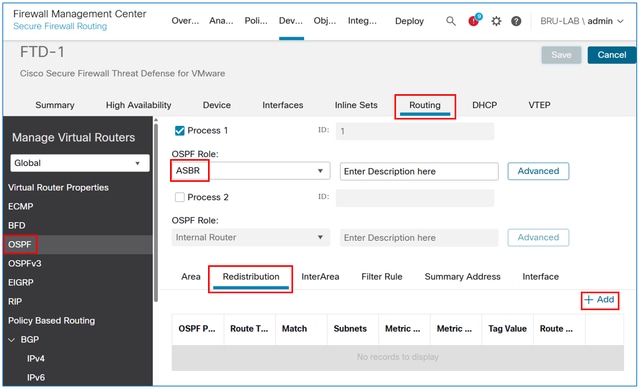
Note: The OSPF role must be set as ASBR or ABR & ASBR to enable redistribution.
In the Route Type field, select Static, and then check the Use Subnets box.
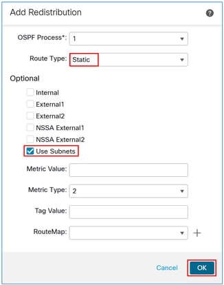
Caution: This redistributes all static routes into OSPF. If you need to advertise only the VPN subnets, you can apply a route map to filter them.
The result:

Verify
FTD OSPF redistribution configuration:
FTD-1# sh run router
router ospf 1
 network 192.168.100.0 255.255.255.252 area 0
 redistribute static subnets
R1 routing table:
R1#show ip route

Codes: L - local, C - connected, S - static, R - RIP, M - mobile, B - BGP
       D - EIGRP, EX - EIGRP external, O - OSPF, IA - OSPF inter area
       N1 - OSPF NSSA external type 1, N2 - OSPF NSSA external type 2
       E1 - OSPF external type 1, E2 - OSPF external type 2, m - OMP
       n - NAT, Ni - NAT inside, No - NAT outside, Nd - NAT DIA
       i - IS-IS, su - IS-IS summary, L1 - IS-IS level-1, L2 - IS-IS level-2
       ia - IS-IS inter area, * - candidate default, U - per-user static route
       H - NHRP, G - NHRP registered, g - NHRP registration summary
       o - ODR, P - periodic downloaded static route, l - LISP
       a - application route
       + - replicated route, % - next hop override, p - overrides from PfR
       & - replicated local route overrides by connected

Gateway of last resort is not set

C        192.168.100.0/30 is directly connected, GigabitEthernet1
L        192.168.100.1/32 is directly connected, GigabitEthernet1
      10.0.0.0/32 is subnetted, 1 subnets
O E2     10.100.100.10 [110/20] via 192.168.100.2, 00:08:01, GigabitEthernet1
Tip: Note that although the VPN pool is 10.100.100.0/24, the FTD redistributes a /32 subnet over OSPF. This occurs because the FTD creates a static route with a /32 prefix for every remote access VPN session. To optimize this, you can use the OSPF Summary Address feature.
OSPF Summary Address Configuration
Configure
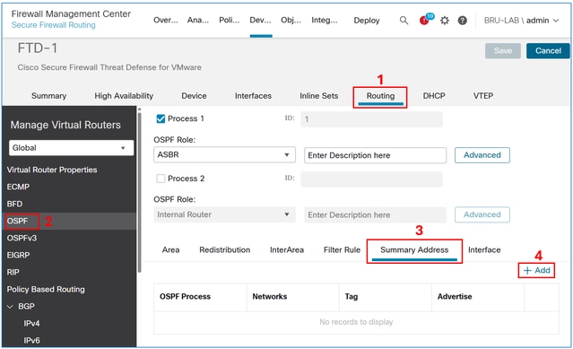
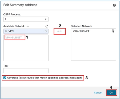
If it has not been created yet, create a network object for the VPN subnets.

In the FMC device management UI, navigate to Routing > OSPF> Summary Address, and then select the Add button.
Add the VPN subnet object and select the Advertise checkbox.
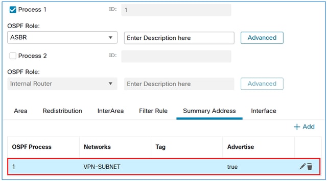
The Result:
Verify
FTD OSPF configuration:
FTD-1# sh run router

router ospf 1
 network 192.168.100.0 255.255.255.252 area 0
redistribute static subnets
 summary-address 10.100.100.0 255.255.255.0
R1 routing table:
R1#sh ip route

Codes: L - local, C - connected, S - static, R - RIP, M - mobile, B - BGP
       D - EIGRP, EX - EIGRP external, O - OSPF, IA - OSPF inter area
       N1 - OSPF NSSA external type 1, N2 - OSPF NSSA external type 2
       E1 - OSPF external type 1, E2 - OSPF external type 2, m - OMP
       n - NAT, Ni - NAT inside, No - NAT outside, Nd - NAT DIA
       i - IS-IS, su - IS-IS summary, L1 - IS-IS level-1, L2 - IS-IS level-2
       ia - IS-IS inter area, * - candidate default, U - per-user static route
       H - NHRP, G - NHRP registered, g - NHRP registration summary
       o - ODR, P - periodic downloaded static route, l - LISP
       a - application route
       + - replicated route, % - next hop override, p - overrides from PfR
       & - replicated local route overrides by connected

Gateway of last resort is not set

C        192.168.100.0/30 is directly connected, GigabitEthernet1
L        192.168.100.1/32 is directly connected, GigabitEthernet1
      10.0.0.0/24 is subnetted, 1 subnets
O E2     10.100.100.0 [110/20] via 192.168.100.2, 00:00:26, GigabitEthernet1
Redistribute Remote Access VPN Subnets through eBGP on FTD
Network Diagram
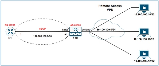
In this example the goal is to make R1 learn the VPN subnet 10.100.100.0/24 via eBGP.
Initial configurations
FTD Initial configuration:
hostname FTD-1
!
ip local pool VPN-POOL1 10.100.100.10-10.100.100.254 mask 255.255.255.0
!
webvpn
...
  group-policy LAB_GROUP1 internal
group-policy LAB_GROUP1 attributes
...
  address-pools value VPN-POOL1
!
router bgp 65000
 bgp log-neighbor-changes
 bgp router-id vrf auto-assign
 address-family ipv4 unicast
  neighbor 192.168.100.1 remote-as 65001
  neighbor 192.168.100.1 transport path-mtu-discovery disable
  neighbor 192.168.100.1 activate
  no auto-summary
  no synchronization
 exit-address-family
FTD bgp table output:
FTD-1# show bgp

BGP table version is 25, local router ID is 192.168.100.2
Status codes: s suppressed, d damped, h history, * valid, > best, i - internal,
              r RIB-failure, S Stale, m multipath
Origin codes: i - IGP, e - EGP, ? - incomplete

Network               Next Hop        Metric LocPrf Weight  Path
r> 192.168.100.0/30  192.168.100.1       1             0  65001 ?
FTD show bgp summary output:
FTD-1# show bgp summary
BGP router identifier 192.168.100.2, local AS number 65000
BGP table version is 25, main routing table version 25
1 network entries using 2000 bytes of memory
17 path entries using 1360 bytes of memory
3/3 BGP path/bestpath attribute entries using 624 bytes of memory
2 BGP AS-PATH entries using 48 bytes of memory
0 BGP route-map cache entries using 0 bytes of memory
0 BGP filter-list cache entries using 0 bytes of memory
BGP using 4032 total bytes of memory
BGP activity 176/166 prefixes, 257/240 paths, scan interval 60 secs

Neighbor        V           AS MsgRcvd MsgSent   TblVer  InQ OutQ Up/Down  State/PfxRcd
192.168.100.1  4        65001 4589    3769          25    0    0 2d21h  8
R1 show ip bgp summary output:
R1#sh ip bgp summary
BGP router identifier 192.168.100.1, local AS number 65001
BGP table version is 258, main routing table version 258
1 network entries using 2480 bytes of memory
1 path entries using 2312 bytes of memory
1/1 BGP path/bestpath attribute entries using 864 bytes of memory
1 BGP AS-PATH entries using 64 bytes of memory
0 BGP route-map cache entries using 0 bytes of memory
0 BGP filter-list cache entries using 0 bytes of memory
BGP using 5720 total bytes of memory
BGP activity 85/75 prefixes, 244/227 paths, scan interval 60 secs
12 networks peaked at 11:10:00 Apr 17 2025 UTC (00:06:27.485 ago)

Neighbor        V           AS MsgRcvd MsgSent   TblVer  InQ OutQ Up/Down  State/PfxRcd
192.168.100.2  4        65000    3770    4590      258    0    0 2d21h           9
R1 bgp table output:
R1#show ip bgp
BGP table version is 258, local router ID is 192.168.100.1
Status codes: s suppressed, d damped, h history, * valid, > best, i - internal,
             r RIB-failure, S Stale, m multipath, b backup-path, f RT-Filter,
              x best-external, a additional-path, c RIB-compressed,
              t secondary path, L long-lived-stale,
Origin codes: i - IGP, e - EGP, ? - incomplete
RPKI validation codes: V valid, I invalid, N Not found
       Network          Next Hop            Metric LocPrf Weight Path
 *>   192.168.100.0/30                      0.0.0.0                  1         32768 ?
R1 routing table:
R1#show ip route
Codes: L - local, C - connected, S - static, R - RIP, M - mobile, B - BGP
       D - EIGRP, EX - EIGRP external, O - OSPF, IA - OSPF inter area
       N1 - OSPF NSSA external type 1, N2 - OSPF NSSA external type 2
       E1 - OSPF external type 1, E2 - OSPF external type 2, m - OMP
       n - NAT, Ni - NAT inside, No - NAT outside, Nd - NAT DIA
       i - IS-IS, su - IS-IS summary, L1 - IS-IS level-1, L2 - IS-IS level-2
       ia - IS-IS inter area, * - candidate default, U - per-user static route
       H - NHRP, G - NHRP registered, g - NHRP registration summary
       o - ODR, P - periodic downloaded static route, l - LISP
       a - application route
       + - replicated route, % - next hop override, p - overrides from PfR
       & - replicated local route overrides by connected

Gateway of last resort is not set

C        192.168.100.0/30 is directly connected, GigabitEthernet1
L        192.168.100.1/32 is directly connected, GigabitEthernet1
Configure
In the FMC device management UI, navigate to Routing > BGP > IPv4 > Redistribution, and then select the Add button.
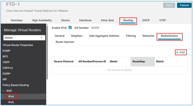
In the Source Protocol field, choose Static, and then select the OK button.
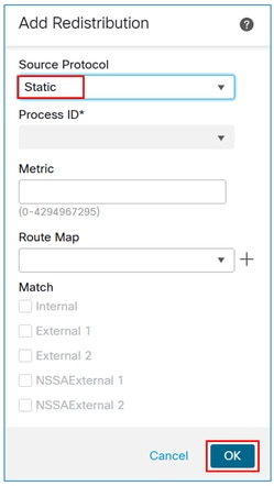
Caution: This redistributes all static routes into BGP. If you need to advertise only the VPN subnets, you can apply a route map to filter them.
The result:
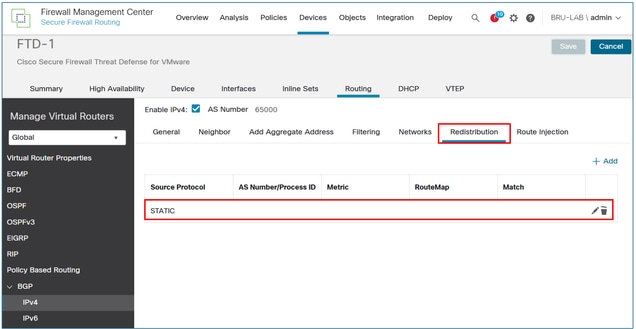
Save and deploy the configuration on the FTD.
Verify
FTD BGP configuration:
FTD-HQ-1# show run router
router bgp 65000
 bgp log-neighbor-changes
 bgp router-id vrf auto-assign
 address-family ipv4 unicast
  neighbor 192.168.100.1 remote-as 65001
  neighbor 192.168.100.1 transport path-mtu-discovery disable
  neighbor 192.168.100.1 activate
  redistribute static
  no auto-summary
  no synchronization
 exit-address-family
FTD bgp table output:
FTD-1# show bgp

BGP table version is 26, local router ID is 192.168.100.2
Status codes: s suppressed, d damped, h history, * valid, > best, i - internal,
              r RIB-failure, S Stale, m multipath
Origin codes: i - IGP, e - EGP, ? - incomplete
   Network          Next Hop        Metric LocPrf Weight  Path
*> 10.100.100.10/32 10.100.100.10        0         32768  ?
r> 192.168.100.0/30 192.168.100.1      1             0  65001 ?
R1 bgp table output:
R1#show ip bgp

BGP table version is 259, local router ID is 192.168.100.1
Status codes: s suppressed, d damped, h history, * valid, > best, i - internal,
              r RIB-failure, S Stale, m multipath, b backup-path, f RT-Filter,
              x best-external, a additional-path, c RIB-compressed,
              t secondary path, L long-lived-stale,
Origin codes: i - IGP, e - EGP, ? - incomplete
RPKI validation codes: V valid, I invalid, N Not found

     Network          Next Hop            Metric LocPrf Weight Path
 *>   10.100.100.10/32 192.168.100.2           0             0 65000 ?
 *>   192.168.100.0/30  0.0.0.0                 1         32768 ?
R1 routing table output:
R1#show ip route

Codes: L - local, C - connected, S - static, R - RIP, M - mobile, B - BGP
       D - EIGRP, EX - EIGRP external, O - OSPF, IA - OSPF inter area
       N1 - OSPF NSSA external type 1, N2 - OSPF NSSA external type 2
       E1 - OSPF external type 1, E2 - OSPF external type 2, m - OMP
       n - NAT, Ni - NAT inside, No - NAT outside, Nd - NAT DIA
       i - IS-IS, su - IS-IS summary, L1 - IS-IS level-1, L2 - IS-IS level-2
       ia - IS-IS inter area, * - candidate default, U - per-user static route
       H - NHRP, G - NHRP registered, g - NHRP registration summary
       o - ODR, P - periodic downloaded static route, l - LISP
       a - application route
       + - replicated route, % - next hop override, p - overrides from PfR
       & - replicated local route overrides by connected

Gateway of last resort is not set

C        192.168.100.0/30 is directly connected, GigabitEthernet1
L        192.168.100.1/32 is directly connected, GigabitEthernet1
      10.0.0.0/32 is subnetted, 1 subnets
B        10.100.100.10 [20/0] via 192.168.100.2, 00:02:00
Tip: Note that although the VPN pool is 10.100.100.0/24, the FTD redistributes a /32 subnet over BGP. This occurs because the FTD creates a static route with a /32 prefix for every remote access VPN session. To optimize this, you can use the BGP Aggregate Address feature.
BGP Aggregate Address Configuration
Configure
If it has not been created yet, create a network object for the VPN subnets.

In the FMC device management UI, navigate to Routing > BGP> IPv4 > Add Aggregate Address, and then select the Add button.
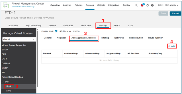
In the network field, add the object for the VPN subnet, and then select the Filter all routes from updates checkbox.
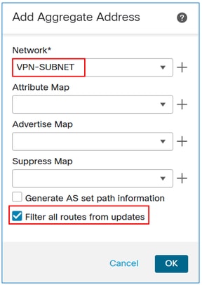
Note: If the Filter all routes from updates checkbox is unchecked, the FTD advertise both the summary address and the specific /32 VPN routes over BGP. When the checkbox is enabled, the FMC pushes the command aggregate-address summary-only to the FTD LINA configuration, ensuring that only the summary address is advertised.
The result:
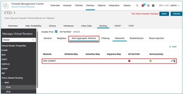
Save and deploy the configuration on the FTD.
Verify
FTD BGP configuration:
FTD-1# sh run router
router bgp 65000
 bgp log-neighbor-changes
 bgp router-id vrf auto-assign
 address-family ipv4 unicast
  neighbor 192.168.100.1 remote-as 65001
  neighbor 192.168.100.1 transport path-mtu-discovery disable
  neighbor 192.168.100.1 activate
 redistribute static
  aggregate-address 10.100.100.0 255.255.255.0 summary-only
  no auto-summary
  no synchronization
 exit-address-family
FTD BGP table output:
FTD-1# sh bgp

BGP table version is 28, local router ID is 192.168.100.2
Status codes: s suppressed, d damped, h history, * valid, > best, i - internal,
              r RIB-failure, S Stale, m multipath
Origin codes: i - IGP, e - EGP, ? - incomplete

   Network          Next Hop        Metric LocPrf Weight  Path

*> 10.100.100.0/24  0.0.0.0                        32768  i
s> 10.100.100.10/32 10.100.100.10        0         32768  ?
r> 192.168.100.0/30 192.168.100.1       1             0  65001 ?
R1 BGP table output:
R1#show ip bgp

BGP table version is 261, local router ID is 192.168.100.1
Status codes: s suppressed, d damped, h history, * valid, > best, i - internal,
              r RIB-failure, S Stale, m multipath, b backup-path, f RT-Filter,
              x best-external, a additional-path, c RIB-compressed,
              t secondary path, L long-lived-stale,
Origin codes: i - IGP, e - EGP, ? - incomplete
RPKI validation codes: V valid, I invalid, N Not found

     Network          Next Hop            Metric LocPrf Weight Path
*>   10.100.100.0/24  192.168.100.2          0             0 65000 i
 *>   192.168.100.0/30  0.0.0.0                  1         32768 ?
R1 routing table output:
R1#show ip route

Codes: L - local, C - connected, S - static, R - RIP, M - mobile, B - BGP
       D - EIGRP, EX - EIGRP external, O - OSPF, IA - OSPF inter area
       N1 - OSPF NSSA external type 1, N2 - OSPF NSSA external type 2
       E1 - OSPF external type 1, E2 - OSPF external type 2, m - OMP
       n - NAT, Ni - NAT inside, No - NAT outside, Nd - NAT DIA
       i - IS-IS, su - IS-IS summary, L1 - IS-IS level-1, L2 - IS-IS level-2
       ia - IS-IS inter area, * - candidate default, U - per-user static route
       H - NHRP, G - NHRP registered, g - NHRP registration summary
       o - ODR, P - periodic downloaded static route, l - LISP
       a - application route
       + - replicated route, % - next hop override, p - overrides from PfR
       & - replicated local route overrides by connected

Gateway of last resort is not set

C        192.168.100.0/30 is directly connected, GigabitEthernet1
L        192.168.100.1/32 is directly connected, GigabitEthernet1
      10.0.0.0/24 is subnetted, 1 subnets
B        10.100.100.0 [20/0] via 192.168.100.2, 00:02:04
Revision History
| Revision | Publish Date | Comments |
|---|---|---|
1.0 |
05-May-2025
|
Initial Release |
Contributed by Cisco Engineers
- Luciano BezerraCisco TAC Engineer
 Feedback
Contact Cisco
- Open a Support Case

- (Requires a Cisco Service Contract)