ブレード サーバのカバーの取り外し
手順
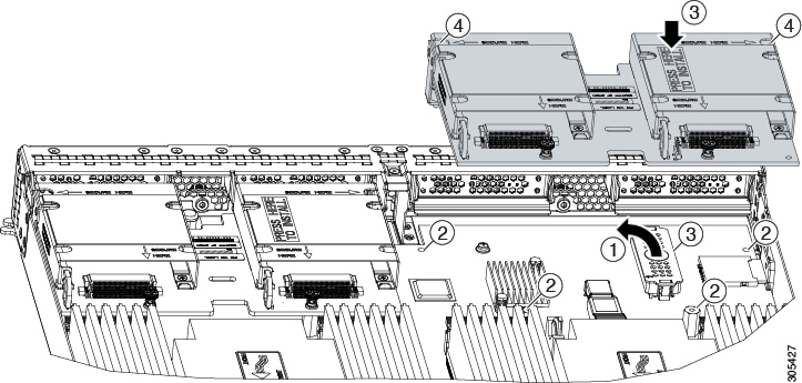
| ステップ 1 |
次の図に示すようにボタンを押し続けます。 |
| ステップ 2 |
カバーのバック エンドをつかんでカバーを後方に引き、引き上げます。 |
The documentation set for this product strives to use bias-free language. For the purposes of this documentation set, bias-free is defined as language that does not imply discrimination based on age, disability, gender, racial identity, ethnic identity, sexual orientation, socioeconomic status, and intersectionality. Exceptions may be present in the documentation due to language that is hardcoded in the user interfaces of the product software, language used based on RFP documentation, or language that is used by a referenced third-party product. Learn more about how Cisco is using Inclusive Language.
この章は、次の項で構成されています。
| ステップ 1 |
次の図に示すようにボタンを押し続けます。 |
| ステップ 2 |
カバーのバック エンドをつかんでカバーを後方に引き、引き上げます。 |
ハード ドライブは、ブレード サーバをシャーシから取り外さなくても取り外しと取り付けが可能です。
このブレード サーバでサポートされるドライブには、ドライブ スレッドが取り付けられています。スペアのドライブ スレッドは付属していません。現在サポートされているドライブの一覧は、『Cisco UCS B420 M4 Blade Server Specification Sheet』に記載されています。
稼働中の ブレード サーバでドライブをアップグレードまたは追加する前に、Cisco UCS Manager のサービス プロファイルを確認し、新しいハードウェア設定が、サービス プロファイルで設定されているパラメータの範囲内になることを確認します。
 注意 |
静電破壊を防止するために、作業中は静電気防止用リスト ストラップを着用してください。 |
 (注) |
4K セクター形式の SAS/SATA ドライブの考慮事項も参照してください。 |
ブレード サーバからハード ドライブを取り外すには、次の手順に従います。
| ステップ 1 |
ボタンを押してイジェクタを解除し、スロットからハード ドライブを引き出します。 |
| ステップ 2 |
取り外したハード ドライブをすぐに別のサーバに取り付けない場合は、静電気防止用マットまたは静電気防止用フォームの上にハード ドライブを置きます。 |
| ステップ 3 |
スロットを空のままにする場合は、ブレード サーバにほこりが入らないようにハード ディスク ドライブのブランク前面プレートを取り付けます。 |
ブレード サーバにドライブを取り付けるには、次の手順に従います。
| ステップ 1 |
解除ボタンを押してドライブ イジェクタを開きます。 |
| ステップ 2 |
ブレード サーバの開口部にドライブを差し込んでゆっくりと押し込み装着します。 |
| ステップ 3 |
ドライブ イジェクタを押して閉じます。 RAID サービスのフォーマットと設定には Cisco UCS Manager を使用できます。詳細については、次を参照してください。 使用しているバージョンの Cisco UCS Manager の構成ガイド設定ガイドは、次の URL で入手できます。http://www.cisco.com/en/US/products/ps10281/products_installation_and_configuration_guides_list.html RAID クラスタを移動する必要がある場合は、『Cisco UCS Manager Troubleshooting Reference Guide』を参照してください。 |
4K セクター形式のドライブはレガシー モードではなく UEFI モードで起動する必要があります。ブート ポリシーで UEFI ブート モードを設定するには、このセクションの手順を参照してください。
同じ RAID ボリュームの一部として 4K セクター形式および 512 バイト セクター形式のドライブを設定しないでください。
4K セクターのドライブでのオペレーティング システムのサポートは次のとおりです。Windows:Win2012、Win2012R2、Linux:RHEL 6.5、6.5、6.6、6.7、7.0、7.2、7.3、SLES 11 SP3 および SLES 12。ESXi/VMware はサポートされません。
| ステップ 1 |
[Navigation] ペインで [Servers] をクリックします。 |
| ステップ 2 |
[Servers(サーバ)] > [Policies(ポリシー)] を展開します。 |
| ステップ 3 |
ポリシーを作成する組織のノードを展開します。 システムにマルチテナント機能が備えられていない場合は、[root] ノードを展開します。 |
| ステップ 4 |
[Boot Policies] を右クリックし、[Create Boot Policy] を選択します。 [ブート ポリシーの作成] ウィザードが表示されます。 |
| ステップ 5 |
ポリシーの一意の名前と説明を入力します。 この名前には、1 ~ 16 文字の英数字を使用できます。-(ハイフン)、_(アンダースコア)、:(コロン)、および(ピリオド)が使用できます。この名前は、オブジェクトの保存後には変更できません。 |
| ステップ 6 |
(オプション)ブート順序を変更した後、[Reboot on Boot Order Change] チェック ボックスをオンにして、このブート ポリシーを使用するすべてのサーバをリブートします。 シスコ以外の VIC アダプタがあるサーバに適用されるブート ポリシーの場合、[Reboot on Boot Order Change] チェックボックスがオフでも、SAN デバイスが追加、削除または順序の変更がなされると、ブート ポリシーの変更の保存時にサーバは常にリブートします。 |
| ステップ 7 |
(オプション)希望する場合、[vNIC/vHBA/iSCSI 名を強制する] チェックボックスをオンにします。
|
| ステップ 8 |
[Boot Mode] フィールドで UEFI ラジオ ボタンをオンにします。 |
| ステップ 9 |
UEFI ブート セキュリティを有効にする場合、ブート セキュリティのチェック ボックスをオンにします。 |
| ステップ 10 |
次の 1 つ以上のオプションをブート ポリシーに設定し、ブート順序を設定します。
プライマリおよびセカンダリ SAN ブートを指定できます。プライマリ ブートが失敗した場合、サーバはセカンダリからのブートを試行します。
|
下記は、このサーバに付属しているエア バッフルを示しています。この装置は、サーバ コンポーネントに対する空気の流れを誘導して改善します。これらの取り付けに工具は必要ありません。DIMM の上部に配置し、スタンドオフに合わせます。
注意 |
バッフルのタブがマザーボードにあるスロットにセットされていることを確認します。セットされていない場合、サーバ カバーの交換が困難になったり、マザーボードが損傷したりすることがあります。 |
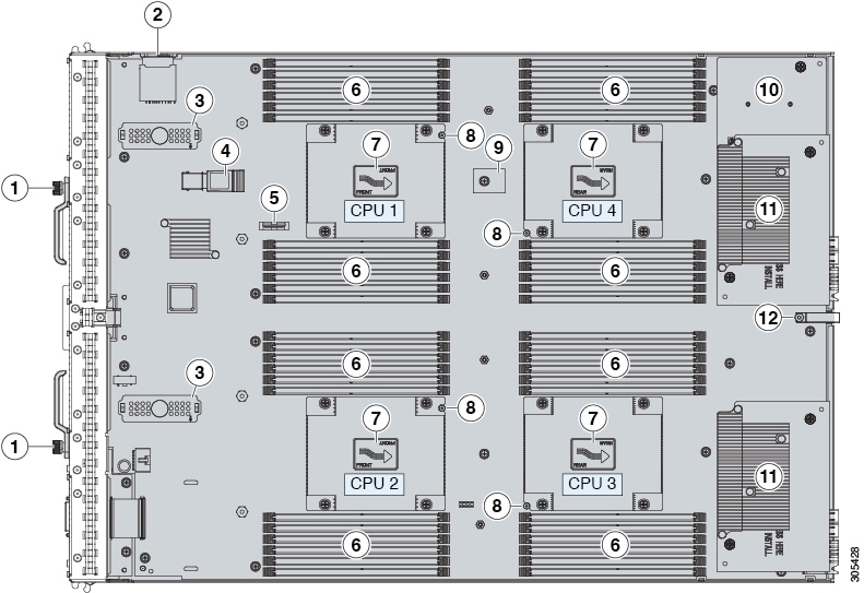
|
1 |
イジェクタ非脱落型ネジ |
7 |
ヒート シンクと CPU(下) |
|
2 |
SD カード スロット |
8 |
CPU ヒート シンク取り付けガイド ピン |
|
3 |
モジュラ ストレージ サブシステム コネクタ |
9 |
トラステッド プラットフォーム モジュール(TPM) |
|
4 |
USB メモリ |
10 |
アダプタ 1 は、Cisco VIC 1340 アダプタと Cisco VIC 1240 アダプタだけをサポートしています。 |
|
5 |
CMOS バッテリ |
11 |
|
|
6 |
DIMM スロット |
12 |
診断ボタン |
(注) |
|
ブレードの起動時に POST 診断によって CPU、DIMM、HDD、アダプタ カードがテストされ、障害があればエラー通知が UCS Manager に送信されます。通知は Cisco UCS Manager システム エラー ログまたは show tech-support コマンド出力で確認できます。エラーが検出されると、障害が発生したコンポーネントの横にある LED もオレンジに点灯します。実行時に、ブレード BIOS とコンポーネント ドライバによってハードウェアの障害がモニタされ、必要に応じてオレンジ色の診断 LED が点灯します。
LED の状態は保存され、シャーシからブレードを取り外すと、LED の値は最大 10 分間継続されます。マザーボードの診断ボタンを 30 秒間押し続けて、コンポーネントのエラーを表示します。シャーシにブレードを取り付け直して起動すると LED の障害値がリセットされ、プロセスが最初から開始されます。
DIMM 挿入エラーが検出されると、ブレードの検出プロセスが失敗する場合があり、エラーはサーバの POST 情報でレポートされます。これは、UCS Manager GUI または CLI から確認できます。特定の規則に従って DIMM が装着されている必要があります。このルールはブレード サーバのモデルによって異なります。DIMM の装着ルールについては、『Cisco UCS B420 M4 Blade Server Specification Sheet』を参照してください。
DIMM またはアダプタ カードで障害が発生すると、サーバの状態 LED は、軽微な障害ではオレンジに点灯し、重大な障害ではオレンジに点滅します。
すべての Cisco UCS ブレード サーバは、電源がオンになっているシャーシに装着されていない場合は、CR2032 バッテリを使用して BIOS 設定を保持します。シスコは、ほとんどの電子機器販売店で販売されている業界標準の CR2032 バッテリをサポートしています。
 警告 |
バッテリを正しく交換しないと、爆発するおそれがあります。Replace the battery only with the same or equivalent type recommended by the manufacturer. Dispose of used batteries according to the manufacturer’s instructions. |
バッテリの取り付けまたは交換を行うには、次の手順に従います。
| ステップ 1 |
既存のバッテリを取り外します。
|
| ステップ 2 |
交換用バッテリを取り付けます。 |
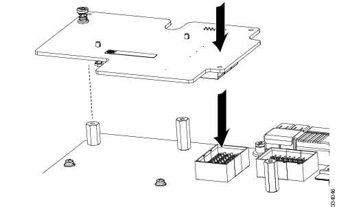
UCS B420 M4 ブレード サーバは、2 つのドライブ ベイおよび RAID コントローラのサポート機能を提供できるオプションの Cisco UCS FlexStorage のモジュラ ストレージ サブシステムを使用します。
| ステップ 1 |
モジュラ ストレージ サブシステムとマザーボードの両方のコネクタから保護カバーを取り外します。 |
| ステップ 2 |
モジュラ ストレージ サブシステム コネクタをマザーボード コネクタの上に配置し、非脱落型ネジの位置を、スタンドオフとマザーボード取り付け穴に合わせます。 |
| ステップ 3 |
モジュラ ストレージ サブシステムの「PRESS HERE TO INSTALL」というラベルの部分を、マザーボード コネクタに押し込みます。 |
| ステップ 4 |
ネジを締めます。 |
Intel Xeon E5-4600 シリーズ v4 に CPU をアップグレードする前に、次の表にリストされている、Intel E5-4600 v4 シリーズ CPU をサポートする最低限のソフトウェアおよびファームウェア バージョンがサーバで実行されていることを確認します。
|
ソフトウェアまたはファームウェア |
最小バージョン |
|---|---|
|
Cisco UCS Manager |
リリース 3.1(2) またはリリース 2.2(8) (追加のサポートされるバージョンについては、以下の注を参照してください。) |
|
Cisco IMC |
リリース 3.1(2) またはリリース 2.2(8) |
|
BIOS |
リリース 3.1(2) またはリリース 2.2(8) |
(注) |
Cisco UCS Manager リリース 2.2(4) では、サーバ パック機能が導入され、Intel E5-4600 v4 CPUs で Cisco UCS Manager リリース 2.2(4) 以降を実行できます(Cisco IMC、BIOS、および機能カタログで、すべて リリース 2.2(8) 以降が実行されている場合)。 |
注意 |
Intel E5-4600 v4 Series CPU を取り付ける前に、必要なソフトウェアおよびファームウェアがサーバで実行されていることを確認してください。そうしないと、CPU が起動できない場合があります。 |
次のいずれか 1 つの処理を実行します。
サーバのソフトウェアやファームウェアが必要な最小限のバージョンでない場合は、『Cisco UCS B420 M4 Server Upgrade Guide for E5-4600 v4 Series CPUs』の手順に従ってアップグレードしてください。その後、次のセクションの手順を使用することによって CPU を交換します。
| ステップ 1 |
4 本の非脱落型ネジを緩めます。 |
| ステップ 2 |
ヒート シンクを取り外します。 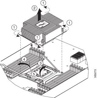 |
| ステップ 3 |
ロック解除アイコン |
| ステップ 4 |
ロック アイコン This image 331733_2.jpg is not available in preview/cisco.com がある SLS レバーをロック解除します。 |
| ステップ 5 |
(図の矢印で示すように)CPU キャリアの両側を持ち、SLS プラグ シートに立たせます。 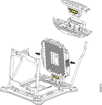 |
| ステップ 6 |
CPU キャリアを上に引っ張り SLS プラグ シートから抜き出します。 |
サーバに新しい CPU を取り付ける前に、次の点を確認してください。
CPU と特定のサーバの設定をサポートする BIOS アップデートが存在し、インストール済みである。
Cisco UCS Manager で新しい Cisco CPU がそのサーバ用のサービス プロファイルによって認識および使用可能である。
| ステップ 1 |
CPU キャリアを両側から保持します(矢印で示すように)。2 つの CPU キャリアのペグを自動ロード ソケット(SLS)のプラグ シートに挿入し位置を調整します。適切な位置に配置されるように、ALIGN の文字の下にある黄色の横線が水平であることを確認します。 |
| ステップ 2 |
カチッと音がするまで外側から CPU キャリアの上部をゆっくり押し込みます。 |
| ステップ 3 |
ソケット ラッチを閉じます。 |
| ステップ 4 |
ロック アイコン |
| ステップ 5 |
ロック解除アイコン This image 331732_2.jpg is not available in preview/cisco.com がある SLS レバーを固定します。 |
| ステップ 6 |
CPUとヒートシンクをサーマルボンディングします。交換用の CPU に付属のサーマル グリスのシリンジを使用して、2 立方センチメートルのサーマル グリスをヒート シンクと接触する CPU の上部に追加します。次の図に示すパターンでグリスを塗ります。これにより、シリンジの内容物の約半分が消費されます。 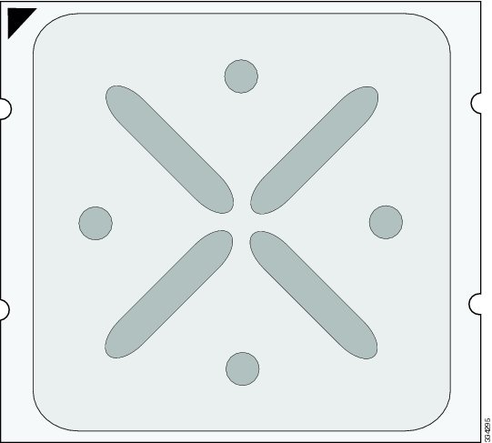 |
| ステップ 7 |
ヒート シンクを設置します。マザーボードに取り付けられる黄色の CPU ヒート シンク取り付けガイド ピンは、ヒート シンクの切り欠き部を使用して調整し、ヒート シンクが適切に取り付けられるようにする必要があります。 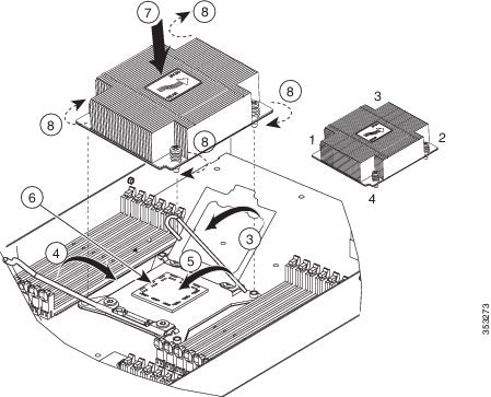 |
| ステップ 8 |
図に示す順序で 4 本の非脱落型ネジを締めます。 |
ブレード サーバに DIMM を取り付けるには、次の手順を実行します。
| ステップ 1 |
カチッという音がするまで、両端が均等になるようにして DIMM をスロットに押し込みます。 DIMM には正しい取り付け方向があります。通常の力で DIMM がソケットに収まらない場合は、DIMM のノッチの位置がスロット側と一致しているかどうかを確認します。
|
||
| ステップ 2 |
DIMM コネクタ ラッチを内側に少し押して、ラッチを完全にかけます。 |
このブレード サーバでサポートされる DIMM は定期的に更新されます。現在サポートされていて利用可能な DIMM は、『Cisco UCS B420 M4 Blade Server Specification Sheet』に記載されています。
スペック シートに記載されている DIMM 以外のメモリ DIMM は使用しないでください。これらを使用すると、サーバに修復不可能な損傷を与え、ダウンタイムが必要になる場合があります。
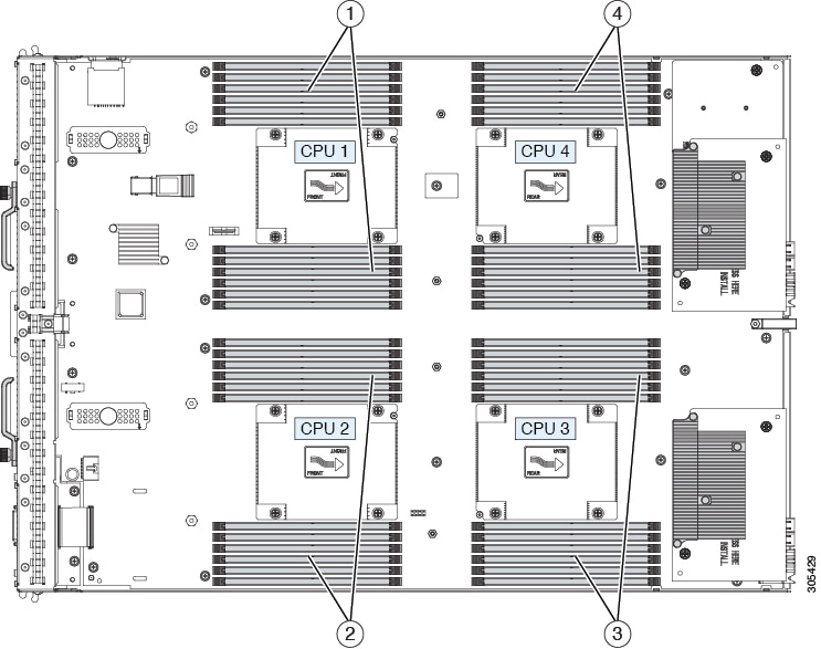
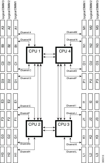
Cisco UCS B420 の高性能ブレード サーバには、DIMM を取り付けるための 48 個のスロット(各 CPU に 12 個)があります。各 CPU では 12 個の DIMM スロットが 4 チャネルに分散しています。このブレード サーバでは、すべての装着された CPU に少なくとも 1 個の DIMM が接続されている必要があります。CPU が不在のスロットに取り付けられた DIMM は認識されません。最適なパフォーマンスを得るには、すべての CPU に DIMM を均等に分散させます。DIMM コネクタ ラッチは青、黒、および白に色分けされており、この順序で DIMM を取り付ける必要があります。
|
1 |
CPU 1 の DIMM |
3 |
CPU 3 の DIMM |
|
2 |
CPU 2 の DIMM |
4 |
CPU 4 の DIMM |
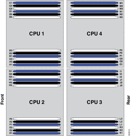
各 CPU には 4 個のチャネルがあり、3 つの DIMM で構成されています。各チャネルは 1 文字で識別されます。各チャネル メンバは、1、2、または 3 の番号によって識別されます。
DIMM スロットは、それぞれの関連する CPU に隣接しています。DIMM を取り付けるときは、次の表に示す構成で追加する必要があります。
|
CPU 単位での DIMM |
CPU 1 スロット の装着 |
CPU 2 スロット の装着 |
CPU 3 スロット の装着 |
CPU 4 スロット の装着 |
カラー コーディング |
|---|---|---|---|---|---|
|
1 |
A1 |
E1 |
I1 |
M1 |
青色 |
|
2 |
A1、B1 |
E1、F1 |
I1、J1 |
M1、N1 |
青色 |
|
3 |
A1、B1、C1 |
E1、F1、G1 |
I1、J1、K1 |
M1、N1、O1 |
青色 |
|
4 |
A1、B1、C1、D1 |
E1、F1、G1、H1 |
I1、J1、K1、L1 |
M1、N1、O1、P1 |
青色 |
|
5 |
パフォーマンス上の理由から推奨されません。 |
||||
|
6 |
A1、B1、C1、 A2、B2、C2 |
E1、F1、G1、 E2、F2、G2 |
I1、J1、K1、 I2、J2、K2 |
M1、N1、O1、M2、N2、O2 |
青、黒 |
|
7 |
パフォーマンス上の理由から推奨されません。 |
||||
|
8 |
A1、B1、C1、D1, A2、B2、C2、D2 |
E1、F1、G1、H1、E2、F2、G2、H2 |
I1、J1、K1、L1、I2、J2、K2、L2 |
M1、N1、O1、P1、M2、N2、O2、P2 |
青、黒 |
|
9 |
A1、B1、C1、 A2、B2、C2、 A3、B3、C3 |
E1、F1、G1、 E2、F2、G2、 E3、F3、G3 |
I1、J1、K1、 I2、J2、K2、 I3、J3、K3 |
M1、N1、O1、 M2、N2、O2、 M3、N3、O3 |
青、黒、白 |
|
10 |
パフォーマンス上の理由から推奨されません。 |
||||
|
11 |
パフォーマンス上の理由から推奨されません。 |
||||
|
12 |
A1、B1、C1、D1, A2、B2、C2、D2, A3、B3、C3、D3 |
E1、F1、G1、H1、E2、F2、G2、H2、E3、F3、G3、H3 |
I1、J1、K1、L1、I2、J2、K2、L2、I3、J3、K3、L3 |
M1、N1、O1、P1、M2 N2、O2、P2、M3、N3、O3、P3 |
青、黒、白 |
サーバを設定する際には、次のことを考慮します。
ブレード内の DIMM はさまざまな速度で使用できますが、すべての DIMM は、最も低速の DIMM の速度で動作します。
DIMM タイプ(LRDIMM、RDIMM、TSV-RDIMM)の混在はできません。
CPU の選択によっては、パフォーマンスに影響を及ぼす場合があります。使用する CPU は同じタイプにする必要があります。
ランクおよび密度の異なる DIMM を混在させた場合、パフォーマンスが低下することがあります。
DIMM の装着状態が CPU 間で揃っていない場合、パフォーマンスが低下することがあります。
(注) |
これを扱う作業では、アダプタ カードを取り外す必要があります。 |
ブレード サーバに Cisco VIC 1340 または VIC 1240 を取り付けるには、次の手順を実行します。
| ステップ 1 |
VIC のボードを、コネクタがマザーボードのコネクタの上にくるように保持し、非脱落型ネジをマザーボード上のスタンドオフ ポストの位置に合わせます。 |
||
| ステップ 2 |
VIC のボードのコネクタをマザーボードのコネクタにしっかりと押し込みます。 |
||
| ステップ 3 |
非脱落型ネジを締めます。
 |
ネットワーク アダプタとインターフェイス カードは、すべて同じ取り付け手順に従います。これらのカードは頻繁に更新されます。現在サポートされていてこのサーバに対して使用可能なモデルは、次の URL の仕様シートに記載されています。
http://www.cisco.com/en/US/products/ps10280/products_data_sheets_list.html [英語]
アダプタ スロット 1(4 × 10 Gb)は、VIC 1340 または VIC 1240 アダプタ用スロットです。他のアダプタ カードをスロット 1 に装着することはできません。
アダプタ スロット 2(4 × 10 Gb)は、VIC ポート エクスパンダ カードまたはストレージ アクセラレータ カード用スロットです。ポート エクスパンダは、VIC 1340 または VIC 1240 が装着されている場合にだけ使用できます。
アダプタ スロット 3(8 × 10 Gb)は、VIC 1380 または VIC 1280 アダプタまたはストレージ アクセラレータ カード用スロットです。
VIC 1340 および VIC 1380 アダプタには Cisco UCS 6200 シリーズ ファブリック インターコネクトまたは Cisco UCS 6300 シリーズ ファブリック インターコネクトが必要で、Cisco Nexus 2208XP、2204XP、2348UPQ Fabric Extender(FEX)モジュールをサポートしています。
VIC 1240 および VIC 1280 アダプタは、Cisco UCS 6100、6200 および 6300 シリーズ ファブリック インターコネクトをサポートしており、また Cisco Nexus 2104XP、2204XP、2208XP および 2304XP FEX モジュールをサポートしています。
あるタイプのアダプタ カードを別のタイプのアダプタ カードに切り替える場合は、アダプタを物理的に切り替える前に、最新のデバイス ドライバをダウンロードして、サーバのオペレーティング システムにロードしてください。詳細については、該当する『Cisco UCS Manager Software Configuration Guide』の「Firmware Management」の章を参照してください。
| ステップ 1 |
アダプタ ボードをコネクタがマザーボードのコネクタの上にくるように保持し、アダプタの 2 本の非脱落型ネジをマザーボード上のスタンドオフ ポストの位置に合わせます(番号 1)。 |
| ステップ 2 |
アダプタのコネクタをマザーボードのコネクタにしっかりと押し込みます(番号 2)。 |
| ステップ 3 |
非脱落型ネジを締めます(番号 3)。 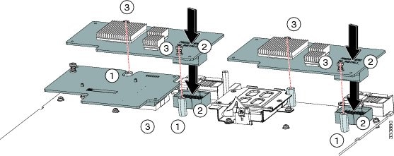 |
トラステッド プラットフォーム モジュール(TPM)は、サーバの認証に使用するアーティファクトを安全に保存できるコンポーネントです。これらのアーティファクトには、パスワード、証明書、または暗号キーを収録できます。プラットフォームが信頼性を維持していることを確認するうえで効果的なプラットフォームの尺度の保存でも、TPM を使用できます。すべての環境で安全なコンピューティングを実現するうえで、認証(プラットフォームがその表明どおりのものであることを証明すること)および立証(プラットフォームが信頼でき、セキュリティを維持していることを証明するプロセス)は必須の手順です。これは Intel の Trusted Execution Technology(TXT)セキュリティ機能の要件であり、TPM を搭載したサーバの BIOS 設定で有効にする必要があります。
| ステップ 1 |
TPM のハードウェアを取り付けます。
|
||||
| ステップ 2 |
BIOS での TPM サポートをイネーブルにします。 TPM サポートが何らかの理由で無効になっていた場合に有効にするには、次の手順を実行します。 |
||||
| ステップ 3 |
BIOS ポリシーでの TXT サポートの有効化 サーバ上で実行するリリースの『Cisco UCS Manager Configuration Guide』の手順に従ってください。 |
 Feedback