セルラー プラガブル インターフェイス モジュール(PIM)の設定

この章は、次の項で構成されています。

はじめる前に


重要


この設定ガイドは複数の製品をサポートしており、可能な限り汎用的に記述されています。このドキュメント全体で、コントローラはスロット という一般的な用語で言及されます。このガイドでは、スロットx/x/x の形式をとります。 特定のルータ/プラガブルでコントローラを設定する場合は、製品のドキュメントまたは以下の表に記載されている情報を使用してください。

サポートされているアンテナとアクセサリの詳細については、『Cisco Industrial Routers and Industrial Wireless Access Points Antenna Guide』を参照してください。


(注)  


セルラー接続にプロファイル 2 ~ 14 のいずれかを使用する場合は、セルラープロファイル 1 および 15 のアクセスポイント名(APN)を設定する必要があります。

マルチ PDN コンテキスト

この機能は、ルータが複数(現行では 2 つ)のパケットデータネットワークに接続することを可能にします。これにより、ユーザは各 PDN ごとにそれぞれ別々の機能を有効とすることができます。たとえば、1 番目の PDN をパブリック インターネット接続向けに使用し、2 番目の PDN を VPN 接続向けに使用することができます。各 PDN には、IP アドレスと QoS 特性を個別に保持させることができます。この構成は、単一のモバイルキャリアの SIM サブスクリプションおよびサービスプランでデュアル PDN がサポートされていることを前提としています。

ルータの初期化の際に、2 つの PDN に対応する 2 つのセルラー インターフェイスが作成されます。

  • cellular 0/x/0

  • cellular 0/x/1

これらのインターフェイスは、同じ無線リソースを使用して、2 つの論理インターフェイスとして表示できます。このガイドの残りの部分では、cellular 0/x/0 インターフェイスを 1 番目の PDN と呼び、cellular 0/x/1 を 2 番目の PDN と呼びます。

2 つの PDN を用意する上で、まず最初の手順として、同時に 2 つのデータ コールを発信するための設定を、セルラー インターフェイスと関連する回線の両方に適用します。

次に、データ ベアラーのプロファイルを、対応するセルラー インターフェイスまたは PDN に関連付けます。この設定は、コントローラ セルラー コンフィギュレーションで、1 番目の PDN にプロファイルを関連付けるだけです。2 番目の PDN のプロファイルは、1 番目の PDN に使用されるプロファイルの 1 つ上のプロファイルとなりますので、注意してください。たとえば、1 番目の PDN がプロファイル 1 を使用する場合、2 番目の PDN にコールが開始されると、2 番目の PDN は自動的にプロファイル 2 を使用します。

対象トラフィックがこれらのセルラーインターフェイス経由でルーティングされた後、データコールが開始され、各インターフェイスには、携帯電話ネットワークによりそれぞれ個別の IP アドレスと DNS アドレスが割り当てられます。なお、両 PDN が無線リソースを共有する点に注意してください。つまり、スループットを測定する際には、どちらか片方ではなく、両方の PDN の合計のスループットを考慮する必要があります。

ルータ セルラー アーキテクチャ

プラガブルがデュアル SIM をサポートしている場合、SIM の番号は常に 0/1 であり、プラガブルがシングル SIM(P-LTE-VZ)である場合は 0 です。

使用される設定コマンドは、controller cellularinterface cellular です。

  • Controller cellular:LTE に関連するすべてのパラメータを設定します。

  • Interface cellular:IPv4、IPv6、dialer-xxx などのインターフェイス(PDN ではない)に関連するすべてのパラメータを設定します。


    (注)  


    コントローラとインターフェイスの番号付け方式は同じです。

次の表は、これらの関係について説明しています。

ルータ

コントローラ/インターフェイス

スロット

ESR6300

0/3/0

0/3(インタグレータまでの位置)

IR1101 シリーズ

0/1/x

ベースユニット

0/3/x

拡張モジュール上(EM)側

0/4/x

拡張モジュール下(CM)側

IR1800 シリーズ

0/4/x

0/4(左側)

0/5/x

0/5(右側)

IR8100 シリーズ

0/2/x

スロットの設定によって異なります。『Cisco Catalyst IR8140 Heavy Duty Router Installation Guide』を参照してください。

0/3/x

スロットの設定によって異なります。『Cisco Catalyst IR8140 Heavy Duty Router Installation Guide』を参照してください。

IR8300 シリーズ

0/4/x

左側

0/5/x

右側

ISR1000 シリーズ

0/2/x

背面側右

Catalyst 8200 シリーズ

0/2/x

背面側中央

Catalyst 8300 シリーズ

0/2/x

モジュールと設定によって異なります。『Hardware Installation Guide for Cisco Catalyst 8300 Series Edge Platforms』を参照してください。

0/3/x

モジュールと設定によって異なります。『Hardware Installation Guide for Cisco Catalyst 8300 Series Edge Platforms』を参照してください。

Catalyst 8200 UCPE

0/2/x

背面側中央

モデム信号強度およびサービス可用性の確認

手順

  コマンドまたはアクション 目的

ステップ 1

show cellular slot network

例:

Router# show cellular x/x/x network

通信事業者ネットワーク、セル サイト、および使用可能なサービスに関する情報を表示します。

ステップ 2

show cellular slot radio details

例:

Router# show cellular x/x/x radio details

無線信号の強さを示します。

(注)  

 
安定した信頼性の高い接続には、RSSI が -90 dBm を超える必要があります。

ステップ 3

show cellular slot profile

例:

Router# show cellular x/x/x profile

作成されたモデム データ プロファイルに関する情報を示します。

ステップ 4

show cellular slot security

例:

Router# show cellular x/x/x security

SIM およびモデムのロック ステータスに関するセキュリティ情報を示します。

ステップ 5

show cellular slot all

例:

Router# show cellular x/x/x all

モデム、作成されたプロファイル、無線信号の強さ、ネットワーク セキュリティなどに関する統合的な情報を示します。

次に、P-LTEAP18-GL を備えた IR1101 での show cellular 0/1/0 all の出力を示します。
IR1101#show cellular 0/1/0 all
Hardware Information
====================
Modem Firmware Version = 32.00.116
Host Firmware Version = 32.00.007
Device Model ID = LM960A18
International Mobile Subscriber Identity (IMSI) = 310170205101138
International Mobile Equipment Identity (IMEI) = 356299100001310
Integrated Circuit Card ID (ICCID) = 89011702272051011382
Mobile Subscriber Integrated Services
Digital Network-Number (MSISDN) =
Modem Status = Modem Online
Current Modem Temperature = 39 deg C
PRI version = 1026, Carrier = Generic
OEM PRI version = 32101006

Profile Information
====================

Profile 1 = ACTIVE* **
--------
PDP Type = IPv4
PDP address = 10.52.50.241
IPv4 PDP Connection is successful
Access Point Name (APN) = m2m.com.attz
Authentication = None
Primary DNS address = 8.8.8.8
Secondary DNS address = 8.8.4.4

Profile 2 = INACTIVE
--------
PDP Type = IPv4
Access Point Name (APN) = m2m.com.attz
Authentication = None

Profile 3 = INACTIVE
--------
PDP Type = IPv4
Access Point Name (APN) = mmsbouygtel.com
Authentication = None

Profile 5 = INACTIVE
--------
PDP Type = IPv4
Access Point Name (APN) = orange
Authentication = None

Profile 16 = INACTIVE
--------
PDP Type = IPv4
Access Point Name (APN) = test
Authentication = None

* - Default profile
** - LTE attach profile


Configured default profile for active SIM 0 is profile 1.


Data Connection Information
===========================
Profile 1, Packet Session Status = ACTIVE
Cellular0/1/0:
Data Packets Transmitted = 26 , Received = 24
Data Transmitted = 1900 bytes, Received = 2311 bytes
IP address = 10.52.50.241
Primary DNS address = 8.8.8.8
Secondary DNS address = 8.8.4.4
Profile 2, Packet Session Status = INACTIVE
Profile 3, Packet Session Status = INACTIVE
Profile 4, Packet Session Status = INACTIVE
Profile 5, Packet Session Status = INACTIVE
Profile 6, Packet Session Status = INACTIVE
Profile 7, Packet Session Status = INACTIVE
Profile 8, Packet Session Status = INACTIVE
Profile 9, Packet Session Status = INACTIVE
Profile 10, Packet Session Status = INACTIVE
Profile 11, Packet Session Status = INACTIVE
Profile 12, Packet Session Status = INACTIVE
Profile 13, Packet Session Status = INACTIVE
Profile 14, Packet Session Status = INACTIVE
Profile 15, Packet Session Status = INACTIVE
Profile 16, Packet Session Status = INACTIVE


Network Information
===================
Current System Time = Wed Apr 27 8:48:13 2022
Current Service Status = Normal
Current Service = Packet switched
Current Roaming Status = Roaming
Network Selection Mode = Automatic
Network = F-Bouygues Telecom
Mobile Country Code (MCC) = 208
Mobile Network Code (MNC) = 20
Packet switch domain(PS) state = Attached
LTE Carrier Aggregation state = Deconfigured
Registration state(EMM) = Registered
EMM Sub State = Normal Service
Tracking Area Code (TAC) = 30440
Cell ID = 128697859
Negotiated network MTU = 1430

Radio Information
=================
Radio power mode = Online
LTE Rx Channel Number(PCC) = 3175
LTE Tx Channel Number(PCC) = 21175
LTE Band = 7
LTE Bandwidth = 15 MHz
Current RSSI = -60 dBm
Current RSRP = -91 dBm
Current RSRQ = -14 dB
Current SNR = 14.8 dB
Physical Cell Id = 378
Number of nearby cells = 1
Idx PCI (Physical Cell Id)
--------------------------------
1 378
Radio Access Technology(RAT) Preference = AUTO
Radio Access Technology(RAT) Selected = LTE
Network Change Event = unknown


LTE bands supported by modem:
- Bands 1 2 3 4 5 7 8 12 13 14 17 18 19 20 25 26 28 29 30 32 38 39 40 41 42 43 46 48 66 71.
LTE band Preference settings for the active sim(slot 0):
- Bands 1 2 3 4 5 7 8 12 13 14 17 18 19 20 25 26 28 29 30 32 38 39 40 41 42 43 46 48 66 71.

3G bands supported by modem:
Index:
23 - UMTS Band 1: 2100 MHz (IMT)
24 - UMTS Band 2: 1900 MHz (PCS A-F)
26 - UMTS Band 4: 1700 MHz (AWS A-F)
27 - UMTS Band 5: US 850 MHz (CLR)
50 - UMTS Band 8: 900 MHz (E-GSM)
51 - UMTS Band 9: Japan 1700 MHz
61 - UMTS Band 19: 800 MHz (800 Japan)
3G band Preference settings for the active sim(slot 0):
Index:
23 - UMTS Band 1: 2100 MHz (IMT)
24 - UMTS Band 2: 1900 MHz (PCS A-F)
26 - UMTS Band 4: 1700 MHz (AWS A-F)
27 - UMTS Band 5: US 850 MHz (CLR)
50 - UMTS Band 8: 900 MHz (E-GSM)
51 - UMTS Band 9: Japan 1700 MHz
61 - UMTS Band 19: 800 MHz (800 Japan)

===========================================

Band index reference list:

For LTE and 5G, indices 1-128 correspond to bands 1-128.

For 3G, indices 1-64 maps to the 3G bands mentioned against each above.


Modem Security Information
==========================
Active SIM = 0
SIM switchover attempts = 0
Card Holder Verification (CHV1) = Disabled
SIM Status = OK
SIM User Operation Required = None
Number of CHV1 Retries remaining = 3

Cellular Firmware List
==========================
Idx Carrier FwVersion PriVersion Status
1 Generic 32.00.116 1026 Active
2 Verizon 32.00.126 2022 Inactive
3 ATT 32.00.147 4024 Inactive
4 TMUS 32.00.156 5005 Inactive

Firmware Activation mode = MANUAL

FOTA Information
=================
FOTA Server is not configured

SMS Information
===============
Incoming Message Information
----------------------------
SMS stored in modem = 0
SMS archived since booting up = 0
Total SMS deleted since booting up = 0
Storage records allocated = 25
Storage records used = 0
Number of callbacks triggered by SMS = 0
Number of successful archive since booting up = 0
Number of failed archive since booting up = 0


Outgoing Message Information
----------------------------
Total SMS sent successfully = 0
Total SMS send failure = 0
Number of outgoing SMS pending = 0
Number of successful archive since booting up = 0
Number of failed archive since booting up = 0
Last Outgoing SMS Status = SUCCESS
Copy-to-SIM Status = 0x0
Send-to-Network Status = 0x0
Report-Outgoing-Message-Number:
Reference Number = 0
Result Code = 0x0
Diag Code = 0x0 0x0 0x0 0x0 0x0

SMS Archive URL =

Mobile app service = Not Available

Modem Crashdump Information
===========================
Modem crashdump logging = off

Dying Gasp Information
===========================
Dying Gasp Detach = Disabled
SMS = Disabled


Packet drop stats
=================

Source IP violation stats:
Total dropped IPv4 packets: 0
Recently violated IPv4 addresses (Max 4):

Total dropped IPv6 packets: 0
Recently violated IPv6 addresses (Max 4):

IR1101#

データプロファイルの使用

モバイルネットワークのカスタマイズされたプロファイル アクセス ポイント名(APN)を作成し、セルラー プラガブル モジュールで使用できます。作成できるプロファイルの最大数は 16 です。

各プロファイルは、AT&T などの特定のファームウェア用に作成されます。汎用の PTCRB といった別のファームウェアに切り替える場合は、プロファイルを作成する必要があります。SIM カードのサブスクリプションで 2 つのアクティブな PDN がサポートされている場合、cellular 0/x/0 および 0/x/1 などの各インターフェイスには、専用のプロファイルを作成する必要があります。

グローバルモードまたは設定モードを使用してプロファイルが作成されると、そのプロファイルは PIM 自体に保存されます。つまり、ルータでの設定を必要としないため、プロファイルを作成し、設定を write erase して、PnP プロセスを機能させることができます。

プロファイル設定が使用できない状況では、必要なパラメータを使用して個別のプロファイルを作成する必要があります。

モデム データ プロファイルの作成、変更、削除に関するガイドライン

EXEC モードまたは Config モードを使ったデータプロファイルの設定では、次のガイドラインに従ってください。

  • モデムにデータプロファイルが付属している場合(AT&T、Sprint、Verizon など)、プロファイル関連の変更は不要です。

  • 接続タイプ用にプロファイル パラメータの変更が必要な場合は、原則として、デフォルト プロファイル内で変更を実施します。


    (注)  


    Verizon のプライベートネットワークでは、APN などのパラメータを変更してプロファイル 3 を作成し、ATT のプロファイル 1 を作成することをお勧めします。
  • プロファイル タイプを別々に設定し、それぞれ異なる接続で使用したい場合は、APN 名などのパラメータを変えることで、別々のプロファイルを作成することが可能です。なお、一度にアクティブにできるプロファイルは 1 つだけであることに注意してください。

  • データプロファイルを表示するには、show cellular <slot> profile コマンドを使用します。データ プロファイルには、アスタリスク(*)記号が表示されます。接続プロファイルに対して二重のアスタリスク(* *)記号が表示されます。

  • データ プロファイルはデータ コールの設定に使用されます。別のプロファイルを使用したい場合、そのプロファイルをデフォルトにする必要があります。controller cellular x/x/x でデフォルトプロファイルを変更するには、lte sim data-profile <number> コマンドを使用します。

EXEC モードを使ったデータ プロファイルの作成、変更、削除

モバイルネットワークのカスタマイズされたプロファイル アクセス ポイント名(APN)を作成し、セルラー プラガブル インターフェイス モジュールで使用できます。作成できるプロファイルの最大数は 16 です。

特定のキャリア プロビジョニング ファイルを含む Cisco SKU の発送の場合、デフォルトプロファイルはすでに入力されており、すぐに展開できます。該当するプロファイルは、show cellular slot hardware コマンドのキャリアラベルにあります。

手順

コマンドまたはアクション 目的

cellular slot lte profile [create | delete] profile-number [apn [authentication [username password [bearer-type ]]]]

例:

Router# cellular x/x/x lte profile create 2 apn.com pap username pwd ipv4

特権 EXEC モードでモデム データ プロファイルを作成、変更、または削除します。

  • profile-number 引数には、モデム用に作成されたプロファイル番号を指定します。

  • (任意)apn 引数は、アクセス ポイント名(APN)を指定します。APN はサービス プロバイダーによって提供されます。1 つのプロファイルに指定できるのは 1 つの APN のみです。

  • (任意)authentication パラメータは、使用する認証タイプを指定します。許容可能なパラメータは chap、none(認証なし)、pap、および pap_chap(PAP または CHAP 認証)です。

  • (オプション)username および password 引数は、サービス プロバイダーが指定します。[none] 以外の認証タイプが使用されている場合、これらは必須です。

  • (オプション)PDN 型パラメータは、このプロファイルを使用してモバイル ネットワークで確立されたパケット データ セッションのタイプを指定します。許容可能なパラメータは、ipv4、ipv6、および ipv4v6(IPv4 および IPv6)です。

show cellular slot profile コマンドにより、設定されたプロファイルリストが表示されます。

(注)  


データ プロファイルには、アスタリスク(*)が表示されます。

接続されたプロファイルには 2 つのアスタリスク(**)が表示されます。

router# show cellular x/x/x profile 
Profile 1 = INACTIVE **
--------
PDP Type = IPv4v6
Access Point Name (APN) = vzwims
Authentication = None
 
Profile 2 = INACTIVE
--------
PDP Type = IPv4v6
Access Point Name (APN) = vzwadmin
Authentication = None
 
Profile 3 = ACTIVE*
--------
PDP Type = IPv4v6
PDP address = 100.119.136.44
PDP IPV6 address = 2600:1010:B00E:1E11:192D:3E20:199B:3A70/64  Scope: Global
Access Point Name (APN) = VZWINTERNET
Authentication = None
        Primary DNS address = 198.224.173.135
        Secondary DNS address = 198.224.174.135
        Primary DNS IPV6 address = 2001:4888:68:FF00:608:D:0:0
        Secondary DNS IPV6 address = 2001:4888:61:FF00:604:D:0:0
 
Profile 4 = INACTIVE
--------
PDP Type = IPv4v6
Access Point Name (APN) = vzwapp
Authentication = None
 
Profile 5 = INACTIVE
--------
PDP Type = IPv4v6
Access Point Name (APN) = vzw800
Authentication = None
 
Profile 6 = INACTIVE
--------
PDP Type = IPv4v6
Access Point Name (APN) = CISCO.GW4.VZWENTP
Authentication = None
 
  * - Default profile
 ** - LTE attach profile
#show cellular x/x/x profile
Profile 1 = INACTIVE **
--------
PDP Type = IPv4v6
Access Point Name (APN) = vzwims
Authentication = None

Profile 2 = INACTIVE
--------
PDP Type = IPv4v6
Access Point Name (APN) = vzwadmin
Authentication = None

Profile 3 = ACTIVE*
--------
PDP Type = IPv4v6
PDP address = 100.86.69.19
PDP IPV6 address = 2600:1010:B040:DA58:1C27:D97:321E:18C4/64  Scope: Global
Access Point Name (APN) = VZWINTERNET
Authentication = None
	Primary DNS address = 198.224.173.135
	Secondary DNS address = 198.224.174.135
	Primary DNS IPV6 address = 2001:4888:68:FF00:608:D:0:0
	Secondary DNS IPV6 address = 2001:4888:61:FF00:604:D:0:0

Profile 4 = INACTIVE
--------
PDP Type = IPv4v6
Access Point Name (APN) = vzwapp
Authentication = None

Profile 5 = INACTIVE
--------
PDP Type = IPv4v6
Access Point Name (APN) = vzw800
Authentication = None

Profile 6 = INACTIVE
--------
PDP Type = IPv4v6
Access Point Name (APN) = vzwclass6
Authentication = None

  * - Default profile 
 ** - LTE attach profile


Configured default profile for active SIM 0 is profile 3.

(注)  


データと接続プロファイルのバインディングを変更する必要がある場合は、controller cellular slot コマンドを使用します。
router(config-controller)# lte sim data-profile 3 attach-profile 2 slot slot
 
Router#show cellular x/x/x profile
Profile 1 = INACTIVE
--------------------------------------------------
PDP Type = IPv4v6
Access Point Name (APN) = test
Authentication = None
 
Profile 2 = INACTIVE **
--------
PDP Type = IPv4
Access Point Name (APN) = internet
Authentication = PAP or CHAP
Username =  user@solution.com
Password =  cisco
 
Profile 3 = INACTIVE*
--------
PDP Type = IPv4v6
Access Point Name (APN) = basic
Authentication = None
 
  * - Default profile
 ** - LTE attach profile
Configured default profile for active SIM 0 is profile 2.

設定モードを使ったデータ プロファイルの作成、変更、削除

手順

コマンドまたはアクション 目的

profile id id-number apn apn-name authentication username-password pdn-type pdn-type no-overwrite

例:

Router(config-controller) profile id 1 apn 
apn_internet authentication none pdn-type ipv4 no-overwrite

設定モードでセルラー プロファイルを設定します。

  • id 引数には、モデム用に作成されたプロファイル番号を指定します。各モデムに作成できるプロファイルの最大数は 16 です。

  • (任意)apn 引数は、プロファイル内のアクセス ポイント名(APN)を指定します。APN はサービス プロバイダーによって提供されます。1 つのプロファイルには、1 つの APN だけを指定できます。

  • (任意)authentication パラメータは、使用する認証タイプを指定します。許容可能なパラメータは、chap none (認証なし)、pap および pap_chap (PAP または CHAP 認証)です。

  • (任意)username および password 引数は、サービス プロバイダーが指定します。none 以外の認証タイプが使用されている場合、これらは必須です。

  • (任意)PDN-type パラメータは、このプロファイルを使用してモバイル ネットワークで確立されたパケット データ セッションのタイプを指定します。許容可能なパラメータは ipv4ipv6 およびipv4v6 (IPv4 と IPv6)です。

  • (任意)プロファイル id のモデムにプロファイルがすでに存在している場合に実行される No-overwrite アクション。このプロファイル id のモデムにすでにプロファイルが存在し、no-overwrite オプションが指定されている場合、この設定を行うことで既存のプロファイルは上書きされません。デフォルトの設定は overwrite です。

例:デフォルトプロファイルの変更

次の例は、デフォルトプロファイルを変更する方法を示しています。


router(config-controller)# lte sim data-profile 2 attach-profile 1 slot slot

次に、Verizon ネットワークサービスの show cellular コマンドの出力例を示します。


router# show cellular x/x/x profile 
Profile 1 = INACTIVE **
--------
PDP Type = IPv4v6
Access Point Name (APN) = vzwims
Authentication = None

Profile 2 = INACTIVE
--------
PDP Type = IPv4v6
Access Point Name (APN) = vzwadmin
Authentication = None

Profile 3 = ACTIVE*
--------
PDP Type = IPv4v6
PDP address = 100.119.136.44
PDP IPV6 address = 2600:1010:B00E:1E11:192D:3E20:199B:3A70/64  Scope: Global
Access Point Name (APN) = VZWINTERNET
Authentication = None
        Primary DNS address = 198.224.173.135
        Secondary DNS address = 198.224.174.135
        Primary DNS IPV6 address = 2001:4888:68:FF00:608:D:0:0
        Secondary DNS IPV6 address = 2001:4888:61:FF00:604:D:0:0

Profile 4 = INACTIVE
--------
PDP Type = IPv4v6
Access Point Name (APN) = vzwapp
Authentication = None

Profile 5 = INACTIVE
--------
PDP Type = IPv4v6
Access Point Name (APN) = vzw800
Authentication = None

Profile 6 = INACTIVE
--------
PDP Type = IPv4v6
Access Point Name (APN) = CISCO.GW4.VZWENTP
Authentication = None

  * - Default profile
 ** - LTE attach profile 

例:セルラープロファイルの設定

次に、セルラープロファイルでの設定例を示します。


router(config-controller)# profile id 1 apn apn_internet authentication none pdn-type ipv4 no-overwrite

コントローラ セルラーの実行コンフィギュレーション

Router #show running-config controller cellular <slot>
Building configuration...

Current configuration : 330 bytes
!
controller Cellular x/x/x
profile id 1 apn apn_internet authentication none pdn-type ipv4 no-overwrite
end


 ** This will override exec mode profile configuration
 ** If for a profile ID, configuration CLI exists, exec mode configuration cannot be performed. 

Router #show cellular <slot> profile 5
Profile 5 = INACTIVE
--------
PDP Type = IPv4
Access Point Name (APN) = apn_old
Authentication = None

TSN1#cellular <slot> lte profile create 5 apn_new
Warning: You are attempting to create Profile 5
	Profile 5 was configured through controller configuration 'profile id <profile #>'
	Please execute command under controller configuration using '[no] profile id <profile #>' for profile 5 to create
	Profile 5 NOT written to modem


** As part of this enhancement, any attach and/or data profile changes will immediately 
trigger a connection reset and take effect. Below warning message will be displayed. 

Warning: You are attempting to modify the data/attach profile.
Connection will be reset

SIM コンフィギュレーションのモデム プロファイルの適用

手順

  コマンドまたはアクション 目的

ステップ 1

configure terminal

例:

Router# configure terminal

グローバル コンフィギュレーション モードを開始します。

ステップ 2

controller cellular <slot>

例:

Router(config)# controller cellular x/x/x

セルラー コントローラ コンフィギュレーション モードを開始します。

ステップ 3

lte sim data-profile data-profile-number attach-profile number slot

設定されたプロファイル番号を SIM とそのスロット番号に適用します。デフォルト(プライマリ)スロットは 0 です。

attach profile は、携帯電話ネットワークに接続するモデムで使用されるプロファイルです。

data profile は、携帯電話ネットワークでデータの送受信に使用するプロファイルです。

スロット番号は、2 枚の異なるキャリア SIM に異なるデータを指定し、プロファイルを設定するのに役立ちます。

モデムの出荷時設定へのリセット

IOS XE リリース 17.12.1 では、設定されたプロファイルと APN を削除するためにモデムを出荷時設定にリセットする新しいコマンドが導入されました。


(注)  


LTE セルラー プロファイル クリーンアップ機能は、GENERIC ファームウェアがアクティブな場合、デュアルモデムではなく、1 つのモデムに対して機能します。

次の手順を使用します。

  1. コントローラで以下を設定します。

    controller Cellular 0/x/0
    no lte firmware auto-sim
    lte cellular-profile-cleanup
    
  2. 次のメッセージが表示されます。

    **************************************************
    Modem cellular profiles will be deleted during next reload
    if this cli is enabled and factory reset button is pressed.
    **********************************************************
    
  3. 設定を保存します。

  4. show cell 0/x/0 firmware コマンドを使用して、モデムに汎用ファームウェアがあることを確認します。


    (注)  


    モデムで汎用ファームウェアがアクティブになっている場合は、手順 5 に進む必要はなく、手順 7 に進みます。
  5. 汎用ファームウェアをアクティブにします。

    1. P-5GS6-GL モデム:

      cellular 0/x/0 lte mno-activate <mno index>
    2. その他の LTE モデム:

      cellular 0/x/0 lte firmware-activate <firmware index>
  6. show cell 0/x/0 firmware コマンドを使用して、モデムに汎用ファームウェアがあることを確認します。

  7. ルータの電源を一度オフにして、すぐにオンにします。

  8. モデムから SIM を取り外します。

  9. リセット手順を続行します(リセットボタンを押してから、電源ケーブルを差し込みます)。

  10. ルータが起動すると、次のメッセージが表示されます。

    % CELLULAR_PROFILE_CLEANUP_ON_RESET rommon variable set to FALSE successfully.
  11. ユーザーが作成したすべてのプロファイルが削除され、デフォルトのプロファイルのみが残ります。

データ呼設定

データ呼を設定するには、次の手順を実行します。

セルラーインターフェイスの設定


(注)  


完全な IP 接続を確立するには、NAT 設定が必要になる場合があります。次の例を参照してください。

セルラー インターフェイスを設定するには、EXEC モードで開始する次のコマンドを入力します。

トンネルインターフェイスが ip unnumbered cellular x/x/x で設定されている場合、ip address negotiated の代わりに、セルラーインターフェイスでの実際のスタティック IP アドレスを設定する必要があります。


(注)  


ベストプラクティスとして、トンネルにはセルラーインターフェイスの IP アドレスを使用しないでください。

手順

  コマンドまたはアクション 目的

ステップ 1

configure terminal

例:

Router# configure terminal

グローバル コンフィギュレーション モードを開始します。

ステップ 2

interface cellular slot

例:

Router(config)# interface cellular x/x/x

セルラー インターフェイスを指定します。

ステップ 3

ip address negotiated

例:

Router(config-if)# ip address negotiated

このインターフェイスの IP アドレスが動的に取得されるように設定します。

ステップ 4

dialer in-band

例:

Router(config-if)# dialer in-band

DDR を有効にし、インバンドダイヤリングを使用するよう、指定したシリアルインターフェイスを設定します。

ステップ 5

dialer watch-group <group-number>

例:

Router(config-if)# dialer watch-group 1

指定したインターフェイスが属するダイヤラ アクセス グループの番号を指定します。

ステップ 6

exit

例:

Router(config-if)# exit

グローバル コンフィギュレーション モードを開始します。

ステップ 7

ip route <network-number> <network-mask> {<ip-address> | <interface>} [<administrative distance>] [name <name> ]

例:

Router(config)# ip route 209.165.200.225 255.255.255.224 cellular x/x/x

指定されたインターフェイスを介して、設定されているアドミニストレーティブ ディスタンスを使用して、浮動スタティック ルートを確立します。

(注)  

 
プライマリ インターフェイスがダウンのときにのみ使用されるよう、バックアップ インターフェイスを介するルートに対して、より大きなアドミニストレーティブ ディスタンスを設定する必要があります。

ステップ 8

dialer-list <dialer-group> protocol <protocol-name> permit | deny | list access-list-number | access-group

例:


Router(config)# dialer-list 1 protocol ip list 1

関係するトラフィックのダイヤラ リストを作成し、プロトコル全体に対してアクセスを許可します。


unicast-routing
ipv6
interface Cellular0/2/0
ip address negotiated
ip nat outside  
dialer in-band
dialer idle-timeout 0  
dialer watch-group 1
ipv6 enable
no shutdown

interface GigabitEthernet0/0/0
 ip address 192.168.60.1 255.255.255.0
 ip nat inside
 ipv6 address autoconfig

ip nat inside source list 1 interface Cellular0/1/0 overload
ip route 0.0.0.0 0.0.0.0 Cellular0/1/0
ipv6 route ::/0 Cellular0/1/0
 
ip access-list standard 1
 10 permit 192.168.60.0 0.0.0.255
dialer watch-list 1 ip 5.6.7.8 255.255.255.255
dialer-list 1 protocol ip permit

ダイヤラウォッチグループを使用したセルラーインターフェイスの設定

ダイヤラウォッチグループを使用すると、IP アドレスとマスクに基づいてルートのグループを定義し、そのグループをグループ番号に割り当てることができます。該当するネットワークへのルートがルーティングテーブルにない場合、ルータはバックアップ接続にダイヤルします。

ダイヤラ ウォッチ グループでセルラー インターフェイスを設定するには、EXEC モードで開始する次のコマンドを入力します。

手順

  コマンドまたはアクション 目的

ステップ 1

configure terminal

例:

Router# configure terminal

グローバル コンフィギュレーション モードを開始します。

ステップ 2

interface cellular slot

例:

Router(config)# interface cellular x/x/x

セルラー インターフェイスを指定します。

ステップ 3

ip address negotiated

例:

Router(config-if)# ip address negotiated

このインターフェイスの IP アドレスが動的に取得されるように設定します。

ステップ 4

dialer in-band

例:

Router(config-if)# dialer in-band

DDR を有効にし、インバンドダイヤリングを使用するよう、指定したシリアルインターフェイスを設定します。

ステップ 5

ip address negotiated

例:

Router(config-if)# ip address negotiated

このインターフェイスの IP アドレスが動的に取得されるように設定します。

ステップ 6

dialer idle-timeout <seconds>

例:

Router(config-if)# dialer idle-timeout 30

回線にアウトバンド トラフィックがなくなった後のアイドル時間の長さを秒単位で指定します。「0」秒は、アイドル タイムアウトがないことを意味します。アイドル タイマーが指定されていない場合、デフォルトのアイドル タイムアウトは 120 秒です。

ステップ 7

dialer watch-group <group-number>

例:

Router(config-if)# dialer watch-group 1

インターフェイスでダイヤラ ウォッチを有効にします。

ステップ 8

exit

例:

Router(config-if)# exit

グローバル コンフィギュレーション モードを開始します。

ステップ 9

dialer-list <dialer-group> protocol <protocol-name> {permit | deny | list} <access-list-number> <group-number>

例:

Router(config)# dialer-list 1 protocol ip list 1

関係するトラフィックのダイヤラ リストを作成し、プロトコル全体に対してアクセスを許可します。

ステップ 10

access-list <access-list-number> permit <ip-source-address>

例:

Router(config)# access-list 1 permit any

関係するトラフィックを定義します。

ステップ 11

dialer watch-list <watch-group number> <ip> <ip mask>

例:

Router(config)# dialer watch-list 1 ip 5.6.7.8 255.255.255.255

関係するトラフィックを定義します。

ステップ 12

dialer watch-list <watch-group number> delay route-check initial <time in seconds>

例:

Router(config)# dialer watch-list 1 delay route-check initial 60

関係するトラフィックを定義します。

ステップ 13

dialer watch-list <watch-group number> delay connected <seconds>

例:

Router(config)# dialer watch-list 1 delay connect 1

関係するトラフィックを定義します。

キャリア アグリゲーション

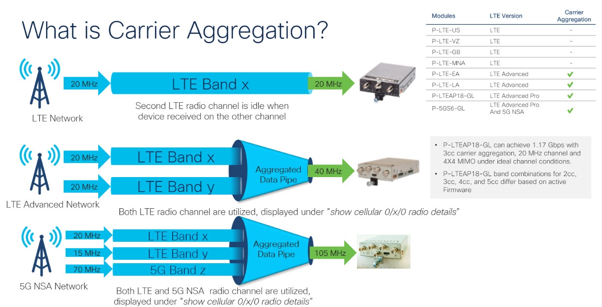
キャリアアグリゲーションを使用すると、キャリアは、単一の「集約データパイプ」経由で、複数のネットワークバンドを使用してワイヤレスルータなどのデバイスに一度にデータを送信できます。キャリアアグリゲーションを備えた LTE Advanced は複数の周波数帯域を同時に使用し、デバイスはわずか数ミリ秒で周波数帯域を切り替えることができます。さらに、1 つの帯域が切断されても、デバイスは集約データパイプの 2 番目の帯域を介して接続を維持します。

例として次の図を参照してください。

図 1. キャリア アグリゲーション

キャリアアグリゲーションは、show cellular 0/x/0 radio details コマンドを使用して監視できます。

IR1821#show cell 0/4/0 radio details
 Modem Radio is Online
 Main Antenna details:
 RSSI = -51 dBm
 RSRP = 75 dBm
 Diversity Antenna details:
 RSSI = -54 dBm
 RSRP = 81 dBm
 SCC information available
 SCC[0]:
 PCI = 27
 State = Deactivated
 Band = 3
 Rx Channel Number = 1850
 Bandwidth = 20 MHz
 SCC[1]:
 PCI = 27
 State = Deactivated
 Band = 1
 Rx Channel Number = 251
 Bandwidth = 10 MHz
 SCC[2]:
 PCI = 27
 State = Deactivated
 Band = 7
 Rx Channel Number = 3175
 Bandwidth = 15 MHz
 SCC[3]: Not Available

PCC CA information:
 LTE band class = Band 20
 E-UTRA absolute radio frequency channel number of the serving cell = 6200
 Bandwidth = 10 MHz
 Physical Cell Id = 27
 Current RSRP in 1/10 dBm as measured by L1 = -75
 Current RSSI in 1/10 dBm as measured by L1 = -49
 Current RSRQ in 1/10 dBm as measured by L1 = -10
 Measured SINR in dB = 136
 Tracking area code information for LTE = 30440

 SCC 0 CA information:
 LTE band class = Band 3
 E-UTRA absolute radio frequency channel number of the serving cell = 1850
 Bandwidth = 20 MHz
 Physical Cell Id = 27
 Current RSRP in 1/10 dBm as measured by L1 = -89
 Current RSSI in 1/10 dBm as measured by L1 = -64
 Current RSRQ in 1/10 dBm as measured by L1 = -5
 Measured SINR in dB = 0
 Current SCC state = Configured

例:キャリアアグリゲーションの表示

以下は IR1101 の例で、4G/LTE と 5G NSA 両方のキャリアアグリゲーション(CA)を示しています。

まず show cellular 0/1/0 all で、無線セクションに、コントロールプレーンにも使用されるプライマリチャネルの詳細のみが含まれていることに注目してください。

Router#show cell 0/1/0 all
Hardware Information
====================
Modem Firmware Version = M0H.030200-B012
Host Firmware Version = A0H.000300-B012
Device Model ID =  FN980
International Mobile Subscriber Identity (IMSI) = 208018903906177
International Mobile Equipment Identity (IMEI) = 359661100035944
Integrated Circuit Card ID (ICCID) = 89330120410034176680
Mobile Subscriber Integrated Services
Digital Network-Number (MSISDN) = 
Modem Status = Modem Online
Current Modem Temperature = 42 deg C
PRI version = 0880-109, Carrier = Generic GCF
OEM PRI version = 0880-109

Profile Information
====================

Profile 1 = ACTIVE* **
--------
PDP Type = IPv4
PDP address = 10.44.198.163
IPv4 PDP Connection is successful
Access Point Name (APN) = orange
Authentication = None
       Primary DNS address = 192.168.10.110

Profile 2 = INACTIVE
--------
PDP Type = IPv4v6
Access Point Name (APN) = ims
Authentication = None

Profile 15 = INACTIVE
--------
PDP Type = IPv4
Access Point Name (APN) = Broadband
Authentication = None

  * - Default profile 
 ** - LTE attach profile


Configured default profile for active SIM 0 is profile 1.

Data Connection Information
===========================
Profile 1, Packet Session Status = ACTIVE
       Cellular0/1/0:
       Data Packets Transmitted = 9249463 ,  Received = 9382548 
       Data Transmitted = 2289007661 bytes, Received = 3415239855 bytes
        IP address = 10.44.198.163
       Primary DNS address = 192.168.10.110
Profile 2, Packet Session Status = INACTIVE
Profile 3, Packet Session Status = INACTIVE
Profile 4, Packet Session Status = INACTIVE
Profile 5, Packet Session Status = INACTIVE
Profile 6, Packet Session Status = INACTIVE
Profile 7, Packet Session Status = INACTIVE
Profile 8, Packet Session Status = INACTIVE
Profile 9, Packet Session Status = INACTIVE
Profile 10, Packet Session Status = INACTIVE
Profile 11, Packet Session Status = INACTIVE
Profile 12, Packet Session Status = INACTIVE
Profile 13, Packet Session Status = INACTIVE
Profile 14, Packet Session Status = INACTIVE
Profile 15, Packet Session Status = INACTIVE
Profile 16, Packet Session Status = INACTIVE

Network Information
===================
Current System Time = Wed Apr 20 12:29:50 2022
Current Service Status = Normal
Current Service = Packet switched
Current Roaming Status = Home
Network Selection Mode = Automatic
Network = Orange F
Mobile Country Code (MCC) = 208
Mobile Network Code (MNC) = 1
Packet switch domain(PS) state = Attached
Registration state(EMM) = Registered
EMM Sub State = Normal Service
Tracking Area Code (TAC) = 50443
Cell ID = 24246021
Negotiated network MTU = 1500

Radio Information
=================
Radio power mode = Online
LTE Rx Channel Number(PCC) =  6400
LTE Tx Channel Number(PCC) =  24400
LTE Band =  20
LTE Bandwidth = 10 MHz
Current RSSI = -57 dBm
Current RSRP = -87 dBm
Current RSRQ = -13 dB
Current SNR = 13.2  dB
Physical Cell Id = 48
Number of nearby cells = 2
Idx      PCI (Physical Cell Id)
--------------------------------
1              48
2              242
Radio Access Technology(RAT) Preference = AUTO 
Radio Access Technology(RAT) Selected = LTE
Network Change Event = activated 5G ENDC


LTE bands supported by modem:
- Bands 1 2 3 4 5 7 8 12 13 14 17 18 19 20 25 26 28 29 30 32 34 38 39 40 41 42 43 46 48 66 71.
LTE band Preference settings for the active sim(slot 0):
- Bands 1 2 3 4 5 7 8 12 13 14 17 18 19 20 25 26 28 29 30 32 34 38 39 40 41 42 43 46 48 66 71.

NR5G bands supported by modem:
- Bands 1 2 3 5 7 8 12 20 25 28 38 40 41 48 66 71 77 78 79.
NR5G band Preference settings for the active sim(slot 0):
- Bands 1 2 3 5 7 8 12 20 25 28 38 40 41 48 66 71 77 78 79.

3G bands supported by modem:
Index:
  23 - UMTS Band 1: 2100 MHz (IMT)
  24 - UMTS Band 2: 1900 MHz (PCS A-F)
  26 - UMTS Band 4: 1700 MHz (AWS A-F)
  27 - UMTS Band 5: US 850 MHz  (CLR)
  50 - UMTS Band 8: 900 MHz  (E-GSM)
  51 - UMTS Band 9: Japan 1700 MHz
  61 - UMTS Band 19: 800 MHz (800 Japan)
3G band Preference settings for the active sim(slot 0):
Index:
  23 - UMTS Band 1: 2100 MHz (IMT)
  24 - UMTS Band 2: 1900 MHz (PCS A-F)
  26 - UMTS Band 4: 1700 MHz (AWS A-F)
  27 - UMTS Band 5: US 850 MHz  (CLR)
  50 - UMTS Band 8: 900 MHz  (E-GSM)
  51 - UMTS Band 9: Japan 1700 MHz
  61 - UMTS Band 19: 800 MHz (800 Japan)

===========================================

Band index reference list:

For LTE and 5G, indices 1-128 correspond to bands 1-128.

For 3G, indices 1-64 maps to the 3G bands mentioned against each above.


Modem Security Information
==========================
Active SIM = 0
SIM switchover attempts = 0
Card Holder Verification (CHV1) = Disabled
SIM Status = OK
SIM User Operation Required = None
Number of CHV1 Retries remaining = 3

Cellular Firmware List
==========================
 Idx Carrier              FwVersion        PriVersion   Status  
 1   Generic GCF          M0H.030200-B012  0880         Active  

Firmware Activation mode  =  MANUAL

Modem image running: Main
Mobile Network Operator: Generic GCF
Number of MNO's = 14
 Index MNO ID  MNO NAME
 1     0       Generic GCF
 2     1       Generic PTCRB
 3     10      AT&T
 4     11      T-Mobile
 5     12      Verizon Wireless
 6     14      Bell
 7     15      Rogers
 8     16      Telus
 9     20      SK Telecom
 10    21      SK Telecom Dongle
 11    30      NTT Docomo
 12    31      KDDI
 13    40      Telstra
 14    50      Anatel

FOTA Information
=================
FOTA Server is not configured

GPS Information
==========================
GPS Feature =  enabled
GPS Mode Configured =  standalone
GPS Port Selected =  Dedicated GPS port
GPS Status =  GPS acquiring
Last Location Fix Error =  Offline [0x0]
Latitude =  0 Deg 0 Min 0 Sec North
Longitude =  0 Deg 0 Min 0 Sec East
Timestamp (GMT) =  Sun Jan  6 00:00:00 1980

Fix type =  2D, Height =  0 m
HDOP =  , GPS Mode Used =  not configured

Satellite Info
----------------

SMS Information
===============
Incoming Message Information
----------------------------
SMS stored in modem = 1
SMS archived since booting up = 0
Total SMS deleted since booting up = 0
Storage records allocated = 25
Storage records used = 1
Number of callbacks triggered by SMS = 0
Number of successful archive since booting up = 0
Number of failed archive since booting up = 0

Outgoing Message Information
----------------------------
Total SMS sent successfully = 0
Total SMS send failure = 0
Number of outgoing SMS pending = 0
Number of successful archive since booting up = 0
Number of failed archive since booting up = 0
Last Outgoing SMS Status = SUCCESS
Copy-to-SIM Status =     0x0
Send-to-Network Status = 0x0
Report-Outgoing-Message-Number:
  Reference Number =     0
  Result Code =          0x0
  Diag Code =            0x0 0x0 0x0 0x0 0x0

SMS Archive URL = 

Mobile app service = Not Available

Modem Crashdump Information
===========================
Modem crashdump logging = off

Dying Gasp Information
===========================
 Dying Gasp Detach =  Disabled
 SMS =  Disabled


Packet drop stats
=================

Source IP violation stats:
 Total dropped IPv4 packets: 0
 Recently violated IPv4 addresses (Max 4):

 Total dropped IPv6 packets: 0
 Recently violated IPv6 addresses (Max 4):
#Router

次に、show cellular 0/1/0 radio details により、4G/LTE と 5G NSA(ENDC)両方のすべてのセカンダリチャネル(SCC)が表示されます。各チャネルには、その帯域とチャネル帯域幅が表示されます。たとえば、5G チャネルには帯域 n78 および帯域幅 90 MHz と表示され、無線信号の品質も表示されます。

Router#show cell 0/1/0 radio details
 Modem Radio is Online
 Main 0 Antenna details:
 RSSI = -57 dBm
 RSRP = 87 dBm
 Diversity 0 Antenna details:
 RSSI = -59 dBm
 RSRP = 89 dBm

 SCC information available
 SCC[0]:
 PCI = 48
 State = Deactivated
 Band = 3
 Rx Channel Number = 1300
 Bandwidth = 20 MHz
 SCC[1]:
 PCI = 48
 State = Deactivated
 Band = 7
 Rx Channel Number = 3000
 Bandwidth = 20 MHz
 SCC[2]:
 PCI = 48
 State = Deactivated
 Band = 1
 Rx Channel Number = 524
 Bandwidth = 15 MHz
 SCC[3]: Not Available

 5G CC information:
 ENDC active band = 78
 ENDC Bandwidth (MHz) = 90
 ENDC active downlink channel = 650400
 ENDC active uplink channel = 650400
 ENDC Physical Cell Id = 99
 Current ENDC RSRP in 1/10 dBm as measured by L1 = -111
 Current ENDC RSSI in 1/10 dBm as measured by L1 = -100
 Current ENDC RSRQ in 1/10 dBm as measured by L1 = -11
 Measured ENDC SINR in dB = 95

PCC CA information:
 LTE band class = Band 20
 E-UTRA absolute radio frequency channel number of the serving cell = 6400
 Bandwidth = 10 MHz
 Physical Cell Id = 48
 Current RSRP in 1/10 dBm as measured by L1 = -87
 Current RSSI in 1/10 dBm as measured by L1 = -58
 Current RSRQ in 1/10 dBm as measured by L1 = -12
 Measured SINR in dB = 163
 Tracking area code information for LTE = 50443

 SCC 0 CA information:
 LTE band class = Band 3
 E-UTRA absolute radio frequency channel number of the serving cell = 1300
 Bandwidth = 20 MHz
 Physical Cell Id = 48
 Current RSRP in 1/10 dBm as measured by L1 = -98
 Current RSSI in 1/10 dBm as measured by L1 = -74
 Current RSRQ in 1/10 dBm as measured by L1 = -4
 Measured SINR in dB = 0
 Current SCC state = Configured

 SCC 1 CA information:
 LTE band class = Band 7
 E-UTRA absolute radio frequency channel number of the serving cell = 3000
 Bandwidth = 20 MHz
 Physical Cell Id = 48
 Current RSRP in 1/10 dBm as measured by L1 = -115
 Current RSSI in 1/10 dBm as measured by L1 = -95
 Current RSRQ in 1/10 dBm as measured by L1 = -3
 Measured SINR in dB = 0
 Current SCC state = Configured

 SCC 2 CA information:
 LTE band class = Band 1
 E-UTRA absolute radio frequency channel number of the serving cell = 524
 Bandwidth = 15 MHz
 Physical Cell Id = 48
 Current RSRP in 1/10 dBm as measured by L1 = -101
 Current RSSI in 1/10 dBm as measured by L1 = -76
 Current RSRQ in 1/10 dBm as measured by L1 = -6
 Measured SINR in dB = 0
 Current SCC state = Configured
Router#

セルラー モデム リンク リカバリの設定

セルラー モデム リンク リカバリ機能はデフォルトでは無効になっているため、リンクリカバリ機能を有効にすることを推奨します。


(注)  


モデムが完全に稼働するまで、かつその状態にならない限り、手動操作や 4G モデムと連携動作する自動スクリプトは実行できません。プラットフォームがブートアップして CLI が使用可能になった後、モデムで完全な連携動作を有効にして、IP 接続を確立できるようになるまでに数分かかる場合があります。また、通常のモデムの電源再投入では、連携動作が可能になるまでに約 4 分かかる場合があります。次のメッセージがコンソールに表示された後、モデムが使用可能になります。

%CELLWAN-2-MODEM_RADIO: Cellularx/x/x Modem radio has been turned on


セルラー モデム リンク リカバリ機能を有効または無効にするには、次の手順に従います。

手順

  コマンドまたはアクション 目的

ステップ 1

configure terminal

例:

Router# configure terminal

グローバル コンフィギュレーション モードを開始します。

ステップ 2

controller cellular <slot>

例:

Router(config)# controller cellular x/x/x

セルラー コントローラ コンフィギュレーション モードを開始します。

ステップ 3

{lte | no lte} modem link-recovery disable

例:

Router(config-controller)#lte modem link-recovery disable

Router(config-controller)# no lte modem link-recovery disable

Router#show run | sec controller Cellular x/x/x
lte modem link-recovery rssi onset-threshold -110
lte modem link-recovery monitor-timer 20
lte modem link-recovery wait-timer 10
lte modem link-recovery debounce-count 6


Example:
Router#configure terminal
Router(config)#controller Cellular x/x/x
Router(config-controller)#lte modem link-recovery
 monitor-timer 30
Router(config-controller)#lte modem wait-timer 15
Router(config-controller)#lte modem debounce-count 8
Router(config-controller)#lte modem rssi onset-threshold -100

セルラー モデムのリンク リカバリ機能を有効または無効にします。

セルラー モデムのリンク リカバリ機能を有効または無効にします。

リンク リカバリを有効にすると、リンク リカバリ パラメータに対するデフォルトのシスコ推奨値が入力されます。

例に示すように、各パラメータに CLI を使用することにより、リンク リカバリ パラメータの値をデフォルトのシスコ推奨値から変更できます。

(注)  

 
デフォルトのシスコ推奨値を変更すると、リンク リカバリ機能の理想的なパフォーマンスに影響を与えるため推奨されません。

ステップ 4

end

例:

Router(config)# end

コンフィギュレーション モードを終了し、特権 EXEC モードに戻ります。

セルラー モデム リンク リカバリ パラメータ

セルラー リンク リカバリの動作を調整するために、設定可能なパラメータが 4 つあります。デフォルト値は、機能の最高のパフォーマンスのために最適化されているため、シスコが提言した場合を除き、変更は推奨されません。

次の表は、リンク リカバリ パラメータについて説明します。

表 1. リンク リカバリ パラメータ

パラメータ

説明

rssi onset-threshold

RSSI 値がこのパラメータの定義する値を下回ったときに、リンクリカバリ機能が追加の調査をトリガーして潜在的な問題を探し、必要に応じて対処するようにします。このパラメータの範囲は -90 dBm ~ -125 dBm の範囲で設定できます。推奨のデフォルト値は -110 dBm です。

monitor-timer

このパラメータは、リンク リカバリが潜在的な問題をチェックする頻度を決定します。このパラメータのデフォルト値は 20 秒です。つまり、リンク リカバリ機能は 20 秒ごとにトリガーされ、特定のパラメータを確認して潜在的な問題があるかどうかを判断します。monitor-timer の範囲は 20 ~ 60 秒の範囲で設定できます。monitor-timer の値を 20 秒以上に増やすと、機能の応答時間が長くなります。

wait-timer と debounce-count

wait-timer パラメータは debounce-count パラメータとともに使用され、リンク リカバリ機能により、モデムの再起動により回復する必要がある潜在的な問題が特定された場合に、さらに頻繁に追加のチェックを実行します。wait-timer のデフォルト値は 10 秒で、debounce-count のデフォルト値は 6 です。この設定では、リンク リカバリが動作していないモデムの状態を特定した後、10 秒ごとに最大 6 回、追加のチェックを実行して、問題が解決されたかどうかを、モデムの電源再投入なしで確認します。debounce-count と wait-timer を短くすると、リンク リカバリが高速になります。これを減らすと、リカバリにかかる時間が長くなる可能性があります。wait-timer の設定可能な範囲は 5 ~ 60 秒です。debounce-count の設定可能な範囲は 6 ~ 20 秒です。

セルラー モデムのリンク リカバリ設定の確認

セルラーモデムのリンクリカバリが有効になっているかどうかを確認するには、show controller cellular slot コマンドを使用します。

Router# show controller cellular 0/4/0

Interface Cellular0/4/0
5G Advanced Pro CAT-18 pluggable-Global Multimode LTE/LTE-A/LTE-AP/DC-HSPA+/HSP unit 4

Cellular Modem Configuration
==============================
Modem is recognized as valid
Power save mode is OFF
manufacture id = 0x00001BC7 product id = 0x00001050
Telit Wireless Direct IP FN980 modem
Modem Uplink Speed = 542000 kbit.
Modem Downlink Speed = 3800000 kbit.

GPS Feature = enabled
GPS Status = NMEA Disabled
GPS Mode = standalone
GPS Port selected = Dedicated GPS port

Cellular Dual SIM details:
---------------------------
SIM 0 is not present
SIM 1 is present
SIM 1 is active SIM

Module OIR Details
-----------------------------------------------
Module type : P-5GS6-GL
Module Serial Number : FOC25031VY2
Module Last Inserted on : Tue Apr 19 17:44:45 2022
-----------------------------------------------

Module Reload Statistics
-------------------------
Soft OIR reloads = 0
Hard OIR reloads = 0
-------------------------

Modem Management Statistics
---------------------------
Modem resets = 4
Modem timeouts = 0
Link recovery is ON

Registration check is ON
RSSI threshold value is -110 dBm
Monitor Timer value is 20 seconds
Wait Timer value is 10 seconds
Debounce Count value is 6

Link recovery count is 0
User initiated Modem Commands
----------------------------------
Modem user initiated power-cycles = 0
Successful Modem Power Cycles = 0
Failed Modem Power Cycles = 0
Modem user initiated resets = 0
Successful Modem Resets = 0
Failed Modem Resets = 0
Last known modem state = 'application' mode
AT Command Port = /dev/cwan_ttyUSB5
NMEA Port = /dev/cwan_ttyUSB4
DM Port = /dev/cwan_ttyUSB3

DIP MDM link status retry count = 0 pdp context = 0
DIP MDM link up pending = 0 pdp context = 0
DIP MDM link status retry count = 0 pdp context = 1
DIP MDM link up pending = 0 pdp context = 1
DIP MDM link status retry count = 0 pdp context = 2
DIP MDM link up pending = 0 pdp context = 2
IDB with pending DIP call = Cellular0/4/0
IDB Cellular0/4/0: DIP profile id = 1
IDB Cellular0/4/1: DIP profile id = 255
PDN 0 Channel rate (bps) tx = 542000000, rx = 3800000000
Max rate (bps) tx = 542000000, rx = 3800000000
PDN 1 Channel rate (bps) tx = 542000000, rx = 3800000000
Max rate (bps) tx = 542000000, rx = 3800000000
GPS NMEA port = Disabled (Stream OFF)
NMEA queue depth = 0
NMEA packet count = 0
NMEA Stream no: 1 Not Configured
NMEA Stream no: 2 Not Configured
NMEA Stream no: 3 Not Configured
NMEA Stream no: 4 Not Configured
NMEA Stream no: 5 Not Configured
NMEA Stream no: 6 Not Configured
DM port = Disabled


Modem Callback Statistics
---------------------------
PacketServiceCallback_count 1
DataBearerCallback_count 0
DormancyStatusCallback_count 0
PowerCallback_count 0
ByteTotalsCallback_count 0
iByteTotalsCallback_count 0
PacketsCountCallback_count 0
iPacketsCountCallback_count 0
ActivationStatusCallback_count 0
MobileIPStatusCallback_count 0
RoamingIndicatorCallback_count 0
DataCapabilitiesCallback_count 0
SignalStrengthCallback_count 0
iSignalStrengthCallback_count 0
RFInfoCallback_count 0
LURejectCallback_count 0
NewSMSCallback_count 8
SLQSSMSEventCallback_count 0
NMEACallback_count 0
PDSStateCallback_count 0
CATEventCallback_count 0
iCATEventCallback_count 0
DeviceStateChangeCbk_count 7
FwDldCompletionCbk_count 0
SLQSOMADMAlertCallback_count 0
OMADMStateCallback_count 0
SLQSServingSystemCallback_count 0
SLQSBandPreferenceCbk_count 0
USSDReleaseCallback_count 0
USSDNotificationCallback_count 0
SLQSSignalStrengthsCallback_count 0
iSLQSSignalStrengthsCallback_count 0
SLQSSDKTerminatedCallback_count 0
SLQSTransLayerInfoCallback_count 0
SLQSTransNWRegInfoCallback_count 0
SLQSSysSelectionPrefCallBack_count 0
NotifySessionStateDisconnect_count 0
WdsEventCallback_count 87
HeartbeatModemStatisticsCallback_count 0

idb at 0xFFFF6EA094A8, driver data structure at 0xFFFF6EA0B0A0


Cellular Linux F/W Info
-----------------------

Firmware Version = A0H.000300-B016

Modem SDK and Driver Information
---------------------------------

The Current Modem SDK Version is SDK Lite Telit sdk 1.0.29.0
Modem USB-Serial Driver Version is GobiSerial
Modem USB-Net Driver Version is GobiNet

セルラー モデムのリンク リカバリが発生し、モデムの電源が再投入されると、コンソール ログに %CELLWAN-2-MODEM_DOWN メッセージが表示されます。さらに、セルラー モデムのリンク リカバリ機能によってアクションが実行されたことを示す %CELLWAN-2-LINK_RECOVERY メッセージが表示されます。

セルラーモデムのリンクリカバリが発生するたびに、show controller cellular slot コマンド出力の Modem Management Statistics セクションにある Modem timeouts カウンタが更新されます。最後のタイムアウト セクションのモデム パラメータには、リンクリカバリの引き金となった問題の原因を特定するのに役立つ情報が含まれています。

次のログの例では、メッセージ、モデムのタイムアウト カウンタ、および最後のタイムアウト時のモデムのパラメータが強調表示されています。

*Jul 19 17:15:18.980 PDT: %CELLWAN-2-LINK_RECOVERY: Cellular x/x/x: Cellular Modem has been power cycled

セルラー IPv6 アドレスの設定

この項の内容は、次のとおりです。

セルラー IPv6 アドレス

IPv6 アドレスは、x:x:x:x:x:x:x:x のようにコロン(:)で区切られた一連の 16 ビットの 16 進フィールドで表されます。次に、同じ IPv6 アドレスの例を 2 つ示します。

  • 2001:CDBA:0000:0000:0000:0000:3257:9652

  • 2001:CDBA::3257:9652(ゼロは省略可能)

IPv6 アドレスには通常、連続する 16 進数のゼロのフィールドが含まれています。IPv6 アドレスの先頭、中間、または末尾にある連続した 16 進数のゼロのフィールドを圧縮するために、2 つのコロン(::)が使用されることがあります(このコロンは連続した 16 進数のゼロのフィールドを表します)。次の表に、圧縮された IPv6 アドレスの形式を示します。

IPv6 アドレス プレフィックスは、ipv6-prefix/prefix-length の形式で、アドレス空間全体のビット連続ブロックを表すために使用できます。ipv6-prefix は、RFC 2373 に記載された形式で指定する必要があります。この形式では、アドレスは、16 進数値を 16 ビット単位でコロンで区切って指定します。プレフィックス長は、アドレスの高次の連続ビットのうち、何個がプレフィックス(アドレスのネットワーク部分)を構成しているかを指定する 10 進数値です。たとえば、2001:cdba::3257:9652 /64 は有効な IPv6 プレフィックスです。

IPv6 ユニキャスト ルーティング

IPv6 ユニキャスト アドレスは、単一ノード上の単一インターフェイスの識別子です。ユニキャスト アドレスに送信されたパケットは、そのアドレスが示すインターフェイスに配信されます。

ルータでは、次のアドレスタイプがサポートされます。

リンクローカル アドレス

リンクローカル アドレスは、リンクローカル プレフィックス FE80::/10(1111 1110 10)と変更された EUI-64 形式のインターフェイス識別子を使用するすべてのインターフェイスを自動的に設定できる IPv6 ユニキャスト アドレスです。IPv6 アドレスが有効になっている場合、リンクローカルアドレスはセルラーインターフェイスで自動的に設定されます。

データコールが確立されると、セルラーインターフェイスのリンクローカルアドレスは、ホストによって生成されたリンクローカルアドレス(リンクローカル プレフィックス FF80::/10(1111 1110 10)と USB ハードウェアアドレスから自動生成されたインターフェイス識別子で構成)で更新されます。次の図は、以下のリンク ローカル アドレスの構造を示しています。

グローバル アドレス

グローバル IPv6 ユニキャスト アドレスは、グローバル ルーティング プレフィックス、サブネット ID、およびインターフェイス ID で定義されます。ルーティング プレフィックスは PGW から取得されます。インターフェイス識別子は、修正された EUI-64 形式のインターフェイス識別子を使用して、USB ハードウェア アドレスから自動的に生成されます。ルータのリロード後に、USB ハードウェア アドレスが変更されます。

セルラー IPv6 アドレスの設定

セルラー IPv6 アドレスを設定するには、次の手順を実行します。

手順
  コマンドまたはアクション 目的

ステップ 1

configure terminal

例:
Router# configure terminal 

グローバル コンフィギュレーション モードを開始します。

ステップ 2

ipv6 unicast-routing

例:
Router# ipv6 unicast-routing

ルータでグローバルに IPv6 ルーティングを有効にします。

ステップ 3

interface cellular <slot/port/interface>

例:
Router(config)# interface cellular 0/1/0 

セルラー インターフェイスを指定します。

ステップ 4

description <text>

例:
Router(config-if)# description text

必要に応じて、セルラー インターフェイスの説明を提供します。

ステップ 5

ipv6 address <options>

例:
Router(config-if)# ipv6 address negotiated

このインターフェイスの IP アドレスが動的に取得されるように設定します。

ステップ 6

load-interval <seconds>

例:
Router(config-if)# load-interval 30

(任意)負荷統計情報の計算に使用されるデータを取る時間の長さを指定します。

ステップ 7

dialer in-band

例:
Router(config-if)# dialer in-band

DDR を有効にし、インバンドダイヤリングを使用するよう、指定したシリアルインターフェイスを設定します。

ステップ 8

dialer idle-timeout <seconds>

例:
Router(config-if)# dialer idle-timeout 0

ダイヤラのアイドル タイムアウト期間を指定します。

ステップ 9

dialer watch-group <group number>

例:
Router(config-if)# dialer watch-group 1

指定したインターフェイスが属するダイヤラ アクセス グループの番号を指定します。

ステップ 10

ipv6 enable

例:
Router(config-if)# ipv6 enable

IPv6 を有効にします。

ステップ 11

pulse time <seconds>

例:
Router(config-if)# pulse-time 1

パルス時間を定義します。

ステップ 12

ip virtual-reassembly

例:
Router(config-if)# ip virtual-reassembly

Virtual Fragment Reassembly(VFR)を有効にします(デフォルトは「in」のみ)。

ステップ 13

no shutdown

例:
Router(config-if)#no shutdown

インターフェイスのシャットダウンを解除します。

ステップ 14

exit

例:
Router(config-if)#exit

インターフェイス コンフィギュレーションを終了します。

ステップ 15

access-list 1 permit any

例:
Router(config)#access-list 1 permit any

関係するトラフィックを定義します。

ステップ 16

dialer watch-list 1 <ipaddress> < mask>

例:
Router(config)#dialer watch-list 1 ip 5.6.7.8 255.255.255.255

ウォッチリストの IP およびマスクを定義します。

ステップ 17

dialer watch-list 1 delay route-check initial 60

例:
Router(config)#dialer watch-list 1 delay route-check initial 60

ルート チェックの遅延を定義します。

ステップ 18

dialer watch-list 1 delay connect 1

例:
Router(config)#dialer watch-list 1 delay connect 1

接続の遅延を定義します。

ステップ 19

dialer-list 1 protocol ip permit

例:
Router(config)#dialer-list 1 protocol ip permit

プロトコルによって、またはプロトコルと以前に定義したアクセス リストの組み合わせによって、ダイヤルするためのダイヤルオンデマンド ルーティング(DDR)ダイヤラ リストを定義します。

ステップ 20

dialer-list 1 protocol ipv6 permit

例:
Router(config)#dialer-list 1 protocol ipv6 permit

ダイヤラー リストで IPv6 を許可します。

ステップ 21

ipv6 route <destination ipv6 prefix> / <destination mask> {forwarding router address | interface | other options}

例:
Router(config)#ipv6 route ::/0 Cellular0/1/0

ルートを定義します。

ステップ 22

end

例:
Router(config)#end

グローバル コンフィギュレーション モードに戻ります。

次の例は、セルラー IPv6 の設定を示しています。


lte sim data-profile 1 attach-profile 1 slot 0
 lte sim data-profile 1 attach-profile 1 slot 1
 lte interface 0 64 1111:2222:3333:0001
 lte gps mode standalone
 lte modem dm-log size 2
 lte modem dm-log filesize 1
 lte modem dm-log rotation
 lte modem link-recovery disable
!
!
interface Loopback0
 ip address 1.1.1.1 255.255.255.255
!
!
interface Cellular0/1/0
 description Cell-to-CMW
 ip address negotiated
 load-interval 30
 dialer in-band
 dialer idle-timeout 0
 dialer watch-group 1
 ipv6 enable
 pulse-time 1
 ip virtual-reassembly
!
interface Cellular0/1/1
 no ip address
 shutdown
!
…
ip route 0.0.0.0 0.0.0.0 Cellular0/1/0
ipv6 route ::/0 Cellular0/1/0
… 
!
access-list 1 permit any
dialer watch-list 1 ip 5.6.7.8 255.255.255.255
dialer watch-list 1 delay route-check initial 60
dialer watch-list 1 delay connect 1
dialer-list 1 protocol ip permit
dialer-list 1 protocol ipv6 permit
!


確定的 IPv6 ホスト アドレスの設定

確定的 IPv6 アドレスを使用すると、ユーザは、インターフェイスの IPv6 アドレス ホスト部分をスタティックなユーザ指定の設定にすることができます。IPv6 アドレス ネットワークとサブネット部分は ISP によって割り当てられますが、ホスト部分はこの設定では変更されません。そのため、デバイスはネットワーク内で既知かつ事前に決定された IPv6 アドレスを持つことができます。

確定的 IPv6 ホストアドレスを設定するには、次の手順を実行します。

手順

  コマンドまたはアクション 目的

ステップ 1

config terminal

例:

Router# configure terminal

グローバル コンフィギュレーション モードを開始します。

ステップ 2

ipv6 unicast-routing

例:

Router(config)# ipv6 unicast-routing

IPv6 ルーティングを有効にします。

ステップ 3

interface cellular <slot>

例:

Router(config)# interface Cellular 0/1/0 

セルラー インターフェイスを指定します。

ステップ 4

enable ipv6

例:

Router(config-if)# enable ipv6

IPv6 を有効にします。

ステップ 5

ipv6 address autoconfig

例:

Router(config-if)# ipv6 address autoconfig

インターフェイスに対してステートレス自動設定を使用した IPv6 アドレスの自動設定を有効にし、インターフェイスにおける IPv6 処理を有効にします。

ステップ 6

no shut

例:

Router(config-if)#no shut

インターフェイスをシャットダウンします。

ステップ 7

controller cellular <slot>

例:

Router(config)# controller cellular 0/1/0

コントローラを設定します。

ステップ 8

lte interface <interface number> <address length 48-80> <deterministic address suffix>

例:

Router(config)# lte interface 0 64  1111:2222:3333:1234

コントローラの設定で、セルラー インターフェイスの確定的 IPv6 アドレスを指定します。

ステップ 9

end

例:

Router# end

ステップ 10

clear int cellular 0/1/0

例:

Router# clear int cellular 0/1/0

セルラー インターフェイスをクリアし、セルラー インターフェイスが強制的に IP アドレスを再取得するようにします。

次に、設定例を示します。

controller Cellular 0/1/0
 lte sim data-profile 1 attach-profile 1 slot 0
 lte sim data-profile 1 attach-profile 1 slot 1
 no lte firmware auto-sim
 lte interface 0 64 1111:2222:3333:0001
 lte gps mode standalone
 lte modem dm-log size 2
 lte modem dm-log filesize 1
 lte modem dm-log rotation
 lte modem link-recovery disable
!
!
…
!
interface Loopback0
 ip address 1.1.1.1 255.255.255.255
!
!
interface Cellular0/1/0
 description Cell-to-CMW
 ip address negotiated
 load-interval 30
 dialer in-band
 dialer idle-timeout 0
 dialer watch-group 1
 dialer-group 1
 ipv6 enable
 pulse-time 1
 ip virtual-reassembly
!
interface Cellular0/1/1
 no ip address
 shutdown
!
…
ip route 0.0.0.0 0.0.0.0 Cellular0/1/0
ipv6 route ::/0 Cellular0/1/0
… 
!
access-list 1 permit any
dialer watch-list 1 ip 5.6.7.8 255.255.255.255
dialer watch-list 1 delay route-check initial 60
dialer watch-list 1 delay connect 1
dialer-list 1 protocol ip permit
dialer-list 1 protocol ipv6 permit
!
…

PLMN の検索および選択

この機能を使用すると、利用可能なパブリック ランド モバイル ネットワーク(PLAMN)を検索し、その PLMN の 1 つに接続できます。

PLMN コマンド

PLMN 機能には、次のコマンドを使用します。

  • cellular < unit > lte plmn search

  • cellular < unit > lte plmn select < mode > < mcc > < mnc > < rat > < duration >

  • show cellular < unit > network

ネットワークの検索

cellular 0 lte plmn search コマンドを使用して、使用可能な PLMN を検索できます。次の例で、ネットワークを検索する方法を示します。


router#cellular 0 lte plmn search
Searching for available PLMNs.This may take up to 3 minutes.
Please wait...........................
PLMN search done. Please use "show cellular 0 network" to see available PLMNS

検索後、show cellular 0 network コマンドを使用して使用可能なネットワークを参照します。


router#show cellular 0 network
Current System Time = Fri Sep 18 18:49:24 2015
Current Service Status = Normal
Current Service = Packet switched
Current Roaming Status = Roaming
Network Selection Mode = Manual
Network = O2 - UK
Mobile Country Code (MCC) = 234
Mobile Network Code (MNC) = 10
Packet switch domain(PS) state = Attached
Location Area Code (LAC) = 4931
Cell ID = 34319
Available PLMNs:
Idx MCC MNC RAT     Desc
1   234 10  umts    O2 - UK
2   234 10  gsm     O2 - UK
3   234 20  umts    3 UK
4   234 30  umts    EE
5   234 15  gsm     voda UK
6   234 33  gsm     EE
7   234 20  lte     3 UK
8   234 30  gsm     EE
9   234 15  umts    voda UK
10  234 30  lte     EE
11  234 10  lte     O2 - UK
12  234 15  lte     voda UK

ネットワークの選択

使用可能なネットワークの選択方法には、自動モード、強制モード、手動モードの 3 つのタイプがあります。自動モードでは、ルータは SIM の選択するネットワークに自動的に接続します。強制モードでは、ネットワークの検索をせずに、使用可能なネットワークか既知のネットワークを、ルータに強制的に選択させます。ネットワークが使用できないか、ルータがネットワークに接続できない場合は、ルータは「未接続」状態のままとなります。cellular x lte plmn select auto コマンドを使用して、SIM の選択するネットワークにルーターを接続できます。手動モードでは、検索結果から使用可能なネットワークを選択できます。

次の例で、手動でネットワークを検索する方法を示します。


router#cellular 0 lte plmn select manual ?
  <0-999>  Mobile Country Code (MCC)
router#cellular 0 lte plmn select manual 234 ?
  <0-999>  Mobile Network Code (MNC)
router#cellular 0 lte plmn select manual 234 10 ?
  gsm   GSM
  lte   LTE
  umts  UMTS
router#cellular 0 lte plmn select manual 234 10 gsm ?
  permanent    PERMANENT
  power-cycle  POWER_CYCLE
router#cellular 0 lte plmn select manual 234 10 gsm power-cycle ?

  <cr>
router#cellular 0 lte plmn select manual 234 10 gsm power-cycle

次の例で、ネットワーク選択を強制する方法を示します。


router#cellular 0 lte plmn select force ?
  <0-999>  Mobile Country Code (MCC)
router#cellular 0 lte plmn select force 310 ?
  <0-999>  Mobile Network Code (MNC)
router#cellular 0 lte plmn select force 310 410 ?
  <2-3>  MNC Digits Ex 23 means 2 Digits, 023 Means 3 Digits 
router#cellular 0 lte plmn select force 310 410 2 ?
  gsm   GSM
  lte   LTE
  umts  UMTS

router#cellular 0 lte plmn select force 310 410 2 lte ?
  permanent    PERMANENT
  power-cycle  POWER_CYCLE
Router#cellular 0 lte plmn select force 310 410 2 lte power-cycle ?
  <cr>
Router#cellular 0 lte plmn select force 310 410 2 lte power-cycle

PLMN の選択の確認

show cellular x network コマンドを使用して、PLMN の選択を確認できます。


router#show cellular 0 network
Current System Time = Fri Sep 18 18:53:25 2015
Current Service Status = Normal
Current Service = Packet switched
Current Roaming Status = Roaming
Network Selection Mode = Manual
Network = O2 - UK
Mobile Country Code (MCC) = 234
Mobile Network Code (MNC) = 10
Packet switch domain(PS) state = Attached
Location Area Code (LAC) = 4931
Cell ID = 34319
Available PLMNs:
Idx MCC MNC RAT     Desc
1   234 10  umts    O2 - UK
2   234 10  gsm     O2 - UK
3   234 20  umts    3 UK
4   234 30  umts    EE
5   234 15  gsm     voda UK
6   234 33  gsm     EE
7   234 20  lte     3 UK
8   234 30  gsm     EE
9   234 15  umts    voda UK
10  234 30  lte     EE
11  234 10  lte     O2 - UK
12  234 15  lte     voda UK
router#show cellular 0 radio
Radio power mode = ON
Channel Number = 122
Current Band = GSM 900 Extended
Current RSSI = -48 dBm
Current ECIO = -127 dBm
Radio Access Technology(RAT) Preference = GSM
Radio Access Technology(RAT) Selected = EDGE

(注)  


ネットワークによっては、ルータの接続が許可されない場合があります。このような場合は、別のネットワークを選択する必要があります。

(注)  


ルータがネットワークに接続できない場合は、モデムを再起動します。

例:PLMN 検索

この例は、P-LTEAP18-GL での SIM カードなしの PLMN 検索の出力を示しています。

SIM カードがない場合:

IR1101#show cell 0/1/0 ha
Modem Firmware Version = 32.00.116
Host Firmware Version = 32.00.007
Device Model ID =  LM960A18
International Mobile Subscriber Identity (IMSI) = 
International Mobile Equipment Identity (IMEI) = 356299100001310
Integrated Circuit Card ID (ICCID) = 
Mobile Subscriber Integrated Services
Digital Network-Number (MSISDN) = 
Modem Status = Modem Online
Current Modem Temperature = 37 deg C
PRI version = 1026, Carrier = Generic
OEM PRI version = 32101006
IR1101#

IR1101#show cell 0/1/0 secu
Active SIM = NONE
IR1101#

PLMN 検索の実行:

IR1101#cell 0/1/0 lte plmn search 
Searching for available PLMNs...Please wait...
This may take up to 5 minutes..............
PLMN search done. Please use "show cellular x/x/x network" to see available PLMNS

PLMN の表示:

IR1101#show cell 0/1/0 net 
Current System Time = Sun Jan 6 0:14:39 1980
Current Service Status = No service
Current Service = Unknown
Current Roaming Status = Roaming
Network Selection Mode = Automatic
Network = 
Mobile Country Code (MCC) = 208
Mobile Network Code (MNC) = 10
Packet switch domain(PS) state = Not attached
LTE Carrier Aggregation state = Deconfigured
Registration state(EMM) = Searching/Not Registered
EMM Sub State = Limited Service
Tracking Area Code (TAC) = 0
Cell ID = 0
Available PLMNs at  =  08:21:25 UTC Thu May 5 2022 
Idx MCC MNC RAT     Desc
1   208 10  lte     SFR
2   208 16  lte     Free
3   208 1   lte     Orange
4   208 20  lte     BYTEL
5   208 15  lte     Free

Network MTU = Not Available
IR1101#

700 MHz の帯域で運用する北米向け通信事業者のモデム設定

北米での展開の場合、および 700 MHz の帯域で運用する通信事業者の場合、ネットワーク接続時間が長くならないようにモデム設定を次のように変更する必要があります。

モデムに異なる技術をスキャンすることを強制するためにモデム設定を変更するには、以下の Cisco IOS コマンドを使用します。

Router# cellular 0/0/0 lte technology ? 
auto         Automatic LTE Technology Selection
cdma-1xrtt   CDMA 1xRTT
cdma-evdo    CDMA EVDO Rev A
cdma-hybrid  HYBRID CDMA
gsm          GSM
lte          LTE
umts         UMTS

「LTE only」を選択するには、controller cellular x/x/x で configuration term コマンドを使用します。

Router(config-controller)#lte modem band-select all-lte-only

セルラーバンドのロック

プライベート携帯電話ネットワークでは、顧客は自分のプライベートネットワークを実行するための単一の周波数帯(米国のバンド 48(CBRS)など)を持っています。この場合、顧客はセルラーバンドをプライベートネットワークに割り当てられた周波数帯にロックできます。


(注)  


バンドのレポートとロックは、PIM モジュールによって異なります。

セルラー PIM は、さまざまな 3G、4G、または 5G 周波数帯域をサポートします。これらは show cell x/x/x radio band CLI で表示できます。

Router#show cell x/x/x radio band

LTE bands supported by modem:
- Bands 1 2 3 4 5 7 8 12 13 14 17 18 19 20 25 26 28 29 30 32 38 39 40 41 42 43 46 48 66 71.
LTE band Preference settings for the active sim(slot 0):
- Bands 1 2 3 4 5 7 8 12 13 14 17 18 19 20 25 26 28 29 30 32 38 39 40 41 42 43 46 48 66 71.

3G bands supported by modem:
Index:
  23 - UMTS Band 1: 2100 MHz (IMT)
  24 - UMTS Band 2: 1900 MHz (PCS A-F)
  26 - UMTS Band 4: 1700 MHz (AWS A-F)
  27 - UMTS Band 5: US 850 MHz  (CLR)
  50 - UMTS Band 8: 900 MHz  (E-GSM)
  51 - UMTS Band 9: Japan 1700 MHz
  61 - UMTS Band 19: 800 MHz (800 Japan)
3G band Preference settings for the active sim(slot 0):
Index:
  23 - UMTS Band 1: 2100 MHz (IMT)
  24 - UMTS Band 2: 1900 MHz (PCS A-F)
  26 - UMTS Band 4: 1700 MHz (AWS A-F)
  27 - UMTS Band 5: US 850 MHz  (CLR)
  50 - UMTS Band 8: 900 MHz  (E-GSM)
  51 - UMTS Band 9: Japan 1700 MHz
  61 - UMTS Band 19: 800 MHz (800 Japan)

参考までに、上記のバンドは次のようにマッピングされます。

  • 4G および 5G の場合、インデックス 1 ~ 128 はバンド 1 ~ 128 に対応します。

  • 3G の場合、インデックス 1 ~ 64 は、上で各インデックスに対して言及されている 3G バンドにマッピングされます。

国やサービスプロバイダーによっては、デバイスをサービスプロバイダーの無線ネットワークに接続するために 1 つ以上のバンドが使用される場合があります。すべてのバンドが有効であるため、この操作は自動的に行われます。そのため、シスコは設定の変更を推奨しません。

プライベート携帯電話ネットワークでは、顧客は自分のプライベートネットワークを実行するための単一の周波数帯(米国のバンド 48(CBRS)など)を持っています。この場合、顧客はセルラーバンドをプライベートネットワークに割り当てられた周波数帯にロックできます。

この操作は、次のコマンドシンタックスを使用して実行されます。

Router(config-controller)#lte modem band-select indices umts3g none ?
  lte4g  Specify the LTE indices

Router(config-controller)#lte modem band-select indices umts3g none lte4g 48 ?
  nr5g  Specify the 5g indices
  slot  primary SIM slot

Router(config-controller)#lte modem band-select indices umts3g none lte4g 48 slot 0   

Router(config-controller)#lte modem band-select indices umts3g ?          
  WORD  Band index(es) in string format "<band index#>, <band index#>, ...".   
        (supported 3G band indices are listed under 'show cellular radio
        band'.)
        Enter "none" for no bands or "all" for all supported 3G bands.

Router(config-controller)#lte modem band-select indices umts3g none lte4g ?            
  WORD  Band index(es) in string format "<band index#>, <band index#>, ...".   
        (supported LTE band indices are listed under 'show cellular radio
        band'.)
        Enter "none" for no bands or "all" for all supported LTE bands.

結果は次のようになります。

Router#show cell x/x/x radio band

LTE bands supported by modem:
- Bands 1 2 3 4 5 7 8 12 13 14 17 18 19 20 25 26 28 29 30 32 38 39 40 41 42 43 46 48 66 71.
LTE band Preference settings for the active sim(slot 0):
- Bands 48.

セルラーバンド 30


注意    


一部のセルラー PIM は、LTE FDD バンド 30 送信機をサポートします。セルラー PIM が米国ベースの展開で LTE FDD バンド 30 をサポートしており、AT&T サブスクリプションを使用してアクティブ化されている場合、一部の顧客(場所によって異なる)は、輸送シナリオまたは道路シナリオで FCC 違反のリスクにさらされる可能性があります。このケースでは、バンド 30 を無効にすることをお勧めします。

バンド 30 を無効にするには、次の手順を使用します。

デフォルトで設定されているすべてのバンドを表示します。

Router#show cell x/x/x radio band

LTE bands supported by modem:
- Bands 1 2 3 4 5 7 8 12 13 14 17 18 19 20 25 26 28 29 30 32 34 38 39 40 41 42 43 46 48 66 71.
LTE band Preference settings for the active sim(slot 0):
- Bands 1 2 3 4 5 7 8 12 13 14 17 18 19 20 25 26 28 29 30 32 34 38 39 40 41 42 43 46 48 66 71.

NR5G bands supported by modem:
- Bands 1 2 3 5 7 8 12 20 25 28 38 40 41 48 66 71 77 78 79.
NR5G band Preference settings for the active sim(slot 0):
- Bands 1 2 3 5 7 8 12 20 25 28 38 40 41 48 66 71 77 78 79.

3G bands supported by modem:
Index:
  23 - UMTS Band 1: 2100 MHz (IMT)
  24 - UMTS Band 2: 1900 MHz (PCS A-F)
  26 - UMTS Band 4: 1700 MHz (AWS A-F)
  27 - UMTS Band 5: US 850 MHz  (CLR)
  50 - UMTS Band 8: 900 MHz  (E-GSM)
  51 - UMTS Band 9: Japan 1700 MHz
  61 - UMTS Band 19: 800 MHz (800 Japan)
3G band Preference settings for the active sim(slot 0):
Index:    
  23 - UMTS Band 1: 2100 MHz (IMT)
  24 - UMTS Band 2: 1900 MHz (PCS A-F)
  26 - UMTS Band 4: 1700 MHz (AWS A-F)
  27 - UMTS Band 5: US 850 MHz  (CLR)
  50 - UMTS Band 8: 900 MHz  (E-GSM)
  51 - UMTS Band 9: Japan 1700 MHz
  61 - UMTS Band 19: 800 MHz (800 Japan)

===========================================

Band index reference list:

For LTE and 5G, indices 1-128 correspond to bands 1-128.

For 3G, indices 1-64 maps to the 3G bands mentioned against each above.

Router#

バンド 30 を無効にするには、不要なバンドを省略して、サポートされているすべてのバンドを設定する必要があります。無効にする機能はありません。この例では、バンド 30 が省略されています。

Router#conf term
Enter configuration commands, one per line.  End with CNTL/Z.
Router(config)#controller cellular x/x/x
Router(config-controller)#
Router(config-controller)#lte modem band-select indices ?
  umts3g  
Specify the 3g indices
Router(config-controller)#lte modem band-select indices umts3g all lte4g 1,2,3,4,5,7,8,12,13,14,17,18,19,20,25,26,28,29,32,34,38,39,40,41,42,43,46,48,66,71 nr5g all slot 0 
Router(config-controller)#exit                          
Router(config)#exit
Router#

「アクティブスロットのプリファレンス設定」で省略したバンドが表示されていないことを確認します。次の例を参照してください。

Router#show cell x/x/x radio band

LTE bands supported by modem:
- Bands 1 2 3 4 5 7 8 12 13 14 17 18 19 20 25 26 28 29 30 32 34 38 39 40 41 42 43 46 48 66 71.
Notice band 30 shows in the "bands supported by modem".

LTE band Preference settings for the active sim(slot 0):
- Bands 1 2 3 4 5 7 8 12 13 14 17 18 19 20 25 26 28 29 32 34 38 39 40 41 42 43 46 48 66 71.
Notice band 30 is not available in the "band Preference settings for the active sim(slot 0)"

NR5G bands supported by modem:
- Bands 1 2 3 5 7 8 12 20 25 28 38 40 41 48 66 71 77 78 79.
NR5G band Preference settings for the active sim(slot 0):
- Bands 1 2 3 5 7 8 12 20 25 28 38 40 41 48 66 71 77 78 79.

3G bands supported by modem:
Index:
  23 - UMTS Band 1: 2100 MHz (IMT)
  24 - UMTS Band 2: 1900 MHz (PCS A-F)
  26 - UMTS Band 4: 1700 MHz (AWS A-F)
  27 - UMTS Band 5: US 850 MHz  (CLR)
  50 - UMTS Band 8: 900 MHz  (E-GSM)
  51 - UMTS Band 9: Japan 1700 MHz
  61 - UMTS Band 19: 800 MHz (800 Japan)
3G band Preference settings for the active sim(slot 0):
Index:    
  23 - UMTS Band 1: 2100 MHz (IMT)
  24 - UMTS Band 2: 1900 MHz (PCS A-F)
  26 - UMTS Band 4: 1700 MHz (AWS A-F)
  27 - UMTS Band 5: US 850 MHz  (CLR)
  50 - UMTS Band 8: 900 MHz  (E-GSM)
  51 - UMTS Band 9: Japan 1700 MHz
  61 - UMTS Band 19: 800 MHz (800 Japan)

===========================================

Band index reference list:

For LTE and 5G, indices 1-128 correspond to bands 1-128.

For 3G, indices 1-64 maps to the 3G bands mentioned against each above.

無線電源モード

無線の電源は手動でオン/オフにすることができます。次の例を参照してください。

電源をオフにするには:

Enter configuration commands, one per line.  End with CNTL/Z.
Router(config)#controller cell
Router(config)#controller cellular 0/1/0
Router(config-controller)#lte radio off
Warning: Not all PDP contexts are in shutdown state
Please shutdown all the interfaces manually and re-enter this command. 

Router(config-controller)#inter cell 0/1/0
Router(config-if)#shut
Router(config)#inter cell 0/1/1
Router(config-if)#shut
Router(config-if)#controller cellular 0/1/0
Router(config-controller)#lte radio off
WARNING(Controller cellular 0/1): Radio power OFF setting will NOT persists if router 
or modem resets. Save to startup configuration.Use "no lte radio off" to turn radio power ON 
Router(config-controller)#end

Router#show cell 0/1/0 radio
Radio power mode = OFF, Reason = User Request
Channel Number = 0
Current Band = Unknown
Current RSSI = -128 dBm
Current ECIO = -65531 dBm
Radio Access Technology(RAT) Preference = AUTO 
Radio Access Technology(RAT) Selected = AUTO
Network Change Event = unknown

電源をオンにするには:

Router#conf term
Enter configuration commands, one per line.  End with CNTL/Z.
Router(config)#controller cellular 0/1/0
Router(config-controller)#no lte radio off
Router(config-controller)#inter cell 0/1/0
Router(config-if)#no shut
Router(config-if)#inter cell 0/1/1
Router(config-if)#no shut
Router(config-if)#end

Router#show cell 0/1/0 radio
Radio power mode = Online
LTE Rx Channel Number(PCC) =  9385
LTE Tx Channel Number(PCC) =  27385
LTE Band =  28
LTE Bandwidth = 5 MHz
Current RSSI = -48 dBm
Current RSRP = -76 dBm
Current RSRQ = -15 dB
Current SNR = 6.2  dB
Physical Cell Id = 27
Number of nearby cells = 2
Idx      PCI (Physical Cell Id)
--------------------------------
1              27
2              378
Radio Access Technology(RAT) Preference = AUTO 
Radio Access Technology(RAT) Selected = LTE
Network Change Event = unknown

管理情報ベース

管理情報ベース(MIB)は、デバイス上の管理可能なオブジェクトのデータベースです。管理対象オブジェクト、つまり変数を設定したり読み取ったりして、ネットワーク デバイスやインターフェイスに関する情報を提供できます。

MIB と MIB Locator の詳細については、次の URL を参照してください。 https://mibs.cloudapps.cisco.com/ITDIT/MIBS/servlet/index


(注)  


セキュリティ強化のため、SNMP SET 動作を導入する場合、認証/プライバシーを使用した SNMP V3 を設定することを推奨します。

SNMP Configuration Guide』を参照してください。

セルラー PIM では、次の Simple Network Management Protocol(SNMP)MIB がサポートされています。

  • IF-MIB

  • ENTITY-MIB

  • CISCO-WAN-3G-MIB

  • CISCO-WAN-CELL-EXT-MIB

CISCO-WAN-CELL-EXT-MIB では、次のテーブルとサブテーブルがサポートされています。

  • ciscoWanCellExtMIB(817)

  • ciscoWanCellExtMIBNotifs (0)

  • ciscoWanCellExtMIBObjects(1)

  • ciscoWanCellExtLte(1)

  • cwceLteRadio(1)

  • cwceLteProfile(2)

http://www.cisco.com/go/mibs の Cisco MIB Locator から MIB をダウンロードできます。

例:セルラー PIM SNMP の設定

次の例に、MIB トラップをルータに設定する方法を示します。

controller Cellular x/x/x
 lte event rssi onset mib-trap All-lte
 lte event rssi onset threshold -100
 lte event rssi abate mib-trap All-lte
 lte event rssi abate threshold -90
 lte event temperature onset mib-trap
 lte event temperature onset threshold 55
 lte event temperature abate mib-trap
 lte event temperature abate threshold 50
 lte event modem-state mib-trap all
 lte event service mib-trap
 lte event network mib-trap
 lte event connection-status mib-trap All-lte
 lte event rsrp onset mib-trap All-lte
 lte event rsrp onset threshold -85
 lte event rsrp abate mib-trap All-lte
 lte event rsrp abate threshold -80
 lte event rsrq onset mib-trap All-lte
 lte event rsrq onset threshold -8
 lte event rsrq abate mib-trap All-lte
 lte event rsrq abate threshold -6

次の例に、SNMP 機能をルータに設定する方法を示します。

snmp-server group neomobilityTeam v3 auth notify 3gView 
snmp-server view 3gView ciscoWan3gMIB included
snmp-server community neomobility-test RW snmp-server community public RW
snmp-server enable traps c3g
snmp server enable traps LTE
snmp-server host 172.19.153.53 neomobility c3g snmp-server host 172.19.152.77 public c3g
snmp-server host 172.19.152.77 public udp-port 6059

次の例に、SNMP を介してルータと通信するよう外部ホスト デバイスを設定する方法を示します。


setenv SR_MGR_CONF_DIR /users/<userid>/mibtest
setenv SR_UTIL_COMMUNITY neomobility-test
setenv SR_UTIL_SNMP_VERSION -v2c
setenv SR_TRAP_TEST_PORT 6059