プラガブルモジュールの設定

この章は、次の項で構成されています。

LPWA インターフェイス設定

P-LPWA-800 および P-LPWA-900 モジュールは、コマンド ライン インターフェイス(CLI)または Cisco IOS XE Web ユーザーインターフェイス(WebUI)で管理できます。


(注)  


GPS は、共通パケットフォワーダ(CPF)アプリケーションが機能するために必須です。CPF アプリケーションをインストールする前に、Lora モジュールの GPS アンテナを接続し、以下のコマンドを使用して GPS ステータスを確認してください。
Router#show lorawan 0/1/0 gps
Recorded GNSS Info at 2022-09-13 19:20:50 UTC

GNSS Location:
Latitude: 37 Deg 25 Min 5.937 Sec North (37.418316)
Longitude: 121 Deg 55 Min 9.714 Sec West (-121.919365)
Height: 37.0m

Router#

次に、GPS 設定の例を示します。

interface LORAWAN0/1/0
no ip address
common-packet-forwarder profile
country UNITEDSTATES
region-channel-plan US915
gateway-id 69
lns-ip 172.27.127.209
lns-port 6080
log-level xdebug lines 240
gps enable
cpf enable
arp timeout 0
no mop enabled
no mop sysid
end

GPS 情報を消去するには、次のコマンドを使用します。

Router#clear lorawan 0/1/0 cpf location-info
Router#

共通パケットフォワーダの設定手順

その他の情報については、「Managing Packet Forwarder」を参照してください。

インターフェイスを設定するには、次の手順に従います。

手順

  コマンドまたはアクション 目的

ステップ 1

configure terminal

例:

Router# configure terminal 

グローバル コンフィギュレーション モードを開始します。

ステップ 2

int loraWAN interface

例:

Router(config)# int loraWAN 0/1/0 

LoraWan インターフェイス コンフィギュレーション モードを開始します。

ステップ 3

common-packet-forwarder profile

例:

Router(config-if)# common-packet-forwarder profile

CPF のパラメータを設定します。

ステップ 4

region-channel-plan <number>

例:

Router(config-if-lorawan-cpf)#region-channel-plan US915

地域チャネル計画コードを設定します。

ステップ 5

gateway-id <number>

例:

Router(config-if-lorawan-cpf)# gateway-id 69 

CPF に使用されるゲートウェイ ID を設定します。

ステップ 6

lns-ip <ip-address>

例:

Router(config-if-lorawan-cpf)#lns-ip 172.27.127.209 

Lora ネットワークサーバーの IP アドレスを設定します。

ステップ 7

lns-port <port-number>

例:

Router(config-if-lorawan-cpf)# lns-port 6080 

Lora ネットワークサーバーのポート番号を設定します。

ステップ 8

cpf enable

例:

Router(config-if-lorawan-cpf)# cpf enable 

CPF を起動します。

(注)  

 
この設定は、現在のサブモードを終了した後にのみ有効になります。

ステップ 9

exit

例:

Router(config-if-lorawan-cpf)# exit

CPF プロファイルブロックを終了し、設定を更新します。

ステップ 10

exit

例:

Router(config-if)# exit 

インターフェイス コンフィギュレーション モードを終了します。

ステップ 11

exit

例:

Router# exit 

コンフィギュレーション モードを終了します。

デフォルト設定

次に、lorawan インターフェイスのデフォルト設定の例を示します。

Router#sh run int lorawan 0/3/0
Building configuration...

Current configuration : 192 bytes
!
interface LORAWAN0/3/0
 no ip address
 common-packet-forwarder profile
  gateway-id 69
  lns-ip 172.27.127.209
  lns-port 6080
  cpf enable
 arp timeout 0
 no mop enabled
 no mop sysid
end
Router#

WebUI を使用したインターフェイスの設定

次の手順を使用して、WebUI を介して Cisco lorawan インターフェイスを設定します。

手順


ステップ 1

WebUI を起動したら、[Configuration] > [LoRaWAN] に移動します。

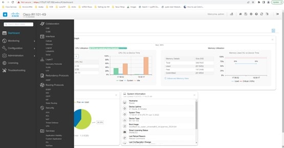
WebUI の使用方法の詳細については、『IR1101 Software Configuration Guide』の「Web User Interface (WebUI)」を参照してください。

ステップ 2

[LoRaWAN] インターフェイスをダブルクリックします。
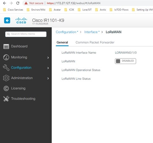
ステップ 3

Cisco lorawan インターフェイスを有効にします。
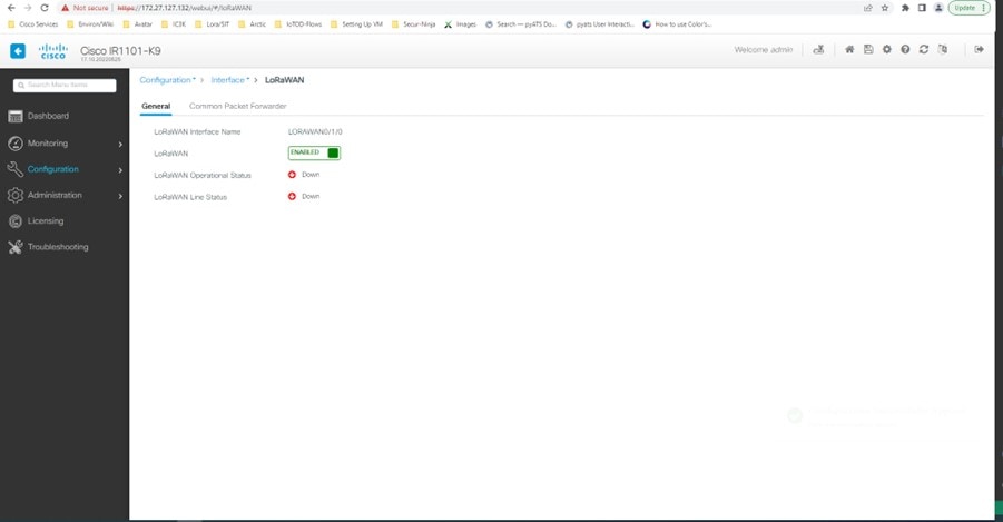
ステップ 4

[Common Packet Forwarder] タブをクリックして、CPF 設定を追加します。
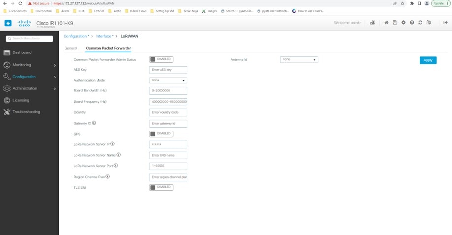
ステップ 5

CPF 設定を追加し、[Common Packet Forwarder Admin Status] を [ENABLED] に設定します。
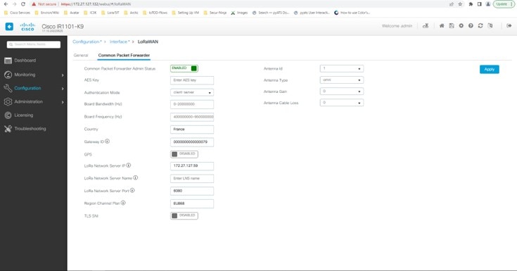

次のタスク

Local Manager を使用したアプリケーション展開プロセスについては、「Cisco IOx Local Manager Workflows」を参照してください。

LoRa テクノロジー向けの共通パケット フォワーダ アプリケーション ホスティング

アプリケーション ホスティングを設定するには、IOx を有効にして、VirtualPortGroup をレイヤ 3 データポートに設定します。これらの手順について、以降のセクションで説明します。

IOx の有効化

Cisco IOx Local Manager へのアクセスを有効にするには、次の作業を実行します。IOx Local Manager を使用することで、ホストシステム上のアプリケーションの管理、制御、モニター、トラブルシューティング、および関連するさまざまなアクティビティを実行できます。

手順

  コマンドまたはアクション 目的

ステップ 1

enable

例:

Router>enable

特権 EXEC モードをイネーブルにします

ステップ 2

configure terminal

例:

Router#configure terminal 

グローバル コンフィギュレーション モードを開始します。

ステップ 3

iox

例:

Router(config)#iox 

Cisco IOx の有効化

ステップ 4

ip http server

例:

Router(config)#ip http server

IPv4 または IPv6 システム上の HTTP サーバーを有効化します。

ステップ 5

ip http secure-server

例:

Router(config)#ip http secure-server

セキュア HTTP(HTTPS)サーバーを有効化します。

ステップ 6

username name privilege level password {0 | 7 | user-password } encrypted-password

例:

Router(config)#username cisco privilege 15 password 0 cisco

ユーザー名ベースの認証システムと権限レベルを確立します。ユーザー名の特権レベルは 15 に設定する必要があります。

ステップ 7

end

例:

Router(config-if)#end 

インターフェイス コンフィギュレーション モードを終了し、特権 EXEC モードに戻ります。

レイヤ 3 データポートへの VirtualPortGroup の設定

複数のレイヤ 3 データポートを 1 つ以上の VirtualPortGroup またはコンテナにルーティングできます。VirtualPortGroup インターフェイスは、アプリケーション ホスティング ネットワークを IOS ルーティングドメインに接続する仮想インターフェイスです。VirutalPortGroups とレイヤ 3 のデータポートは、異なるサブネット上にある必要があります。

手順

  コマンドまたはアクション 目的

ステップ 1

enable

例:

Router> enable

特権 EXEC モードを有効にします。

ステップ 2

configure terminal

例:

Router# configure terminal 

グローバル コンフィギュレーション モードを開始します。

ステップ 3

ip routing

例:

Router(config)#ip routing 

IP ルーティングをイネーブルにしますレイヤ 3 データポートで外部ルーティングを許可するには、ip routing コマンドを有効にする必要があります。

ステップ 4

interface type number

例:

Router(config)#interface gigabitethernet 0/0/0

インターフェイスを設定し、インターフェイスの設定モードを開始します。

ステップ 5

no switchport

例:

Router(config-if)#no switchport

インターフェイスをレイヤ 3 モードにし、スイッチポートではなくルータインターフェイスのように動作させます。

ステップ 6

ip address ip-address mask

例:

Router(config)#ip address 10.1.1.1 255.255.255.0

インターフェイスの IP アドレスを設定します。

ステップ 7

exit

例:

Router(config-if)#exit 

インターフェイス コンフィギュレーション モードを終了し、グローバル コンフィギュレーション モードに戻ります。

ステップ 8

interface type number

例:

Router(config)#interface virtualportgroup 0

インターフェイスを設定し、インターフェイスの設定モードを開始します。

ステップ 9

ip address ip-address mask

例:

Router(config-if)#ip address 192.168.0.1 255.255.255.0 

インターフェイスの IP アドレスを設定します。

ステップ 10

end

例:

Router(config-if)#end 

インターフェイス コンフィギュレーション モードを終了し、グローバル コンフィギュレーション モードに戻ります。

アプリケーション ネットワーキングの設定

アプリケーション vNIC インターフェイスは、コンテナ内の標準イーサネット インターフェイスであり、アプリケーションがパケットを送受信するためにプラットフォーム データ プレーンに接続します。

手順

  コマンドまたはアクション 目的

ステップ 1

enable

例:

Router> enable

特権 EXEC モードをイネーブルにします

ステップ 2

configure terminal

例:

Router#configure terminal 

グローバル コンフィギュレーション モードを開始し、コンフィギュレーション コマンドを 1 行に 1 つずつ入力します。コンフィギュレーション コマンドの入力が終了したら、Ctrl+Z を押します。

ステップ 3

app-hosting appid app1

例:

Router(config)#app-hosting appid app1

アプリケーションを設定し、アプリケーション コンフィギュレーション モードを開始します。

ステップ 4

app-vnic options

例:

Router(config-app-hosting)#app-vnic gateway0 virtualportgroup 0 guest-interface 0

アプリケーション インターフェイスとアプリケーションのゲートウェイを設定します。

ステップ 5

guest-ipaddress ip-address mask

例:

Router(config-app-hosting-gateway0)#guest-ipaddress 192.168.0.2 netmask 255.255.255.0

アプリケーション イーサネット インターフェイス IP アドレスを設定します。

ステップ 6

app-default-gateway options

例:

Router(config-app-hosting-gateway0)#app-default-gateway 192.168.0.1 guest-interface 0

アプリケーションのデフォルトゲートウェイを設定します。

ステップ 7

end

例:

Router#end

グローバル コンフィギュレーション モードを終了し、特権 EXEC モードに戻ります。

アプリケーション ライフサイクル管理

このセクションでは、アプリのインストールとアンインストールのプロセスについて説明します。

手順

  コマンドまたはアクション 目的

ステップ 1

enable

例:

Router> enable

特権 EXEC モードをイネーブルにします

ステップ 2

configure terminal

例:

Router# configure terminal 

グローバル コンフィギュレーション モードを開始し、コンフィギュレーション コマンドを 1 行に 1 つずつ入力します。コンフィギュレーション コマンドの入力が終了したら、Ctrl+Z を押します。

ステップ 3

app-hosting install appid application-name package package-path

例:

Router(config)#app-hosting install appid CPFAPP package flash:cpfv5.tar

指定された場所からアプリケーションをインストールします。アプリケーションは、flash、bootflash、usbflash0 などの任意のローカルストレージの場所からインストールできます。

ステップ 4

app-hosting activate appid application-name

例:

Router#app-hosting activate appid CPFAPP

アプリケーションをアクティブ化します。このコマンドは、すべてのアプリケーションリソース要求を検証し、すべてのリソースが使用可能な場合はアプリケーションがアクティブになります。すべてのリソースが使用可能ではない場合、アクティブ化は失敗します。

ステップ 5

app-hosting start appid application-name

例:

Router#app-hosting start appid CPFAPP

アプリケーションを起動します。このコマンドは、アプリケーションの起動スクリプトをアクティブにします。

ステップ 6

app-hosting stop appid application-name

例:

Router#app-hosting stop appid CPFAPP

アプリケーションを停止します。

ステップ 7

app-hosting deactivate appid application-name

例:

Router#app-hosting deactivate appid CPFAPP

アプリケーションに割り当てられているすべてのリソースを非アクティブにします。

ステップ 8

app-hosting uninstall appid application-name

例:

Router(config)#app-hosting uninstall appid CPFAPP

保存されているすべてのパッケージとイメージをアンインストールし、アプリケーションに対するすべての変更と更新を削除します。

アプリケーション ホスティング コンフィギュレーションの確認

このセクションでは、アプリケーション ホスティング コンフィギュレーションを確認するためのコマンドを示します。

すべての IOx サービスのステータスを表示する

Router#show iox-service

IOx Infrastructure Summary:
---------------------------
IOx service (CAF)              : Running
IOx service (HA)               : Not Supported
IOx service (IOxman)           : Running
IOx service (Sec storage)      : Running
Libvirtd 5.5.0                 : Running
Dockerd v19.03.13-ce           : Running

Router#

アプリケーションに関する詳細情報を表示する

Router#show app-hosting detail
pp id                         : cp
Owner                         : iox
State                         : RUNNING

Application	
  Type                        : docker
  Name                        : cpf
  Version                     : vl
  Description                 : buildkit.dockerfile.vO
  Author                      :
  Path                        : bootflash:cpfv5.tar
  URL Path                    :
  Multicast                   : yes
 Activated profile name       :custom

Resource reservation
  Memory                      :128 MB
  Disk                        :10 MB
  CPU                         :400 units
  CPU-percent                 :35 %
  VCPU                        :1

Platform resource profiles
  Profile Name	        	CPU(unit)  Memory(MB)  Disk(MB)
  -------------------------------------------------------------

Attached devices
  Type	           Name	               Alias
  ------------------------------------------
  serial/shell     iox_console_shell   serialO 
  serial/aux       iox_console_aux     serial1 
  serial/syslog    iox_syslog          serial2 
  serial/trace     iox_trace           serial3

Network interfaces
----------------------------------------------
ethO:
  MAC address               : 52:54:dd:f2:f4:87
  IPv4 address              : 192.168.0.9
  IPv6 address              ::
  Network name              : VPGO


Docker
------
Run-time information 
  Command                   :
  Entry-point               : /station/cpf
  Run options in use        : --device /dev/lorawan_ttyl:/dev/ttyACMO -v /bootflash/lorawan_0:/cpf/ 
  Package run options       : 

Application health information 
  Status                    : 0
  Last probe error          : 
  Last probe output         :

アプリケーションとそれらのステータスの一覧を表示する

Router#show app-hosting list
App id State
---------------------------------------------
CPFAPP RUNNING

コンソールコマンドを使用してアプリケーションに接続する

Ctrl+C を 3 回押して、コンソールの接続を解除します。

Router# app-hosting app-hosting connect appid CPFAPP console 
Connected to appliance. Exit using ^c^c^c
root@ir510-lxc:~#
root@ir510-lxc:~#
root@ir510-lxc:~#
root@ir510-lxc:~#
root@ir510-lxc:~#
root@ir510-lxc:~# IR11014006#

LoRa テクノロジー向けの Actility パケット フォワーダ アプリケーション ホスティング

以下は、アプリケーション ホスティングを設定するための前提条件です。コンテナとホスト間で ssh キーを共有するための新しいプロセスがあります。

ホストで以下を実行します。

ユーザー名とパスワードを追加します。

config terminal 
username actility privilege 15 password 0 Actility_Password 
exit 

次のオプションを使用して Docker コンテナを実行します。

  • device /dev/ttyACM0:/dev/ttyACM0

  • env HOST_IP_ADDR=192.168.42.11

  • env HOST_USER=actility

  • env HOST_SETUP_PASSWORD=actilityPassword

上記の Docker コンテナオプションでは、デフォルトの IP アドレス、ユーザー名、およびパスワードに注意してください。これらは設定に合わせて変更します。


(注)  


最初のインストール後は、actility ユーザー(username actility privilege 15)にパスワードがありません。ThingPark Long Range Relay(LRR)ソフトウェアを再インストールする場合は、username actility privilege 15 password 0 actilityPassword を再度設定する必要があります。

アプリケーション ホスティングを設定するには、IOx を有効にして、VirtualPortGroup をレイヤ 3 データポートに設定します。これらの手順について、以降のセクションで説明します。

IOx の有効化

Cisco IOx Local Manager へのアクセスを有効にするには、次の作業を実行します。IOx Local Manager を使用することで、ホストシステム上のアプリケーションの管理、制御、モニター、トラブルシューティング、および関連するさまざまなアクティビティを実行できます。

手順

  コマンドまたはアクション 目的

ステップ 1

enable

例:

Router>enable

特権 EXEC モードを有効にします。

ステップ 2

configure terminal

例:

Router#configure terminal 

グローバル コンフィギュレーション モードを開始します。

ステップ 3

iox

例:

Router(config)#iox 

Cisco IOx を有効にします。

ステップ 4

ip http server

例:

Router(config)#ip http server

IPv4 または IPv6 システム上の HTTP サーバーを有効化します。

ステップ 5

ip http secure-server

例:

Router(config)#ip http secure-server

セキュア HTTP(HTTPS)サーバーを有効化します。

ステップ 6

username name privilege level password {0 | 7 | user-password } encrypted-password

例:

Router(config)#username cisco privilege 15 password 0 cisco

ユーザー名ベースの認証システムと権限レベルを確立します。ユーザー名の特権レベルは 15 に設定する必要があります。

ステップ 7

end

例:

Router(config-if)#end 

インターフェイス コンフィギュレーション モードを終了し、特権 EXEC モードに戻ります。

レイヤ 3 データポートへの VirtualPortGroup の設定

複数のレイヤ 3 データポートを 1 つ以上の VirtualPortGroup またはコンテナにルーティングできます。VirtualPortGroup インターフェイスは、アプリケーション ホスティング ネットワークを IOS ルーティングドメインに接続する仮想インターフェイスです。VirutalPortGroups とレイヤ 3 のデータポートは、異なるサブネット上にある必要があります。

手順

  コマンドまたはアクション 目的

ステップ 1

enable

例:

Router> enable

特権 EXEC モードを有効にします。

ステップ 2

configure terminal

例:

Router# configure terminal 

グローバル コンフィギュレーション モードを開始します。

ステップ 3

ip routing

例:

Router(config)#ip routing 

IP ルーティングをイネーブルにしますレイヤ 3 データポートで外部ルーティングを許可するには、ip routing コマンドを有効にする必要があります。

ステップ 4

interface type number

例:

Router(config)#interface gigabitethernet 0/0/0

インターフェイスを設定し、インターフェイスの設定モードを開始します。

ステップ 5

no switchport

例:

Router(config-if)#no switchport

インターフェイスをレイヤ 3 モードにし、スイッチポートではなくルータインターフェイスのように動作させます。

ステップ 6

ip address dhcp

例:

Router(config)#ip address dhcp

インターフェイスの IP アドレスを設定します。

ステップ 7

exit

例:

Router(config-if)#exit 

インターフェイス コンフィギュレーション モードを終了し、グローバル コンフィギュレーション モードに戻ります。

ステップ 8

interface type number

例:

Router(config)#interface virtualportgroup 0

インターフェイスを設定し、インターフェイスの設定モードを開始します。

ステップ 9

ip address ip-address mask

例:

Router(config-if)#ip address 192.168.2.1 255.255.255.0 

インターフェイス コンフィギュレーション モードを終了し、グローバル コンフィギュレーション モードに戻ります。

ステップ 10

end

例:

Router(config-if)#end 

インターフェイス コンフィギュレーション モードを終了し、グローバル コンフィギュレーション モードに戻ります。

アプリケーション ネットワーキングの設定

アプリケーション vNIC インターフェイスは、コンテナ内の標準イーサネット インターフェイスであり、アプリケーションがパケットを送受信するためにプラットフォーム データ プレーンに接続します。

手順

  コマンドまたはアクション 目的

ステップ 1

enable

例:

Router> enable

特権 EXEC モードを有効にします。

ステップ 2

configure terminal

例:

Router#configure terminal 

グローバル コンフィギュレーション モードを開始し、コンフィギュレーション コマンドを 1 行に 1 つずつ入力します。コンフィギュレーション コマンドの入力が終了したら、Ctrl+Z を押します。

ステップ 3

app-hosting appid app1

例:

Router(config)#app-hosting appid app1

アプリケーションを設定し、アプリケーション コンフィギュレーション モードを開始します。

ステップ 4

app-vnic options

例:

Router(config-app-hosting)#app-vnic gateway0 virtualportgroup 0 guest-interface 0

アプリケーション インターフェイスとアプリケーションのゲートウェイを設定します。

ステップ 5

guest-ipaddress ip-address mask

例:

Router(config-app-hosting-gateway0)#guest-ipaddress 192.168.2.9 netmask 255.255.255.0

アプリケーション イーサネット インターフェイス IP アドレスを設定します。

ステップ 6

app-default-gateway options

例:

Router(config-app-hosting-gateway0)#app-default-gateway 192.168.2.1 guest-interface 0

アプリケーションのデフォルトゲートウェイを設定します。

ステップ 7

end

例:

Router#end

グローバル コンフィギュレーション モードを終了し、特権 EXEC モードに戻ります。

アプリケーション ライフサイクル管理

このセクションでは、アプリのインストールとアンインストールのプロセスについて説明します。

手順

  コマンドまたはアクション 目的

ステップ 1

enable

例:

Router> enable

特権 EXEC モードを有効にします。

ステップ 2

configure terminal

例:

Router# configure terminal 

グローバル コンフィギュレーション モードを開始し、コンフィギュレーション コマンドを 1 行に 1 つずつ入力します。コンフィギュレーション コマンドの入力が終了したら、Ctrl+Z を押します。

ステップ 3

app-hosting install appid application-name package package-path

例:

Router(config)#app-hosting install appid APFAPP package flash:actility_tar_gz.tar

指定された場所からアプリケーションをインストールします。アプリケーションは、flash、bootflash、usbflash0 などの任意のローカルストレージの場所からインストールできます。

ステップ 4

app-hosting activate appid application-name

例:

Router#app-hosting activate appid APFAPP

アプリケーションをアクティブ化します。このコマンドは、すべてのアプリケーションリソース要求を検証し、すべてのリソースが使用可能な場合はアプリケーションがアクティブになります。すべてのリソースが使用可能ではない場合、アクティブ化は失敗します。

ステップ 5

app-hosting start appid application-name

例:

Router#app-hosting start appid APFAPP

アプリケーションを起動します。このコマンドは、アプリケーションの起動スクリプトをアクティブにします。

ステップ 6

app-hosting stop appid application-name

例:

Router#app-hosting stop appid APFAPP

アプリケーションを停止します。

ステップ 7

app-hosting deactivate appid application-name

例:

Router#app-hosting deactivate appid APFAPP

アプリケーションに割り当てられているすべてのリソースを非アクティブにします。

ステップ 8

app-hosting uninstall appid application-name

例:

Router(config)#app-hosting uninstall appid APFAPP

保存されているすべてのパッケージとイメージをアンインストールし、アプリケーションに対するすべての変更と更新を削除します。

アプリケーション ホスティング コンフィギュレーションの確認

このセクションでは、アプリケーション ホスティング コンフィギュレーションを確認するためのコマンドを示します。

すべての IOx サービスのステータスを表示する

Router#show iox-service

IOx Infrastructure Summary:
---------------------------
IOx service (CAF)              : Running
IOx service (HA)               : Not Supported
IOx service (IOxman)           : Running
IOx service (Sec storage)      : Running
Libvirtd 5.5.0                 : Running
Dockerd v19.03.13-ce           : Running

Router#

アプリケーションに関する詳細情報を表示する

Router#show app-hosting detail
 App id                 : APFC1
Owner                  : iox
State                  : RUNNING
Application
  Type                 : docker
  Name                 : base-rootfs-runtime-actility
  Version              : latest
  Description          : Actility LRR
  Author               : Actility
  Path                 : bootflash:actility_lrr_76.tar.gz
  URL Path             :
  Multicast            : yes
Activated profile name : custom

Resource reservation
  Memory               : 64 MB
  Disk                 : 2 MB
  CPU                  : 50 units
  CPU-percent          : 5 %
  VCPU                 : 1

Platform resource profiles
  Profile Name                  CPU(unit)  Memory(MB)  Disk(MB)
  --------------------------------------------------------------

Attached devices
  Type              Name               Alias
  ---------------------------------------------
  serial/shell     iox_console_shell   serial0
  serial/aux       iox_console_aux     serial1
  serial/syslog    iox_syslog          serial2
  serial/trace     iox_trace           serial3

Network interfaces
   ---------------------------------------
eth0:
   MAC address         : 52:54:dd:16:24:0a
   IPv4 address        : 192.168.2.9
   IPv6 address        : ::
   Network name        : VPG0


Docker
------
Run-time information
  Command              :
  Entry-point          :  /etc/init.d/lrr_iox_top start
  Run options in use   : --device /dev/ttyACM0:/dev/ttyACM0 --env HOST_IP_ADDR=192.168.2.1 --env HOST_USER=actility --env HOST_SETUP_PASSWORD=actilityPassword
  Package run options  :
Application health information
  Status               : 0
  Last probe error     :
  Last probe output    :

Router#

アプリケーションとそれらのステータスの一覧を表示する

Router#show app-hosting list
App id State
---------------------------------------------
APFAPP RUNNING

次のコマンドを使用してアプリケーションに接続する

Ctrl+C を 3 回押して、コンソールの接続を解除します。

Router# app-hosting app-hosting connect appid APFAPP session 
/home/actility/var/log/lrr

/var/volatile/log/_LRRLOG # pwd
/home/actility/var/log/lrr

/var/volatile/log/_LRRLOG # ls -lrt
-rw-r--r--    1 root     root            19 Jul  7 0646 SHELL.log
-rw-r--r--    1 root     support         53 Jul  7 0647 suplog.log
-rw-r--r--    1 root     support         99 Jul  7 0648 pkiconfig.txt
-rw-r--r--    1 root     root           430 Jul  7 0720 lrr_startup_service.log
-rw-r--r--    2 root     root          1620 Jul  7 0721 gwmgr_04.log
-rw-r--r--    2 root     root          1620 Jul  7 0721 gwmgr.log
-rw-r--r--    1 root     root          1657 Jul  7 0721 radioparams.txt
-rw-r--r--    1 root     root          2227 Jul  7 0721 logicchan.txt
-rw-r--r--    1 root     root          1118 Jul  7 1721 stat.html
-rw-r--r--    2 root     root         50515 Jul  7 1721 TRACE_04.log
-rw-r--r--    2 root     root         50515 Jul  7 1721 TRACE.log
-rw-r--r--    1 root     root            64 Jul  7 1723 lrcstatuslink.txt
/var/volatile/log/_LRRLOG #

実行中のコンフィギュレーションのアプリケーション ホスティングを表示する

Router#show running-config | sec app-hosting
 action 2 cli command "app-hosting stop appid APFC1"
 action 4 cli command "app-hosting start appid APFC1"
app-hosting appid APFC1
 app-vnic gateway0 virtualportgroup 0 guest-interface 0
  guest-ipaddress 192.168.2.9 netmask 255.255.255.0
 app-default-gateway 192.168.2.1 guest-interface 0
 app-resource docker
  run-opts 1 "--device /dev/ttyACM0:/dev/ttyACM0"
  run-opts 2 "--env HOST_IP_ADDR=192.168.2.1"
  run-opts 3 "--env HOST_USER=actility"
  run-opts 4 "--env HOST_SETUP_PASSWORD=actilityPassword"
Router#

サンプル実行コンフィギュレーション

次に、IR1101 からの場合の例を示します。

Router#show running-config brief
Building configuration...

Current configuration  7651 bytes
!
! Last configuration change at 072004 UTC Thu Jul 7 2022 by actility
! NVRAM config last updated at 065725 UTC Thu Jul 7 2022 by actility
!
version 17.9
service timestamps debug datetime msec
service timestamps log datetime msec
service call-home
platform qfp utilization monitor load 80
platform hardware throughput level 250M
platform punt-keepalive disable-kernel-core
!
hostname Router
!
boot-start-marker
boot system flashir1101-universalk9.S2C.SSA.bin
boot-end-marker
!
!
aaa new-model
!
!
aaa authentication login default local
aaa authorization exec default local
aaa authorization network FlexVPN_Author local
!
!
aaa session-id common
!
!
login block-for 60 attempts 3 within 30
login delay 3
login on-success log
ipv6 unicast-routing
!
!
subscriber templating
!
!
multilink bundle-name authenticated
!
!
crypto pki trustpoint TP-self-signed-1150468717
 enrollment selfsigned
 subject-name cn=IOS-Self-Signed-Certificate-1150468717
 revocation-check none
 rsakeypair TP-self-signed-1150468717
!
crypto pki trustpoint SLA-TrustPoint
 enrollment pkcs12
 revocation-check crl
!
crypto pki trustpoint ActilityTP-slrc
 enrollment terminal
 revocation-check none
!
crypto pki trustpoint ActilityTP
 enrollment pkcs12
 revocation-check crl
 rsakeypair ActilityTP
!
crypto pki trustpoint ActilityTP-rrr1
 revocation-check crl
!
!
crypto pki certificate map FlexVPN_Cert_Map 1
 subject-name co slrc1_prod-us_actility-tpe-ope
!
crypto pki certificate map FlexVPN_Cert_Map 2
 subject-name co slrc2_prod-us_actility-tpe-ope
!
crypto pki certificate chain TP-self-signed-1150468717
 certificate self-signed 01
crypto pki certificate chain SLA-TrustPoint
 certificate ca 01
crypto pki certificate chain ActilityTP-slrc
 certificate ca 61A845069BBFF60B
crypto pki certificate chain ActilityTP
 certificate 06BF5FDCF5EBD17C
 certificate ca 3A96CABF858AAD9A
crypto pki certificate chain ActilityTP-rrr1
 certificate ca 00F35AC229699BABA8
!
!
no license feature hseck9
license udi pid IR1101-K9 sn FCW24160HQ7
license boot level network-advantage
memory free low-watermark processor 45069
!
diagnostic bootup level minimal
!
spanning-tree extend system-id
!
!
username admin privilege 15 password 0 cisco
username iox privilege 15 password 0 iox
username dockeruser
username actility privilege 15
!
redundancy
!
crypto ikev2 authorization policy FlexVPN_Author_Policy
!
!
crypto ikev2 profile FlexVPN_IKEv2_Profile
 match certificate FlexVPN_Cert_Map
 identity local dn
 authentication remote rsa-sig
 authentication local rsa-sig
 pki trustpoint ActilityTP sign
 pki trustpoint ActilityTP-rrr1 verify
 pki trustpoint ActilityTP-slrc verify
 dpd 30 3 periodic
 aaa authorization group cert list FlexVPN_Author FlexVPN_Author_Policy
!
crypto ikev2 dpd 30 3 periodic
crypto ikev2 fragmentation mtu 1260
!
controller Cellular 0/3/0
!
!
vlan internal allocation policy ascending
!
!
crypto ipsec transform-set FlexVPN_IPsec_Transform_Set esp-aes 256 esp-sha256-hmac
 mode tunnel
!
crypto ipsec profile FlexVPN_IPsec_Profile
 set transform-set FlexVPN_IPsec_Transform_Set
 set ikev2-profile FlexVPN_IKEv2_Profile
!
!
interface Tunnel201
 ip address negotiated
 ip nat outside
 ipv6 enable
 tunnel source GigabitEthernet0/0/0
 tunnel mode ipsec dual-overlay
 tunnel destination 52.200.161.236
 tunnel path-mtu-discovery
 tunnel protection ipsec profile FlexVPN_IPsec_Profile
!
interface Tunnel202
 ip address negotiated
 ip nat outside
 ipv6 enable
 tunnel source GigabitEthernet0/0/0
 tunnel mode ipsec dual-overlay
 tunnel destination 54.226.90.83
 tunnel path-mtu-discovery
 tunnel protection ipsec profile FlexVPN_IPsec_Profile
!
interface VirtualPortGroup0
 ip address 192.168.2.1 255.255.255.0
 ip nat inside
 no mop enabled
 no mop sysid
!
interface GigabitEthernet0/0/0
 ip dhcp client client-id ascii cisco-ac4a.67f9.ae00-Gi0/0/0
 ip address dhcp
 ip nat outside
 ipv6 dhcp client request vendor
 ipv6 address dhcp
 ipv6 address autoconfig
 ipv6 enable
!
interface FastEthernet0/0/1
!
interface FastEthernet0/0/2
!
interface FastEthernet0/0/3
!
interface FastEthernet0/0/4
!
interface GigabitEthernet0/0/5
!
interface Cellular0/3/0
 description backup_WAN
 ip address negotiated
 ip nat outside
 ip tcp adjust-mss 1460
 load-interval 30
 shutdown
 dialer in-band
 dialer idle-timeout 0
 dialer-group 1
 ipv6 enable
 pulse-time 1
!
interface Cellular0/3/1
 no ip address
!
interface Vlan1
 no ip address
!
interface Async0/2/0
 no ip address
 encapsulation scada
!
interface LORAWAN0/1/0
 no ip address
 shutdown
 arp timeout 0
 no mop enabled
 no mop sysid
!
iox
ip forward-protocol nd
ip tcp selective-ack
ip tcp mss 1460
ip tcp window-size 131072
ip http server
ip http auth-retry 3 time-window 1
ip http authentication local
ip http secure-server
ip http client source-interface GigabitEthernet0/0/0
ip tftp source-interface GigabitEthernet0/0/0
ip nat inside source list Tunnel201 interface Tunnel201 overload
ip nat inside source list Tunnel202 interface Tunnel202 overload
ip nat inside source list internetacces_Fromdocker interface GigabitEthernet0/0/0 overload
ip nat inside source list internetacces_Fromdocker_cell interface Cellular0/3/0 overload
ip route 10.102.12.0 255.255.255.0 Tunnel201
ip route 10.102.22.0 255.255.255.0 Tunnel202
ip ssh bulk-mode 131072
ip ssh version 2
ip ssh pubkey-chain
  username actility
   key-hash ecdsa-sha2-nistp256 FA249B09C77A121A9759A0FC724F58A8 root@a89e080e0c1e
ip ssh server algorithm publickey ecdsa-sha2-nistp256
ip scp server enable
!
!
ip access-list extended Tunnel201
 10 permit ip host 192.168.2.9 host 10.102.12.10
ip access-list extended Tunnel202
 10 permit ip host 192.168.2.9 host 10.102.22.10
ip access-list extended internetacces_Fromdocker
 10 permit ip 192.168.2.0 0.0.0.255 host 8.8.8.8
 11 permit ip 192.168.2.0 0.0.0.255 host 52.200.161.236
ip access-list extended internetacces_Fromdocker_cell
 10 permit ip host 192.168.2.9 host 8.8.8.8
!
ip sla 1
 icmp-echo 8.8.8.8 source-interface GigabitEthernet0/0/0
ip sla schedule 1 life forever start-time now
ip sla 2
 icmp-echo 8.8.8.8 source-interface Cellular0/3/0
ip sla schedule 2 life forever start-time now
ip access-list standard 1
 11 permit any
dialer-list 1 protocol ip permit
!
!
control-plane
!
!
line con 0
 stopbits 1
line 0/0/0
line 0/2/0
line vty 0 4
 transport input ssh
line vty 5 14
 transport input ssh
!
call-home
 ! If contact email address in call-home is configured as sch-smart-licensing@cisco.com
 ! the email address configured in Cisco Smart License Portal will be used as contact email address to send SCH notifications.
 contact-email-addr sch-smart-licensing@cisco.com
 profile "CiscoTAC-1"
  active
  destination transport-method http
ntp server 0.pool.ntp.org
ntp server 1.pool.ntp.org
ntp server 2.pool.ntp.org
!
!
event manager applet restart_actility_lrr
 event none sync yes maxrun 60
 action 1 cli command "enable"
 action 2 cli command "app-hosting stop appid APFC1"
 action 3 wait 5
 action 4 cli command "app-hosting start appid APFC1"
event manager applet Cellular_Activate
 event track 1 state down
 action 1 cli command "enable"
 action 2 cli command "configure terminal"
 action 3 cli command "interface Cellular 0/3/0"
 action 4 cli command "no shut"
 action 5 cli command "end"
event manager applet Cellular_Deactivate
 event track 1 state up
 action 1 cli command "enable"
 action 2 cli command "config terminal"
 action 3 cli command "interface Cellular 0/3/0"
 action 4 cli command "shutdown"
 action 5 cli command "end"
!
end

Router#

debug コマンド

次のデバッグコマンドを使用できます。

Router#debug lorawan ?
cli     lorawan cli trace
errors  lorawan error messages
info    lorawan info messages
Router#
Router#debug lorawan cli
cli trace debugging is on
Router#

Router#debug lorawan errors
error debugging is on
Router#

Router#debug lorawan info
info debugging is on
Router#