FCoE の設定

この章は、次の内容で構成されています。

FCoE のトポロジ

直接接続された CNA のトポロジ

Cisco Nexus デバイスは、次の図のようにファイバ チャネル フォワーダ(FCF)として配置できます。
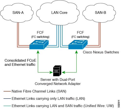
図 1. 直接接続された FCF
直接接続された FCF

FCF が FCoE ノード(ENode)と他の FCF との間の中継に使用されないようにするため、FIP フレームは次のルールに従って処理されます。この処理により、異なるファブリック内の ENode と FCF との間のログイン セッションも回避されます。

  • CNA から受信された FIP の送信要求フレームおよびログイン フレームは FCF により処理され、転送されません。

  • FCF が他の FCF からインターフェイスを介して送信要求およびアドバタイズメントを受信すると、次のような処理が実行されます。

    • フレーム内の FC-MAP 値が FCF の FC-MAP 値と一致する(FCF が同一のファブリック内にある)場合、これらのフレームは無視され、廃棄されます。

    • FIP フレーム内の FC-MAP 値が FCF の FC-MAP 値と一致しない(FCF が異なるファブリック内にある)場合、インターフェイスが「FCoE 孤立」状態になります。

中継用の Cisco Nexus FCF を経由した場合に限って到達可能な FCF については、CNA から検出することもログインすることもできません。ハードウェアの制約上、Cisco Nexus デバイスでは、CNA と他の FCF との間の FCoE 中継機能は実行できません。

Cisco Nexus FCF では FCoE 中継機能が実行できないため、FCoE VLAN のアクティブな Spanning Tree Protocol(STP)パスが必ず CNA と FCF の間の直接接続されたリンクを経由するようにネットワーク トポロジを設計する必要があります。FCoE VLAN は、直接接続されたリンクに対してだけ設定するようにしてください。

リモート接続された CNA のトポロジ

Cisco Nexus デバイスは、次の図のようにリモート接続された CNA に対する FCF としては配置できますが、FIP スヌーピング ブリッジとしては配置できません。
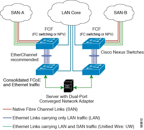
図 2. リモート接続された FCF
リモート接続されたファイバチャネル フォワーダ

FCF が ENode と他の FCF との間の中継に使用されないようにするため、FIP フレームは次のルールに従って処理されます。この処理により、異なるファブリック内の ENode と FCF との間のログイン セッションも回避されます。

  • CNA から受信された FIP の送信要求フレームおよびログイン フレームは FCF により処理され、転送されません。

  • FCF が他の FCF からインターフェイスを介して送信要求およびアドバタイズメントを受信すると、次のような処理が実行されます。

    • フレーム内の FC-MAP 値が FCF の FC-MAP 値と一致する(FCF が同一のファブリック内にある)場合、これらのフレームは無視され、廃棄されます。

    • FIP フレーム内の FC-MAP 値が FCF の FC-MAP 値と一致しない(FCF が異なるファブリック内にある)場合、インターフェイスが「FCoE 孤立」状態になります。

Cisco Nexus FCF では FCoE 中継機能が実行できないため、FCoE VLAN のアクティブな STP パスが必ず CNA と FCF の間の直接接続されたリンクを経由するようにネットワーク トポロジを設計する必要があります。FCoE VLAN は、直接接続されたリンクに対してだけ設定するようにしてください。
FCoE のベスト プラクティス

直接接続された CNA のベスト プラクティス

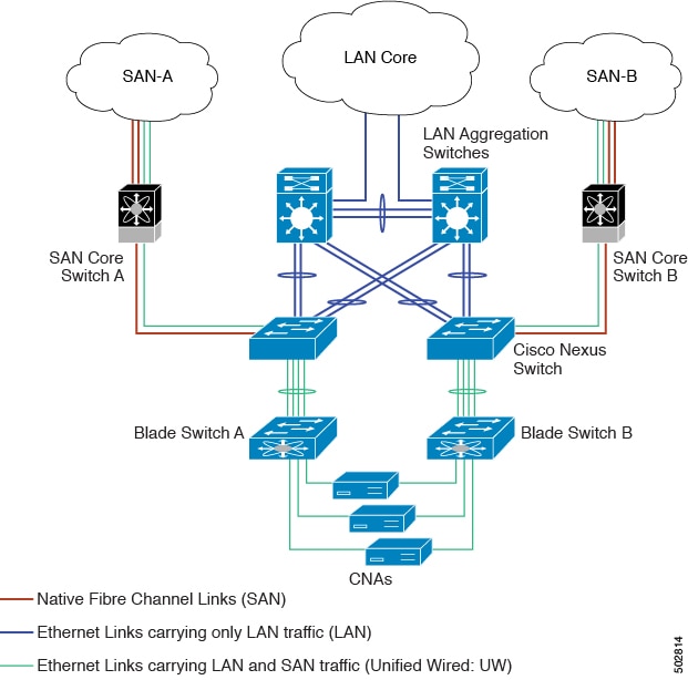
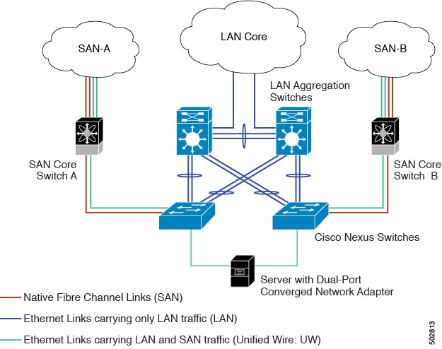
次の図は、直接接続された CNA と Cisco Nexus デバイスを使用したアクセス ネットワークのベスト プラクティス トポロジを示したものです。

図 3. 直接接続された CNA
直接接続された CNA

上図の配置トポロジに対する設定のベスト プラクティスは次のとおりです。

  1. SAN 内の仮想ファブリック(VSAN)ごとにトラフィックを伝送できるよう、それぞれの統合アクセス スイッチに一意の専用 VLAN を設定する必要があります(VSAN 1 用に VLAN 1002、VSAN 2 用に VLAN 1003 など)。マルチ スパニングツリー(MST)を有効にした場合は、FCoE VLAN に対して別個の MST インスタンスを使用する必要があります。

  2. ユニファイド ファブリック(UF)リンクをトランク ポートとして設定する必要があります。ネイティブ VLAN として FCoE VLAN を設定しないでください。仮想ファイバ チャネル インターフェイスの VF_Port トランキングおよび VSAN 管理を拡張できるよう、すべての FCoE VLAN を UF リンクのメンバとして設定する必要があります。


    (注)  

    イーサネット トラフィックおよび FCoE トラフィックはどちらも、統合ワイヤにより伝送されます。


  3. UF リンクをスパニングツリー エッジ ポートとして設定する必要があります。

  4. FCoE トラフィックの伝送用として指定されていないイーサネット リンクのメンバとして FCoE VLAN を設定しないでください。これは、FCoE VLAN に使用する STP のスコープを UF リンクに限定する必要があるためです。

  5. LAN の代替パス用に(同一または別の SAN ファブリックにある)統合アクセス スイッチをイーサネット リンク経由で相互に接続する必要がある場合は、すべての FCoE VLAN をメンバーシップから除外することを、これらのリンクに対して明示的に設定する必要があります。この設定により、FCoE VLAN に使用する STP のスコープが UF リンクに限定されます。

  6. SAN-A および SAN-B の FCoE に対してはそれぞれ別々の FCoE VLAN を使用する必要があります。

リモート接続された CNA のベスト プラクティス

次の図は、リモート接続された CNA と Cisco Nexus デバイスを使用したアクセス ネットワークのベスト プラクティス トポロジを示したものです。

図 4. リモート接続された CNA
リモート接続された CNA

上図の配置トポロジに対する設定のベスト プラクティスは次のとおりです。

  1. SAN 内の仮想ファブリック(VSAN)ごとにトラフィックを伝送できるよう、それぞれの統合アクセス スイッチに一意の専用 VLAN を設定する必要があります(VSAN 1 用に VLAN 1002、VSAN 2 用に VLAN 1003 など)。MST を有効にした場合は、FCoE VLAN に対して別個の MST インスタンスを使用する必要があります。

  2. ユニファイド ファブリック(UF)リンクをトランク ポートとして設定する必要があります。ネイティブ VLAN として FCoE VLAN を設定しないでください。仮想ファイバ チャネル インターフェイスの VF_Port トランキングおよび VSAN 管理を拡張できるよう、すべての FCoE VLAN を UF リンクのメンバとして設定する必要があります。


    (注)  

    イーサネット トラフィックおよび FCoE トラフィックはどちらも、ユニファイド ファブリック リンクにより伝送されます。


  3. CNA およびブレード スイッチを、スパニングツリー エッジ ポートとして設定する必要があります。

  4. 新しいリンクやブレード スイッチのプロビジョニングなど、さまざまなイベントに伴って実行される STP の再コンバージェンスの際に障害が発生しないよう、各ブレード スイッチは、(できれば EtherChannel を介して)ただ 1 つの Cisco Nexus 統合アクセス スイッチに接続される必要があります。

  5. Cisco Nexus 統合アクセス スイッチには、それに接続されているブレード スイッチよりも高い STP プライオリティを設定する必要があります。そうすることで、統合アクセス スイッチがスパニングツリーのルートであり、かつそれに接続されているすべてのブレード スイッチがダウンストリーム ノードとなるような FCoE VLAN のアイランドを作成できます。

  6. FCoE トラフィックの伝送用として指定されていないイーサネット リンクのメンバとして FCoE VLAN を設定しないでください。これは、FCoE VLAN に使用する STP のスコープを UF リンクに限定する必要があるためです。

  7. LAN の代替パス用に、統合アクセス スイッチやブレード スイッチをイーサネット リンク経由で相互に接続する必要がある場合は、これらのリンクに対してすべての FCoE VLAN をメンバーシップから除外することを、明示的に設定する必要があります。この設定により、FCoE VLAN に使用する STP のスコープが UF リンクに限定されます。

  8. SAN-A および SAN-B の FCoE に対してはそれぞれ別々の FCoE VLAN を使用する必要があります。

ガイドラインと制約事項

FC/FCoE には、次のガイドラインと制約事項があります。

  • VLAN 1 では FCoE をイネーブルにできません。

  • LLDP はデフォルトでは有効になっていないため、FCoE を有効にするには、feature lldp を使用して LLDP 機能を有効にする必要があります。

  • FCOE は、銅線 SFP ではサポートされていません。

  • FC/FCoE 構成はロールバックをサポートしていません。FC/FCoE 構成が存在する場合は、ベストエフォート オプションを使用します。他のすべての構成は成功しますが、FC/FCoE 構成ではエラー メッセージが表示されます。

  • FCoE は 10 ギガビット、25 ギガビット、40 ギガビットおよび 100 ギガビット イーサネットインターフェイスでサポートされます。100G ブレイクアウト (4x25G) および 40G ブレイクアウト (4x10G) は、FCoE インターフェイスでサポートされています。

  • Cisco Nexus デバイス インターフェイスのポート チャネルでは、複数のインターフェイスが設定されている場合、直接接続 FCoE(つまりバインド インターフェイスを介して CNA に直接接続された FCoE)はサポートされていません。単一リンクのポート チャネル上では、直接接続 FCoE がサポートされています。これにより、1 つの 10/25/40/100 GB リンクを持つ仮想ポート チャネル(vPC)を介して各アップストリーム スイッチに接続された CNA からの FCoE を実現できます。


(注)  

FC/FCoE のデフォルトの Quality of Service(QoS)ポリシーの説明については、ご使用のデバイスの Quality of Service についてのガイドを参照してください。ご使用の Nexus ソフトウェア リリース版を参照してください。このマニュアルの入手可能なバージョンは、次のサイトから取得できます:https://www.cisco.com/c/en/us/support/switches/nexus-9000-series-switches/products-installation-and-configuration-guides-list.html


FC/FCoE の構成

TCAM カービングの実行

ここでは、TCAM カービングの実行方法について説明します。

手順の概要

  1. 機能 FCoE をインストールします。
  2. fcoe が完全に機能するように、次のコマンドを設定します(まだ設定されていない場合)。
  3. TCAM カービングを実行します。
  4. 設定された TCAM リージョン サイズを確認するには、show hardware access-list tcam region コマンドを使用します。
  5. 構成を保存し、コマンド reload を使用して、スイッチをリロードします。

手順の詳細


ステップ 1

機能 FCoE をインストールします。

switch(config)# install feature-set fcoe
    switch(config)# switch(config)# feature-set fcoe
ステップ 2

fcoe が完全に機能するように、次のコマンドを設定します(まだ設定されていない場合)。

hardware access-list tcam region ing-ifacl 256
hardware access-list tcam region ing-redirect 256

256 は、FC/FCoE の ing-ifacl および ing-redirect リージョンに必要な最小 tcam スペースです。

(注)   

現在の tcam の構成を確認するには、show hardware access-list tcam region コマンドを使用します。

必要な tcam スペースが使用できない場合は、hardware access-list tcam region ing-racl 1536 コマンドを使用して ing-racl リージョンを縮小できます。

ステップ 3

TCAM カービングを実行します。

例:


    Switch(config)# hardware access-list tcam region ing-racl 1536
    Switch(config)# hardware access-list tcam region ing-ifacl 256
    Switch(config)# hardware access-list tcam region ing-redirect 256
ステップ 4

設定された TCAM リージョン サイズを確認するには、show hardware access-list tcam region コマンドを使用します。

例:


  Switch(config)# show hardware access-list tcam region
  Switch(config)# 
ステップ 5

構成を保存し、コマンド reload を使用して、スイッチをリロードします。

例:


  Switch(config)# reload
  Switch(config)# 

次のタスク

TCAM のカービング後には、スイッチをリロードする必要があります。

LLDP の設定

ここでは、LLDP の設定方法について説明します。

手順の概要

  1. configure terminal
  2. [no] feature lldp

手順の詳細


ステップ 1

configure terminal

グローバル設定モードを開始します。

ステップ 2

[no] feature lldp

デバイス上で LLDP をイネーブルまたはディセーブルにします。LLDP はデフォルトでディセーブルです。


デフォルトQoSの設定

FCoE のデフォルト ポリシーには、ネットワーク QoS、出力キューイング、入力キューイング、QoS の 4 種類があります。FCoE デフォルト ポリシーを有効にするには、feature-set fcoe command コマンドを使用して FCoE NPV 機能を有効にします。デフォルトの QoS 入力ポリシーである default-fcoe-in-policy は、すべてのFCおよびSAN ポート チャネル インターフェイスに暗黙的に付加され、FC から FCoE へのトラフィックを可能にします。これは、show interface {fc slot/port | san-port-channel <no>} all を使用して確認できます。デフォルトの QoS ポリシーは、すべての FC および FCoE トラフィックに CoS3 および Q1 を使用します。

ユーザー定義の QoS の構成

FCoE トラフィックに別のキューまたは CoS 値を使用するには、ユーザー定義のポリシーを作成します。トラフィックが異なるキューまたは CoS を使用できるようにするには、ユーザー定義の QoS 入力ポリシーを作成し、FC インターフェイスと FCoE インターフェイスの両方に明示的にアタッチする必要があります。ユーザー定義の QoS ポリシーを作成し、システム全体の QoS に対してアクティブにする必要があります。


(注)  

FCoE をサポートするには、イーサネットまたはポート チャネル インターフェイスを MTU 9216 (または使用可能な最大 MTU サイズ) で構成する必要があります。


次の例は、すべての FC および FCoE トラフィックに CoS3 および Q2 を使用するユーザー定義の QoS ポリシーを設定し、アクティブにする方法を示しています。

  • ユーザー定義のネットワーク QoS ポリシーの設定:
    
    switch(config)# policy-map type network-qos fcoe_nq
    switch(config-pmap-nqos)# class type network-qos c-nq1
    switch(config-pmap-nqos-c)# mtu 1500
    switch(config-pmap-nqos-c)# class type network-qos c-nq2
    switch(config-pmap-nqos-c)# mtu 9216
    switch(config-pmap-nqos-c)# pause pfc-cos 3 
    switch(config-pmap-nqos-c)# class type network-qos c-nq3
    switch(config-pmap-nqos-c)# mtu 1500
    switch(config-pmap-nqos-c)# class type network-qos c-nq-default
    switch(config-pmap-nqos-c)# mtu 1500
    switch(config-pmap-nqos-c)# exit
    switch(config-pmap-nqos)# exit
    switch(config)#
    
  • ユーザー定義の入力キューイング ポリシーの作成:

    switch(config)# policy-map type queuing fcoe-in-policy
    switch(config-pmap-que)# class type queuing c-in-q2
    switch(config-pmap-c-que)# bandwidth percent 50
    switch(config-pmap-c-que)# class type queuing c-in-q-default
    switch(config-pmap-c-que)# bandwidth percent 50
    switch(config-pmap-c-que)# exit
    switch(config-pmap-que)# exit
    switch(config)
    
  • ユーザー定義の出力キューイング ポリシーの作成:

    switch(config)# policy-map type queuing fcoe-out-policy
    switch(config-pmap-que)# class type queuing c-out-q3
    switch(config-pmap-c-que)# priority level 1
    switch(config-pmap-c-que)# class type queuing c-out-q-default
    switch(config-pmap-c-que)# bandwidth remaining percent 50
    switch(config-pmap-c-que)# class type queuing c-out-q1
    switch(config-pmap-c-que)# bandwidth remaining percent 0
    switch(config-pmap-c-que)# class type queuing c-out-q2
    switch(config-pmap-c-que)# bandwidth remaining percent 50
    switch(config-pmap-c-que)# exit
    switch(config-pmap-que)# exit
    switch(config)#
    
    
  • ユーザー定義の QoS 入力ポリシーの作成:

    
    switch(config)# class-map type qos match-any fcoe
    switch(config-cmap-qos)# match protocol fcoe
    switch(config-cmap-qos)# match cos 3
    switch(config-cmap-qos)# exit
    switch(config)#
    switch(config)# policy-map type qos fcoe_qos_policy
    switch(config-pmap-qos)# class fcoe
    switch(config-pmap-c-qos)# set cos 3
    switch(config-pmap-c-qos)# set qos-group 2
    switch(config-pmap-c-qos)# exit
    switch(config-pmap-qos)# exit
    switch(config)#
    
  • ユーザー定義のシステム QoS ポリシーのアクティブ化:

    switch(config)# system qos 
    switch(config-sys-qos)# service-policy type queuing input fcoe-in-policy 
    switch(config-sys-qos)# service-policy type queuing output fcoe-out-policy 
    switch(config-sys-qos)# service-policy type network-qos fcoe_nq 
    switch(config-sys-qos)# exit 
    switch(config)#
  • FC または FCoE インターフェイスへの QoS 入力ポリシーの適用:

    
    switch# conf 
    switch(config)# interface {fc <slot>/<port> | ethernet <slot>/<port> | san-port-channel <no> | port-channel <no>}
    switch(config-if)# service-policy type qos input fcoe_qos_policy
  • FC または FCoE インターフェイスからの QoS 入力ポリシーの削除:

    
    switch# conf 
    switch(config)# interface {fc <slot>/<port> | ethernet <slot>/<port> | san-port-channel <no> | port-channel <no>}
    switch(config-if)# no service-policy type qos input fcoe_qos_policy
  • FC または FCoE インターフェイスに適用される QoS 入力ポリシーの確認:

    
    switch# show running-config interface {fc <slot>/<port> | interface <slot>/<port> | san-port-channel <no> | port-channel <no>} all

(注)  

  • ユーザー定義の QoS ポリシーを使用する場合、同じ QoS 入力ポリシーをスイッチ内のすべての FC および FCoE インターフェイスに適用する必要があります。

  • FCoE トラフィックは単一の CoS でのみサポートされるため、複数の QoS クラス マップで match protocol fcoe を設定しないでください。


トラフィック シェーピングの設定

トラフィック シェーピングにより、使用可能な帯域幅へのアクセスの制御、および送信されたトラフィックがリモートのターゲットインターフェイスのアクセス速度を超える場合に発生する輻輳を回避するために、トラフィックのフローを規制できます。トラフィック シェーピングはデータの伝送レートを制限するため、このコマンドは必要な場合にのみ使用できます。

次の例は、トラフィック シェーパーの構成方法を示しています。

  • 次のコマンドは、すべての FC インターフェイスのデフォルトのシステム レベル設定を表示します。
    
    switch(config)# show running-config all | i i rate
    hardware qos fc rate-shaper  
    switch(config)#
    
  • 次の例は、レートシェーパーの構成方法を示しています。このコマンドは、すべての FC インターフェイスに適用されます。


    (注)  

    まれに、4G、8G、16G、または 32G インターフェイスのいずれかで入力廃棄が発生することがあります。レート シェープを設定するには、hardware qos fc rate-shaper [low] コマンドを使用します。これはシステム レベルの設定であるため、すべての FC ポートに適用され、すべての FC ポートのレートが低下します。hardware qos fc rate-shaper コマンドのデフォルト オプションは、すべての FC インターフェイスに適用できます。


    switch(config)# hardware qos fc rate-shaper low
    switch(config)#  
    switch(config)#end
    

vPC を伴う FCoE の設定例

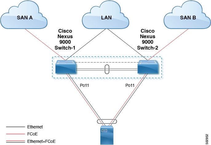
Cisco Nexus N9K-93180YC-FX、N9K-C9336C-FX2-E、および N9K-C93360YC-FX2 デバイスは vPC をサポートします。vPCscan は、帯域幅を増やし、イーサネット ファブリックへのロード バランシングを強化するように設定できます。次に、Cisco Nexus 9000 シリーズ スイッチで vPC を使用するときに FCoE を設定する方法を説明する設定例を示します。

図 5. ホスト vPC での FCoE トラフィック フロー
拡張 vPC での FCoE トラフィック フロー

(注)  

FCoE VLAN は、vPC ピア リンク間でトランキングしないでください。


(注)  

コア スイッチに接続する Cisco Nexus N9K スイッチ(スイッチモード)では、FC アップリンクのみがサポートされます。


設定例では、次のパラメータが含まれています。

switchname: tme-switch-1
switchname: tme-switch-2
mgmt ip: 172.25.182.66
mgmt ip: 172.25.182.67

設定例には、次のハードウェアが含まれています。

  • Emulex CNA または CISCO CNA

  • Cisco NX-OS リリース 10.2(1)F 以降のリリースを実行している 2 つの Cisco Nexus 9000 スイッチ。

設定例は次の考慮事項と要件を含んでいます。

  • DCBX をサポートする第 2 世代 CNA が必要です。

  • 別のスイッチへの単一のホスト CNA ポート チャネル接続。単一スイッチのポート チャネルで、ポート チャネルまたは vPC に複数のメンバー ポートが含まれている場合、FCoE インターフェイスは機能しません。

  • Cisco NX-OS リリース 10.2(1)F 以降のリリース。

Cisco Nexus 9000 シリーズ スイッチの vPC の設定例

この例では、基本設定(IP アドレス(mgmt0)、スイッチ名、管理者のパスワードなど)がスイッチで完了していると仮定します。


(注)  

設定は、vPC トポロジの両方のピア スイッチで実行する必要があります。


手順の概要

  1. feature vpc
  2. vPC domain
  3. vpc peer-link
  4. show vpc peer-keepalive
  5. int po
  6. vpc
  7. show vpc statistics

手順の詳細

  コマンドまたはアクション 目的
ステップ 1

feature vpc

例:

tme-switch-1# conf t
Enter configuration commands, one per line. End with CNTL/Z.
tme-switch-1(config)# feature vpc
tme-switch-1(config)#
 
tme-switch-2# conf t
Enter configuration commands, one per line. End with CNTL/Z.
tme-switch-2(config)# feature vpc
tme-switch-2(config)#

両方のピア スイッチで vPC 機能をイネーブルにします。

ステップ 2

vPC domain

例:

tme-switch-1(config)# vpc domain 2
tme-switch-1(config-vpc-domain)# peer-keepalive destination 192.165.200.230
 
tme-switch-2(config)# vpc domain 2
tme-switch-2(config-vpc-domain)# peer-keepalive destination 192.165.200.229

vPC ドメインおよびピアのキープアライブの宛先を設定します。

(注)   

この設定では、スイッチ tme-switch-1 の管理 IP アドレスは 192.165.200.229、スイッチ tme-switch-2 の管理 IP アドレスは 192.165.200.230 です。

ステップ 3

vpc peer-link

例:

tme-switch-1(config)# int port-channel 1
tme-switch-1(config-if)# vpc peer-link 
(注)   

vPC ピアリンクでは、スパニングツリー ポート タイプは、ネットワーク ポート タイプに変更されます。これにより、STP ブリッジ保証(デフォルトでイネーブル)がディセーブルでなければ、vPC ピアリンクの STP ブリッジ保証がイネーブルになります。


tme-switch-2(config)# int port-channel 1
tme-switch-2(config-if)# vpc peer-link 

vPC ピアリンクとして使用するポート チャネル インターフェイスを設定します。

ステップ 4

show vpc peer-keepalive

例:

tme-switch-1(config)# show vpc peer-keepalive
vPC keep-alive status : peer is alive
--Destination : 172.25.182.167
--Send status : Success
--Receive status : Success
--Last update from peer : (0) seconds, (975) msec
tme-switch-1(config)#
 
tme-switch-2(config)# show vpc peer-keepalive
--PC keep-alive status : peer is alive
--Destination : 172.25.182.166
--Send status : Success
--Receive status : Success
--Last update from peer : (0) seconds, (10336) msec
tme-switch-2(config)# 

ピア キープアライブに到達できることを確認します。

ステップ 5

int po

例:

tme-switch-1(config-if-range)# int po 1
tme-switch-1(config-if)# switchport mode trunk
tme-switch-1(config-if)# no shut
tme-switch-1(config-if)# exit
tme-switch-1(config)# int eth 1/39-40
tme-switch-1(config-if-range)# switchport mode trunk
tme-switch-1(config-if-range)# channel-group 1
tme-switch-1(config-if-range)# no shut
tme-switch-1(config-if-range)#
 
tme-switch-2(config-if-range)# int po 1
tme-switch-2(config-if)# switchport mode trunk
tme-switch-2(config-if)# no shut
tme-switch-2(config-if)# exit
tme-switch-2(config)# int eth 1/39-40
tme-switch-2(config-if-range)# switchport mode trunk
tme-switch-2(config-if-range)# channel-group 1
tme-switch-2(config-if-range)# no shut
tme-switch-2(config-if-range)#
 
tme-switch-1(config-if-range)# show int po1
port-channel 1 is up
Hardware: Port-Channel, address: 000d.ecde.a92f (bia 000d.ecde.a92f)
MTU 1500 bytes, BW 20000000 Kbit, DLY 10 usec,
reliability 255/255, txload 1/255, rxload 1/255
Encapsulation ARPA
Port mode is trunk
full-duplex, 10 Gb/s
Beacon is turned off
Input flow-control is off, output flow-control is off
Switchport monitor is off
Members in this channel: Eth1/39, Eth1/40
Last clearing of "show interface" counters never
1 minute input rate 1848 bits/sec, 0 packets/sec
1 minute output rate 3488 bits/sec, 3 packets/sec
tme-switch-1(config-if-range)#
 
tme-switch-2(config-if-range)# show int po1
port-channel1 is up
Hardware: Port-Channel, address: 000d.ecdf.5fae (bia 000d.ecdf.5fae) MTU 1500 bytes, BW 20000000 Kbit, DLY 10 usec,
reliability 255/255, txload 1/255, rxload 1/255
Encapsulation ARPA
Port mode is trunk
full-duplex, 10 Gb/s
Beacon is turned off
Input flow-control is off, output flow-control is off
Switchport monitor is off
Members in this channel: Eth1/39, Eth1/40
Last clearing of "show interface" counters never
minute input rate 1848 bits/sec, 0 packets/sec
minute output rate 3488 bits/sec, 3 packets/sec
tme-switch-2(config-if-range)# 

vPC ピア リンク ポート チャネルにメンバー ポートを追加し、このポート チャネル インターフェイスを起動します。

ステップ 6

vpc

例:
tme-switch-1(config)# int po 11
tme-switch-1(config-if)# vpc 11
tme-switch-1(config-if)# switchport mode trunk
tme-switch-1(config-if)# no shut
tme-switch-1(config-if)# int eth 1/1
tme-switch-1(config-if)# switchport mode trunk
tme-switch-1(config-if)# channel-group 11
tme-switch-1(config-if)# spanning-tree port type edge trunk
tme-switch-1(config-if)#
警告 

エッジ ポート タイプ(PortFast)は、単一のホストに接続されているポートだけでイネーブルにする必要があります。エッジ ポート タイプ(PortFast)がイネーブルの場合、このインターフェイスにハブ、コンセントレータ、スイッチ、ブリッジなどの一部のデバイスを接続すると、一時的なブリッジング ループが発生することがあります。このタイプの設定は、慎重に行う必要があります。

tme-switch-2(config)# int po 11
tme-switch-2(config-if)# vpc 11
tme-switch-2(config-if)# switchport mode trunk
tme-switch-2(config-if)# no shut
tme-switch-2(config-if)# int eth 1/1
tme-switch-2(config-if)# switchport mode trunk
tme-switch-2(config-if)# channel-group 11
tme-switch-2(config-if)# spanning-tree port type edge trunk
警告 

エッジ ポート タイプ(PortFast)は、単一のホストに接続されているポートだけでイネーブルにする必要があります。エッジ ポート タイプ(PortFast)がイネーブルの場合、このインターフェイスにハブ、コンセントレータ、スイッチ、ブリッジなどの一部のデバイスを接続すると、一時的なブリッジング ループが発生することがあります。このタイプの設定は、慎重に行う必要があります。

vPC を作成し、メンバー インターフェイスを追加します。

(注)   

vPC トポロジを介した FCoE を実行するには、ポート チャネルは単一のメンバー インターフェイスだけを持っている必要があります。

(注)   

ポート チャネル インターフェイスの下に設定された vPC 番号は、両方の Nexus 9000 スイッチで一致する必要があります。ポート チャネル インターフェイス番号が両方のスイッチで一致している必要はありません。

ステップ 7

show vpc statistics

例:
tme-switch-1(config-if)# show vpc statistics vpc 11
port-channel11 is up
vPC Status: Up, vPC number: 11
Hardware: Port-Channel, address: 000d.ecde.a908 (bia 000d.ecde.a908)
MTU 1500 bytes, BW 10000000 Kbit, DLY 10 usec,
reliability 255/255, txload 1/255, rxload 1/255
Encapsulation ARPA
Port mode is trunk
full-duplex, 10 Gb/s
Beacon is turned off
Input flow-control is off, output flow-control is off
Switchport monitor is off
Members in this channel: Eth1/1
Last clearing of "show interface" counters never
minute input rate 4968 bits/sec, 8 packets/sec
minute output rate 792 bits/sec, 1 packets/sec
tme-switch-1(config-if)#
 
tme-switch-2(config-if)# show vpc statistics vpc 11
port-channel11 is up
vPC Status: Up, vPC number: 11
Hardware: Port-Channel, address: 000d.ecdf.5fae (bia 000d.ecdf.5fae)
MTU 1500 bytes, BW 10000000 Kbit, DLY 10 usec,
reliability 255/255, txload 1/255, rxload 1/255
Encapsulation ARPA
Port mode is trunk
full-duplex, 10 Gb/s
Beacon is turned off
Input flow-control is off, output flow-control is off
Switchport monitor is off
Members in this channel: Eth1/1
Last clearing of "show interface" counters never
minute input rate 4968 bits/sec, 8 packets/sec
minute output rate 792 bits/sec, 1 packets/sec
tme-switch-1(config-if)#

vPC インターフェイスが起動していて、動作していることを確認します。

Cisco Nexus 9000 シリーズ スイッチの FCoE の設定例

2 つの Nexus 9000 スイッチ間に vPC をセットアップしたら、FCoE トポロジを設定できます。この手順では、IP アドレス(mgmt0)、スイッチ名、パスワード、管理者などを指定する基本設定が Nexus 9000 スイッチ上で実施済みであり、前のセクションに従って vPC 設定が完了していると想定しています。次の手順では、vPC トポロジとともに FCoE トポロジをセットアップするために必要な FCoE の基本設定を行います。

手順の概要

  1. install feature-set fcoe
  2. feature-set fcoe
  3. vsan database
  4. interface port-channel
  5. int vfc
  6. show int brief
  7. show flogi database
  8. show vpc statistics

手順の詳細

  コマンドまたはアクション 目的
ステップ 1

install feature-set fcoe

FCoE 機能をインストールします。

ステップ 2

feature-set fcoe

例:

tme-switch-1(config)# feature-set fcoe
Please configure the following for fcoe to be fully functional:
- hardware access-list tcam region ing-racl TCAM size
- hardware access-list tcam region ing-ifacl TCAM size
- hardware access-list tcam region ing-redirect TCAM size
tme-switch-1(config)#

tme-switch-2(config)# feature-set fcoe
Please configure the following for fcoe to be fully functional:
- hardware access-list tcam region ing-racl TCAM size
- hardware access-list tcam region ing-ifacl TCAM size
- hardware access-list tcam region ing-redirect TCAM size
tme-switch-2(config)#

Cisco Nexus 9000 スイッチで FCoE を有効にします。

(注)   

これが完了するまでに数分かかることがあります。この手順を実行する前に、TCAM カービングを完了する必要があります。TCAM カービングの完了後には、スイッチをリロードする必要があります。

ステップ 3

vsan database

例:
tme-switch-1(config)# vsan database
tme-switch-1(config-vsan-db)# vsan 100
tme-switch-1(config-vsan-db)# exit
tme-switch-1(config)# vlan 100
tme-switch-1(config-vlan)# fcoe vsan 100
tme-switch-1(config-vlan)# show vlan fcoe
VLAN VSAN Status
-------- -------- --------
100 100 Operational
tme-switch-1(config-vlan)#
 
tme-switch-2(config)# vsan database
tme-switch-2(config-vsan-db)# vsan 101
tme-switch-2(config-vsan-db)# exit
tme-switch-2(config)# vlan 101
tme-switch-2(config-vlan)# fcoe vsan 101
tme-switch-2(config-vlan)# show vlan fcoe
VLAN VSAN Status
-------- -------- --------
101 101 Operational
tme-switch-2(config)#

VSAN を構築して、FCoE トラフィックの伝送用として指定されている VLAN にマッピングします。

(注)   

VLAN 番号と VSAN 番号が同じである必要はありません。

ステップ 4

interface port-channel

例:

tme-switch-1(config)# interface port-channel 11
tme-switch-1(config-if)# switchport trunk allowed vlan 1, 100
tme-switch-1(config-if)# mtu 9216
tme-switch-1(config-if)# service-policy type qos input default-fcoe-in-policy
tme-switch-1(config-if)# show int trunk
------------------------------------------------------------------
Port Native Status Port
------------------------------------------------------------------
Eth1/1 1 trnk-bndl Po11
Eth1/39 1 trnk-bndl Po1
Eth1/40 1 trnk-bndl Po1
Po1 1 trunking --
Po11 1 trunking --
 
------------------------------------------------------------------
Port Vlans Allowed on Trunk
------------------------------------------------------------------
Eth1/1 1,100
Eth1/39 1-3967,4048-4093
Eth1/40 1-3967,4048-4093
Po1 1-3967,4048-4093
Po11 1,100
 
------------------------------------------------------------------
Port Vlans Err-disabled on Trunk
------------------------------------------------------------------
Eth1/1 none
Eth1/39 100
Eth1/40 100
Po1 100
Po11 none
 
------------------------------------------------------------------
Port STP Forwarding
------------------------------------------------------------------
Eth1/1 none
Eth1/39 none
Eth1/40 none
Po1 1
Po11 1,100
tme-switch-1(config-if)#
 
tme-switch-2(config)# int po 11
tme-switch-2(config-if)# switchport trunk allowed vlan 1, 101
tme-switch-1(config-if)# mtu 9216
tme-switch-1(config-if)# service-policy type qos input default-fcoe-in-policy
tme-switch-2(config-if)# show int trunk
------------------------------------------------------------------
Port Native Status Port
------------------------------------------------------------------
Eth1/1 1 trnk-bndl Po11
Eth1/39 1 trnk-bndl Po1
Eth1/40 1 trnk-bndl Po1
Po1 1 trunking --
Po11 1 trunking --
 
------------------------------------------------------------------
Port Vlans Allowed on Trunk
------------------------------------------------------------------
Eth1/1 1,101
Eth1/39 1-3967,4048-4093
Eth1/40 1-3967,4048-4093
Po1 1-3967,4048-4093
Po11 1,101
 
------------------------------------------------------------------
Port Vlans Err-disabled on Trunk
------------------------------------------------------------------
Eth1/1 none
Eth1/39 101
Eth1/40 101
Po1 101
Po11 none
 
------------------------------------------------------------------
Port STP Forwarding
------------------------------------------------------------------
Eth1/1 none
Eth1/39 none
Eth1/40 none
Po1 1
Po11 1,101
tme-switch-2(config-if)#

vPC リンクの通過を許可される VLAN を設定します。

ステップ 5

int vfc

例:

tme-switch-1(config)# int vfc 1
tme-switch-1(config-if)# bind interface po11
tme-switch-1(config-if)# no shut
tme-switch-1(config-if)#
 
tme-switch-2(config)# int vfc 1
tme-switch-2(config-if)# bind interface po11
tme-switch-2(config-if)# no shut
tme-switch-2(config-if)#
 
tme-switch-1(config)# vsan database
tme-switch-1(config-vsan-db)# vsan 100 interface vfc 1
tme-switch-1(config)# show vsan membership
vsan 1 interfaces:
fc2/1 fc2/2 fc2/3 fc2/4
fc2/5 fc2/6 fc2/7 fc2/8
 
vsan 100 interfaces:
vfc1
 
vsan 4079(evfp_isolated_vsan) interfaces:
 
vsan 4094(isolated_vsan) interfaces:
tme-switch-1(config)#
 
tme-switch-2(config)# vsan database
tme-switch-2(config-vsan-db)# vsan 101 interface vfc 1
tme-switch-2(config)# show vsan membership
vsan 1 interfaces:
fc2/1 fc2/2 fc2/3 fc2/4
fc2/5 fc2/6 fc2/7 fc2/8
 
vsan 101 interfaces:
vfc1
 
vsan 4079(evfp_isolated_vsan) interfaces:
 
vsan 4094(isolated_vsan) interfaces:
tme-switch-2(config)# 

仮想ファイバ チャネル インターフェイス(vfc)を構築し、前のステップで構築した VSAN に追加します。

ステップ 6

show int brief

例:

tme-switch-1(config-if)# show int brief
------------------------------------------------------------------
Ethernet VLAN Type Mode Status Reason Speed
------------------------------------------------------------------
Eth1/1 1 eth trunk up none 10G(D)
Eth1/2 1 eth access up none 10G(D)
Eth1/38 1 eth access down SFP not inserted 10G(D)
Eth1/39 1 eth trunk up none 10G(D)
Eth1/40 1 eth trunk up none 10G(D)
 
------------------------------------------------------------------
Port-channel VLAN Type Mode Status Reason Speed
------------------------------------------------------------------
Po1 1 eth trunk up none a-10G(D) none
Po11 1 eth trunk up none a-10G(D) none
 
------------------------------------------------------------------
Port VRF Status IP Address Speed MTU
------------------------------------------------------------------
mgmt0 -- up 172.25.182.166 1000 1500
 
------------------------------------------------------------------
Interface Vsan Admin Admin Status SFP Oper Oper Port
------------------------------------------------------------------
vfc1 100 F on up -- F auto --
tme-switch-1(config-if)#
 
tme-switch-2(config-if)# show int brief
------------------------------------------------------------------
Ethernet VLAN Type Mode Status Reason Speed Port
------------------------------------------------------------------
Eth1/1 1 eth trunk up none 10G(D) 11
Eth1/2 1 eth access up none 10G(D) --
Eth1/38 1 eth access down SFP not inserted 10G(D) --
Eth1/39 1 eth trunk up none 10G(D) 1
Eth1/40 1 eth trunk up none 10G(D) 1
 
------------------------------------------------------------------
Port-channel VLAN Type Mode Status Reason Speed Protocol
------------------------------------------------------------------
Po1 1 eth trunk up none a-10G(D) none
Po11 1 eth trunk up none a-10G(D) none
 
------------------------------------------------------------------
Port VRF Status IP Address Speed MTU
------------------------------------------------------------------
mgmt0 -- up 172.25.182.167 1000 1500
 
------------------------------------------------------------------
Interface Vsan Admin Admin Status SFP Oper Oper
------------------------------------------------------------------
vfc1 101 F on up -- F auto --
tme-switch-2(config-if)#
 

vfc が起動し、動作していることを確認します。

ステップ 7

show flogi database

例:
tme-switch-1# show flogi database
------------------------------------------------------------------
INTERFACE VSAN FCID PORT NAME NODE NAME
-----------------------------------------------------------------------
vfc1 100 0x540000 21:00:00:c0:dd:11:2a:01 20:00:00:c0:dd:11:2a:01
 
Total number of flogi = 1.
tme-switch-2# show flogi database
-----------------------------------------------------------------------
INTERFACE VSAN FCID PORT NAME NODE NAME
------------------------------------------------------------------------
vfc1 101 0x540000 21:00:00:c0:dd:11:2a:01 20:00:00:c0:dd:11:2a:01
 
Total number of flogi = 1.

仮想ファイバ チャネル インターフェイスがファブリックにログインしたことを確認します。

ステップ 8

show vpc statistics

例:
tme-switch-1(config-if)# show vpc statistics vpc 11
port-channel11 is up
vPC Status: Up, vPC number: 11
Hardware: Port-Channel, address: 000d.ecde.a908 (bia 000d.ecde.a908)
MTU 1500 bytes, BW 10000000 Kbit, DLY 10 usec,
reliability 255/255, txload 1/255, rxload 1/255
Encapsulation ARPA
Port mode is trunk
full-duplex, 10 Gb/s
Beacon is turned off
Input flow-control is off, output flow-control is off
Switchport monitor is off
Members in this channel: Eth1/1
Last clearing of "show interface" counters never
1 minute input rate 4968 bits/sec, 8 packets/sec
1 minute output rate 792 bits/sec, 1 packets/sec
 
tme-switch-2(config-if)# show vpc statistics vpc 11
port-channel11 is up
vPC Status: Up, vPC number: 11
Hardware: Port-Channel, address: 000d.ecdf.5fae (bia 000d.ecdf.5fae)
MTU 1500 bytes, BW 10000000 Kbit, DLY 10 usec,
reliability 255/255, txload 1/255, rxload 1/255
Encapsulation ARPA
Port mode is trunk
full-duplex, 10 Gb/s
Beacon is turned off
Input flow-control is off, output flow-control is off
Switchport monitor is off
Members in this channel: Eth1/1
Last clearing of "show interface" counters never
1 minute input rate 4968 bits/sec, 8 packets/sec
1 minute output rate 792 bits/sec, 1 packets/sec
 

vPC が起動し、動作していることを確認します。