IOS-XEでのPIM-SMを使用したマルチキャストサービスリフレクション:マルチキャストからユニキャスト
ダウンロード オプション
偏向のない言語
この製品のドキュメントセットは、偏向のない言語を使用するように配慮されています。このドキュメントセットでの偏向のない言語とは、年齢、障害、性別、人種的アイデンティティ、民族的アイデンティティ、性的指向、社会経済的地位、およびインターセクショナリティに基づく差別を意味しない言語として定義されています。製品ソフトウェアのユーザインターフェイスにハードコードされている言語、RFP のドキュメントに基づいて使用されている言語、または参照されているサードパーティ製品で使用されている言語によりドキュメントに例外が存在する場合があります。シスコのインクルーシブ ランゲージの取り組みの詳細は、こちらをご覧ください。
翻訳について
シスコは世界中のユーザにそれぞれの言語でサポート コンテンツを提供するために、機械と人による翻訳を組み合わせて、本ドキュメントを翻訳しています。ただし、最高度の機械翻訳であっても、専門家による翻訳のような正確性は確保されません。シスコは、これら翻訳の正確性について法的責任を負いません。原典である英語版(リンクからアクセス可能)もあわせて参照することを推奨します。
はじめに
この記事の目的は、設定ラボガイドの形式を通じて、IOS-XEプラットフォームを使用したMSR(Multicast Service Replication)の基本的な動作を理解していただくことです。
前提条件
要件
PIM-SMに関する基礎知識
使用するコンポーネント
ASR1000(R2およびR4)、ISR4300(R3)、ISR2900(R1およびR5)
設定
マルチキャストを変換するための以下の図のシナリオに基づいて、以下のエンドツーエンド設定を示します。
ネットワーク図
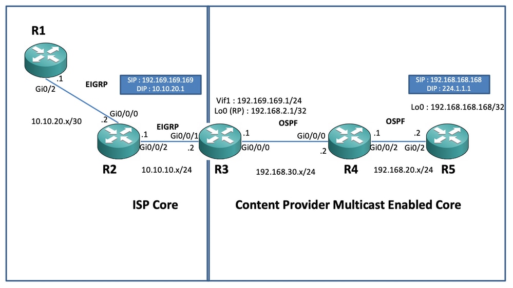
コンフィギュレーション
上記の図では、ノードR1が、マルチキャストソースからユニキャストマルチキャストデータフィードのみを取得することになっているレシーバとして機能します。
ノードR5はマルチキャストソースとして機能し、ループバック0インターフェイスから送信されるマルチキャストICMPトラフィックを生成します。
ノードR2はコンテンツプロバイダーマルチキャストコアドメインの下にあり、OSPFのアンダーレイでPIM-SMを実行しています。
ノードR3は、Multicast Service Replication Application(MSRP)を実行するルータとして機能します。この例では、マルチキャストデータトラフィックの起点となるマルチキャスト境界ルータが、受信側に向けてユニキャストデータパケットに変換されます。このルータは、コンテンツプロバイダー(CP)とISPとそれぞれOSPFとEIGRPを使用し、マルチキャストコアドメイン内のループバックインターフェイス上にRP(ランデブーポイント)を収容します。
ノードR4はISPのコア制御下にあり、マルチキャストは有効になっていないため、アンダーレイEIGRPルーティングを使用してR3ノードに到達する方法のみを理解しています。
次に、上記のトポロジ図にあるノードに関連する設定を示します(図1を参照)。
R1:
!
no ip domain lookup
ip cef
no ipv6 cef
!
interface GigabitEthernet0/2
 ip address 10.10.20.1 255.255.255.0
 duplex auto
 speed auto
end
!
router eigrp 100
 network 10.10.20.0 0.0.0.255
!
R2:
!
interface GigabitEthernet0/0/0
 ip address 10.10.20.2 255.255.255.0
 negotiation auto
!
interface GigabitEthernet0/0/2
 ip address 10.10.10.1 255.255.255.0
 negotiation auto
!
router eigrp 100
 network 10.10.10.0 0.0.0.255
 network 10.10.20.0 0.0.0.255
!
R3:
!
ip multicast-routing distributed
!
interface Loopback0
 ip address 192.168.2.1 255.255.255.255
 ip pim sparse-mode
 ip ospf 1 area 0
!
interface GigabitEthernet0/0/0
 ip address 192.168.30.1 255.255.255.0
 ip pim sparse-mode
 ip ospf 1 area 0
 negotiation auto
!
interface GigabitEthernet0/0/1
 ip address 10.10.10.2 255.255.255.0
 negotiation auto
!
interface Vif1
 ip address 192.169.169.1 255.255.255.0
 ip pim sparse-mode
 ip service reflect GigabitEthernet0/0/0 destination 224.1.1.0 to 10.10.20.0 mask-len 24 source 192.169.169.169 <<<<
 ip igmp static-group 224.1.1.1
 ip ospf 1 area 0
!
router eigrp 100
 network 10.10.10.0 0.0.0.255
!
router ospf 1
!
ip pim rp-address 192.168.2.1
!
R4:
!
ip multicast-routing distributed
!
interface GigabitEthernet0/0/0
 ip address 192.168.30.2 255.255.255.0
 ip pim sparse-mode
 ip ospf 1 area 0
 negotiation auto
!
interface GigabitEthernet0/0/2
 ip address 192.168.20.1 255.255.255.0
 ip pim sparse-mode
 ip ospf 1 area 0
 negotiation auto
!
router ospf 1
!
ip pim rp-address 192.168.2.1
!
R5:
!
ip multicast-routing
ip cef
no ipv6 cef
!
interface Loopback0
 ip address 192.168.168.168 255.255.255.255
 ip pim sparse-mode
 ip ospf 1 area 0
!
interface GigabitEthernet0/2
 ip address 192.168.20.2 255.255.255.0
 ip pim sparse-mode
 ip ospf 1 area 0
 duplex auto
 speed auto
!
router ospf 1
!
ip pim rp-address 192.168.2.1
!
確認
R5ルータからのマルチキャストトラフィックをシミュレートするために、ループバック0インターフェイス[192.168.168.168]の送信元からマルチキャストアドレス224.1.1.1宛てにテストpingを実行することで、設定を検証できます。次に、MSRアプリケーションを実行しているノード(R3)のmrouteエントリを確認します。
R5(config)#do ping 224.1.1.1 sou lo 0 rep 10000000
Type escape sequence to abort.
Sending 10000000, 100-byte ICMP Echos to 224.1.1.1, timeout is 2 seconds:
Packet sent with a source address of 192.168.168.168
.............................
R3#sh ip mroute 224.1.1.1
IP Multicast Routing Table
Flags: D - Dense, S - Sparse, B - Bidir Group, s - SSM Group, C - Connected,
L - Local, P - Pruned, R - RP-bit set, F - Register flag,
T - SPT-bit set, J - Join SPT, M - MSDP created entry, E - Extranet,
X - Proxy Join Timer Running, A - Candidate for MSDP Advertisement,
U - URD, I - Received Source Specific Host Report,
Z - Multicast Tunnel, z - MDT-data group sender,
Y - Joined MDT-data group, y - Sending to MDT-data group,
G - Received BGP C-Mroute, g - Sent BGP C-Mroute,
N - Received BGP Shared-Tree Prune, n - BGP C-Mroute suppressed,
Q - Received BGP S-A Route, q - Sent BGP S-A Route,
V - RD & Vector, v - Vector, p - PIM Joins on route,
x - VxLAN group, c - PFP-SA cache created entry
Outgoing interface flags: H - Hardware switched, A - Assert winner, p - PIM Join
Timers: Uptime/Expires
Interface state: Interface, Next-Hop or VCD, State/Mode
(*, 224.1.1.1), 00:47:41/stopped, RP 192.168.2.1, flags: SJC
Incoming interface: Null, RPF nbr 0.0.0.0
Outgoing interface list:
Vif1, Forward/Sparse, 00:46:36/00:01:23 <<<<
(192.168.168.168, 224.1.1.1), 00:00:20/00:02:43, flags: T
Incoming interface: GigabitEthernet0/0/0, RPF nbr 192.168.30.2
Outgoing interface list:
Vif1, Forward/Sparse, 00:00:20/00:02:39 <<<<R3#sh ip mroute 224.1.1.1 count
Use "show ip mfib count" to get better response time for a large number of mroutes.
IP Multicast Statistics
3 routes using 2938 bytes of memory
2 groups, 0.50 average sources per group
Forwarding Counts: Pkt Count/Pkts per second/Avg Pkt Size/Kilobits per second
Other counts: Total/RPF failed/Other drops(OIF-null, rate-limit etc)
Group: 224.1.1.1, Source count: 1, Packets forwarded: 1455, Packets received: 1458 <<<<
RP-tree: Forwarding: 1/0/100/0, Other: 1/0/0
Source: 192.168.168.168/32, Forwarding: 1454/1/113/0, Other: 1457/3/0
R3#sh ip mroute 224.1.1.1 count
Use "show ip mfib count" to get better response time for a large number of mroutes.
IP Multicast Statistics
3 routes using 2938 bytes of memory
2 groups, 0.50 average sources per group
Forwarding Counts: Pkt Count/Pkts per second/Avg Pkt Size/Kilobits per second
Other counts: Total/RPF failed/Other drops(OIF-null, rate-limit etc)
Group: 224.1.1.1, Source count: 1, Packets forwarded: 1465, Packets received: 1468 <<<<
RP-tree: Forwarding: 1/0/100/0, Other: 1/0/0
Source: 192.168.168.168/32, Forwarding: 1464/1/113/0, Other: 1467/3/0また、IOS-XEルータのEPC(Embedded Packet Capture)機能を使用して、パケットがR2ノードで目的のユニキャスト宛先アドレスに実際に変換されていることを確認するためのキャプチャを取得することもできます(R1のユニキャスト宛先アドレスの変換に使用)。
R2#mon cap TAC int gi 0/0/2 both match any
R2#mon cap TAC buff siz 50 circular
R2#mon cap TAC start
Started capture point : TAC
R2#
*Aug 12 06:50:40.195: %BUFCAP-6-ENABLE: Capture Point TAC enabled.
R2#sh mon cap TAC buff br | i ICMP
   6  114   10.684022   192.169.169.169  ->  10.10.20.1       0  BE   ICMP <<<<
   7  114   10.684022   192.169.169.169  ->  10.10.20.1       0  BE   ICMP <<<<
   8  114   12.683015   192.169.169.169  ->  10.10.20.1       0  BE   ICMP <<<<
   9  114   12.683015   192.169.169.169  ->  10.10.20.1       0  BE   ICMP <<<<
ここで注意すべき重要な点は、「ラボ環境」でマルチキャストICMP PINGを実行する場合、通常は、2つの(送信元と受信側)の間に完全な到達可能性があると仮定して、ICMPエコー応答パケットを受信側から送信元に向けて返信することを期待するということです。 ただし、このシナリオでは、マルチキャストICMPパケットのNATされた送信元アドレス(192.169.169.169)を受信側(EIGRP経由でR1)までアドバタイズしようとしても、逆NATがMSRアプリケーションノードで設定されていないため、ユニキャストICMPエコー応答はR3ルータを通過しないことに注意することが重要です。これをテストするには、R3でEIGRP(ISPコアルーティング)へのVif 1インターフェイスのEIGRPルートアドバタイズメントを実行します。
ISR4351(config)#router eigrp 100
ISR4351(config-router)#network 192.169.169.0 0.0.0.255 <<<<
ここで、R3に向けて送信されているICMPエコー応答に関して、R2ノードで取得されたキャプチャを確認できます(R1のキャプチャは送信されていません)。
R2#sh mon cap TAC buff br | i ICMP

 249  114  317.847948   192.169.169.169  ->  10.10.20.1       0  BE   ICMP
 250  114  317.847948   192.169.169.169  ->  10.10.20.1       0  BE   ICMP
 251  114  317.847948   10.10.20.1       ->  192.169.169.169  0  BE   ICMP <<<<
 252  114  317.847948   10.10.20.1       ->  192.169.169.169  0  BE   ICMP <<<<
 253  114  319.847948   192.169.169.169  ->  10.10.20.1       0  BE   ICMP
 254  114  319.847948   192.169.169.169  ->  10.10.20.1       0  BE   ICMP
 255  114  319.848955   10.10.20.1       ->  192.169.169.169  0  BE   ICMP <<<<
 256  114  319.848955   10.10.20.1       ->  192.169.169.169  0  BE   ICMP <<<<
 259  114  321.848955   192.169.169.169  ->  10.10.20.1       0  BE   ICMP
 260  114  321.848955   192.169.169.169  ->  10.10.20.1       0  BE   ICMP
 261  114  321.848955   10.10.20.1       ->  192.169.169.169  0  BE   ICMP <<<<
 262  114  321.848955   10.10.20.1       ->  192.169.169.169  0  BE   ICMP <<<<
ただし、発信元R5で見られるように、pingは失敗します。
R5(config)#do ping 224.1.1.1 sou lo 0 rep 10000000
Type escape sequence to abort.
Sending 10000000, 100-byte ICMP Echos to 224.1.1.1, timeout is 2 seconds:
Packet sent with a source address of 192.168.168.168
......................................................................
......................................................................
ここで、送信元まで到達する応答を取得するため、拡張可能なNAT(Extendable NAT)を設定して、宛先の192.169.169.169宛てのトラフィックを192.168.168.168に変換するようにMSRアプリケーションノードR3でNATポートフォワーディングを設定します。
R3(config)#int gi 0/0/1
R3(config-if)#ip nat out
R3(config-if)#int gi 0/0/0
R3(config-if)#ip nat ins
R3(config-if)#exit
R3(config)#ip nat inside source static 192.168.168.168 192.169.169.169 extendable <<<<
ここで送信元R5ノードを確認すると、応答が返ってくることがわかります(R5の応答はRPから返されます)。
R5(config)#do ping 224.1.1.1 sou lo 0 rep 10000000
Type escape sequence to abort.
Sending 10000000, 100-byte ICMP Echos to 224.1.1.1, timeout is 2 seconds:
Packet sent with a source address of 192.168.168.168
......................................................................

Reply to request 716 from 10.10.20.1, 1 ms
Reply to request 716 from 10.10.20.1, 1 ms
Reply to request 717 from 10.10.20.1, 1 ms
Reply to request 717 from 10.10.20.1, 1 ms
Reply to request 718 from 10.10.20.1, 1 ms
Reply to request 718 from 10.10.20.1, 1 ms
上記は、パケットフローを説明し、データトラフィックとダウンストリームマルチキャストトラフィックに対して逆ユニキャストパス/フローを確立する方法を理解するために実行されました。通常の実稼働シナリオでは、サーバ/ソース側で実行されているマルチキャストアプリケーションがユニキャスト形式の受信者からの逆方向確認応答パケットを必要とするケースやインスタンスには、通常は該当しません。
上記のテストと検証により、マルチキャスト境界ノードの1つでマルチキャストサービスレプリケーションアプリケーションを実行する方法と、上記のテストと検証を大規模な展開に展開する場合にマルチキャストサービスレプリケーションアプリケーションを展開する方法について、簡単な概要が提供されるはずです。
 フィードバック