- Preface
- Chapter 1 - Overview
- Chapter 2 - Installing the Hardware
- Chapter 3 - Installing the Software
- Chapter 4 - Utilities
- Chapter 5 - Error Messages and Trouble Shooting
- Appendix A - Technical Specifications
- Appendix B - Channels, Power Levels, Antenna Gains
- Appendix C - Declarations of Conformity and Regulatory Information
- Appendix D - Translated Safety Warnings
- Index
Cisco Aironet Wireless LAN Client Adapters Installation and Configuration Guide for MS-DOS
Bias-Free Language
The documentation set for this product strives to use bias-free language. For the purposes of this documentation set, bias-free is defined as language that does not imply discrimination based on age, disability, gender, racial identity, ethnic identity, sexual orientation, socioeconomic status, and intersectionality. Exceptions may be present in the documentation due to language that is hardcoded in the user interfaces of the product software, language used based on RFP documentation, or language that is used by a referenced third-party product. Learn more about how Cisco is using Inclusive Language.
- Updated:
- May 4, 2007
Chapter: Chapter 2 - Installing the Hardware
Installing the Hardware
This section describes the procedures for installing the Cisco Aironet Wireless LAN Client Adapter.
These topics are covered in this section:
•![]() Inserting the Client Adapter into a Computing Device
Inserting the Client Adapter into a Computing Device
Safety Information
Follow the guidelines in this section to ensure proper operation and safe use of the client adapter.
FCC Safety Compliance Statement
The FCC, with its action in ET Docket 96-8, has adopted a safety standard for human exposure to RF electromagnetic energy emitted by FCC-certified equipment. Cisco Aironet products meet the uncontrolled environmental limits found in OET-65 and ANSI C95.1, 1991. Proper operation of this radio device according to the instructions in this publication will result in user exposure substantially below the FCC recommended limits.
Safety Guidelines
•![]() Do not touch or move the antenna while the unit is transmitting or receiving.
Do not touch or move the antenna while the unit is transmitting or receiving.
•![]() Do not hold any component containing a radio such that the antenna is very close to or touching any exposed parts of the body, especially the face or eyes, while transmitting.
Do not hold any component containing a radio such that the antenna is very close to or touching any exposed parts of the body, especially the face or eyes, while transmitting.
•![]() Do not operate the radio or attempt to transmit data unless the antenna is connected; otherwise, the radio can be damaged.
Do not operate the radio or attempt to transmit data unless the antenna is connected; otherwise, the radio can be damaged.
•![]() Use in specific environments:
Use in specific environments:
–![]() The use of wireless devices in hazardous locations is limited to the constraints posed by the safety directors of such environments.
The use of wireless devices in hazardous locations is limited to the constraints posed by the safety directors of such environments.
–![]() The use of wireless devices on airplanes is governed by the Federal Aviation Administration (FAA).
The use of wireless devices on airplanes is governed by the Federal Aviation Administration (FAA).
–![]() The use of wireless devices in hospitals is restricted to the limits set forth by each hospital.
The use of wireless devices in hospitals is restricted to the limits set forth by each hospital.
•![]() Antenna use:
Antenna use:
–![]() To comply with FCC RF exposure limits, dipole antennas should be located at a minimum distance of 7.9 inches (20 cm) or more from the body of all persons.
To comply with FCC RF exposure limits, dipole antennas should be located at a minimum distance of 7.9 inches (20 cm) or more from the body of all persons.
–![]() High-gain, wall-mount, or mast-mount antennas are designed to be professionally installed and should be located at a minimum distance of 12 inches (30 cm) or more from the body of all persons. Please contact your professional installer, VAR, or antenna manufacturer for proper installation requirements.
High-gain, wall-mount, or mast-mount antennas are designed to be professionally installed and should be located at a minimum distance of 12 inches (30 cm) or more from the body of all persons. Please contact your professional installer, VAR, or antenna manufacturer for proper installation requirements.
Warnings
Observe the following warnings when operating the client adapter:

Warning ![]() Do not operate your wireless network device near unshielded blasting caps or in an explosive environment unless the device has been modified to be especially qualified for such use.
Do not operate your wireless network device near unshielded blasting caps or in an explosive environment unless the device has been modified to be especially qualified for such use.
Warning ![]() In order to comply with RF exposure limits established in the ANSI C95.1 standards, it is recommended when using a laptop with a PC card client adapter that the adapter's integrated antenna is positioned more than 2 inches (5 cm) from your body or nearby persons during extended periods of transmitting or operating time. If the antenna is positioned less than 2 inches (5 cm) from the user, it is recommended that the user limit exposure time.
In order to comply with RF exposure limits established in the ANSI C95.1 standards, it is recommended when using a laptop with a PC card client adapter that the adapter's integrated antenna is positioned more than 2 inches (5 cm) from your body or nearby persons during extended periods of transmitting or operating time. If the antenna is positioned less than 2 inches (5 cm) from the user, it is recommended that the user limit exposure time.
Translated versions of these safety warnings are provided in Appendix D.
Other Devices in the Wireless Network
Refer to the user's guide and technical reference manual for the access point, universal client, or bridge for additional information.
Unpacking the Client Adapter
Follow these steps to unpack the client adapter:
Step 1 ![]() Open the shipping container, and carefully remove the contents.
Open the shipping container, and carefully remove the contents.
Step 2 ![]() Return all packing materials to the shipping container, and save it.
Return all packing materials to the shipping container, and save it.
Step 3 ![]() Ensure that all items listed in the "Package Contents" section are included in the shipment. Check each item for damage.
Ensure that all items listed in the "Package Contents" section are included in the shipment. Check each item for damage.

Note ![]() If any item is damaged or missing, notify your authorized Cisco sales representative. Any remote antenna and its associated wiring are shipped separately.
If any item is damaged or missing, notify your authorized Cisco sales representative. Any remote antenna and its associated wiring are shipped separately.
Package Contents
Each client adapter is shipped with the following items:
•![]() Cisco Aironet PC Card Client Adapter, Cisco Aironet LM Card Client Adapter, or Cisco Aironet PCI Client Adapter
Cisco Aironet PC Card Client Adapter, Cisco Aironet LM Card Client Adapter, or Cisco Aironet PCI Client Adapter
•![]() 2-dBi dipole antenna (for PCI client adapter)
2-dBi dipole antenna (for PCI client adapter)
•![]() Quick Start Guide: Cisco Aironet Wireless LAN Client Adapters
Quick Start Guide: Cisco Aironet Wireless LAN Client Adapters
•![]() Cisco Aironet Series Wireless LAN Client Adapters Drivers and Utilities CD
Cisco Aironet Series Wireless LAN Client Adapters Drivers and Utilities CD
•![]() Cisco product registration card
Cisco product registration card
Note ![]() The MS-DOS drivers and utilities are not shipped with the adapter. Follow this path to download them from Cisco.com: Service & Support > Technical Assistance Center > Software Center > Wireless Software.
The MS-DOS drivers and utilities are not shipped with the adapter. Follow this path to download them from Cisco.com: Service & Support > Technical Assistance Center > Software Center > Wireless Software.
Antenna Connectors
The LM card version has two female MicroMate (also called MMCX ) antenna connectors on one end. See Figure 2-1. All antennas and cables attached to the adapter must be equipped with male MicroMate connectors.
The two antenna connectors allow a Diversity Antenna or two separate antennas to be attached to the Cisco Aironet Wireless LAN Adapter. When two antennas are connected, the adapter automatically selects antennas to provide the strongest signal for radio operations. This feature improves packet delivery and system throughput by avoiding reception and transmission instances that are hampered by RF multipath signals or blocking structures in the environment.
Figure 2-1 LM Adapter Antenna Connections

Attaching a Remote Antenna
Note ![]() The PCM version of the adapter comes with the antenna installed. If you need to remove or change the antenna, remove the adapter from the PC card slot.
The PCM version of the adapter comes with the antenna installed. If you need to remove or change the antenna, remove the adapter from the PC card slot.
Step 1 ![]() Line up the antenna cable leads with the connectors on the adapter.
Line up the antenna cable leads with the connectors on the adapter.
Step 2 ![]() Slide the cable leads into the connectors until they snap into place.
Slide the cable leads into the connectors until they snap into place.
Note ![]() The J1 port is the primary port. If the antenna has only 1 MMCX connector, attach it to the J1 port.
The J1 port is the primary port. If the antenna has only 1 MMCX connector, attach it to the J1 port.
Detaching a Remote Antenna
Step 1 ![]() Remove the adapter from the PC card slot.
Remove the adapter from the PC card slot.
Step 2 ![]() Grasp the end of the antenna cable lead by the connector.
Grasp the end of the antenna cable lead by the connector.
Step 3 ![]() Gently pull the connector away from the adapter until it comes free.
Gently pull the connector away from the adapter until it comes free.
Inserting the Client Adapter into a Computing Device
This section provides instructions for inserting a PC card or a PCI client adapter into a computing device.

Inserting a PC Card
Step 1 ![]() Before you begin, examine the PC card. One end has a dual-row, 68-pin PC card connector. The card is keyed so that it can be inserted only one way into the PC card slot.
Before you begin, examine the PC card. One end has a dual-row, 68-pin PC card connector. The card is keyed so that it can be inserted only one way into the PC card slot.
Step 2 ![]() Turn on your computer, let the operating system boot up completely, and follow the remaining steps in this section to insert the PC card.
Turn on your computer, let the operating system boot up completely, and follow the remaining steps in this section to insert the PC card.
Step 3 ![]() Hold the PC card with the Cisco logo facing up and insert it into the PC card slot, applying just enough pressure to make sure it is fully seated. See Figure 2-2.
Hold the PC card with the Cisco logo facing up and insert it into the PC card slot, applying just enough pressure to make sure it is fully seated. See Figure 2-2.
Figure 2-2
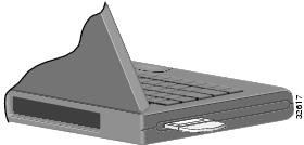
Inserting a PC Card into a Computing Device
Note ![]() You can remove and reinsert your PC card when necessary. See the "Removing the Client Adapter" section for instructions.
You can remove and reinsert your PC card when necessary. See the "Removing the Client Adapter" section for instructions.
Inserting a PCI Client Adapter
Step 1 ![]() Turn off the PC and all its components.
Turn off the PC and all its components.
Step 2 ![]() Remove the computer cover.
Remove the computer cover.
On most Pentium PCs, PCI expansion slots are white. Refer to your PC documentation for slot identification.
Step 3 ![]() Remove the screw from the top of the CPU back panel above an empty PCI expansion slot. This screw holds the metal bracket on the back panel.
Remove the screw from the top of the CPU back panel above an empty PCI expansion slot. This screw holds the metal bracket on the back panel.
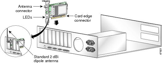
Step 4 ![]() Examine the client adapter. The antenna connector and the LEDs face out of your computer and are visible when you put the cover back on. The bottom edge of the adapter is the connector that you will insert into an empty expansion slot in your computer. See Figure 2-3.
Examine the client adapter. The antenna connector and the LEDs face out of your computer and are visible when you put the cover back on. The bottom edge of the adapter is the connector that you will insert into an empty expansion slot in your computer. See Figure 2-3.
Figure 2-3 Inserting a PCI Client Adapter into a PC
Step 5 ![]() Tilt the adapter to allow the antenna connector and LEDs to slip through the opening in the CPU back panel.
Tilt the adapter to allow the antenna connector and LEDs to slip through the opening in the CPU back panel.
Step 6 ![]() Press the client adapter into the empty slot until the connector is firmly seated.
Press the client adapter into the empty slot until the connector is firmly seated.
Step 7 ![]() Reinstall the screw on the CPU back panel, and replace the computer cover.
Reinstall the screw on the CPU back panel, and replace the computer cover.
Step 8 ![]() Attach the 2-dBi antenna to the adapter's antenna connector until it is finger-tight. Do not overtighten.
Attach the 2-dBi antenna to the adapter's antenna connector until it is finger-tight. Do not overtighten.
Step 9 ![]() For optimal reception, position the antenna so that it is straight up.
For optimal reception, position the antenna so that it is straight up.
Step 10 ![]() Boot up your computer.
Boot up your computer.
Note ![]() Because PCI adapters are installed inside desktop computers, you should have little reason to remove the adapter. However, instructions are provided in the "Removing the Client Adapter" section on page 7-7 in case you ever need to remove your PCI client adapter.
Because PCI adapters are installed inside desktop computers, you should have little reason to remove the adapter. However, instructions are provided in the "Removing the Client Adapter" section on page 7-7 in case you ever need to remove your PCI client adapter.
Removing the Client Adapter
Follow the instructions in this section whenever you need to remove the client adapter from your computer.
Removing a PC Card
To remove a PC card after it is successfully installed and configured (such as when your laptop is to be transported), pull the card directly out of the PC card slot. The client adapter is "hot swappable" and can be inserted and ejected at any time after you have installed the driver.
Removing a PCI Client Adapter
Because a PCI adapters are installed inside desktop computers, which are not designed for portable use, you should have little reason to remove the adapter. Follow these steps in case you ever need to remove your PCI client adapter.
Step 1 ![]() Completely shut down your computer.
Completely shut down your computer.
Note ![]() When the computer is turned off by using the power switch, there still might be power supplied to the motherboard. To ensure that your computer is completely shut down, unplug the computer's power cord from its power source.
When the computer is turned off by using the power switch, there still might be power supplied to the motherboard. To ensure that your computer is completely shut down, unplug the computer's power cord from its power source.
Step 2 ![]() Disconnect the client adapter's antenna.
Disconnect the client adapter's antenna.
Step 3 ![]() Remove the computer cover.
Remove the computer cover.
Step 4 ![]() Remove the screw from the top of the CPU back panel above the PCI expansion slot that holds your client adapter.
Remove the screw from the top of the CPU back panel above the PCI expansion slot that holds your client adapter.
Step 5 ![]() Pull up firmly on the client adapter to release it from the slot, and carefully tilt the adapter to allow it to clear the opening in the CPU back panel.
Pull up firmly on the client adapter to release it from the slot, and carefully tilt the adapter to allow it to clear the opening in the CPU back panel.
Step 6 ![]() Reinstall the screw on the CPU back panel, and replace the computer cover.
Reinstall the screw on the CPU back panel, and replace the computer cover.
 Feedback