Cisco IW-PWRADPT-MFITHZ= Power Supply Unit Installation Guide
This document describes the Cisco IW-PWRADPT-MFITHZ= Power Supply Assembly (referred to as the power supply or PSU in this document) and provides instructions for its assembly and mounting.
Overview
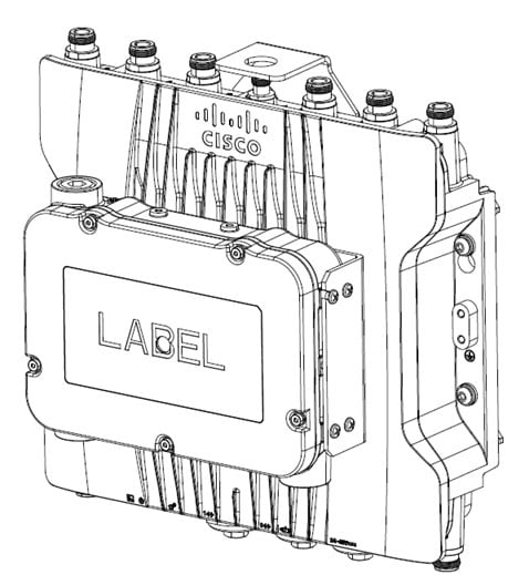
The Cisco power supply model IW-PWRADPT-MFITHZ= is an outdoor, single-phase AC/DC PSU with a 60-Watt output. It delivers a DC voltage output of 48V and operates within the input range of 100–240 VAC. The protective case encloses the AC/DC power unit to ensure safe operation in hazardous locations. The PSU must be used with ½" NPT cable glands that comply with IECEx certification standards.
Mount the PSU individually on each supporting Cisco AP.
Unpacking the PSU Package
The following items are shipped in the package.
-
PSU in a case.
If any item is missing or damaged, contact your Cisco representative or reseller.
Technical Specifications
This table lists specifications for the power supply:
|
Specification |
IW-PWRADPT-MFITHZ= |
|---|---|
|
Input-voltage range and frequency |
AC input: 100-240V, 50-60Hz (nominal) |
|
Output voltage and current |
48 VDC, 1.25A, 60 W Max |
|
Physical specification |
Dimensions (W x H x L): 155 mm x 49.7 mm x 204.2 mm |
|
Weight |
1.76 Kgs (3.88 lbs) ±10% |
|
Operating temperature |
-40°C to +70°C, still air condition including solar loading |
|
Non-operating temperature |
-40°C to +85°C |
|
Humidity |
Operating: 5% to 95%, condensing is allowed outside of adapter Non-operating: 5% to 95%, condensing is allowed outside of adapter IP67 Rated |
|
Thermal shock |
Operating thermal shock: -40°C to + 70°C at 0.5°C per minute Non-operating thermal shock: -40°C to +85°C, with change over time between 2 and 3 minutes |
|
Altitude |
Operating altitude: -500 to 17,000 feet from sea level Non-operating altitude:-1,000 to 30,000 feet from sea level |
|
Reliability |
MTBF: 300,000 hrs @ 40ºC |
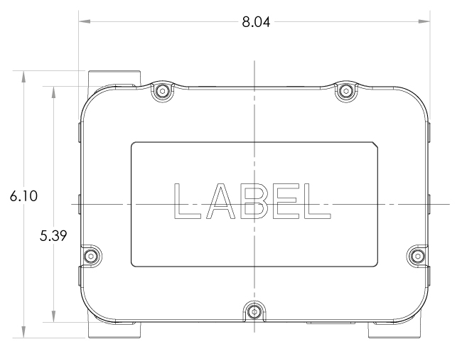
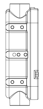
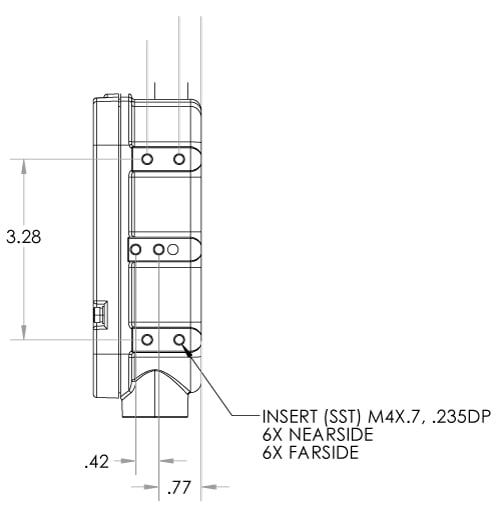
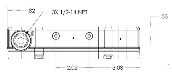
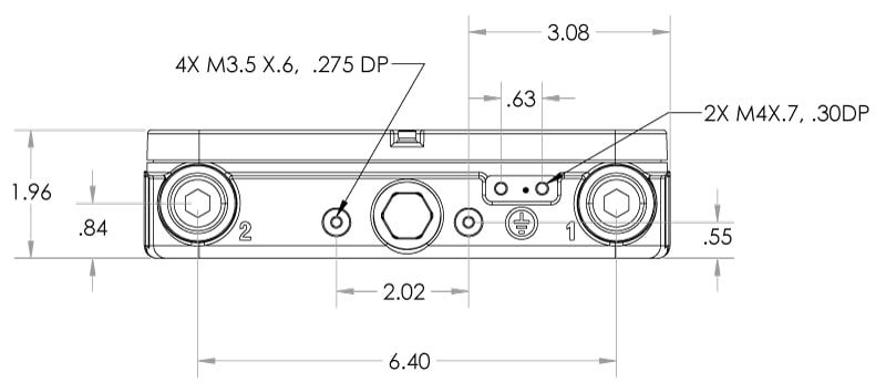
Mechanical Specifications
All measurements in the following figures are in inches.
Mounting Options
There are three mounting options for installing the Cisco IW-PWRADPT-MFITHZ= power supply unit.
-
Wall or Pole mount
-
Mount on the front of the Access Point: This option is applicable when using the AIR-ACCPMK3700= or AIR-ACCPMK3700-2= bracket.
-
Mount on the back of the Access Point: This option is applicable when using the AIR-ACCPMK3700-2= bracket.
Mount the PSU to a Wall or a Pole
Follow these steps to wall mount or pole mount the power supply unit (PSU) using screws or hose clamps.
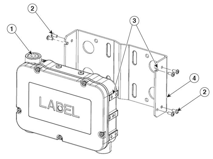
| 1 |
Power Supply |
3 |
Notch and screw location |
|
2 |
M4 Screws |
4 |
Mounting bracket |
Before you begin
|
Materials Needed |
Supplied in the Kit? |
Tightning Value |
|---|---|---|
|
Mounting bracket |
Yes |
— |
|
(8x) M4 Pan head screws |
Yes |
19-22 in-lbs |
|
(4x) M6 screws or ¼" bolts |
No |
— |
|
Two stainless steel band clamps (adjustable 2 to 5 inch (51 to 127 mm) |
No Required for pole/mast mount only. |
— |
|
Screw driver |
No |
— |
Procedure
|
Step 1 |
Mount the provided bracket to a wall or pole.
|
|
Step 2 |
Align the PSU notches on each side with the bracket screw holes. Hand-tighten two M4 screws into the hands free holes. |
|
Step 3 |
Secure the PSU to the bracket by screwing in the remaining six screws. Tighten all screws to a torque of 19–22 in-lbs. |
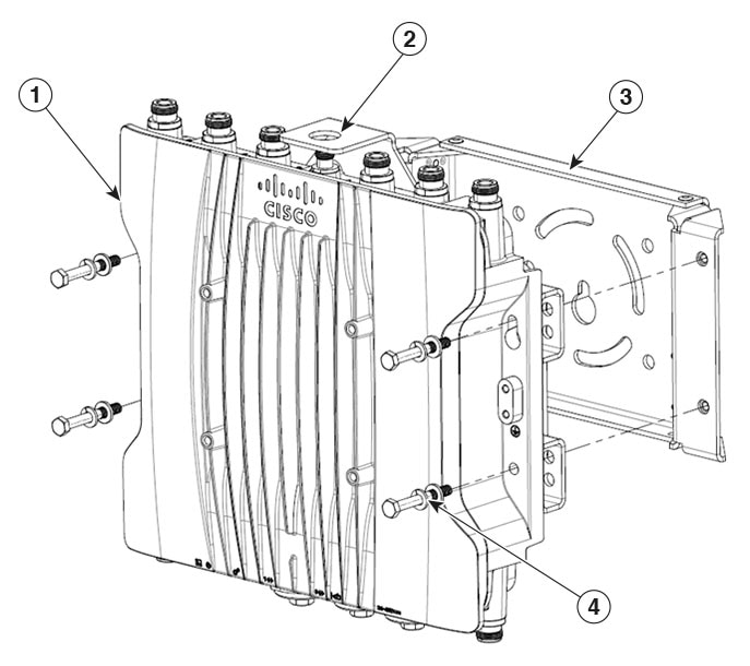
Mount the PSU on the Front of the Access Point
Follow these steps to mount the PSU on the front of the access point.
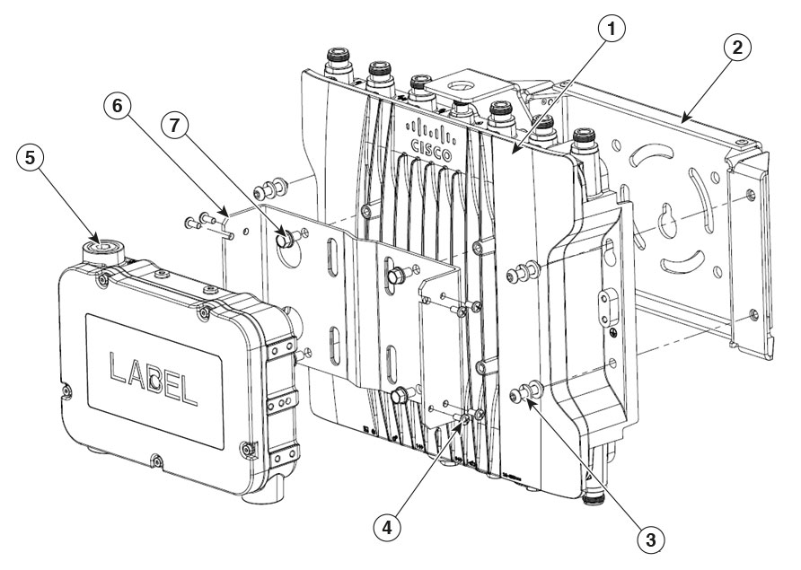
|
1 |
Access Point |
5 |
Power Supply Unit |
|
2 |
PSU mounting bracket |
6 |
AP mounting bracket (AIR-ACCPMK3700= or AIR-ACCPMK3700-2=) |
|
3 |
M6 binder head Split lock washer Flat washer |
7 |
1/4–20 Hex bolts |
|
4 |
M4 pan head screws |
Before you begin
 Note |
You may connect the AC and DC cables after mounting the assembled unit to the AP bracket. |
|
Materials Needed |
Supplied in the Kit? |
Tightning Value |
|---|---|---|
|
Mounting bracket |
Yes |
— |
|
(8x) M4 Pan head screws |
Yes |
19–22 in-lbs |
|
(4x) 1/4–20 Hex bolts |
Yes |
45–52 in-lbs |
|
(4x) M6 binder head with split lock and flat washer |
No |
45–52 in-lbs |
|
AIR-ACCPMK3700= or AIR-ACCPMK3700-2= bracket |
No |
— |
|
10mm or 3/8 socket |
No |
— |
|
Screw driver |
No |
— |
Procedure
|
Step 1 |
Mount the AP mounting bracket.
|
|
Step 2 |
Attach the AP to the AP mounting bracket using M6 binder head bolts. |
|
Step 3 |
Align and Install the PSU Mounting Bracket Align the PSU mounting bracket on the front of the access point and use 1/4-20 Hex bolts and tighten them with a torque of 45–52 in-lbs. |
|
Step 4 |
Secure the PSU to the Bracket Align the PSU notches on each side with the PSU bracket screw holes. Hand tighten two M4 screws into the hands free holes. |
|
Step 5 |
Screw the remaining six screws to secure the PSU to the bracket. Tighten all screws with a torque of 19–22 in-lbs. |
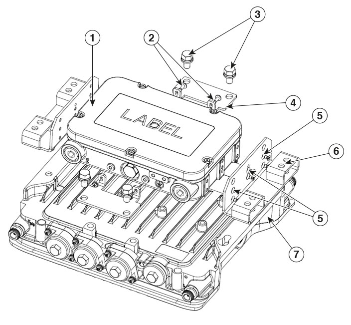
Mount the PSU on the Back of the Access Point
Follow these steps to mount the PSU on the back of the access point.
|
1 |
Power Supply Unit |
5 |
M4 Pan head screws |
|
2 |
M3.5 Pan head screws |
6 |
Adapter bracket |
|
3 |
M8 Hex bolts with Split and Flat washers |
7 |
Cisco AP |
|
4 |
Support bracket |
|
1 |
Cisco AP |
3 |
Mounting bracket |
|
2 |
TNC protection bracket |
4 |
M6 Hex head with Split and Flat washers |
Before you begin
Note |
You need to connect the AC and DC cables to the power supply unit before mounting the assembled unit to the AP bracket. |
|
Materials Needed |
Supplied in the Kit? |
Tightning Value |
|---|---|---|
|
(2x) Side adapter bracket |
Yes |
— |
|
(4x) M3.5 Pan head screws |
Yes |
14–17 in-lbs |
|
(4x) M8 Hex bolts |
Yes |
72–84 in-lbs |
|
(4x) Split washer |
Yes |
— |
|
(4x) Flar washer |
Yes |
— |
|
(2x) Support bracket |
Yes |
— |
|
(12x) M4 Pan head screws |
Yes |
19–22 in-lbs |
|
(4x) M6 Hex head with Split and Flat washers |
Yes |
45–52 in-lbs |
|
AIR-ACCPMK3700-2= bracket |
No |
— |
|
13-mm box-end wrench or socket set |
No |
— |
|
Screw driver |
No |
— |
Procedure
|
Step 1 |
Attach the side adapter brackets to the PSU using (12) M4 screws. Tighten the screws with 19–22 in-lbs torque. |
||
|
Step 2 |
Attach the support brackets to the PSU. Hand tighten the four M3.5 screws. |
||
|
Step 3 |
Remove the two M8 bolts from the AP's TNC protection bracket.
|
||
|
Step 4 |
Attach the PSU assembly to the AP using four M8 bolts. Tighten the M8 bolts with 72–84 in-lbs of torque. |
||
|
Step 5 |
Tighten the M3.5 screws on the support bracket. Use 14–17 in-lbs torque to tighten all the screws. |
||
|
Step 6 |
Mount the AP mounting bracket to a wall or pole.
|
||
|
Step 7 |
Mount the Cisco AP and the PSU assembly to the AP mounting bracket using the four M6 Hex bolts. Tighten the M6 bolts with 45–52 in-lbs of torque. |
Assembling the PSU for Installation
The IW-PWRADPT-MFITHZ== PSU requires assembling, which includes connecting the AC and DC cables to the unit. Follow these steps to prepare the PSU for powering the device:
-
Open the case.
-
Connect the AC cable.
-
Connect the DC cable(s).
-
Close the case.
Open the PSU Case
In this procedure, the PSU case is opened to connect the power cables to the power unit.
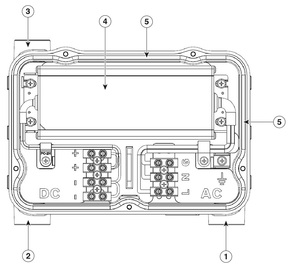
|
1 |
Port 1, AC cable |
4 |
PSU |
|
2 |
Port 2, DC cable |
5 |
Rubber O-Ring |
|
3 |
Port 3, DC cable (backup) |
Attention |
Do not touch or remove the rubber O-ring after opening the cover. Always ensure that the rubber O-ring is properly seated in its groove. This is crucial for achieving a proper seal and preventing water and dust from entering the case. |
Before you begin
|
Materials Needed |
Supplied in the Kit? |
|---|---|
|
2.5 mm Hex socket bit |
No |
|
3/8" Hex socket bit |
No |
|
LOCTITE-565 thread sealant |
No |
Procedure
|
Step 1 |
Remove the top cover of the case. Using a 2.5mm Hex socket, loosen the five screws securing the top cover to the case. |
||
|
Step 2 |
Remove the ½-14 NPT plugs as needed. |
||
|
Step 3 |
Access Ports for Cable Connections:
|
What to do next
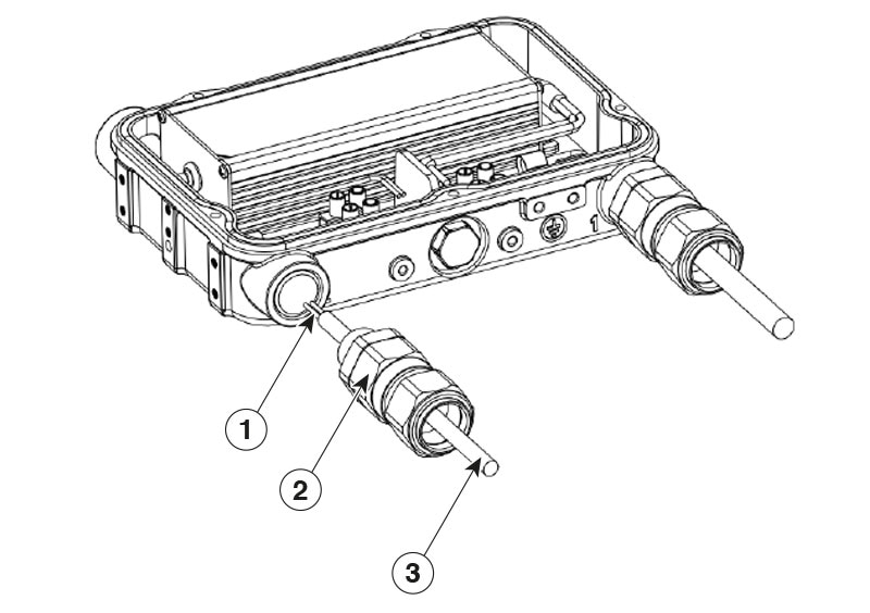
Connect the AC Power Cable
This procedure describes the steps to connect the input AC power cable to the PSU.
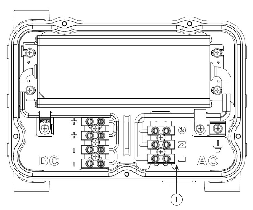
|
1 |
AC Terminal block and AC cable pins Molex 391002303, 12 mm pitch, 10-20 AWG
|
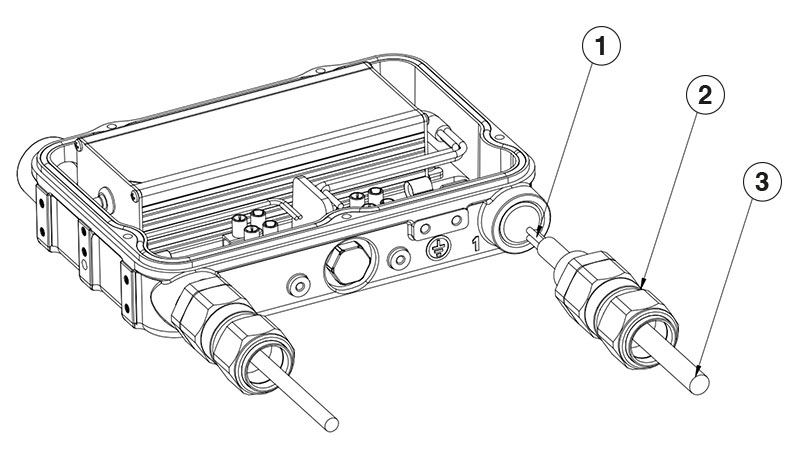
|
1 |
AC wires |
|
2 |
Gland Body or Conduit adapter |
|
3 |
AC cable (Armored cable, if required) |
Before you begin
|
Materials Needed |
Supplied in the Kit? |
||
|---|---|---|---|
|
AC power cable, 10-20 AWG, 3-core |
No |
||
|
½" NPT Cable gland or conduit adapter
|
No |
||
|
Screw driver |
No |
Procedure
|
Step 1 |
Insert the gland connector body or conduit adapter into Port 1 of the PSU. Apply thread sealant as required. |
||||||||
|
Step 2 |
Pass the power cable through gland connector or conduit adapter on Port 1. |
||||||||
|
Step 3 |
Connect the wires to appropriate pins. 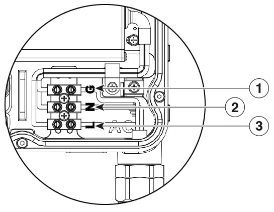
Secure the wires to the pins by tightening the screws to 7 in-lbs torque. |
||||||||
|
Step 4 |
Follow manufactures instructions to tighten the gland body or conduit adapter. Ensure a secure and watertight seal around the cable. |
Connect the DC Power Cable
This procedure describes the steps to connect the output DC power cable(s) to the PSU.
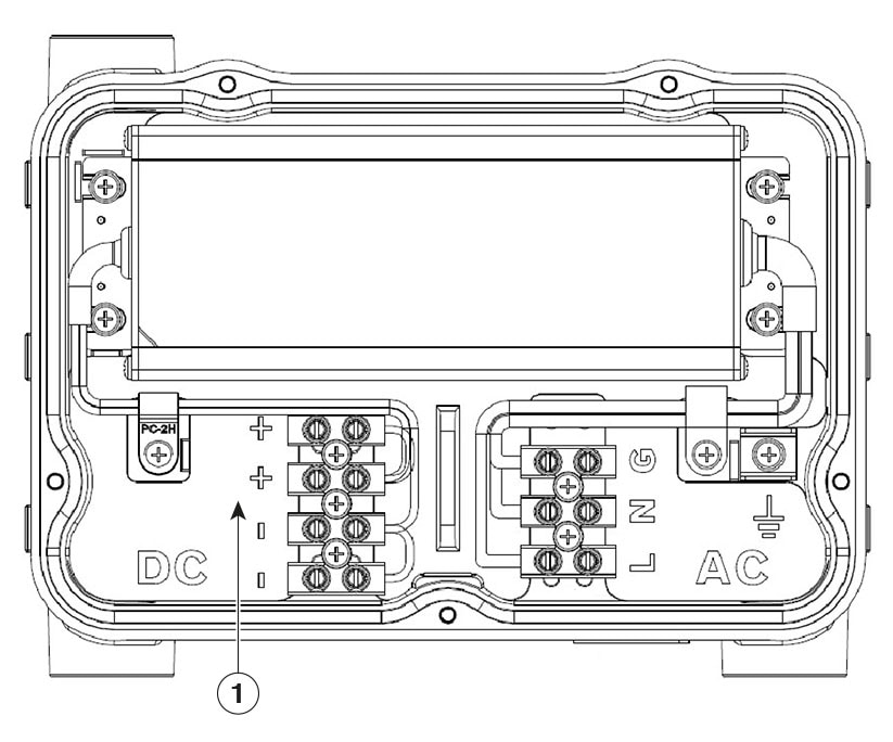
|
1 |
DC Terminal block and polarity pins Molex 391002304, 12 mm pitch, 10-20 AWG |
|
1 |
DC wires |
|
2 |
Gland Body or Conduit adapter |
|
3 |
DC cable (Armored cable, if required) |
Before you begin
|
Materials Needed |
Supplied in the Kit? |
||
|---|---|---|---|
|
DC power cable, 10-20 AWG, 2-core |
No |
||
|
½" NPT Cable gland or conduit adapter
|
No |
||
|
Screw driver |
No |
Procedure
|
Step 1 |
Thread the Gland Connector body or conduit adapter.
Apply thread sealant as required. |
||||||||||
|
Step 2 |
Pass the power cable through gland connector or conduit adapter.
|
||||||||||
|
Step 3 |
Connect the wires to appropriate pins.
Secure the wires to the pins by tightening the screws to 7 in-lbs torque. |
||||||||||
|
Step 4 |
Follow manufactures instructions to tighten the gland body or conduit adapter. Ensure a secure and watertight seal around the cable. |
Close the PSU Case
In this procedure, the PSU case is closed after all required cables are connected to the power unit.
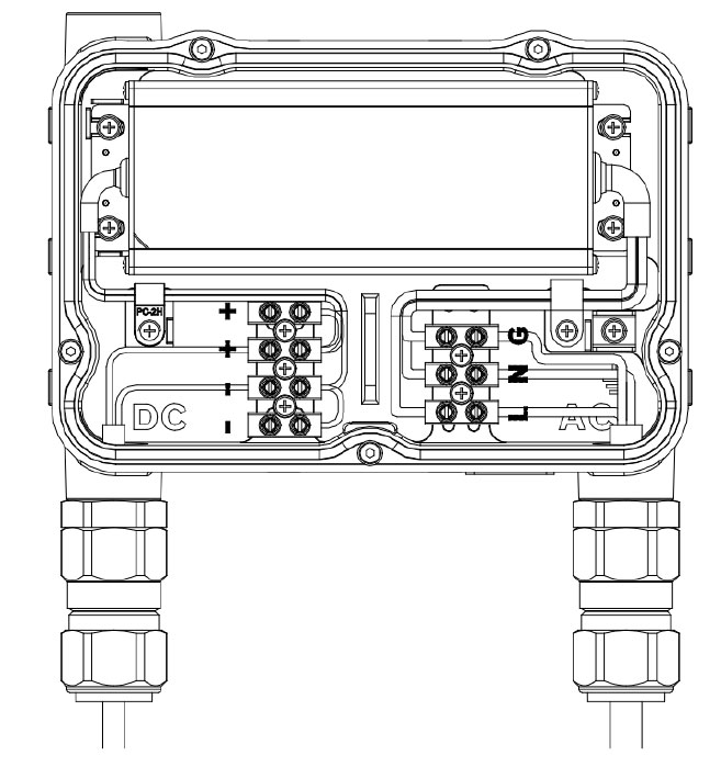
Attention |
Do not touch or remove the rubber O-ring. Always ensure that the rubber O-ring is properly seated in its groove. This is crucial for achieving a proper seal and preventing water and dust from entering the case. |
-
Install the top cover to the case.
Position the cover such that the five screw holes align with the case. Using a 2.5mm hex socket, apply 8 in-lbs of torque to tighten the five screws and secure the top cover to the case.
Ensure the O-ring is not pinched. If it is, reseat the O-ring in its groove and reinstall the cover as necessary.
Before you begin
|
Materials Needed |
Supplied in the Kit? |
|---|---|
|
2.5 mm Hex socket bit |
No |
Ground the PSU
This procedure describes the steps to ground the PSU.
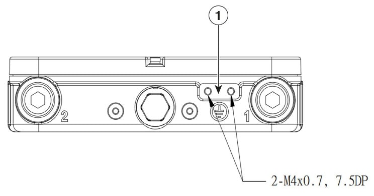
|
1 |
Grounding Point |
Before you begin
|
Materials Needed |
Supplied in the Kit? |
|---|---|
|
Grounding Lug |
Yes |
|
2x M4 x 6mm screws |
Yes |
|
6 AWG Ground wire |
No |
|
Crimping tool |
No |
|
Screwdriver |
No |
Procedure
|
Step 1 |
Crimp the ground wire. Use a crimping tool to crimp the ground lug to the 6 AWG grounding wire |
|
Step 2 |
Connect the Ground Lug to the PSU case. Apply oxide inhibitor to both the ground lug and the PSU grounding point. Align the ground lug with the PSU grounding point
and using the two M4 screws, secure the ground lug to the grounding point. Tighten the screws using 20-25 in-lbs of torque.
|
Regulatory Information
The following information is for FCC compliance of Class B devices:
The equipment described in this manual generates and may radiate radio-frequency energy. If it is not installed in accordance with Cisco’s installation instructions, it may cause interference with radio and television reception. This equipment has been tested and found to comply with the limits for a Class B digital device in accordance with the specifications in part 15 of the FCC rules. These specifications are designed to provide reasonable protection against such interference in a residential installation. However, there is no guarantee that interference will not occur in a particular installation.
Modifying the equipment without Cisco’s written authorization may result in the equipment no longer complying with FCC requirements for Class A or Class B digital devices. In that event, your right to use the equipment may be limited by FCC regulations, and you may be required to correct any interference to radio or television communications at your own expense.
You can determine whether your equipment is causing interference by turning it off. If the interference stops, it was probably caused by the Cisco equipment or one of its peripheral devices. If the equipment causes interference to radio or television reception, try to correct the interference by using one or more of the following measures:
-
Turn the television or radio antenna until the interference stops.
-
Move the equipment to one side or the other of the television or radio.
-
Move the equipment farther away from the television or radio.
-
Plug the equipment into an outlet that is on a different circuit from the television or radio. (That is, make certain the equipment and the television or radio are on circuits controlled by different circuit breakers or fuses.)
Modifications to this product not authorized by Cisco Systems, Inc. could void the FCC approval and negate your authority to operate the product.
Hazardous Locations Standards and Marking Strings
Specific Conditions of Use
-
Cable glands/Conduit shall be ATEX/IECEx certified to meet IP66//67 ratings. The service temperature of the entry for the Cable glands/Conduit is 80.2°C (176.36°F).
-
In order to prevent an electrostatic discharge within a hazardous location, only touch with an insulating object or use means to continuously drain off electrostatic charges in the installation.
-
The equipment shall only be used in an area of at least pollution degree 2, as defined in IEC 60664-1.
Note
Provision shall be made to provide that the circuits are limited to overvoltage category II as defined in IEC 60664-1.
-
Transient protection shall be provided that is set at a level not exceeding 140 % of the peak rated voltage value at the supply terminals to the equipment”.
|
The following hazardous locations marking strings are provided on IW-PWRADPT-MFITHZ= models |
|---|
|
CSA 24CA80212567U |
|
Class I, Division 2, Groups A, B, C, and D |
|
Ex ec IIC Gc Ex tc IIIC Dc |
|
Class I, Zone 2, AEx ec IIC Gc |
|
Zone 22 AEx tc III C Dc |
|
CSANe 25ATEX1046U |
|
IECEX CSA 25.0030U |
|
Ex ec IIC Gc Ex tc IIIC Dc |
|
|
|
|
 Feedback