Introduction
This document introduces the new configuration model for the Cisco Catalyst 9800 Wireless Controller and provides general guidelines for its deployment. The purpose of this document is to:
-
Provide an overview of the configuration model
-
Highlight key use cases and deployments
-
Provide details on best practices, monitoring and migration
Feature Overview
Introduction to the Best-Practice driven configuration model
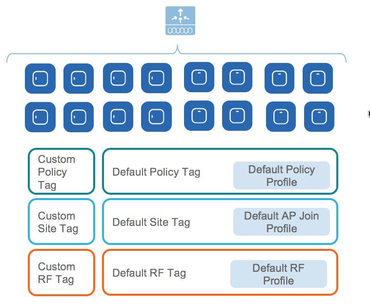
Cisco Catalyst 9800 Wireless Controller configuration data model is based on design principles of reusability, simplified provisioning, enhanced flexibility and modularization to help manage networks as they scale and simplify management of dynamically changing business and IT requirements.
This model provides a model for the client/AP devices to derive their configurations from profiles which are contained within Tags. AP can be mapped to the tags either statically or as part of the rule engine that runs on the controller and comes into effect during the AP join process. Configuration objects are modularized as objects which helps in reusability of configuration. In addition, a flat tag-based configuration model eliminates the complexities associated with inheritance and container-based grouping leading to a simpler and more flexible configuration that can ease change management.
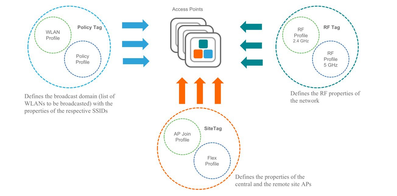
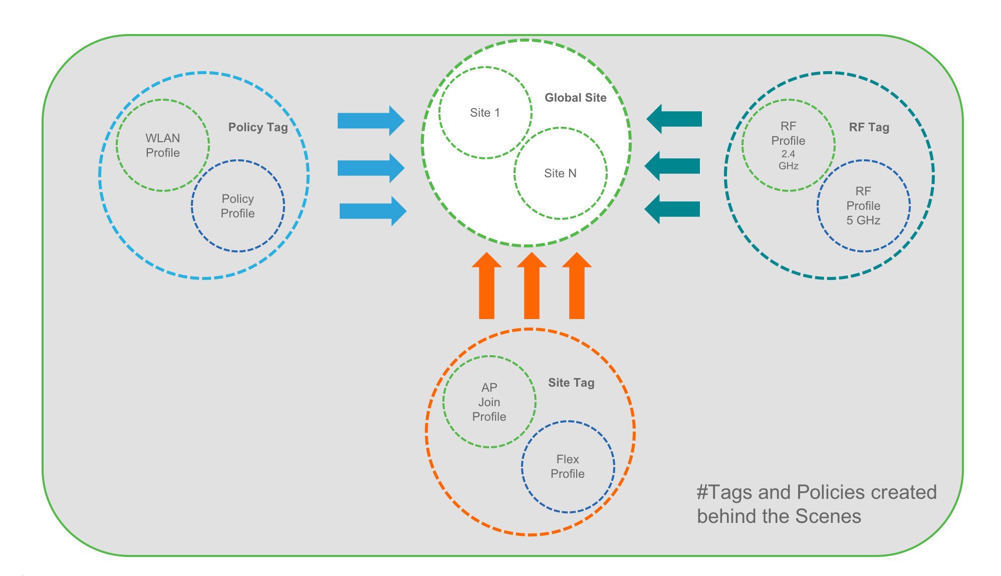
Elements of the configuration model–Tags and Profiles
Profiles
Profiles define the properties of the AP or associated clients. Profiles are reusable entities which can be used across tags. Default Policy profile, AP Join profile, Flex profile and 2.4/5GHz RF profiles are available by default on the wireless controller at boot time.
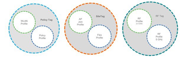
There are different kinds of profiles depending on the characteristic of the network they define. These profiles are in turn part of a larger construct called a Tag, as defined in the previous section.
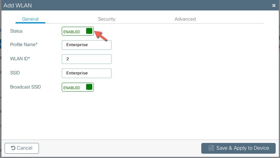
WLAN Profile
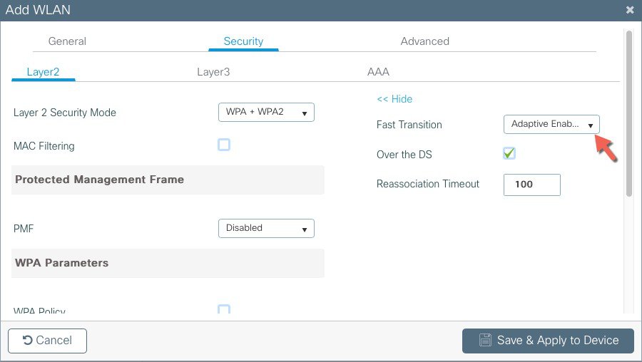
WLAN profile defines the properties of a WLAN such as Profile Name, Status, WLAN ID, L2 and L3 Security parameters, AAA Server associated with this SSID and other parameters that are specific to a particular WLAN.
Policy Profile
Policy Profile
The policy profile defines the network policies and the switching policies for a client with the exception of QoS which constitute the AP policies as well. Policy profile is a reusable entity across tags. Anything that is a policy for the client applied on the AP/controller is moved to the policy profile. For example, VLAN, ACL, QOS, Session timeout, Idle timeout, AVC profile, Bonjour profile, Local profiling, Device classification etc. The switching policies define central switching or local switching attribute of a WLAN.
The WLAN Profile and Policy Profile are both part a Policy Tag and define the characteristics and policy definitions of a set of WLANs.

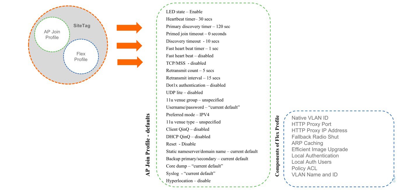
AP Join Profile
Following parameters will be part of the AP join profile – CAPWAP IPV4/IPV6 , UDP Lite, High availability, Retransmit config parameters, global AP failover, Hyper location config parameters , Telnet/SSH, 11u parameters etc. For AP join profile changes, a small subset requires CAPWAP connection to be reset since these parameters pertain to the characteristic of the AP
Flex Profile
The flex profile contains the remote site-specific parameters. For example, the master and slave AP list, the EAP profiles which can be used for the case where AP acts as an authentication server, local radius server information, VLAN-ACL mapping etc.
The AP Join Profile and Flex Profile are both part a Site Tag and define the characteristics of a local or remote site.
 Note |
When a site tag contains a Flex Profile, APs tagged with this site tag will be converted to FlexConnect mode. No reboot is required when AP is moving from Local to FlexConnect mode but CAPWAP is reset. |
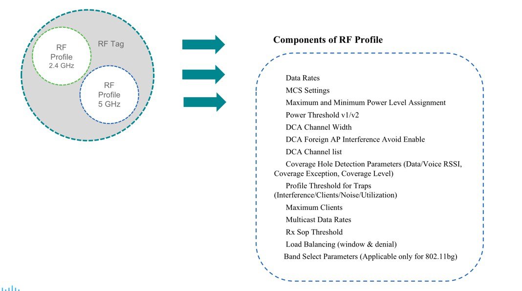
RF Profile
By default, there exists two default RF Profiles (one for 802.11a and one for 802.11b). RF profiles constitute the RF specific configurations such as Data rates, MCS settings, Power assignment, DCA parameters, CHDM variables and HDX features. One 802.11a RF profile and one 802.11b RF profile can be added to an RF Tag
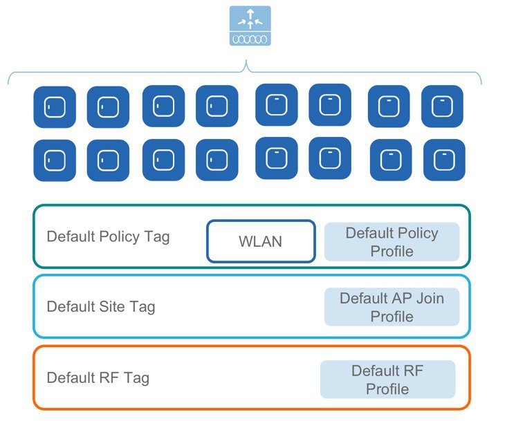
Tags
A Tag’s property is defined by the policies associated to it. This property is in turn inherited by an associated client/AP. There are various type of tags, each associated to different profiles. No two types of Tags include profiles having common properties. This helps eliminate the precedence amongst the configuration entities to a large extent. Every Tag has a default that is created when the system boots up.
There are three kinds of tags:
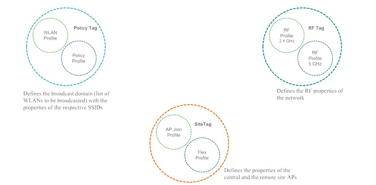
Policy Tag
Policy tag constitutes the mapping of WLAN Profiles to Policy profiles.
A default policy tag with WLAN Profiles with WLAN ID < 16 is mapped to a default policy profile.
Site Tag
Site tag constitutes of two profiles, the flex profile and the AP join profile. The site tag defines the properties of a site, both central as well as remote (FlexConnect) site. The attributes of a site that are common across central and remote site are part of the AP Join profile. The attributes that are specific to flex/remote site are part of the flex profile.
Default Site Tag constitutes of the default AP Join profile. The default AP join profile values will be same as that for the global AP parameters today plus few parameters from the AP group in today’s configuration like “preferred mode”, 802.11u parameters ,Location etc.
RF Tag
RF tag constitutes of the 2.4 and 5GHz RF profiles
Default RF Tag constitutes of the default 2.4GHz RF profile and the default 5GHz RF
Profile. The default 2.4 and 5GHz RF profiles contain default values for global RF profiles for the respective radios.
Association of tags to APs
Access Points are tagged based on broadcast domain, the site it belongs to and the RF characteristics desired. Once tagged, the AP gets a list of WLANs to be broadcasted along with the properties of the respective SSIDs, properties of the APs on the local/remote site and the RF properties of the network. By default, an AP is tagged with the default policy, site and RF tag unless explicitly changed. When a tag associated with an AP is changed, the AP resets its CAPWAP connection.
Day 0 Express Setup using WebUI
The Cisco Catalyst 9800 Wireless Controller provides a simplified first time out of box installation and configuration interface for all series of wireless controllers. This section provides a set of instructions to help easily setup the wireless controller to operate in a small, medium, or large network wireless environment, where access point(s) can join and together as a simple solution and provide various services, such as corporate employee or guest wireless access on the network.
Note |
The Express Setup can be used only for the first time in out of box installations or when controller configuration is reset to factory defaults. |
Configuring wireless controller
The general steps to configure the wireless controller are as follows:
Procedure
|
Step 1 |
Complete the configuration checklist. |
|
Step 2 |
Unpack, connect, and power on the wireless controller. |
|
Step 3 |
Connect a client machine to the front panel port or to the Service Port (after configuring Static IP or DHCP IP) of the wireless controller with an Ethernet cable. |
|
Step 4 |
Open a client web browser to access the wireless controller startup GUI. |
|
Step 5 |
Enter the settings from the completed configuration checklist. |
|
Step 6 |
Disconnect the wireless controller from client machine and connect to the network switch. |
|
Step 7 |
Connect access point(s) to the network switch. Access points join the wireless controller, and the configured wireless network become available. |
|
Step 8 |
Connect wireless client(s) to the available network. |
Configuration Checklist
The following checklist helps you to make the installation process easier, while using the GUI wizard to configure the wireless controller. While most of the information from the list is mandatory, there is some information that is optional (*). Take a moment to fill out:
-
Network switch requirement (see above reference for switch configuration example):
-
wireless controller switch port number assigned
-
wireless controller assigned switch port
-
Is the switch port configured as trunk?
-
Is there a management VLAN? Management VLAN ID
-
Is there a guest VLAN? Guest VLAN ID
-
-
Wireless controller Settings:
-
New admin account name
-
Admin account password
-
System name for the wireless controller
-
The current time zone
-
Is there an NTP server available? NTP server IP address
-
Wireless controller Management Interface:
-
IP address
-
Subnet mask
-
Default gateway
-
-
Management VLAN ID
-
-
Corporate Wireless Network
-
Corporate wireless name/SSID
-
Is a RADIUS server required?
-
Security authentication option to select:
-
WPA/WPA2 Personal
-
Corporate pass phrase (PSK)
-
WPA/WPA2 Enterprise)
-
RADIUS server IP address and shared secret
-
Is a DHCP server known? DHCP server IP address
-
-
Guest Wireless Network-optional
-
Guest wireless name/SSID
-
Is a password required for guest?
-
Guest pass phrase (PSK)
-
Guest VLAN id (use id)
-
Guest networking:
-
IP address
-
Subnet mask
-
Default gateway
-
-
Advanced option—Configure RF Parameters for Client Density as Low, Medium, or High.
Private and Public Cloud Bootstrap (Before Day 0)
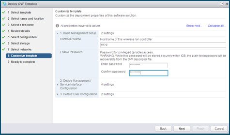
Private Cloud/VM
On ESXi when using vCenter to create the VM, there is a guided workflow to enter the VM bootstrap parameters
User can specify: login credentials, hostname and Management interface IP and remote management subnet
After VM boots up the user can directly connect to it using DAY 0 GUI or SSH, no other configuration needed
Note |
On KVM user needs to attach a config text file to the iso image, so it’s more manual. |
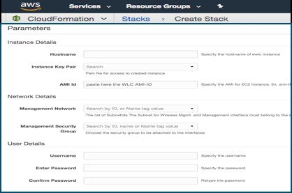
Public Cloud
On AWS Cloud using the provided CloudFormation Template the user has a guided flow to enter all the bootstrap info.
User can specify: login credentials, hostname and Management subnet.
After VM boots up the user can directly connect to it via DAY 0 GUI or SSH, no other configuration needed
Connecting C9800-40-K9 and C9800-80-K9 for Day 0
Procedure
|
Step 1 |
Connect a PC laptop's wired Ethernet port directly to Front Panel Port or to the Service Port IP (DHCP or Static) of the wireless controller ( see the following figure ). The port LEDs blink to indicate that both machines are properly connected. To connect via service port, connect the console, connect the uplink and service port to switch ports and then remotely login to set the hostname, user credential, IP and route on the device management interface. Once this is setup Day 0 on service port can be accessed by pointing the https browser session to the statically assigned IP. 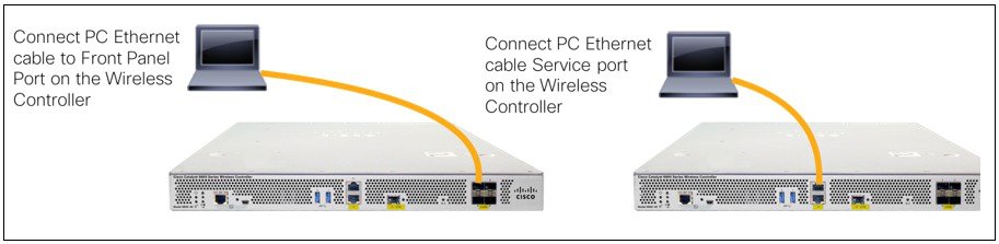
The LEDs on the front panel provide system status:
On the Catalyst 9800-L wireless controller, connect a PC laptop's wired Ethernet port directly to Front Panel Port or Service Port to access the Express Day 0 UI as shown below: 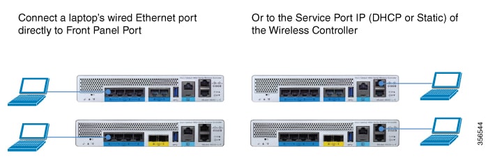 |
||
|
Step 2 |
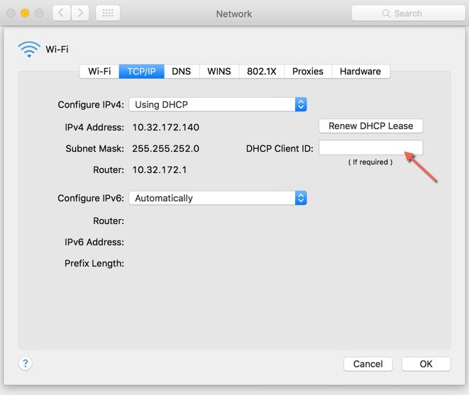
Configure DHCP option on the Laptop if connecting to the Front Panel port . This assigns an IP address to your Laptop (192.168.1.X) or you can assign a static IP address 192.168.1.X to your Laptop to access the wireless controller GUI; both options are supported. The following figure shows an example of the Mac Laptop getting an IP address from the front panel port for the initial configuration of the controller. 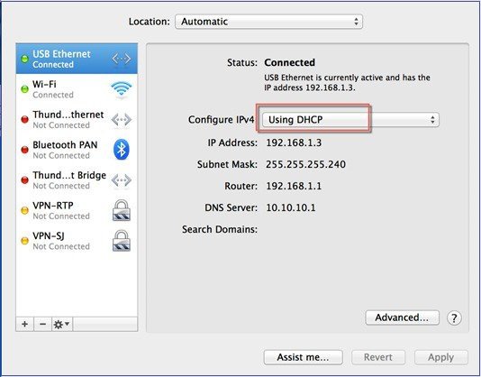 Show DHCP client-id needs to be populated when connecting via the front panel port.
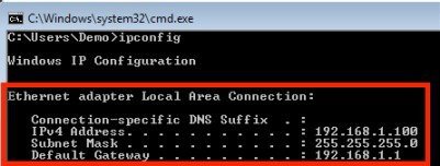
The following figure shows an example of network settings on Windows PC (Start > Run > CMD > ipconfig).
|
Accessing Day 0 Setup Workflow
Procedure
|
Step 1 |
Open a web browser (preferably Chrome and Safari) and open the URL: http://192.168.1.1. Enter credentials as “webui” for username and the serial number of your controller for the password. The following screen appears in your browser.
To create an admin account, do the following:
|
||
|
Step 2 |
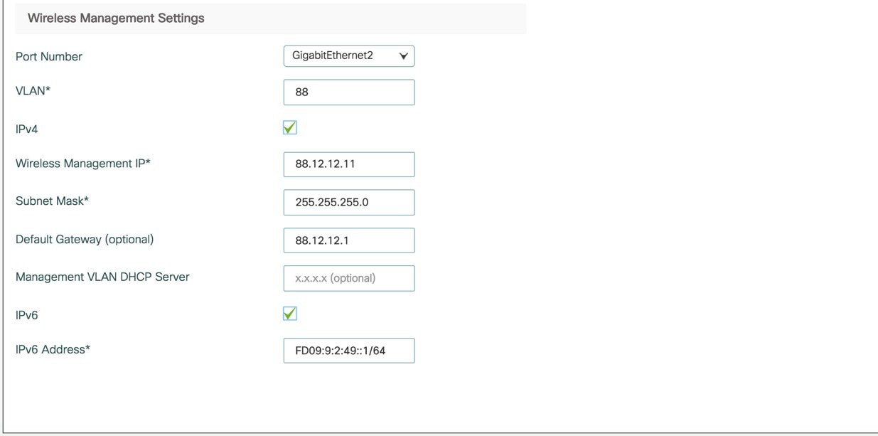
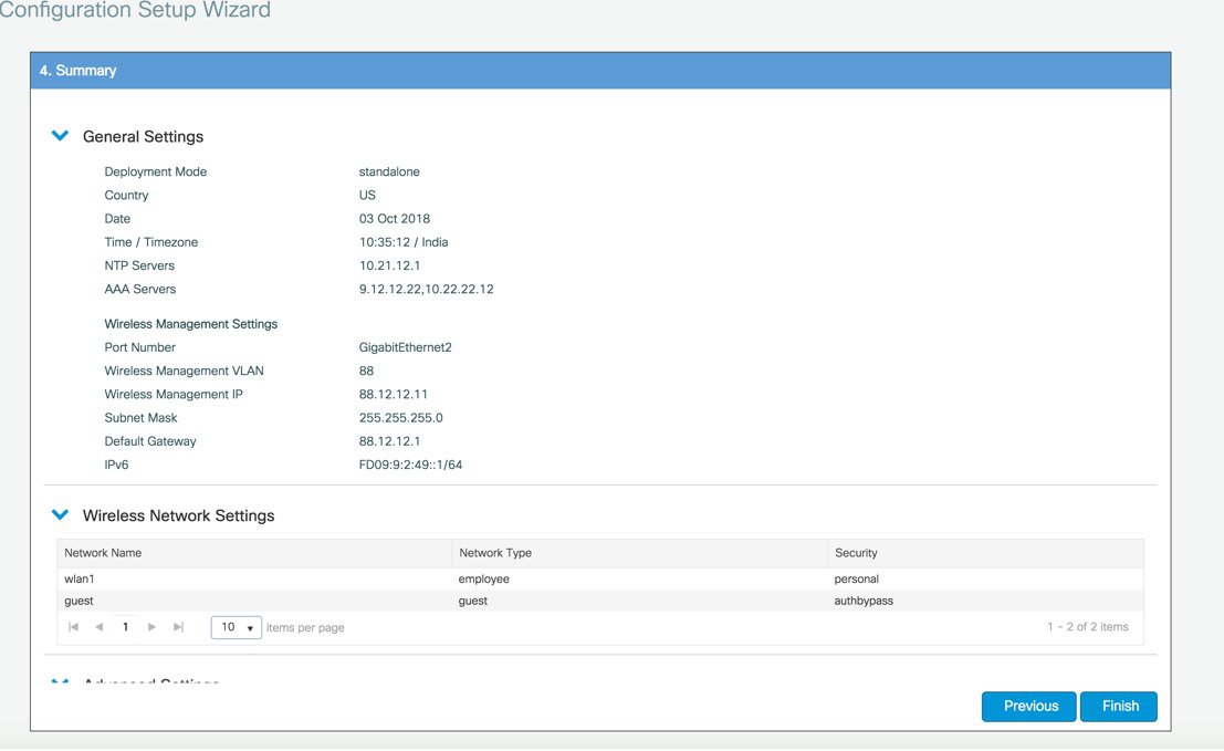
Log into the controller and in the General Settings screen, with the help of the checklist, fill in the following:
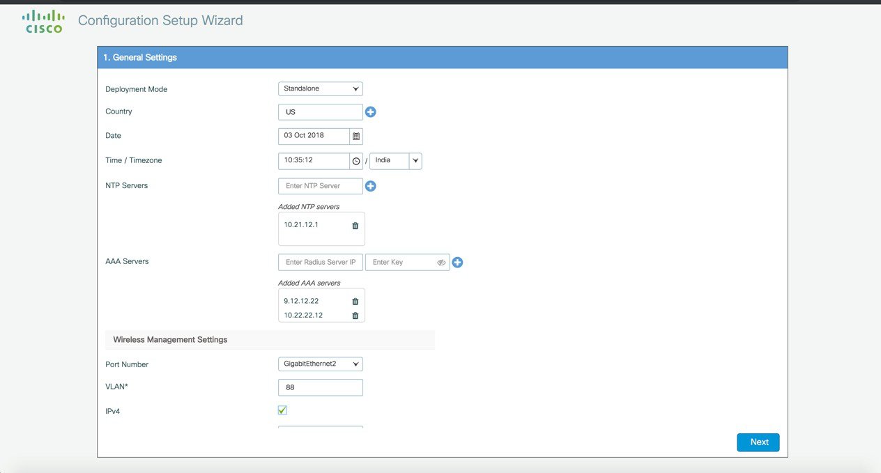
Three modes for Day 0 : Standalone, Active, Standby ( Active and Standby have options to setup HA SSO with local IP, remote IP and subnet mask configuration. 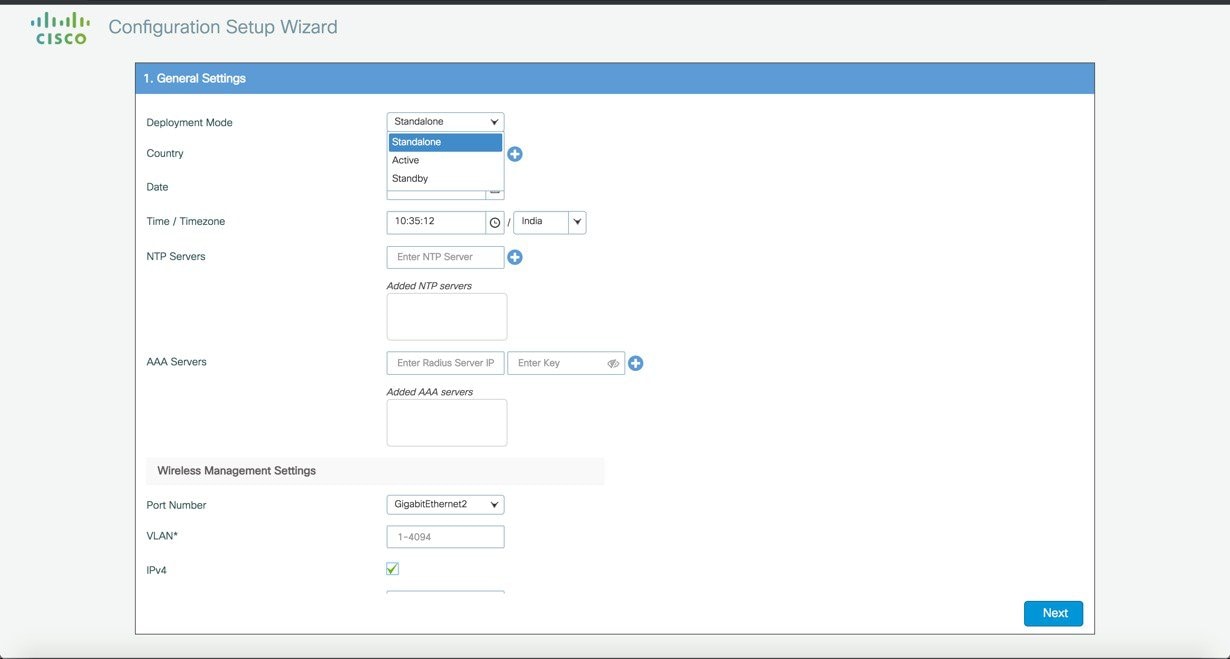 |
||
|
Step 3 |
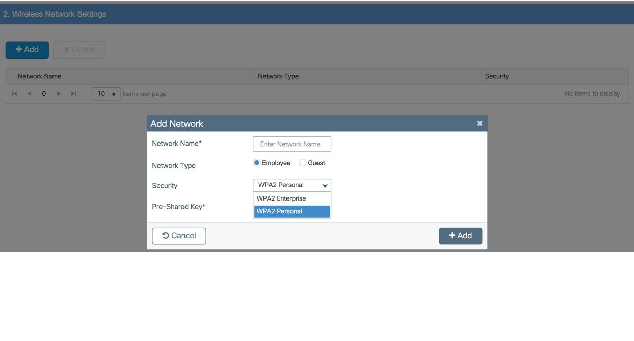
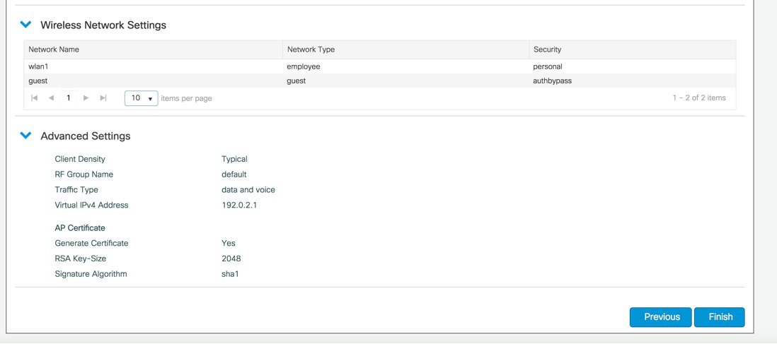
In the Wireless Networks Settings screen, in the Employee area, with the help of the checklist, fill in the following:
 |
||
|
Step 4 |
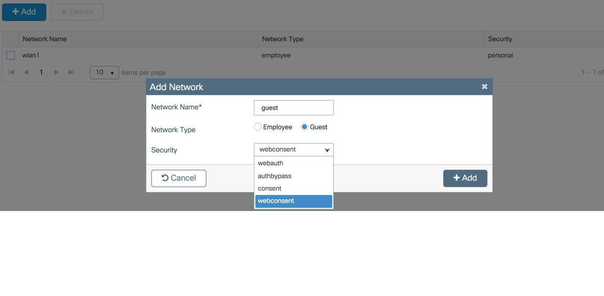
(Optional) In the Wireless Networks Settings screen, in the Guest area, with the help of the checklist, fill in the following
 |
||
|
Step 5 |
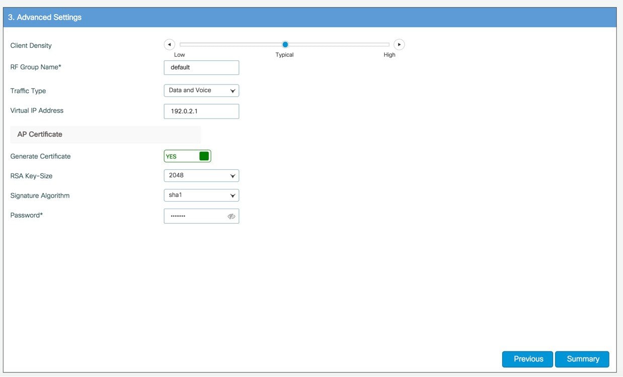
In the Advanced Settings screen, in the RF Parameter Optimization area, do the following: Select the client density as Low, Typical, or High. Configure the RF parameters for RF Traffic Type, such as Data and Voice. For VM and Cloud instances, AP Trustpoint certificate is generated by default as shown below.
The following CLIs depicts the default values when Low, Typical, or High Client density is selected: Typical-Client-Density-802.11aHigh-Client-Density-802.11a Low-Client-Density-802.11a Typical-Client-Density-802.11bg High-Client-Density-802.11bg Low-Client-Density-802.11bg |
||
|
Step 6 |
If all the settings are correct, click Finish.
 |
||
|
Step 7 |
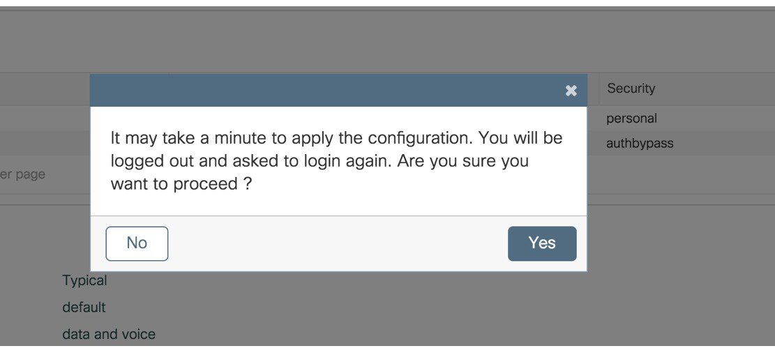
A message appears with a prompt It may take a minute to apply the configuration. You will be logged out and asked to login again. Are you sure you want to proceed?'
Click OK to apply final settings. The wireless controller logs out and the user needs to re-login to continue to the fully setup wireless controller. |
Wireless Basic Workflow
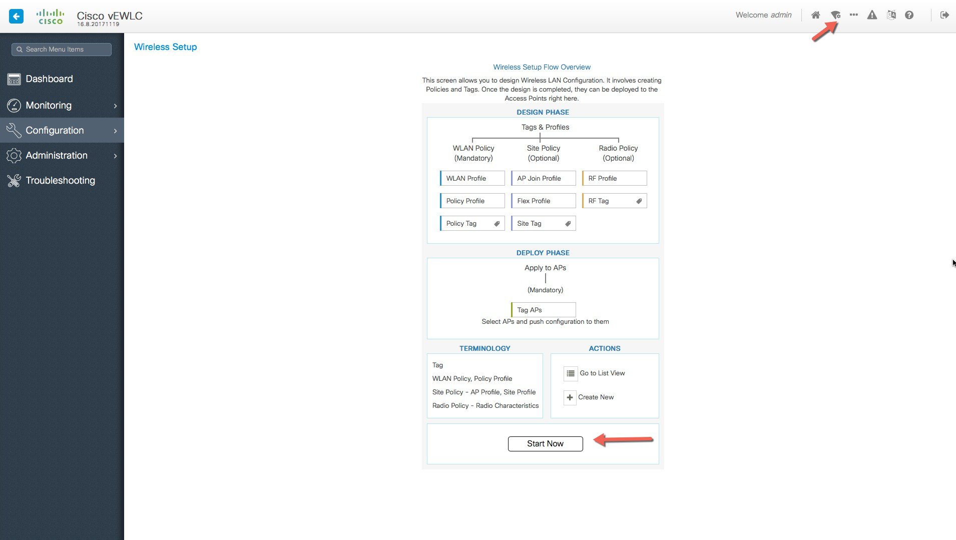
The wireless basic setup uses intent-based workflows to define local and remote sites, create wireless networks for these sites, define policies such as VLAN, ACL and QoS and also fine-tune RF characteristics. Corresponding policies and tags are created in the backend in accordance with the new configuration model but is transparent to the end-user. Access points are assigned to the site and in turn are assigned policy, RF and site tags.
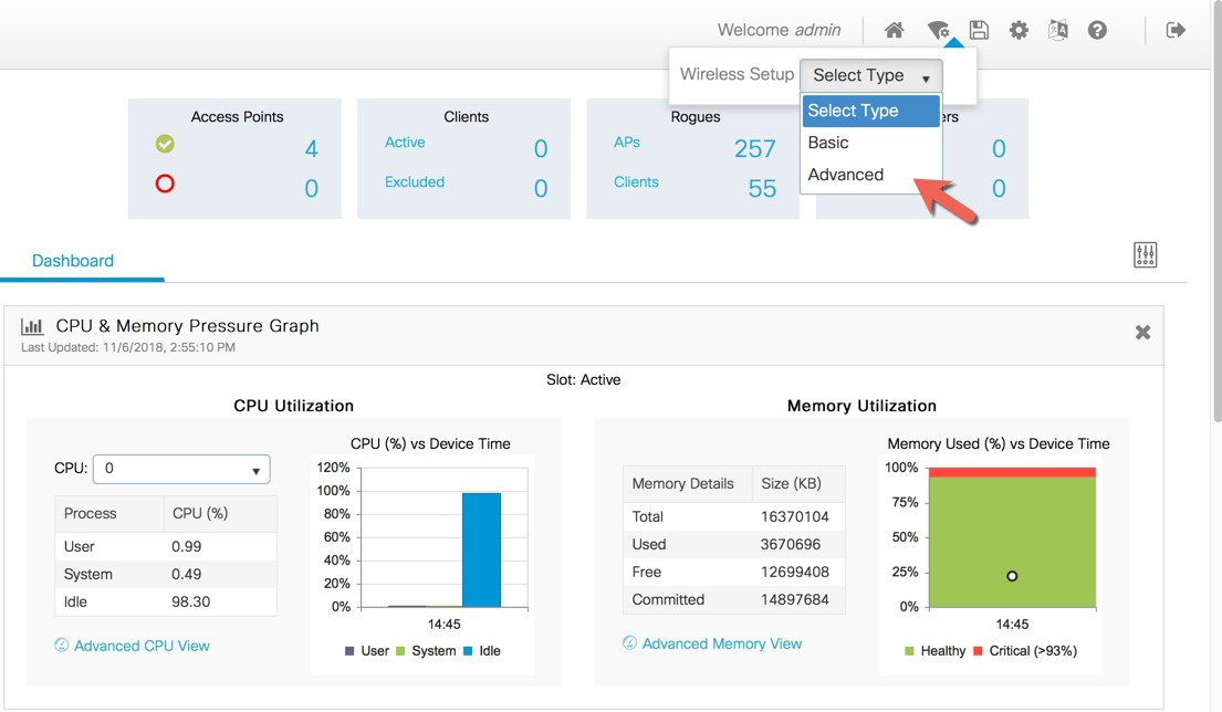
 In order to access the Basic Wireless Setup, click on the Wireless Setup Icon on the top-right hand corner of the dashboard
page and select ‘Basic’ as shown below:
In order to access the Basic Wireless Setup, click on the Wireless Setup Icon on the top-right hand corner of the dashboard
page and select ‘Basic’ as shown below:
Procedure
|
Step 1 |
Creation of new site and General Site Settings. A location is defined as a site either in the campus(local) 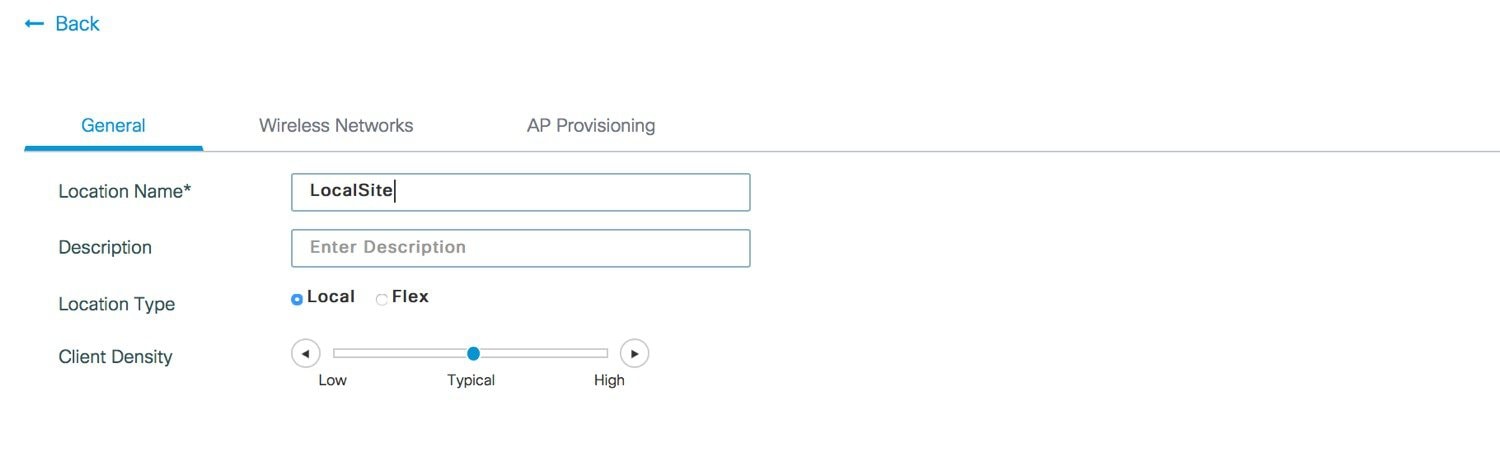 |
|
Step 2 |
Creation of Wireless Network and policies within the site . WLANs created as part of Day 0 setup are available to add to this site. These WLANs can be added as is or modified for the policy details that are required for this network in the local site. Alternatively, new SSIDs can be created using the Define new button. 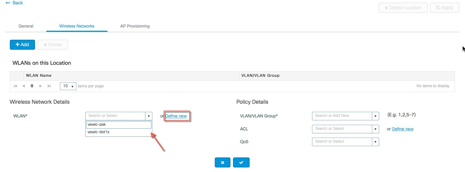 Creation of a Remote Site Similarly, a remote site can be created by selecting Location type as “Flex”. In addition to the field available on the local site, remote site specific parameters such as native VLAN ID and local AAA Servers can be configured on this page. Globally defined AAA server can be used or a new server can be added using the ‘Add New Server’ link.  On the Wireless networks tab, the SSID being added to the remote site can be configured as a local switching, local authentication SSID. 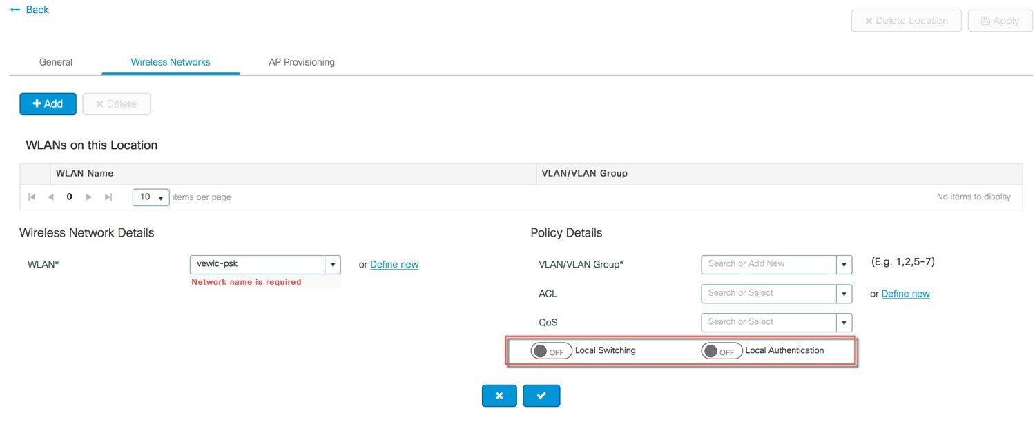 In the backend, a custom Site tag with a custom Flex profile is defined and associated with this remote site. 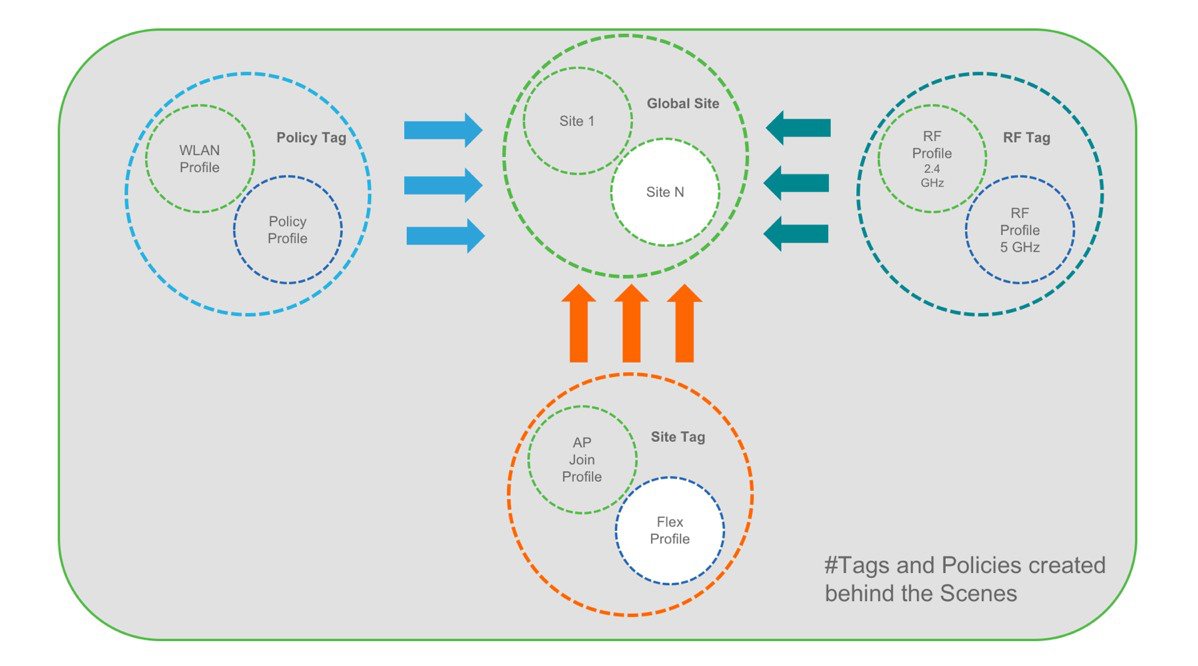 |
|
Step 3 |
Provisioning APs to Site. Once the Wireless network and RF characteristics are setup, Access points can be added to the local/remote site either using static AP MAC address assignment or by assigning already joined APs to a specific location. 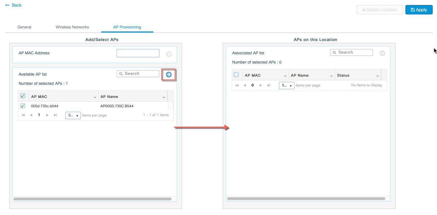 Policy, Site and RF tags are automatically pushed to the access points upon provisioning. 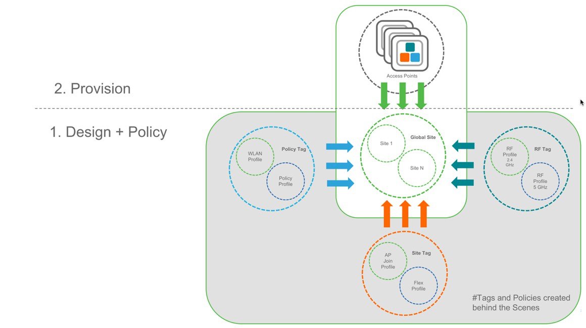 |
 or across the WAN in a branch (remote) that has a specific set of services, policies and RF. Select a Name, description and
Location type (Local or Flex) as well as client density as Low, Typical, or High. In the flow below, a local site is created
with the name LocalSite.
or across the WAN in a branch (remote) that has a specific set of services, policies and RF. Select a Name, description and
Location type (Local or Flex) as well as client density as Low, Typical, or High. In the flow below, a local site is created
with the name LocalSite.
Wireless Advanced Workflow
Guided workflow and Use cases
In order to access the Basic Wireless Setup, click on the Wireless Setup Icon on the top-right hand corner of the dashboard page and select ‘Basic’ as shown below.
A guided workflow has been created for easy navigation thru the steps required to setup the network using Cisco Catalyst 9800 Wireless Controller.
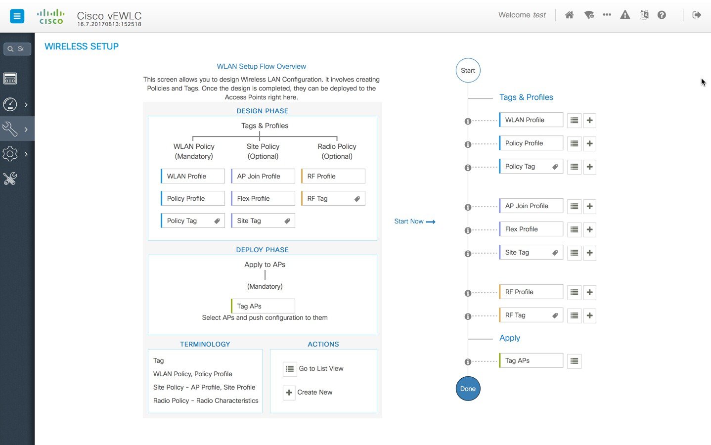
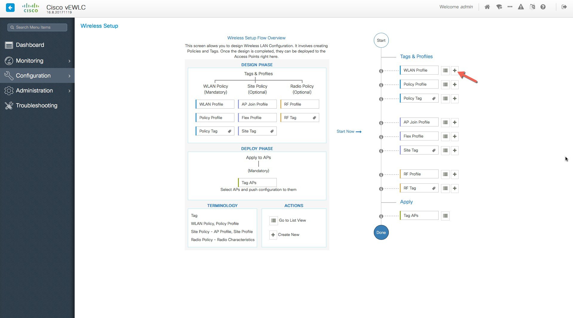
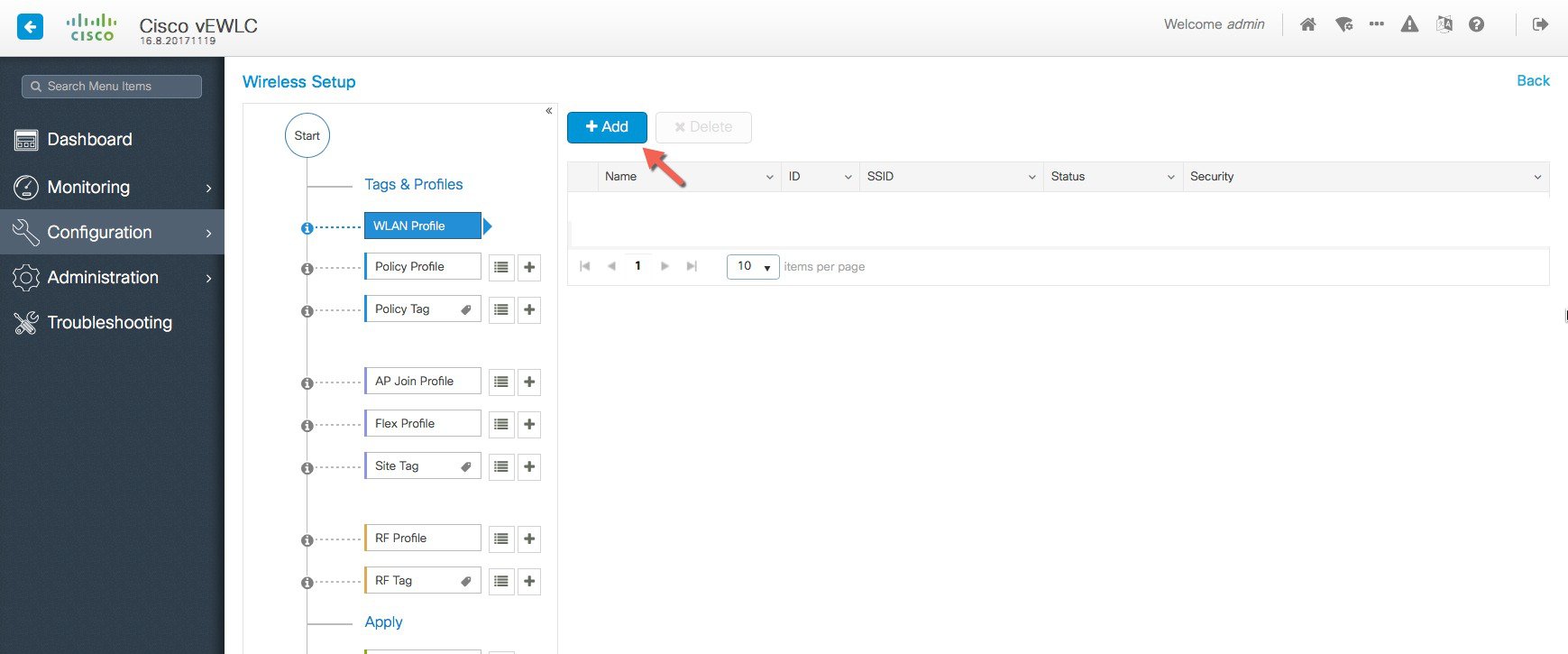
The following set of steps defines the logical order of configuration. Note that apart from the WLAN profile, all profiles and tags have a default object associated with it.
-
Creation of profiles
-
Create the required WLAN profiles (SSIDs)
-
Create the RF profiles(if non-default)
-
Create the Site profile (if non-default)
-
-
Creation of Tags
-
Create the Policy tag(if non-default)and map the SSIDs above to the policy profiles as required
-
Create the RF Tag (if non-default) and add the RF profiles for 11a and 11b to it
-
Create the Site tag(if non-default) and add the Flex profile ( if remote site) and the AP join profile(most cases will be default)
-
-
Associate the Tags to APs
If no custom tags are needed, this step is not required as default tags are associated with the APs
If the tag to be associated is non-default, associate the tags to the APs
-
Associate RF Tag to the AP/set of APs
-
Associate Policy Tag to the AP/set of APs
-
Associate Site Tag to the AP/ set of APs
-
Note |
It is not recommended to mix and match basic with advanced workflow. When using the basic setup workflow for creating local and remote sites, corresponding policies and tags are created in the backend in accordance with the new configuration model. The tags and policies, thus, created shouldn't be modified using the advanced workflow. |
Use Case 1 - Global SSIDs across the campus (802.1x, IOT PSK, Guest)
This is a simple use-case where an enterprise has the requirement of setting up an 802.1x, IOT or Guest SSID across the campus such that it is broadcasted on all access points across the deployment. The same policies and RF characteristics are applicable to all APs that are part of this global site. This section explains how that can be achieved using the Advanced Wireless Setup workflow.
Central site–Default config with minimal changes
Procedure
|
Step 1 |
Create SSIDs [WLAN ID between 1-16]
 Verify that a WLAN profile is created as follows. 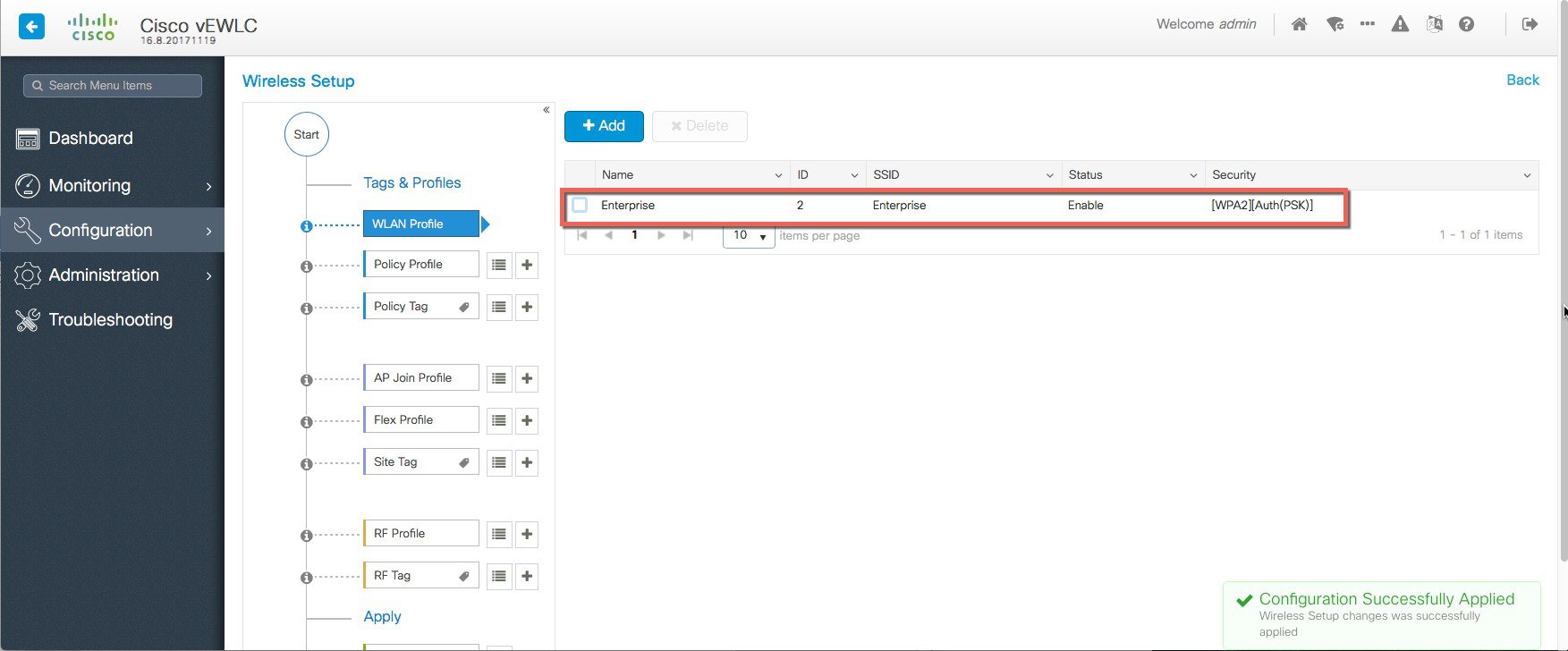 |
|
Step 2 |
A Default Policy Profile and Default Policy Tag are pre-configured so no specific policy configuration is required. 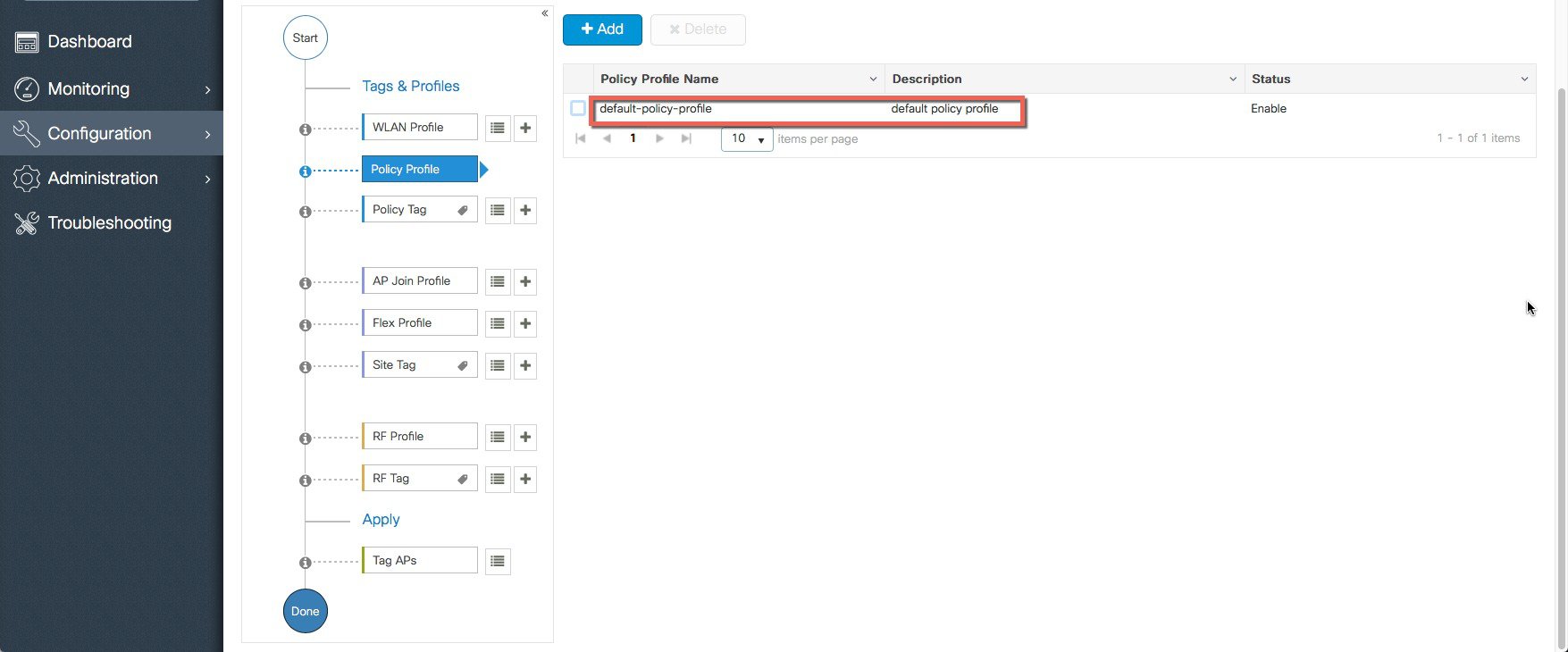 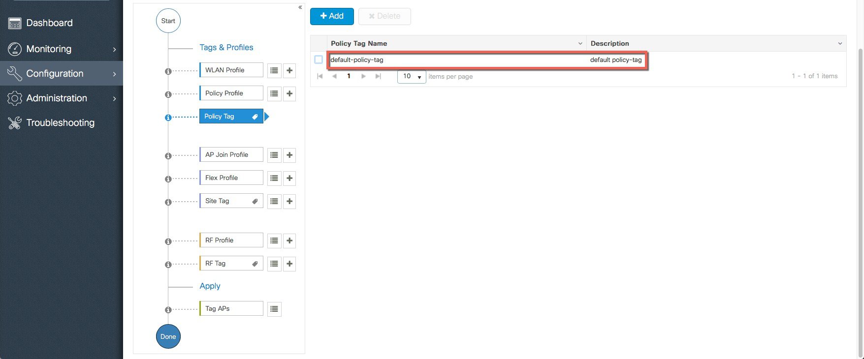 The SSID created in the first step is automatically added to this Default Policy Tag as shown below. 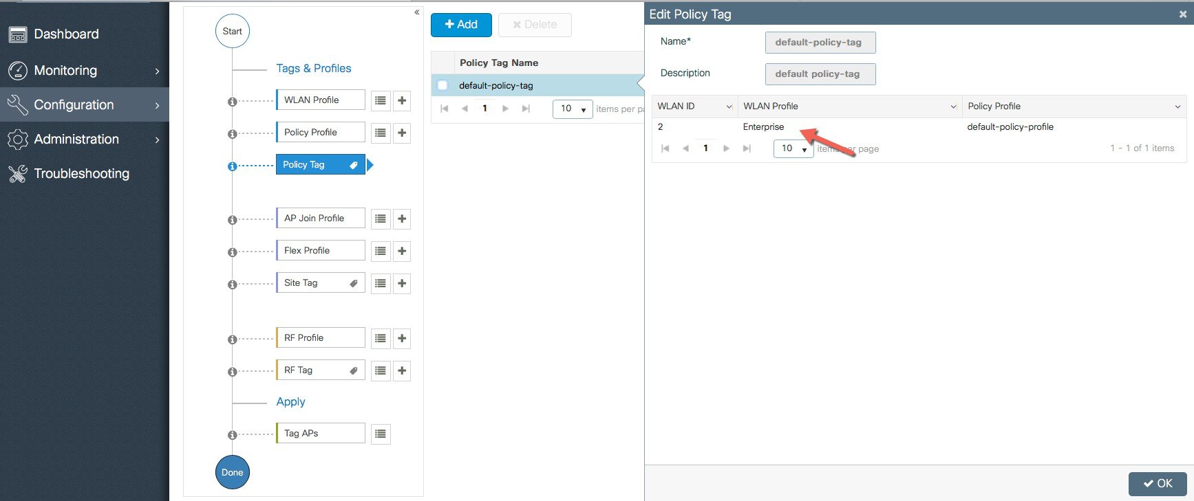 |
|
Step 3 |
A Default AP Join Profile and Site Tag is pre-configured so no specific site configuration is required. 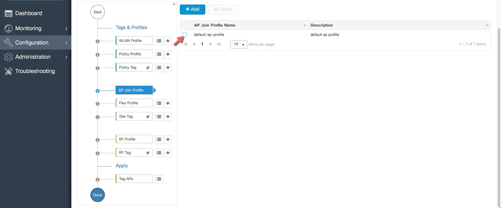  |
|
Step 4 |
A Default RF Profiles and RF Tag is pre-configured so no RF configuration is required. 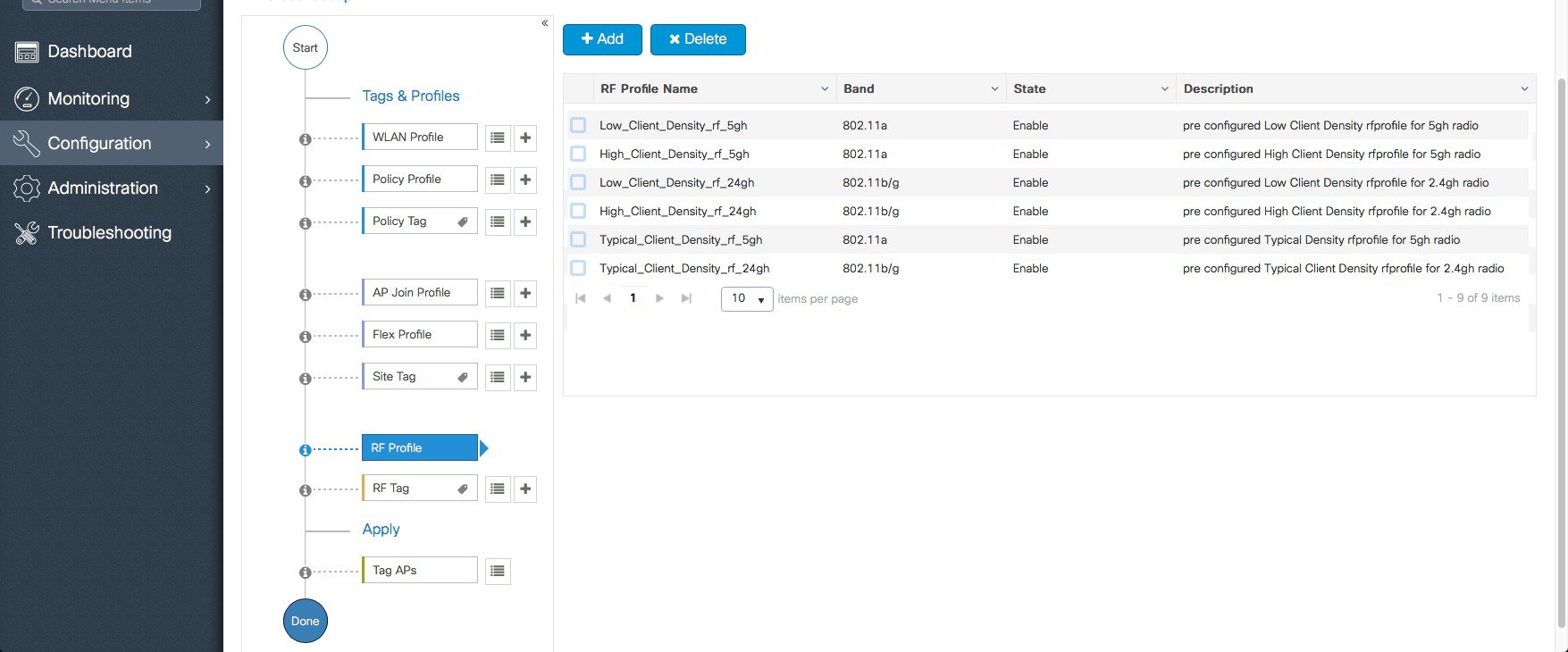 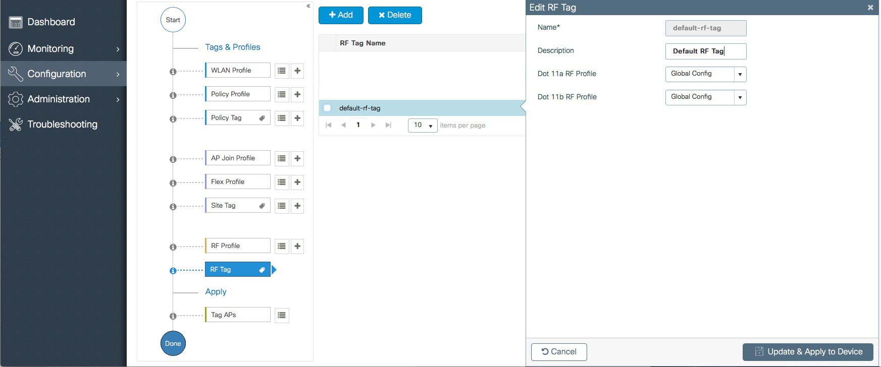 |
|
Step 5 |
APs are tagged with the default tags automatically so no explicit tagging is needed and the SSIDs will start broadcasting automatically across the campus. |
Use Case 2 – Local sites within a Campus
This use-case adds a local site to the campus deployment with custom SSIDs, Policies and RF characteristics. For example, a building in an enterprise campus that has the requirement to broadcast a custom SSID with a custom policy and has RF characteristics that are specific to a given site.
Procedure
|
Step 1 |
Create a custom Site Tag to tags APs belonging to this local site. 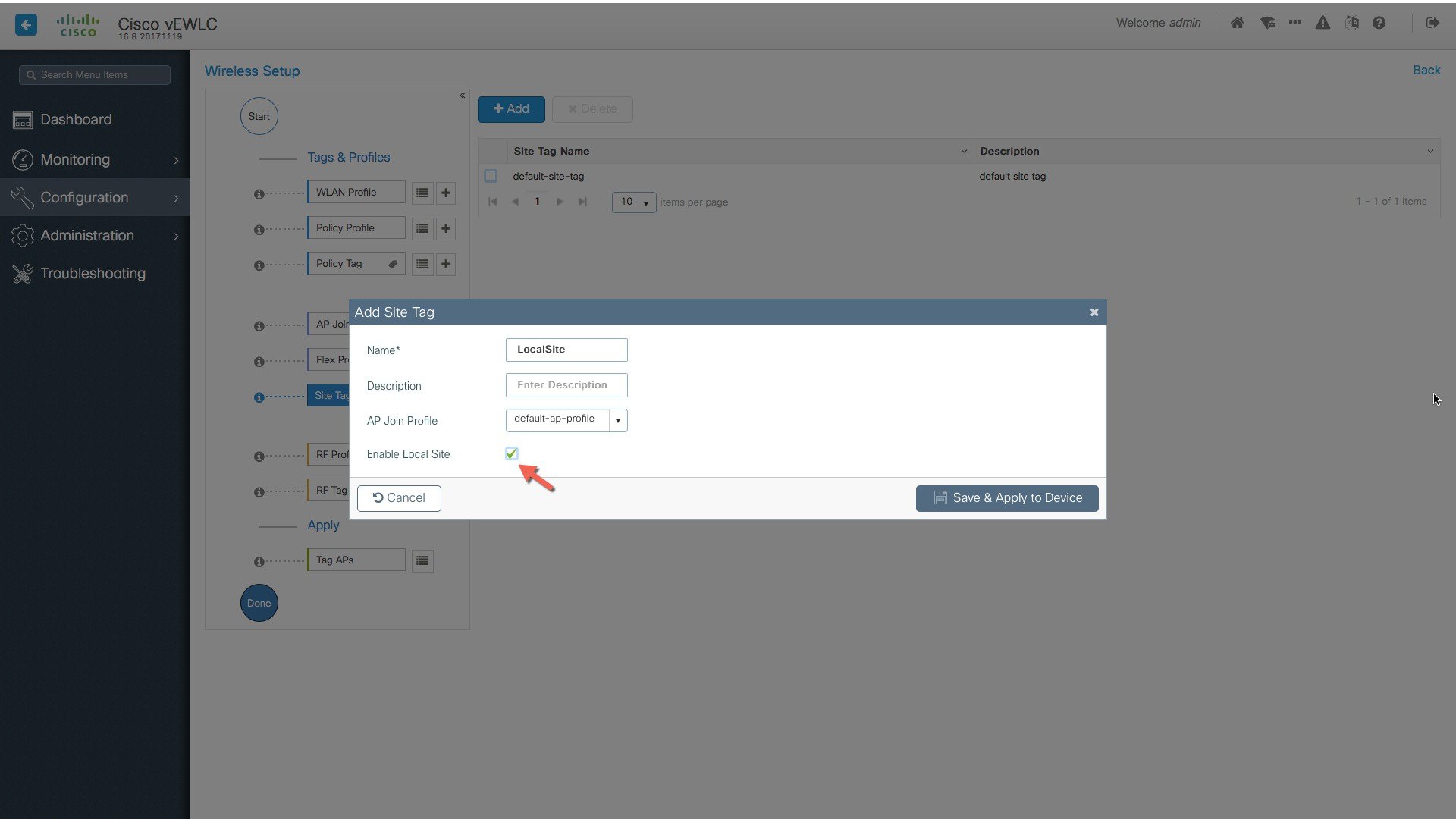 |
|
Step 2 |
Creation of site-specific SSIDs and Policies for the Local site. 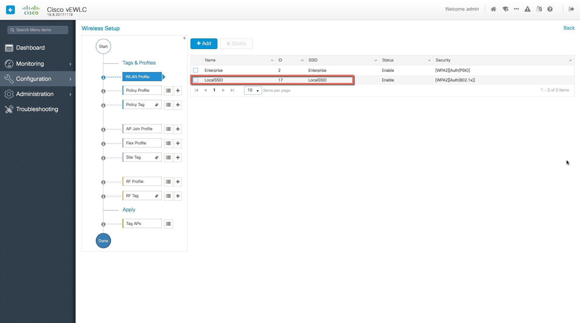 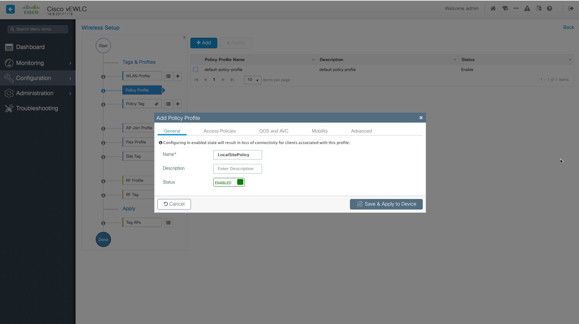 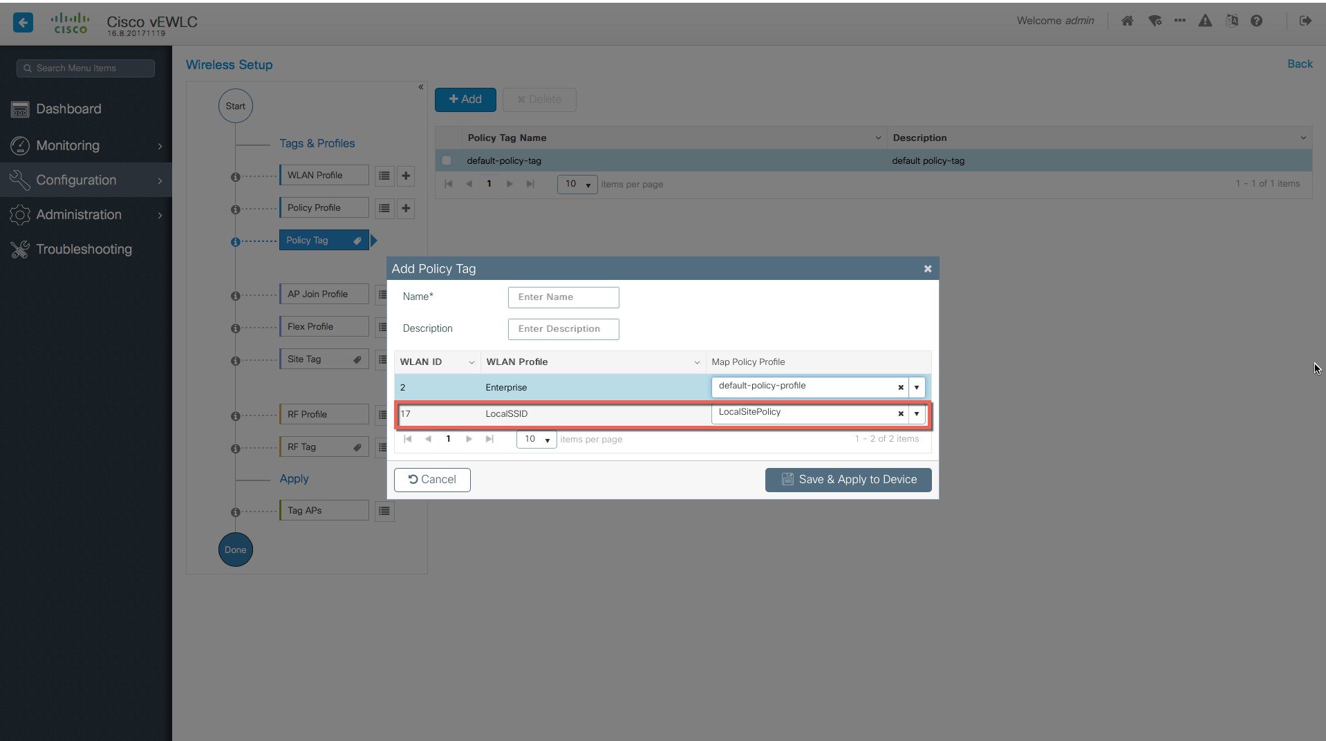 |
|
Step 3 |
Creation of specific RF profile and tag for the local site . 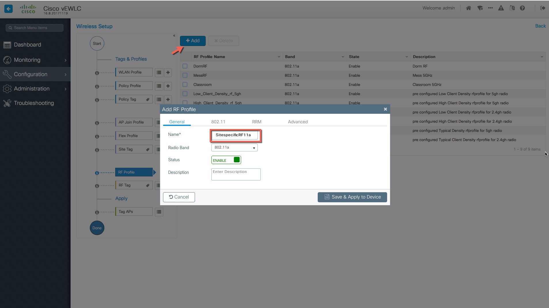 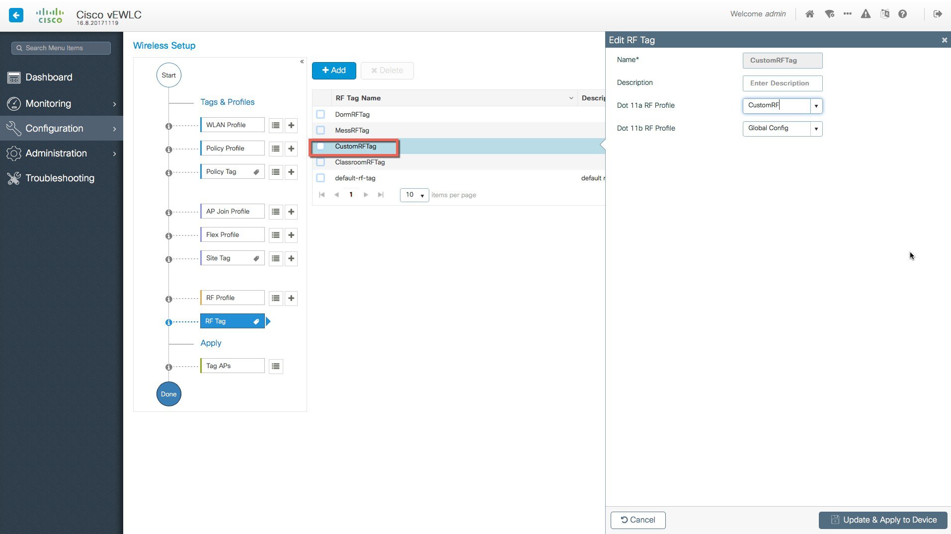 |
Use Case 3–Remote sites across the WAN
Procedure
|
Step 1 |
Creation of Remote sites with site-specific SSIDs and RF. 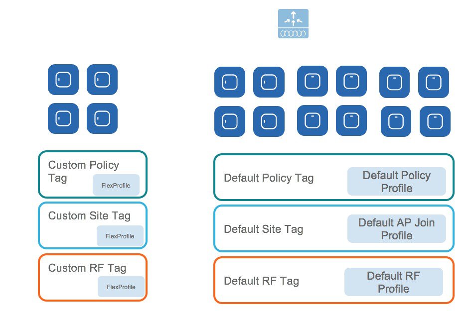 A remote site can be added by simply creating another site Tag and unchecking the box “Local Site” to add a Flex Profile. An existing site can also be converted to a remote site with this simple action.  |
|
Step 2 |
The APs in the remote site now need to be Tagged with the RemoteSite Tag and with the Policy and RF Tag, if non-default configuration is required. Once tagged with the remote site TAG, the AP s will be converted to FlexConnect mode dynamically. Tagging APs with Tags: 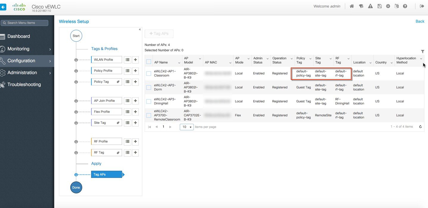 Specific/custom Policy, site and RF Tags can be added to APs as shown below. 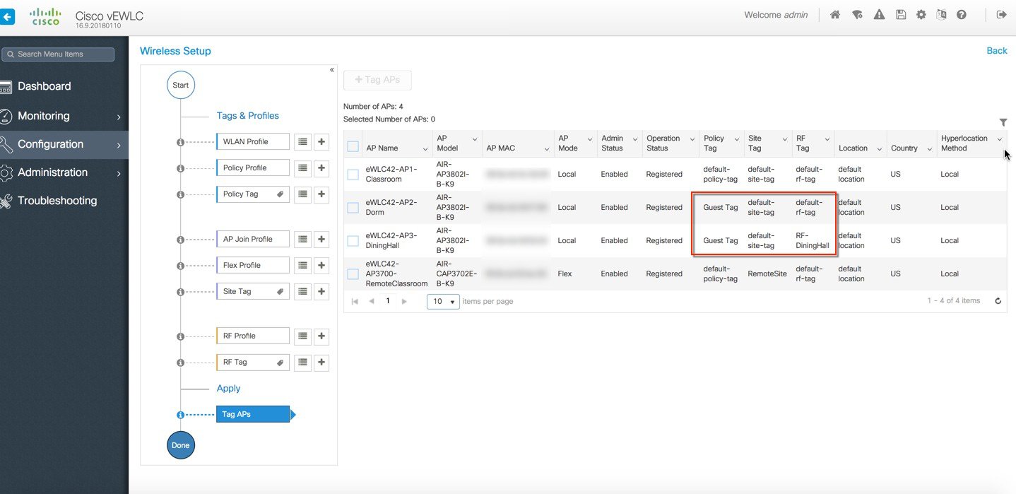 In the example below a custom Policy tag for Guest SSID and a custom RF Tag is being added to an AP. 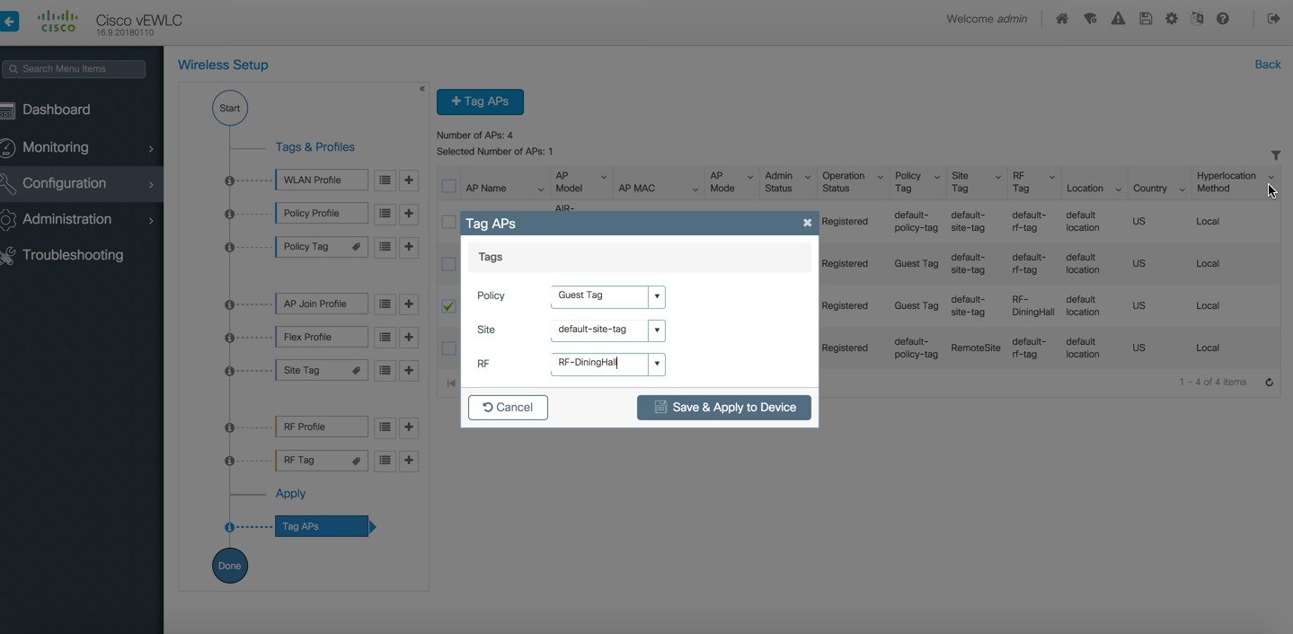 For remote sites, a site tag with a default/custom flex profile needs to be added.  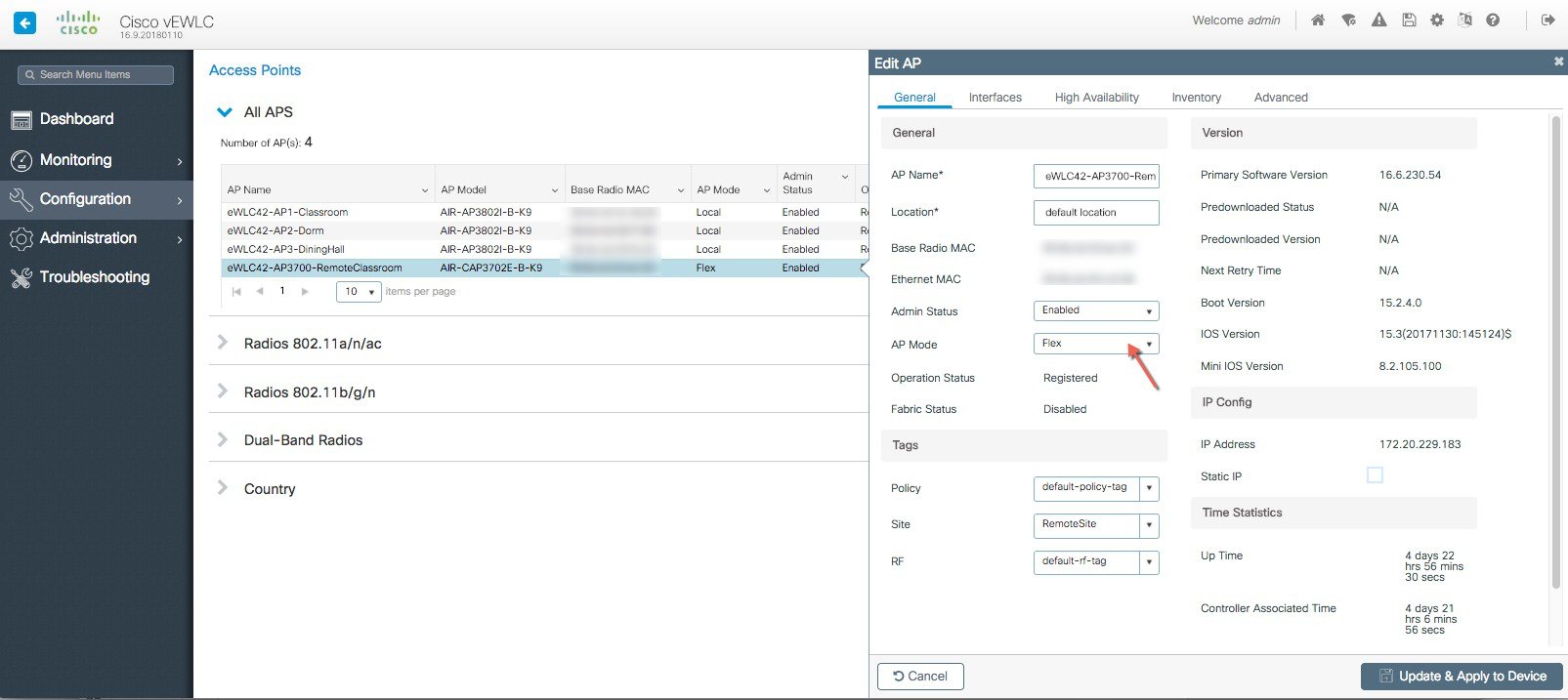 Once tagged with the remote site TAG, the APs will be converted to FlexConnect mode dynamically. Static Tagging of APs Optionally, APs can be tagged statically by specifying the MAC Address under Configuration > Tags & Profiles > Tags. 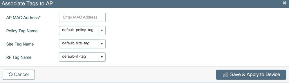 Static Tagging of APs using CSV file import Static tagging of APs using a CSV file for MAC address import is available on the page. 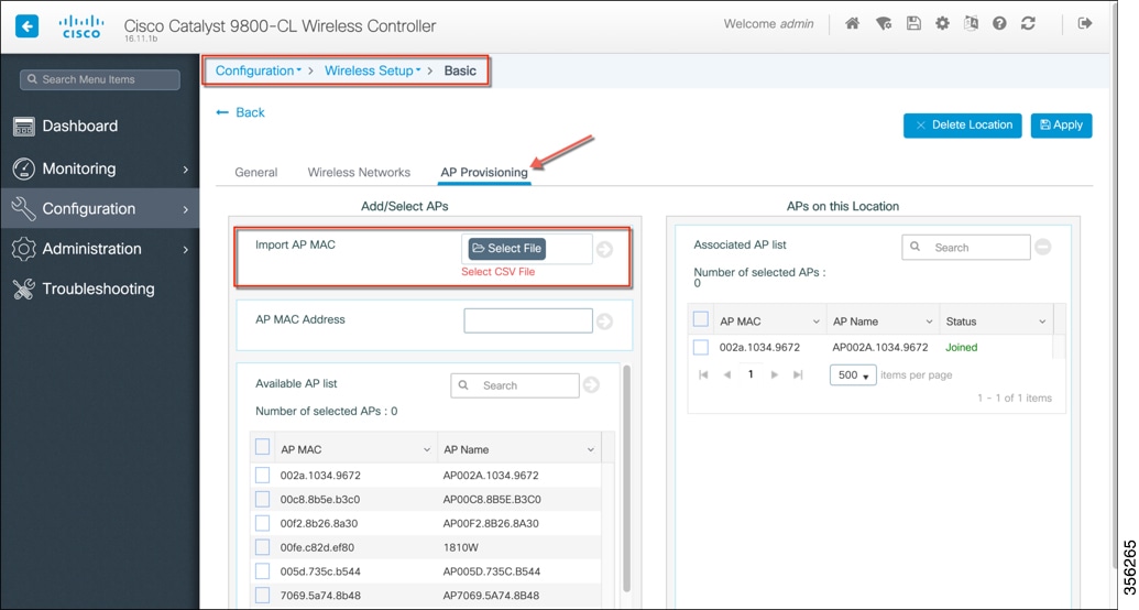 Regular-expression Based rules for AP Tagging Regular expression based rules can be configured to match on access point name and associate the appropriate policy, site and RF tags to access points.  Once the configuration is complete, the SSIDs start broadcasting and clients can now be connected. |
Additional Use case Examples
More involved use-cases can also be achieved with the configuration model detail in this document.
-
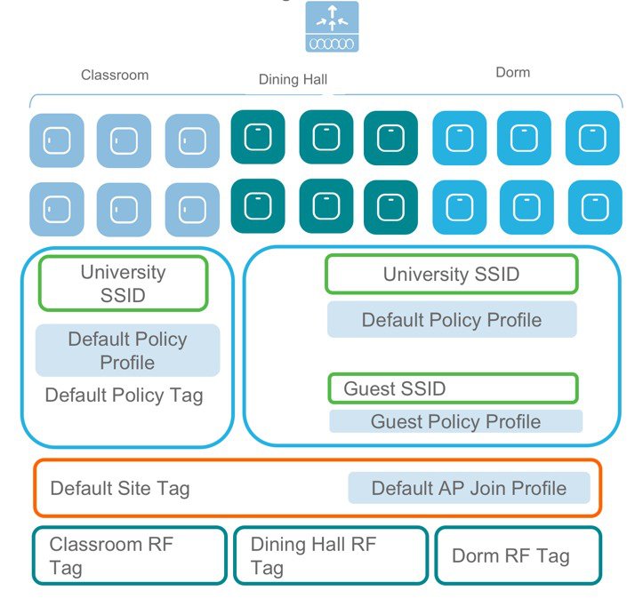
For example, a University Deployment with the following requirements can be deployed with profiles and tags as shown in the figure below:
-
Campus-wide University SSID for students and teachers
-
Dorms and Dining Halls to broadcast Guest SSID
-
Custom Guest policies for VLAN segregation
-
Custom RF characteristic of Dining Hall, classrooms and dorms
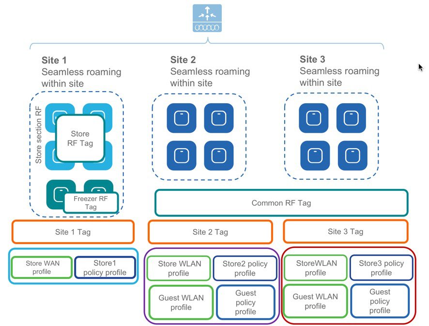
A multi-site retail deployment with the following requirements can be deployed with profiles and tags as shown in the figure below:
-
All sites should broadcast the same common SSID ‘Store’
-
All the sites should have same policies per SSID
-
Roaming is expected per store/flex-grp
-
All sites should have the same Site parameters
-
APs near freezer needs to have a different RF policy
-
Site 2 and 3 have additionally ‘Guest’ SSIDs
-
Independent Per site parameters
-
The Common SSID need to have store-specific policies
AireOS to Catalyst 9800 Wireless Controller Migration
Migration Web Tool
The migration tool provides configuration transition and is designed to translate AireOS configuration to the new configuration model for the Catalyst 9800 Wireless Controller. The migration tool is available as an offline tool or as an embedded tool in the C9800 Web UI. It uses as input the AireOS configuration commands (exported as a file to TFTP server) and AP Group information (through the “show run-config” command).
Procedure
|
Step 1 |
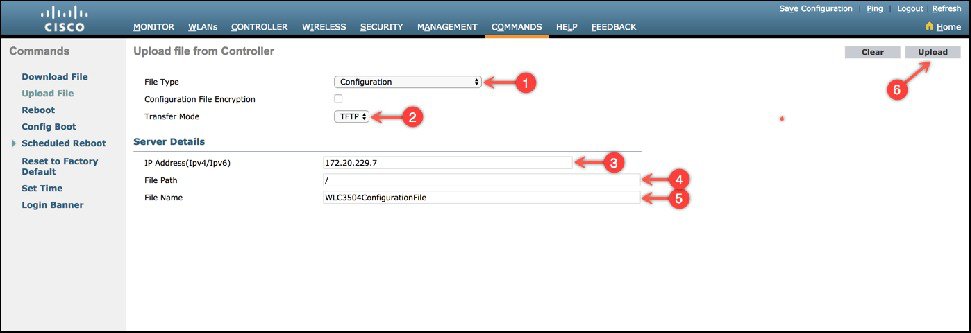
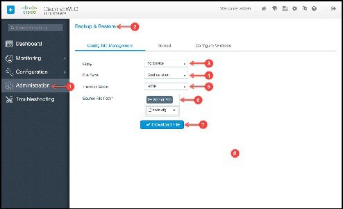
Export AireOS configuration to a TFTP server.
|
|
Step 2 |
Import the configuration into the tool as shown below, select and click Run. 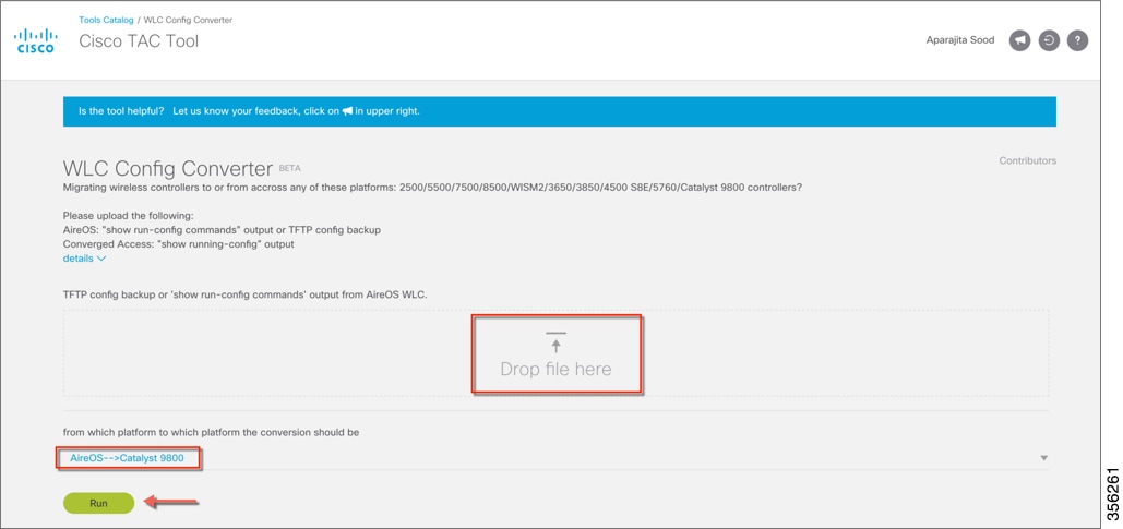 For further information about configuration migration between various wireless platforms, see https://cway.cisco.com/wlc-config-converter/ |
|
Step 3 |
The resultant output displays the configuration in 4 different buckets:
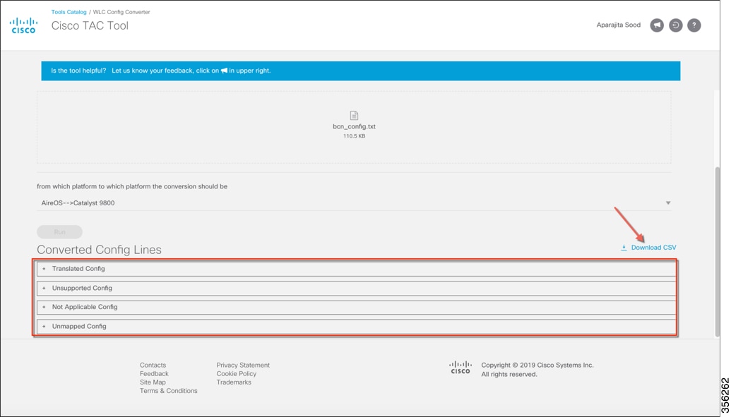
This configuration can also be exported for further analysis by clicking Download CSV. A detailed list of CLIs can be obtained by expanding the sections. |
|
Step 4 |
The tool displays the translated configuration in the form of a CLI output with the translated configuration and the corresponding AireOS configuration (preceded by a ‘!’ sign). Download the translated configuration, update shared secrets, passwords, IP and port information and prepare the file to be uploaded on the target C9800 controller 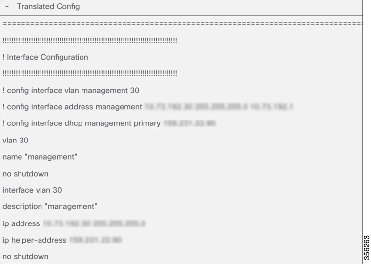 |
|
Step 5 |
Import Downloaded file to the C9800 controller to complete configuration migration.
|
AireOS Config Translator
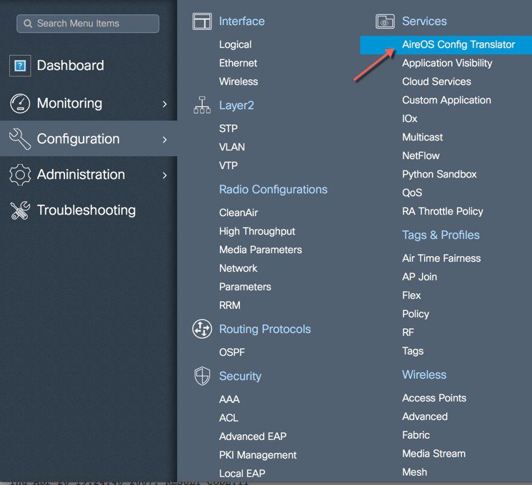
The AireOS config translator tool is natively built into the controller software and allows an AireOS configuration to be migrated to the Cisco Catalyst Wireless Controller configuration. To access the tool, go under Configuration > Services > AireOS Config Translator.
From an AireOS controller, export the configuration to a TFTP server and upload the file on the tool as shown below. The tool displays the translated configuration in the form of a CLI output with the translated configuration and the corresponding AireOS configuration (preceded by a ‘!’ sign).
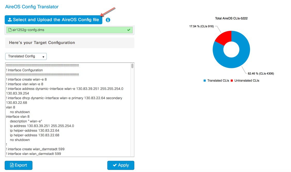
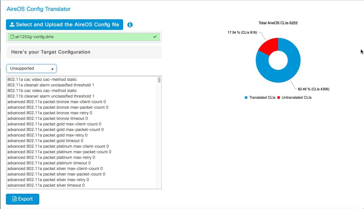
The configuration can then be exported as a file to make modifications such as re-entering passwords, IP addresses if changed and port details or, applied directly to the running configuration of the device. The pie chart on the right shows the break-down of translated vs. untranslated configs
Unsupported configuration is configuration that is currently unsupported on the controller and will be addressed in the upcoming releases.
Migration using Prime Infrastructure 3.5
Prime Infrastructure 3.5 can be used to migrate existing AireOS controllers to the new cisco catalyst 9800 wireless controller. Once these devices, both AireOS and Catalyst Wireless Controllers, have been discovered and added into the network devices databse of Prime, specific source AireOS controllers can be selected and their configuration migrated to the target controllers in a simple process as detailed below.
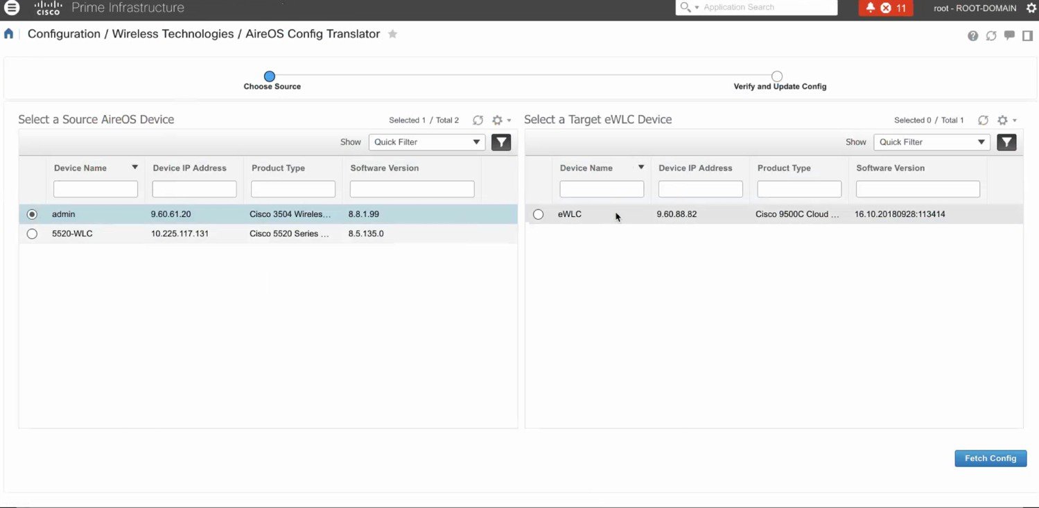
SELECT SOURCE AND TARGET WIRELESS CONTROLLERS
From the left hand menu, select the Source AireOS Wireless LAN Controller that needs to be migrated. On the right hand menu, choose the Wireless Controller that the translated configuration will be applied to. Click on Fetch Config to pull in the latest running configuration from the AireOS controller.
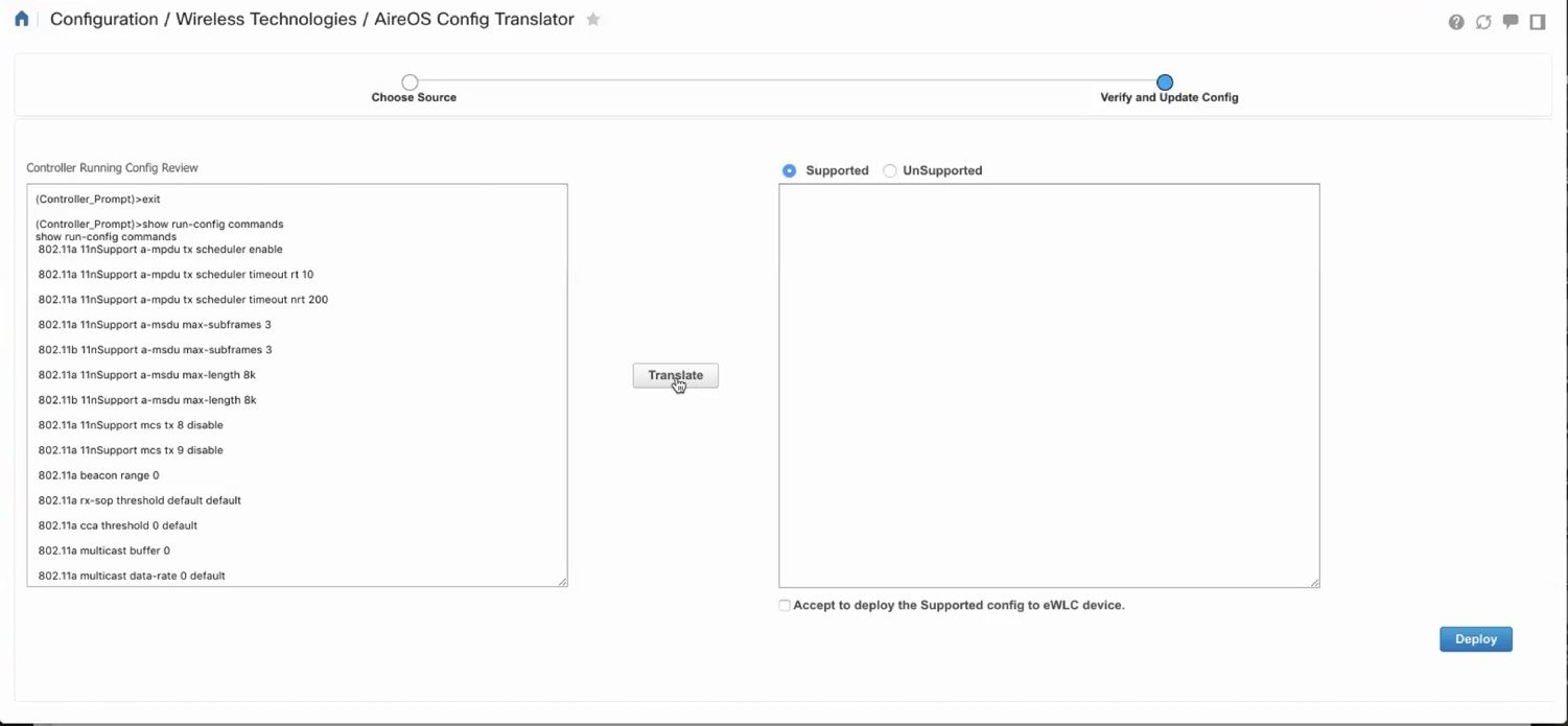
Once the configuration has been fetched, click on the translate button to start the translattion of AireOS to Catalyst 9800 configuration.
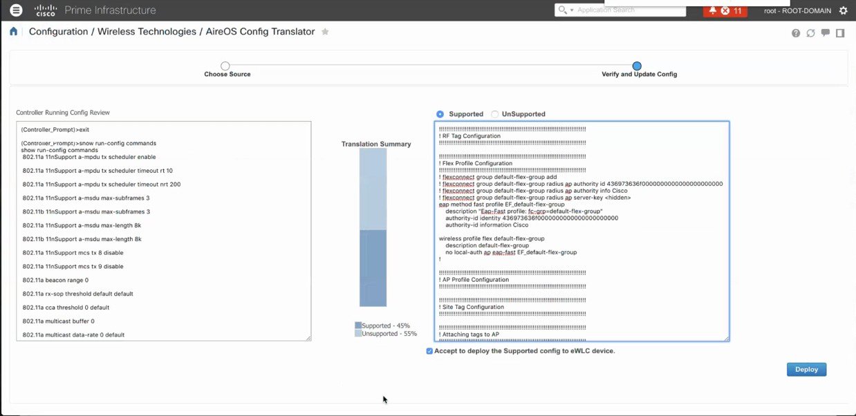
TRANSLATE AND VERIFY/UPDATE PASSWORDS, SHARED SECRETS, IP AND PORTS
The translation summary represents the percentage of supported/ translated vs. unsupported configuration. The translated configuration is displayed in the text box on the right hand side.
DEPLOY TRANSLATED AND UPDATED CONFIGURATION
The tool does not translate shared secret and passwords as these are stored encrypted and have to be re-entered by the user. For easy indentification of such configurations, they are highlighted and required to be edited manually by the user. Once the necessary edits have been made, click on the ‘Accept to deploy’ checkbox and click Deploy.
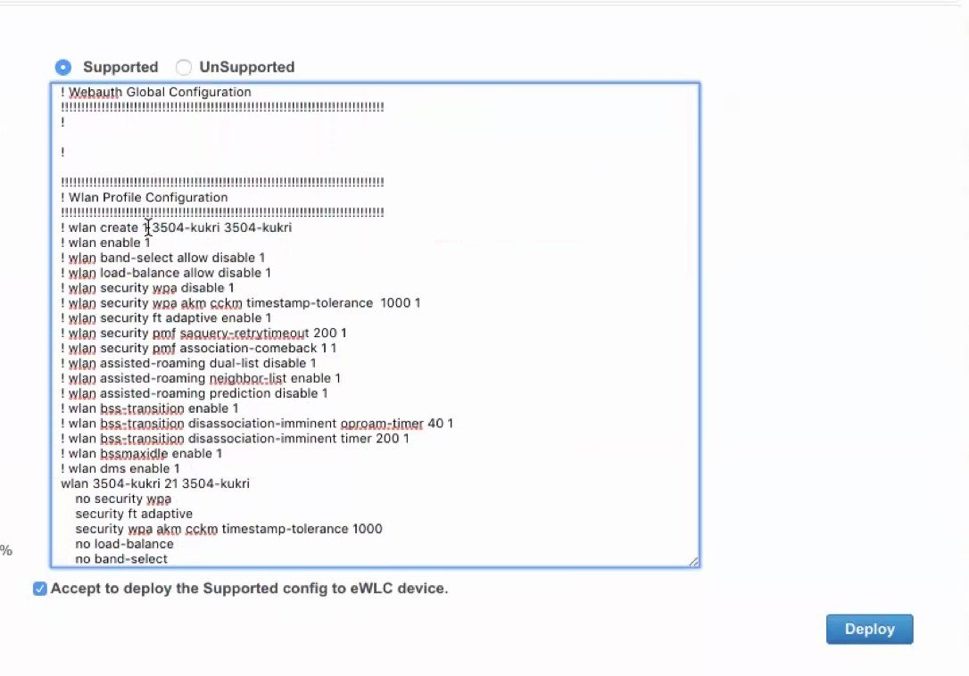
Once deployed, the configuration is pushed to the target wireless controller.

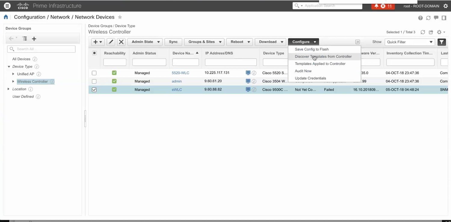
Optionally, templates can be discovered from the Cisco 9800 Catalyst Wireless Controller and re-used to apply configuration to other Wireless Controllers.
 Feedback