- Overview
- Choosing the Right Access Point
- Physical Hardware and Mounting Options
- Understanding Flexible Radio Assignment (software overview)
- Client Roaming in a Micro and Macro Cell
- Approved Antennas for Use with Access Points 2800 and 3800
- AP 2800 and AP 3800 Powering Options
- AP 3800 and Multigigabit Ethernet (mGig)
- New–B Regulatory Domain for US Theater
- Stadium and Harsh Environments
- Areas with High Vibration
- Related References
- Frequently Asked Questions (FAQ's)
Cisco Aironet Series 2800/3800 Access Point Deployment Guide
Bias-Free Language
The documentation set for this product strives to use bias-free language. For the purposes of this documentation set, bias-free is defined as language that does not imply discrimination based on age, disability, gender, racial identity, ethnic identity, sexual orientation, socioeconomic status, and intersectionality. Exceptions may be present in the documentation due to language that is hardcoded in the user interfaces of the product software, language used based on RFP documentation, or language that is used by a referenced third-party product. Learn more about how Cisco is using Inclusive Language.
- Updated:
- May 12, 2016
Chapter: Client Roaming in a Micro and Macro Cell
Client Roaming in a
Micro and Macro Cell
Understanding Macro and Micro Cells
In areas where the AP traditionally has a wide-area coverage clients connected close to the AP are the most spectrum efficient since they are in the near field and negotiate typically at the highest data rates while clients farther away compete at lower data rates. The lower rate clients that are farther away tend to take more airtime than the closer clients running at faster rates. This results in non-linear traffic and increases the overall channel utilization as clients compete for "airtime".
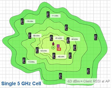
In the figure above, clients farther away are on the air more (sending longer, slower rate packets). The 2.4–GHz channels (channel 1) will typically propagate farther than 5–GHz so often the 2.4–GHz radio is redundant and in some cases is even turned off. So now the AP is covering a single 5–GHz cell in a Macro or large cell mode.
Using FRA, you can either automatically enable an additional 5–GHz cell using Radio Resource Management or you can manually decide that you would like to turn the XOR radio from its default 2.4– GHz to an additional 5–GHz cell.
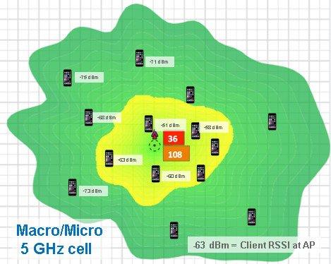
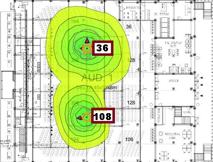
By optimizing the FRA to enable the access point to have two 5–GHz radios, this solves the problem of too much 2.4–GHz coverage while creating two completely RF diverse 5–GHz cells. This not only doubles the air time available to the 5–GHz clients, it also optimizes the client throughput by keeping like clients together for better spectrum efficiency.
Now instead of 60% channel utilization with the clients in near field competing for airtime from the slower farther away clients, like clients are now grouped with similar data rate characteristics.
Net result, channel utilization is now reduced to 20% on channel 36 and 24% on channel 108.
Currently both Macro (green) and Micro (yellow) cells use the same SSID by design; later releases will likely allow for different SSIDs.
- Client Roaming from a Macro to Micro Cell
- Client Roaming from a Micro to Macro Cell
- Micro and Macro cells on “I” Series Access Points
- RF Operations on “E/P” Series Access Points
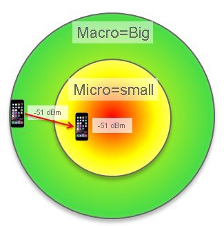
Client Roaming from a Macro to Micro Cell
The most likely scenario is that a client will associate to the Macro cell first as it will have the bigger footprint and transmitting at a greater RF power. So in the figure below, any client that has RSSI at the AP above the Micro cell threshold of -55 dBm will be moved into the Micro cell.
 Note | Note: -55 dBm is the default but configurable using the command line interface (CLI). For more on configuring these options see the RRM guide and other resources at http://www.cisco.com/c/en/us/support/wireless/wireless-lan-controller-software/products-technical-reference-list.html |
In addition to the threshold, if the client supports 802.11v, on association the AP will send an .11v BSS transition request with the Micro cell BSSID and the only candidate. If a non .11v client, it will send an .11k neighbor list and a disassociate packet. Other methods and optimizations are being investigated.
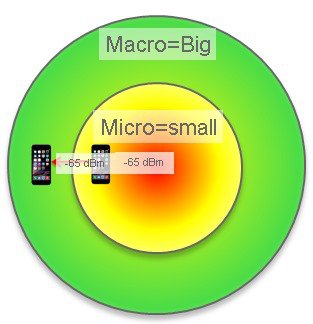
Client Roaming from a Micro to Macro Cell
When a client initially associate to the Micro cell first, while less likely but certainly possible based on device scan and channels heard. In this case, a client that has RSSI at the AP below the Macro cell threshold of -65 dBm will be moved into the Micro cell -65 dBm by default. This is also configurable by user CLI.
If the client supports 802.11v - on association, the AP will send an 11v BSS Transition request with the Macro cell BSSID as the only candidate.
For a non .11V client, the system sends an 11K neighbor list and a disassociate packet.
Micro and Macro cells on “I” Series Access Points
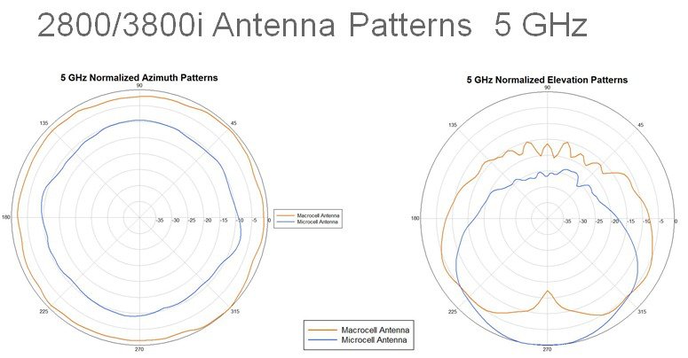
The AP 2800i and AP 3800i have integrated antennas and as such, when FRA is enabled and dual 5–GHz operation is selected, only the non-FRA radio can perform the role of a Macro cell or Micro cell. The XOR FRA radio when enabled for 5–GHz must operate using a much lower power and therefore must function as a Micro cell.
Note | The "E/P" Series with external antennas can operate in any combination of Micro or macro cells. |
Prior to FRA technology, access points like the AP 2700 and AP 3700 defined the dedicated radios in software as Radio 0 (2.4–GHz) and Radio 1 (5–GHz); if an additional radio like the WSM module was installed in the AP 3700 the third radio was defined as Radio 2, sometimes called "Slot 2".
Now with FRA, Radio 0 is the 2.4–GHz radio *OR* it can be a 5–GHz radio; hence the term XOR.
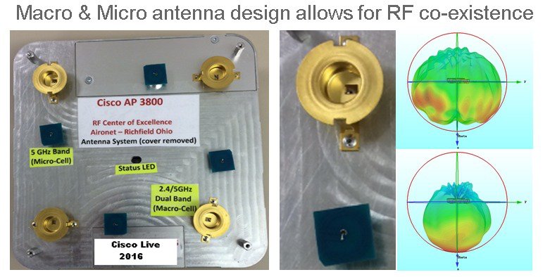
By default the FRA functions as a 2.4–GHz radio, so out of the box the AP behaves the same as a conventional AP 2700 and AP 3700 operating off the dual band Macro cell (large brass colored) antennas on the four corners in the figure below. Additionally, the non-FRA 5–GHz radio also shares the Macro cell antennas.
If you enable the FRA radio from 2.4–GHz to 5–GHz, the FRA radio can no longer use the Macro cell antenna on 2.4–GHz and automatically switches to another set of four Micro cell antennas. This is done because two 5–GHz radios cannot share the same antennas.
The Micro cell 5–GHz antennas are designed to co-exist in the near field of the Macro cell antennas with the following caveats.
-
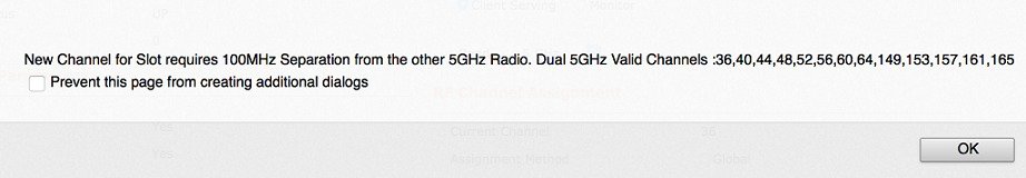
Channels must not be closer than 100–MHz (RRM prevents this).
-
The Micro cell antennas are horizontal polarity and higher gain to create a smaller cell foot print.
-
RF output power on the Micro cell is significantly reduced.
-
SSIDs must be the same (this may change in later releases).
RF Operations on “E/P” Series Access Points
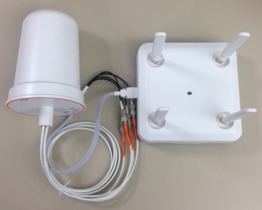
Unlike the integrated antenna models, the external antenna model units have four primary RP-TNC connectors on top of the device and an additional four RF connectors as well as digital via a new smart antenna connector.
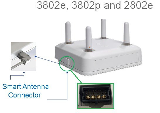
When the smart antenna connector is not used, the AP 2800 and AP 3800 "E/P" series function much like an AP 3700 where both the 2.4–GHz FRA radio and the integrated 5–GHz radio share the top RP-TNC connectors in a dual band mode.
Note | This is sometimes referred to as Dual Radiating Element (DRE) or dual band mode. |
However, once the smart antenna connector is inserted, the access point senses the presence of the new connector/antenna and automatically switches the FRA (XOR radio) from the top connector that was previously in 2.4 GHz/5 GHz DRE mode to the smart connector port. This allows the top connectors for the 5 GHz radio serving clients and the FRA radio is now free (regardless of mode) to use the smart connector for RF communications.
The flexibility to do this allows many different types of modes, from discrete single band operation (SRE) to DRE operation. The ability to change the antenna controls (sending different bands 2.4 GHz and 5 GHz out of different ports in SRE and/or DRE mode) is sometimes referred to as Cisco "Flexport" and was first introduced in the AP-1530 series.

The role of the XOR radio is selected in software, and the modes are Band, Client Serving or Monitor mode. This can be set manually or automatically if RRM control is desired.

If you change the band from 2.4 GHz to 5 GHz then you must have 100–MHz separation.
If the antenna has a smart antenna connector it allows the AP to sense what type of antenna is installed and configure the AP accordingly.
Using the smart antenna connector to RP-TNC adapter AIR-CAB002-DART-R the FRA (XOR) radio can now be used in many applications as the RF system on the FRA (XOR) radio will now use the four external RP-TNC connectors for a wide variety of application deployments.
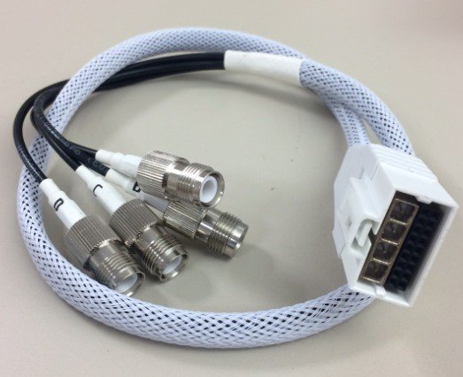
The smart RF antenna connector sometimes referred to as a DART carries the digital signals (18 mins) as well as the four analog RF ports from the XOR radio.
Note | The term DART is an Amphenol trademark name for this type of connector. |
Unlike the internal models, the smart connector allows both antenna systems to be located away from each other enabling deployments that cannot be done with the internal model. For example, the creation of two 5–GHz Macro cells is now possible in addition to separating the 5–GHz cells into different areas (think inside/outside) or different coverage areas in a factory or stadium.
Sometimes unique customer requirements dictate that 2.4–GHz RF operation be on one set of antennas and 5 GHz on a completely different set of antennas, and that is also possible.
Since both sets of antennae can be physically spaced apart, many new RF design opportunities become available allowing for many different types of new and unique installations.
Some deployment options include:
-
Omni and directional deployments (think hospital room and a long hallway) with one AP
-
Any combination of Micro and Macro cell deployments
-
Using stadium antennas, two different 5–GHz coverage cells can be done with 1 AP
-
High ceilings (factory and warehouse deployments) can use back to back 6 dBi Patch antennas
-
AP using 2x 5–GHz radio can double the coverage with the addition of one antenna
-
Conference centers and other locations can double capacity on existing Ethernet cable plan
-
One access point can support both indoor and outdoor deployments
-
Access point can serve 5–GHz clients while performing full 2.4 & 5–GHz wireless monitor radio
When using the smart antenna connector and dual 5–GHz mode the caveats are:
-
Channels must not be closer than 100–MHz
-
Antennas should not be mounted so that energy from one antenna is directed into another
-
Ideally if one antenna is Omni then 6 ft or 2 meter physical separation
-
Antennas may be closer if used in Micro cell (very low power) is used
-
Any combination of Micro/Macro can be used as long as physical isolation exists
-
SSIDs must be the same (this may change in later releases)
 Feedback