Virtual Infrastructure Manager Installation Automation
Introduction
Leveraging RedHat and OpenStack’s TripleO project concepts, UAS supports the ability to automate the deployment of both the virtual infrastructure manager (VIM, the Triple O Overcloud) and the VIM Orchestrator (the TripleO Undercloud).
Installing the VIM Orchestrator and the VIM involves deploying the following components as VMs on a RedHat Enterprise Linux (RHEL) server:
-
AutoIT
-
AutoDeploy
-
OpenStack Platform Director (OSP-D)
VIM Orchestrator and VIM settings are maintained in configuration files which are used by AutoDeploy.
AutoDeploy processes the VIM Orchestrator configuration and works with AutoIT to automate the deployment of a VM running OSP-D which serves as the Undercloud. Once this operation is successful, AutoDeploy processes the VIM configuration and works with AutoIT to deploy the OpenStack Overcloud.
Notes:
-
This functionality is supported only with Ultra M deployments based on OSP 10 and that leverage the Hyper-Converged architecture.
-
Refer to Pre-Virtual Infrastructure Manager Installation Verification for pre-requisites pertaining to this feature.
VIM Installation Automation Overview
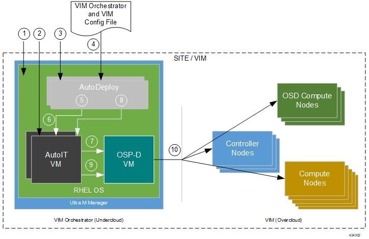
Figure 1 provides an overview of the deployment automation process. Details are provided in Table 1. This information assumes that all prerequisite hardware has been installed, cabled, and configured.
 Important |
The workflow information in this section assumes a new deployment scenario. If you are using this feature in relation with an upgrade process, please contact your support representative for complete details. |
| Callout | Description |
|---|---|
|
1 |
Install RedHat Enterprise Linux (RHEL) operating system on bare metal hardware (Ultra M Manager Node). |
|
2 |
Deploy the AutoIT VMs. |
|
3 |
Deploy the AutoDeploy VMs. |
|
4 |
Prepare the file containing the VIM Orchestrator and VIM. This file is used is used by AutoDeploy to initiate the OSP-D VM deployment process and to bring up the VIM. This file includes all of the configuration information required to deploy OSP-D VM and VIM including configurations for constructs such as secure tokens, package images, NFVI point-of-presence descriptors (nfvi-popd), the VIM Orchestrator descriptor (vim-orchd), and VIM role and node information. Refer to Sample VIM Orchestrator and VIM Configuration File for more information. |
|
5 |
On the AutoDeploy VM, load, commit, and then activate the configuration file prepared in the previous step. |
|
6 |
AutoDeploy passes data from the activated configuration to AutoIT requesting that it deploy the OSP-D VM for the Undercloud. Refer to Activate the VIM Orchestrator and VIM Deployment for more information. |
|
7 |
AutoIT deploys the OSP-D VM which serves as the Undercloud. |
|
8 |
AutoDeploy passes VIM data from the activated configuration to AutoIT for delivery to the OSP-D VM responsible for installing the VIM. |
|
9 |
AutoIT initiates the VIM installation by passing parameters received from AutoDeploy to the OSP-D VM. |
|
10 |
The OSP-D VM installs the VIM per the configuration requirements. |
Once all of the VIM servers have been successfully deployed, the process of deploying the VNF can begin as described in VNF Deployment Automation.
Pre-Virtual Infrastructure Manager Installation Verification
Prior to installing the virtual infrastructure manager (VIM) and the VIM Orchestrator, please ensure that the following is true:
-
Ensure that all required hardware is installed, powered on, cabled and configured according to the information and instructions in the Ultra M Solutions Guide. Refer to the following sections in that document:
-
Hardware Specifications
-
Install and Cable the Hardware
-
Configure the Switches
-
Prepare the UCS C-Series Hardware
-
-
Ensure that all required software is available and that you have access to the Cisco-provided USP ISO image. Refer to the Software Specifications section of the Ultra M Solutions Guide for more details.
Install the VIM Orchestrator
The initial part of the Virtual Infrastructure Manager installation automation process is to install the VIM Orchestrator. You cannot install the VIM until after the VIM Orchestration installation is successful.
Important |
Before proceeding, ensure that all of the items in Pre-Virtual Infrastructure Manager Installation Verification have been verified. |
To install the VIM Orchestrator:
-
Prepare the VIM Orchestrator and VIM Configuration File based on your deployment requirements.
Install and Configure RHEL
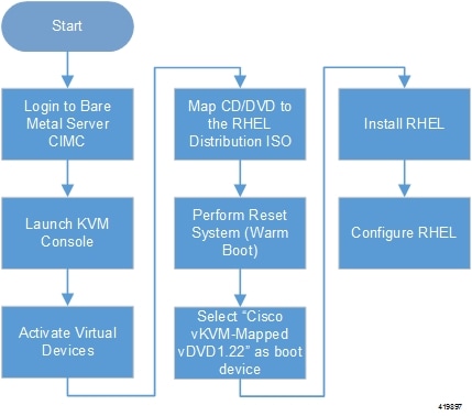
As described in VIM Installation Automation Overview, the VIM Orchestrator (OSP-D) is deployed as a VM on top of RHEL. Figure 1 illustrates the process for installing RHEL.
General RHEL installation information and procedures are located in the product documentation:
Prior to installing RHEL, refer to Table 1 for settings required for the VIM Orchestrator installation in Ultra M.
Note |
Table 1 assumes that you are using the product’s graphical user interface (GUI) for Red Hat installation. |
|
Parameters and Settings |
Description |
||
|---|---|---|---|
|
Installation Summary > Language Support |
|||
|
English > English (United States) |
Sets the language to English and the region to United States. |
||
|
Installation Summary > Software Selection |
|||
|
Base Environment = Virtualization Host Add-Ons for Selected Environment = Virtualization Platform |
|||
|
Installation Summary > Network & Host Name |
|||
|
Host name |
Configure the desired host name. |
||
|
Installation Summary > Network & Host Name > Ethernet (enp6s0f0) > Configure > IPv4 Setting |
|||
|
IP Address Netmask Gateway DNS Server Search Domain |
Configure and save settings for the network interface by which the server can be accessed externally.
|
||
|
Installation Summary > Installation Destination > CiscoUCSC-MRAID12G (sda) > I will configure partitioning > Click here to create them automatically |
|||
|
Select all partitions, then click “-“ / = 100GB /var = 500GB /swap = 100GB /home = remaining space /boot = 1GB |
Removes any previously configured partitions and creates partitions with the required sizes.
|
||
|
Installation Summary > KDUMP |
|||
|
kdump = disabled |
It is recommended that kdump be disabled. |
||
|
Installation Summary > Begin Installation > User Settings |
|||
|
Root Password |
Configure and confirm the root user password. |
||
|
Create user “nfvi” |
Creates a new user account. This account is used during the VIM Orchestration installation to log onto the Ultra M Manager Node.
|
||
To install and configure RHEL:
-
Follow the CIMC processes on the bare metal server as identified in Figure 1.
-
Select the option to install Red Hat Enterprise Linux to begin the installation.
-
Configure the settings identified in Table 1.
-
Begin the installation and configure the User Setting identified in Table 1.
-
Click Reboot once the installation is complete.
-
Log in to RedHat as the nfvi user.
-
Set password-less sudo access for nfvi.
echo "nfvi ALL=(root) NOPASSWD:ALL" | tee -a /etc/sudoers.d/nfvichmod 0440 /etc/sudoers.d/nfvi -
Configure the network interfaces and network bridges.
Important
If any of the network interface or bridge configuration files do not exist, create the related configuration files. Example configuration files are provided in Example RedHat Network Interface and Bridge Configuration Files.
-
Configure the eno2 interface by appending the following parameters to the /etc/sysconfig/network-scripts/ifcfg-eno2 file.
<--SNIP-->DEVICE=eno2 ONBOOT=yes BRIDGE=br-ex NM_CONTROLLED=no NETMASK= <netmask> GATEWAY= <gateway_address> -
Configure the eno1 interface by appending the following parameters to the /etc/sysconfig/network-scripts/ifcfg-eno1 file.
<--SNIP-->DEVICE=eno1 ONBOOT=yes BRIDGE=br-ctlplane NM_CONTROLLED=no -
Configure the br-ex network bridge by adding the following parameters to the /etc/sysconfig/network-scripts/ifcfg-br-ex file.
<--SNIP-->DEVICE=br-ex DEFROUTE=yes TYPE=Bridge ONBOOT=yes BOOTPROTO=static NM_CONTROLLED=no DELAY=0 IPADDR= <external_ip_address> NETMASK= <netmask> GATEWAY= <gateway_address> PREFIX="24" DNS1= "<DNS_server_address>" DOMAIN= "<domain_name>" IPV4_FAILURE_FATAL="yes" -
Configure the br-ctlplane bridge by adding the following parameters to the /etc/sysconfig/network-scripts/ifcfg-br-ctlplane file.
<--SNIP-->DEFROUTE=yes TYPE=Bridge ONBOOT=yes BOOTPROTO=static NM_CONTROLLED=no DELAY=0 DEVICE=br-ctlplane
Caution
Once configured, it is recommended that you do not make any changes to the network interface or bridge configuration. Doing so will require that you redeploy AutoIT and AutoDeploy.
-
-
Create and prepare the directories required for installing the UAS components.
sudo mkdir -p /var/cisco/isossudo mkdir -p /var/cisco/diskssudo chmod 777 -R /var/cisco -
Reboot the bare metal server.
sudo reboot -
Login as a root user upon reboot.
Important
If the server is not accessible via the configured IP address, login into the server’s KVM console and troubleshoot the configuration.
-
Validate the network configuration.
ifconfig | moreExample output:
br-ctlplane: flags=4163<UP,BROADCAST,RUNNING,MULTICAST> mtu 1500 inet6 fe80::22c:c8ff:fed9:f176 prefixlen 64 scopeid 0x20<link> ether 00:2c:c8:d9:f1:76 txqueuelen 1000 (Ethernet) RX packets 52 bytes 7044 (6.8 KiB) RX errors 0 dropped 0 overruns 0 frame 0 TX packets 8 bytes 648 (648.0 B) TX errors 0 dropped 0 overruns 0 carrier 0 collisions 0 br-ex: flags=4163<UP,BROADCAST,RUNNING,MULTICAST> mtu 1500 inet 172.25.22.59 netmask 255.255.255.0 broadcast 172.25.22.255 inet6 fe80::22c:c8ff:fed9:f177 prefixlen 64 scopeid 0x20<link> ether 00:2c:c8:d9:f1:77 txqueuelen 1000 (Ethernet) RX packets 1394 bytes 122906 (120.0 KiB) RX errors 0 dropped 0 overruns 0 frame 0 TX packets 717 bytes 71762 (70.0 KiB) TX errors 0 dropped 0 overruns 0 carrier 0 collisions 0 eno1: flags=4163<UP,BROADCAST,RUNNING,MULTICAST> mtu 1500 inet6 fe80::22c:c8ff:fed9:f176 prefixlen 64 scopeid 0x20<link> ether 00:2c:c8:d9:f1:76 txqueuelen 1000 (Ethernet) RX packets 57 bytes 8072 (7.8 KiB) RX errors 0 dropped 0 overruns 0 frame 0 TX packets 16 bytes 1296 (1.2 KiB) TX errors 0 dropped 0 overruns 0 carrier 0 collisions 0 device memory 0xc7000000-c70fffff eno2: flags=4163<UP,BROADCAST,RUNNING,MULTICAST> mtu 1500 inet6 fe80::22c:c8ff:fed9:f177 prefixlen 64 scopeid 0x20<link> ether 00:2c:c8:d9:f1:77 txqueuelen 1000 (Ethernet) RX packets 1497 bytes 148860 (145.3 KiB) RX errors 0 dropped 0 overruns 0 frame 0 TX packets 726 bytes 72476 (70.7 KiB) TX errors 0 dropped 0 overruns 0 carrier 0 collisions 0 device memory 0xc6f00000-c6ffffff enp6s0: flags=4163<UP,BROADCAST,RUNNING,MULTICAST> mtu 1500 ether 00:2c:c8:68:3b:ec txqueuelen 1000 (Ethernet) RX packets 1 bytes 68 (68.0 B) RX errors 0 dropped 0 overruns 0 frame 0 TX packets 0 bytes 0 (0.0 B) TX errors 0 dropped 0 overruns 0 carrier 0 collisions 0 enp7s0: flags=4163<UP,BROADCAST,RUNNING,MULTICAST> mtu 1500 ether 00:2c:c8:68:3b:ed txqueuelen 1000 (Ethernet) RX packets 1 bytes 68 (68.0 B) RX errors 0 dropped 0 overruns 0 frame 0 TX packets 0 bytes 0 (0.0 B) TX errors 0 dropped 0 overruns 0 carrier 0 collisions 0 lo: flags=73<UP,LOOPBACK,RUNNING> mtu 65536 inet 127.0.0.1 netmask 255.0.0.0 inet6 ::1 prefixlen 128 scopeid 0x10<host> loop txqueuelen 1 (Local Loopback) RX packets 84 bytes 6946 (6.7 KiB) RX errors 0 dropped 0 overruns 0 frame 0 TX packets 84 bytes 6946 (6.7 KiB) TX errors 0 dropped 0 overruns 0 carrier 0 collisions 0 virbr0: flags=4099<UP,BROADCAST,MULTICAST> mtu 1500 inet 192.168.122.1 netmask 255.255.255.0 broadcast 192.168.122.255 [root@rhel-baremetal nfvi]# brctl show bridge name bridge id STP enabled interfaces br-ctlplane 8000.002cc8d9f176 no eno1 br-ex 8000.002cc8d9f177 no eno2 virbr0 8000.5254003d7549 yes virbr0-nic -
Perform the RHEL subscription-manager registration.
From Content Delivery Network (CDN) servers:
sudo subscription-manager config --server.proxy_hostname=<proxy_url> --server.proxy_port=80subscription-manager register --username <username> --password <password>subscription-manager attach -autosudo subscription-manager statusFrom Satellite Servers:
rpm -Uvh http://<satellite_server_domain>/pub/katello-ca-consumer-latest.noarch.rpmsubscription-manager register --org="<organization>" --activationkey="<activation_key>"Example output:
+-------------------------------------------+ System Status Details +-------------------------------------------+ Overall Status: Current -
Install the virtualization packages.
yum install virt-install -yExample output:
Loaded plugins: langpacks, product-id, search-disabled-repos, subscription-manager
rhel-7-server-rpms                                                          | 3.5 kB  00:00:00
(1/3): rhel-7-server-rpms/7Server/x86_64/group                              | 709 kB  00:00:01
(2/3): rhel-7-server-rpms/7Server/x86_64/updateinfo                         | 2.3 MB  00:00:02
(3/3): rhel-7-server-rpms/7Server/x86_64/primary_db                         |  42 MB  00:00:16
Resolving Dependencies
Loaded plugins: langpacks, product-id, search-disabled-repos, subscription-manager
rhel-7-server-rpms | 3.5 kB 00:00:00
(1/3): rhel-7-server-rpms/7Server/x86_64/group | 709 kB 00:00:01
(2/3): rhel-7-server-rpms/7Server/x86_64/updateinfo | 2.3 MB 00:00:02
(3/3): rhel-7-server-rpms/7Server/x86_64/primary_db | 42 MB 00:00:16
Resolving Dependencies
yum install virt-viewer -yLoaded plugins: langpacks, product-id, search-disabled-repos, subscription-manager Resolving Dependencies --> Running transaction check ---> Package virt-viewer.x86_64 0:5.0-7.el7 will be installed -
Install the Python bindings to the OpenStack Compute API.
yum install python-novaclient -y -
Install the OpenStack networking API client.
yum install python-neutronclient -y -
Proceed to Onboard the USP ISO.
Onboard the USP ISO
The files required to deploy the USP components are distributed as RPMs (called “bundles”) in a single ISO package. They are maintained using YUM on the Ultra M Manager Node. The following bundles are part of the ISO:
|
USP Bundle Name |
Description |
|---|---|
|
usp-em-bundle |
The Element Manager (EM) Bundle RPM containing images and metadata for the Ultra Element Manager (UEM) module. |
|
usp-uas-bundle |
The Ultra Automation Services Bundle RPM containing AutoIT-VNF, AutoDeploy, AutoVNF, Ultra Web Services (UWS), and other automation packages. |
|
usp-ugp-bundle |
The Ultra Gateway Platform (UGP) Bundle RPM containing images for Ultra Packet core (VPC-DI). This bundle contains non-trusted images. |
|
usp-vnfm-bundle |
The VNFM Bundle RPM containing an image and a boot-up script for ESC (Elastic Service Controller). |
|
usp-yang-bundle |
The Yang Bundle RPM containing YANG data models including the VNFD and VNFR. |
|
usp-auto-it-bundle |
The bundle containing the AutoIT packages required to deploy the UAS. |
In addition to the bundles, the ISO bundle also includes scripts used to deploy the bundles including UAS.
Important |
This procedure is not necessary if you are deploying a VNF on a Hyper-Converged Ultra M mode and have already deployed the VIM Orchestrator and the VIM using the information and instructions in Virtual Infrastructure Manager Installation Automation. |
Important |
Before attempting to deploy the Ultra M Manager Node, ensure that the USP Installation Prerequisites have been met. |
To onboard the ISO package:
-
Log on to the Ultra M Manager Node.
-
Download the USP ISO bundle and related files pertaining to the release.
-
Create a mount point on the Ultra M Manager Node and mount the ISO package:
mkdir /var/usp-iso -
Mount the USP ISO.
sudo mount -t iso9660 -o loop <ISO_download_directory>/<ISO_package_name> /var/usp-isoExample: The following command mounts the ISO bundle called usp-5_5_0-1255.iso located in a directory called 5_5_0-1283 to /var/usp-iso:
sudo mount -t iso9660 -o loop 5_5_0-1064/usp-5_5_0-1064.iso /var/usp-isomount: /dev/loop1 is write-protected, mounting read-only -
Verify the mount configuration.
df –hExample output:
Filesystem Size Used Avail Use% Mounted on /dev/sda2 187G 178G 316M 100% / devtmpfs 63G 0 63G 0% /dev tmpfs 63G 4.0K 63G 1% /dev/shm tmpfs 63G 1.4M 63G 1% /run tmpfs 63G 0 63G 0% /sys/fs/cgroup /dev/sda1 477M 112M 336M 25% /boot tmpfs 13G 0 13G 0% /run/user/0 /dev/loop1 4.2G 4.2G 0 100% /var/usp-iso >>>>> -
Proceed to Extract the UAS Bundle.
Extract the UAS Bundle
Once the USP ISO has been mounted, the UAS bundle must be extracted from the ISO in order to prepare the configuration files required for deployment.
Note |
These instructions assume you are already logged on to the server on which AutoIT, AutoDeploy, and VIM-Orchestrator VMs are to be installed and that the USP ISO has been mounted. |
To extract the UAS bundle:
-
Navigate to the tools directory within the ISO mount.
cd /var/usp-iso/tools/ -
Launch the usp-uas-installer.sh script.
sudo ./usp-uas-installer.shThe script extracts the files that comprise the UAS bundle to /opt/cisco/usp/uas-installer.
-
Verify that files have been extracted.
Example output:
ll /opt/cisco/usp/uas-installertotal 20
drwxr-xr-x 5 root root 4096 Aug 18 23:42 ./
drwxr-xr-x 6 root root 4096 Aug 18 23:42 ../
drwxr-xr-x 5 root root 4096 Aug 18 23:42 common/
drwxr-xr-x 2 root root 4096 Aug 18 23:42 images/
drwxr-xr-x 2 root root 4096 Aug 18 23:42 scripts/
ll /opt/cisco/usp/uas-installer/images/total 711940 drwxr-xr-x 2 root root 4096 Aug 18 23:42 ./ drwxr-xr-x 5 root root 4096 Aug 18 23:42 ../ -rw-r--r-- 1 root root 729010688 Aug 17 23:29 usp-uas-1.0.0-1074.qcow2ll /opt/cisco/usp/uas-installer/scripts/ total 80-rwxr-xr-x. 1 root root 806 Aug 29 18:14 auto-deploy-booting.sh -rwxr-xr-x. 1 root root 5460 Aug 29 18:14 autoit-user.py -rwxr-xr-x. 1 root root 811 Aug 29 18:14 auto-it-vnf-staging.sh -rwxr-xr-x. 1 root root 4762 Aug 29 18:14 encrypt_account.sh -rwxr-xr-x. 1 root root 3945 Aug 29 18:14 encrypt_credentials.sh -rwxr-xr-x. 1 root root 14031 Aug 29 18:14 start-ultram-vm.py -rwxr-xr-x. 1 root root 14605 Aug 29 18:14 uas-boot.py -rwxr-xr-x. 1 root root 5384 Aug 29 18:14 uas-check.py -rwxr-xr-x. 1 root root 11283 Aug 29 18:14 usp-tenant.py -
Proceed to Deploy AutoIT.
Deploy AutoIT
AutoIT deployment is facilitated through a script. The script relies on user inputs to perform pre-requisite configurations including whether or not to deploy with HA support and account encryptions. Additionally, the script removes existing AutoIT deployments that may already exist.
The following information is required to execute the script:
-
AutoIT VM Login Password for ID 'ubuntu': The password for the default user account, which is named ubuntu.
-
AutoIT API Access password for 'admin': The password for the ConfD administrator user, which is named admin.
-
AutoIT API Access password for 'oper': The password for the ConfD operator user, which is named oper.
-
AutoIT API Access password for 'security-admin': The password for the ConfD security administrator user, which is named security-admin.
-
Hostname: The hostname assigned to the AutoIT VM.
-
Image (QCOW2): The path and file name for the UAS qcow2 file. For example:
/opt/cisco/usp/uas-installer/images/usp-uas-1.0.0-1074.qcow2
-
External Network HA VIP : The VIP address to be assigned to AutoIT’s external network interface.
-
External Network Details:
-
IP Address: The IP address to be assigned to AutoIT VMs’ external network interface. If AutoIT is deployed with HA support, you are prompted to enter separate external IP addresses for both the active and redundant VMs.
-
Gateway: The gateway assigned to AutoIT’s external network interface.
-
Netmask: The mask to be assigned to AutoIT’s external network interface.
-
-
Provisional Network HA VIP: The VIP address to be assigned to AutoIT's provisional network interface.
-
Provisioning Network Details:
-
IP Address: The IP address to be assigned to the provisioning network interface. Within Hyper-Converged Ultra M models, this interface is used by the Ultra M Health Monitoring function.
If AutoIT is deployed with HA support, you are prompted to enter separate IP provisioning addresses for both the active and redundant VMs.
-
Netmask: The netmask to be assigned to the provisioning network interface.
-
Important |
|
The script allocates the following resources to the AutoIT VM:
-
2 VCPUs
-
8 GB RAM
-
80 GB Root Disk
Important |
These instructions assume a bare-metal installation and that you are already logged on to the server on which AutoIT, AutoDeploy, and VIM-Orchestrator VMs are to be installed and on which the USP ISO has been mounted. |
To deploy the AutoIT VM:
-
Navigate to the /opt/cisco/usp/uas-installer/scripts directory:
cd /opt/cisco/usp/uas-installer/scripts -
Execute the boot_uas.py script with the desired options:
./boot_uas.py --kvm --autoit --ha
Important
The above command deploys AutoIT with HA support which is recommended for use within Ultra M solutions. Remove the --ha if you do not wish to implement HA support for AutoIT.
There are a number of options that can be specified when deploying AutoIT. Refer to boot_uas.py Help for details. Some notes are below.
Note
-
The above command deploys AutoIT with HA support. Remove the --ha if you do not wish to implement HA support for AutoIT.
-
If you wish to configure syslog functionality for AutoIT, you must specify the IP address, TCP/UDP port, and severity level for one or more collection servers. The following command example configures two collection servers.
./boot_uas.py --kvm --autoit --ha --syslog-ip 192.168.2.1 --port 514 --severity 5 --syslog-ip 192.168.2.2 --port 514 --severity 5You can set the severity level to one of the following values:
-
0: emerg, panic
-
1: alert
-
2: crit
-
3: err.error
-
4: warning, warn
-
5: notice
-
6: info
-
7: debug
-
-
-
Enter the information requested by the script for your deployment.
The script displays progress information. For example:
2018-01-24 16:06:17,355 - '/home' disk capacity is 1807 GB Loaded plugins: langpacks, product-id 2018-01-24 16:06:17,397 - Package 'virt-install' is present 2018-01-24 16:06:17,397 - Package 'libvirt' is present 2018-01-24 16:06:17,397 - Package 'virt-viewer' is present 2018-01-24 16:06:17,397 - Interface 'br-ex' is UP 2018-01-24 16:06:17,397 - Interface 'br-ctlplane' is UP 2018-01-24 16:06:17,398 - Removing old deployment 'AutoIT_instance_0', if it exists 2018-01-24 16:06:19,921 - Removing old deployment 'AutoIT_instance_1', if it exists 2018-01-24 16:06:19,946 - Using instance 'AutoIT_instance_0' at location '/home/cisco/AutoIT/instance_0' 2018-01-24 16:06:19,946 - Staging configuration ISO 2018-01-24 16:06:19,951 - Completed configuration ISO /home/cisco/AutoIT/instance_0/cfg.iso 2018-01-24 16:06:19,951 - Preparing root disk '/home/cisco/AutoIT/instance_0/uas.qcow2' 2018-01-24 16:06:20,378 - Resizing disk to '80GB' 2018-01-24 16:06:33,417 - Starting deployment 'AutoIT_instance_0' 2018-01-24 16:06:34,124 - Started deployment 'AutoIT_instance_0' successfully 2018-01-24 16:06:34,125 - Using instance 'AutoIT_instance_1' at location '/home/cisco/AutoIT/instance_1' 2018-01-24 16:06:34,125 - Staging configuration ISO 2018-01-24 16:06:34,130 - Completed configuration ISO /home/cisco/AutoIT/instance_1/cfg.iso 2018-01-24 16:06:34,130 - Preparing root disk '/home/cisco/AutoIT/instance_1/uas.qcow2' 2018-01-24 16:06:34,557 - Resizing disk to '80GB' 2018-01-24 16:06:42,629 - Starting deployment 'AutoIT_instance_1' 2018-01-24 16:06:43,360 - Started deployment 'AutoIT_instance_1' successfully -
Verify that the AutoIT VM is running.
virsh list -allExample command output:
Id Name State ---------------------------------------------------- 487 AutoIT_instance_0 running 488 AutoIT_instance_1 running -
Check the status of AutoIT.
-
Log on to the master AutoIT VM.
confd_cli -C -u adminExample command output:
Welcome to the ConfD CLI admin connected from 127.0.0.1 using console on autoit1-0 -
View the status.
show uasExample command output:
uas version               6.0.0
uas state                 active
uas external-connection-point 172.28.185.132
INSTANCE IP     STATE  ROLE
-------------------------------------
172.28.185.133  alive  CONFD-MASTER
172.28.185.134  alive  CONFD-SLAVE

NAME           LAST HEARTBEAT
------------------------------------
AutoIT-MASTER  2018-01-24 21:24:30
USPCFMWorker   2018-01-24 21:24:30
USPCHBWorker   2018-01-24 21:24:30
USPCWorker     2018-01-24 21:24:30
-
-
Proceed to Deploy AutoDeploy.
Deploy AutoDeploy
Important |
The information and instructions provided here are only applicable when AutoDeploy is used in the VIM Orchestrator installation process. |
AutoDeploy deployment is facilitated through a script. The script relies on user inputs to perform pre-requisite configurations including whether or not to deploy with HA support and account encryptions. Additionally, the script removes existing AutoDeploy deployments that may already exist.
The following information is required to execute the script:
-
AutoDeploy VM Login Password for ID 'ubuntu' The password for the default user account, which is named ubuntu.
-
AutoDeploy API Access password for 'admin': The password for the ConfD administrator user, which is named admin.
-
AutoDeploy API Access password for 'oper': The password for the ConfD operator user, which is named oper.
-
AutoDeploy API Access password for 'security-admin': The password for the ConfD security administrator user, which is named security-admin.
-
Hostname: The hostname assigned to the AutoDeploy VM.
-
Image (QCOW2): The path and file name for the UAS qcow2 file. For example:
/opt/cisco/usp/uas-installer/images/usp-uas-1.0.0-1074.qcow2
-
External Network HA VIP : The VIP address to be assigned to AutoDeploy’s external network interface.
-
External Network Details:
-
IP Address: The IP address to be assigned to AutoDeploy VMs’ external network interface. If AutoDeploy is deployed with HA support, you are prompted to enter separate external IP addresses for both the active and redundant VMs.
-
Gateway: The gateway assigned to AutoDeploy’s external network interface.
-
Netmask: The mask to be assigned to AutoDeploy’s external network interface.
-
Important |
|
The script allocates the following resources to the AutoDeploy VM:
-
2 VCPUs
-
8 GB RAM
-
80 GB Root Disk
Important |
These instructions assume a bare-metal installation and that you are already logged on to the server on which AutoIT, AutoDeploy, and VIM-Orchestrator VMs are to be installed and on which the USP ISO has been mounted. |
To deploy the AutoDeploy VM:
-
Navigate to the /opt/cisco/usp/uas-installer/scripts directory:
cd /opt/cisco/usp/uas-installer/scripts -
Execute the boot_uas.py script:
./boot_uas.py --kvm --autodeploy --ha
Note
The above command deploys AutoDeploy with HA support. Remove the --ha if you do not wish to implement HA support for AutoDeploy.
There are a number of options that can be specified when deploying AutoDeploy. Refer to boot_uas.py Help for details. Some notes are below.
Note
-
The above command deploys AutoDeploy with HA support. Remove the --ha if you do not wish to implement HA support for AutoDeploy.
-
If you wish to configure syslog functionality for AutoDeploy, you must specify the IP address, TCP/UDP port, and severity level for one or more collection servers. The following command example configures two collection servers.
./boot_uas.py --kvm --autodeploy --ha --syslog-ip 192.168.2.1 --port 514 --severity 5 --syslog-ip 192.168.2.2 --port 514 --severity 5You can set the severity level to one of the following values:
-
0: emerg, panic
-
1: alert
-
2: crit
-
3: err.error
-
4: warning, warn
-
5: notice
-
6: info
-
7: debug
-
-
-
Enter the information requested by the script for your deployment.
The script displays progress information. For example:
2018-01-24 16:28:05,095 - '/home' disk capacity is 1807 GB Loaded plugins: langpacks, product-id 2018-01-24 16:28:05,134 - Package 'virt-install' is present 2018-01-24 16:28:05,135 - Package 'libvirt' is present 2018-01-24 16:28:05,135 - Package 'virt-viewer' is present 2018-01-24 16:28:05,135 - Interface 'br-ex' is UP 2018-01-24 16:28:05,135 - Interface 'br-ctlplane' is UP 2018-01-24 16:28:05,135 - Removing old deployment 'AutoDeploy_instance_0', if it exists 2018-01-24 16:28:06,980 - Removing old deployment 'AutoDeploy_instance_1', if it exists 2018-01-24 16:28:07,005 - Using instance 'AutoDeploy_instance_0' at location '/home/cisco/AutoDeploy/instance_0' 2018-01-24 16:28:07,006 - Staging configuration ISO 2018-01-24 16:28:07,010 - Completed configuration ISO /home/cisco/AutoDeploy/instance_0/cfg.iso 2018-01-24 16:28:07,010 - Preparing root disk '/home/cisco/AutoDeploy/instance_0/uas.qcow2' 2018-01-24 16:28:07,450 - Resizing disk to '80GB' 2018-01-24 16:28:15,965 - Starting deployment 'AutoDeploy_instance_0' 2018-01-24 16:28:16,649 - Started deployment 'AutoDeploy_instance_0' successfully 2018-01-24 16:28:16,650 - Using instance 'AutoDeploy_instance_1' at location '/home/cisco/AutoDeploy/instance_1' 2018-01-24 16:28:16,650 - Staging configuration ISO 2018-01-24 16:28:16,655 - Completed configuration ISO /home/cisco/AutoDeploy/instance_1/cfg.iso 2018-01-24 16:28:16,655 - Preparing root disk '/home/cisco/AutoDeploy/instance_1/uas.qcow2' 2018-01-24 16:28:17,106 - Resizing disk to '80GB' 2018-01-24 16:28:30,204 - Starting deployment 'AutoDeploy_instance_1' 2018-01-24 16:28:30,892 - Started deployment 'AutoDeploy_instance_1' successfully -
Verify that the AutoDeploy VM is running.
virsh list -allId Name State ---------------------------------------------------- 495 AutoDeploy_instance_0 running 496 AutoDeploy_instance_1 running
Important
It is recommended that you do not make any changes to the AutoIT network interface or bridge configuration. Doing so will require that you redeploy AutoDeploy.
-
Check the status of AutoDeploy.
-
Log on to the master AutoDeploy VM.
confd_cli -C -u adminExample command output:
Welcome to the ConfD CLI admin connected from 127.0.0.1 using console on autodeploy-0 -
View the status.
show uasExample command output:
uas version               6.0.0uas version               6.0.0
uas state                 active
uas external-connection-point 172.28.185.132
INSTANCE IP     STATE  ROLE
-------------------------------------
172.28.185.133  alive  CONFD-MASTER
172.28.185.134  alive  CONFD-SLAVE

NAME               LAST HEARTBEAT
----------------------------------------
AutoDeploy-MASTER  2018-01-24 21:29:54
USPCFMWorker       2018-01-24 21:29:45
USPCHBWorker       2018-01-24 21:29:45
USPCWorker         2018-01-24 21:29:45
-
-
Choose the desired method by which to continue the deployment process:
-
Use the ConfD CLI/APIs to continue the deployment process. To use this method, proceed to Prepare the VIM Orchestrator and VIM Configuration File.
-
Important |
You will need access to both the OpenStack GUI and CLI to complete the configuration procedures. |
Prepare the VIM Orchestrator and VIM Configuration File
As described in VIM Installation Automation Overview, the VIM Orchestrator and VIM configuration file is used by AutoDeploy to activate the OSP-D VM and VIM deployment process.
This file includes all of the configuration information required to deploy OSP-D VM and VIM including configurations for constructs such as secure tokens, package images, NFVI point-of-presence descriptors (nfvi-popd), the VIM Orchestrator descriptor (vim-orchd), and VIM role and node information. Refer to Sample VIM Orchestrator and VIM Configuration File for more information. Additional information on the constructs and parameters used in this file are located in the Cisco Ultra Services Platform NETCONF API Guide.
You can also refer to RedHat user documentation for information on how to install the satellite server if your deployment requires:
Note |
These instructions assume you are already logged on to the AutoDeploy VM as the root user. |
To prepare the VIM Orchestrator and VIM configuration file:
-
Create and edit your VIM Orchestrator and VIM configuration file according to your deployment requirements. Use the sample provided in Sample VIM Orchestrator and VIM Configuration File as a reference.
-
Save the VIM Orchestrator and VIM configuration file you have created to your home directory.
-
Proceed to Activate the VIM Orchestrator and VIM Deployment.
Activate the VIM Orchestrator and VIM Deployment
Once you have completed preparing your VIM Orchestrator and VIM configuration file, you must load the configuration and activate the deployment in order to bring up the OSP-D VM and the VIM.
Important |
These instructions assume you are already logged on to the AutoDeploy VM as the root user and that your VIM Orchestrator and VIM configuration file has been prepared for your deployment as per the information and instructions in Prepare the VIM Orchestrator and VIM Configuration File. |
To activate the OSP-D VM and VIM deployment using AutoDeploy:
-
Login to the ConfD CLI as the admin user.
confd_cli -u admin -C -
Enter the ConfD configuration mode.
config -
Load the VIM Orchestrator and VIM configuration file to provide the deployment artifacts to the VIM.
load merge <your_config_file_name>.cfgcommitend
Important
If changes are made to the VIM Orchestrator and VIM configuration file after it was committed, you can apply the changes using the load replace command instead of the load merge command. You will also need to commit your changes.
-
Activate the VIM Orchestrator configuration aspects of the configuration file.
activate nsd-id <nsd_name>
Important
The output of this command is a transaction-id which can be used to monitor the deployment progress. If need be, the VIM deployment can be deactivated using the deactivate variant of this command.
-
Monitor the progress of the deployment.
-
List the transactions.
show transactionExample command output:
TX ID TX TYPE ID DEPLOYMENT TIMESTAMP STATUS DETAIL STATUS ------------------------------------------------------------------------------------------------------------------------ 1510448403-721303 activate-ns-deployment test 2017-11-12T01:00:03.721334-00:00 requested - 1510448404-104189 activate-vim-orch-deployment ph-vim-orch 2017-11-12T01:00:04.104204-00:00 requested - -
Monitor the transaction log.
show transaction logExample command output:
show transaction transaction 1510448403-721303 tx-type activate-ns-deployment deployment-id test timestamp 2017-11-12T01:00:03.721334-00:00 status success transaction 1510448404-104189 tx-type activate-vim-orch-deployment deployment-id ph-vim-orch timestamp 2017-11-12T01:00:04.104204-00:00 status success -
Check the VIM Orchestrator status.
show vim-orchExample command output:
vim-orch status success
vim-orch steps-total 84
vim-orch steps-completed 84
vim-orch version "Red Hat OpenStack Platform release 10.0 (Newton)"
Important
If there are any issues seen when executing the above commands, refer to Monitoring and Troubleshooting the Deployment for information on collecting logs.
-
-
Upon successful completion of the VIM deployment, proceed to VNF Deployment Automation for information and instructions on deploying your USP-based VNF.
 Feedback