Your Phone

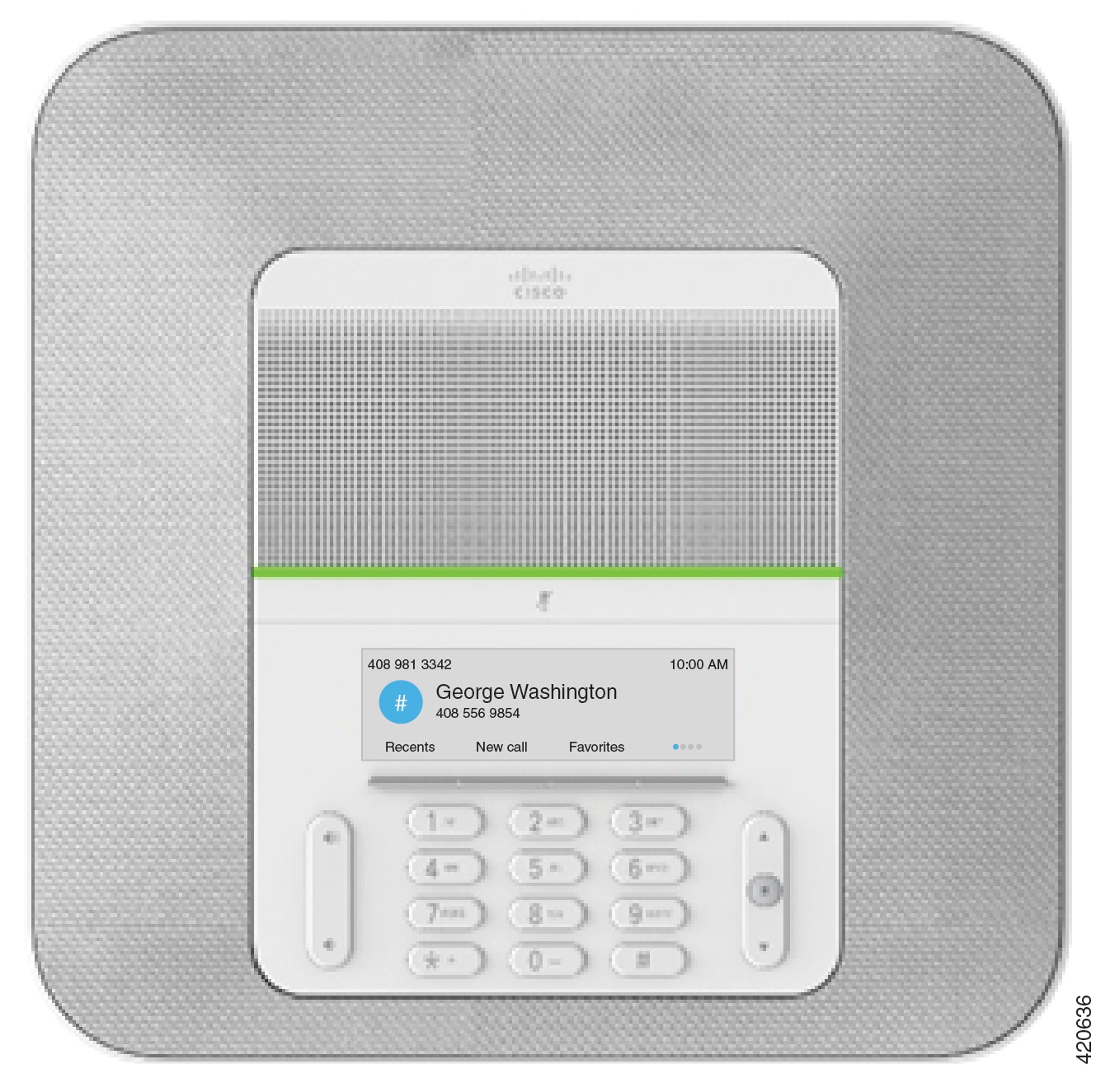
Your Cisco IP Conference Phone 8832 and 8832NR

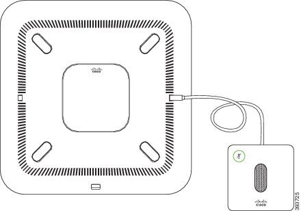
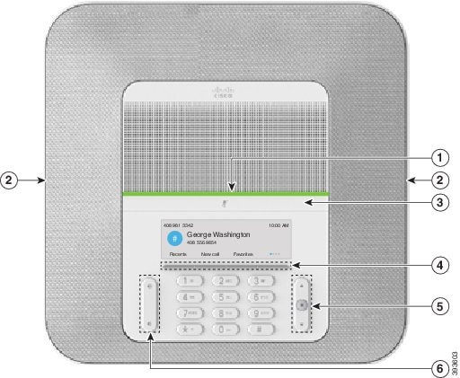
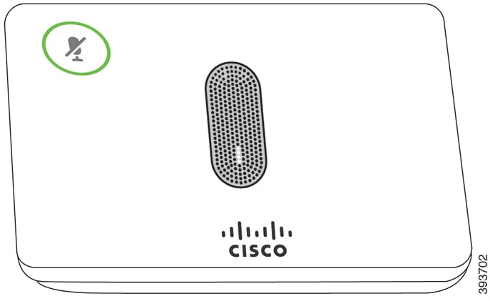
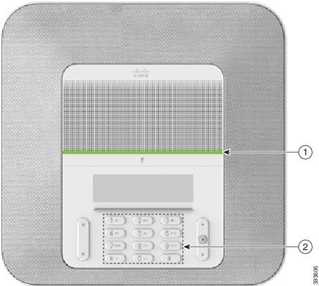
The Cisco IP Conference Phone 8832 and 8832NR provide high‑definition (HD) audio performance and 360-degree coverage for medium to large conference rooms and executive offices. The conference phone has sensitive microphones that let you speak in a normal voice and be clearly heard from up to 10 feet (2.1 m) away.

Figure 1. Cisco IP Conference Phone 8832
Cisco IP Conference Phone 8832

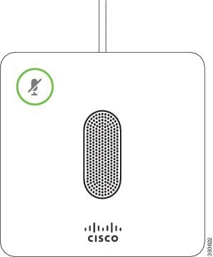
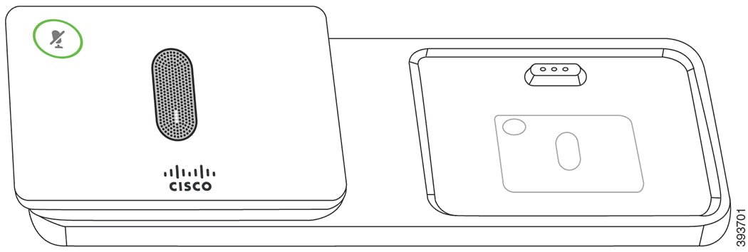
You can connect two wired expansion microphones to the phone to increase coverage in larger conference rooms.

The phone also supports an optional set of two wireless expansion microphones.

The Cisco IP Conference Phone 8832NR (non-radio) version does not support Wi-Fi or wireless expansion microphones.

The phone can be used for a 20 x 20 foot (6.1 x 6.1 m) room and up to 10 people. When you add the expansion microphones, coverage extends to a 20 x 34 foot (6.1 x 10 m) room and up to 22 people.

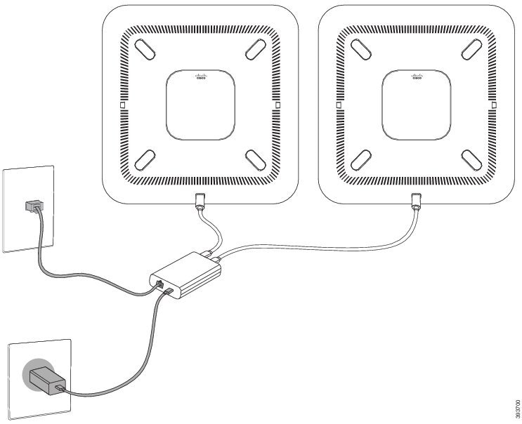
You can connect two base units to increase the coverage for a room. This configuration requires the optional Daisy Chain kit and can support two expansion microphones (either wired or wireless, but not a mixed combination). If you are using wired microphones with the Daisy Chain kit, the configuration provides coverage for a room up to 20 x 50 feet (6.1 x 15.2 m) and up to 38 people. If you are using wireless microphones with the Daisy Chain kit, the configuration provides coverage for a room up to 20 x 57 feet (6.1 x 17.4 m) and up to 42 people.

Feature Support

This document describes all the features that the device supports. However, not all features may be supported with your current configuration. For information on supported features, contact your administrator.

New and Changed Information

You can use the information in the following sections to understand what has changed in the document. Each section contains the major changes.

New and Changed Information for Firmware Release 14.1(1)SR2

The following information is new or changed for Firmware Release 14.1(1).

Feature

New or Changed

Updated the topic to add more information

Compliance Statements for Canada

New and Changed Information for Firmware Release 12.8(1)

Table 2. New and Changed Information for Firmware Release 12.8(1)

Feature

New or Changed Content

Phone Data Migration

Replace Your Existing Phone with a New Phone

New and Changed for Firmware Release 12.7(1)

The following table shows the changes made for Firmware Release 12.7(1).

Table 3. Cisco IP Conference Phone 8832 User Guide Revisions for Firmware Release 12.7(1)

Revision

Updated Section

Updated for hunt group calls on Call Alert

Answer a Call Within Your Hunt Group

General changes

In certain circumstances, users who dialed a number that was busy received the reorder tone. With this release, the user hears the busy tone.

New sections Conference Phone Navigation, Conference Phone Softkeys, Phone Icons, and Clean the Phone Screen.

New and Changed Information for Firmware Release 12.6(1)

No user guide updates were required for Firmware Release 12.6(1).

New and Changed Information for Firmware Release 12.5(1)SR3

The following table shows the changes that were made for Firmware Release 12.5(1)SR3.

Table 4. Cisco IP Conference Phone 8832 User Guide Revisions for Firmware Release 12.5(1)SR3

Revision

New or Updated Section

New topic

Phone Keypad Characters

New and Changed Information for Firmware Release 12.5(1)SR2

No User Guide updates were required for Firmware Release 12.5(1)SR2.

Firmware Release 12.5(1)SR2 replaces Firmware Release 12.5(1) and Firmware 12.5(1)SR1. Firmware Release 12.5(1) and Firmware Release 12.5(1)SR1 have been deferred in favor of Firmware Release 12.5(1)SR2.

New and Changed Information for Firmware Release 12.5(1)SR1

No updates were required for Firmware Release 12.5(1)SR1.

New and Changed Information for Firmware Release 12.5(1)

No updates were required for Firmware Release 12.5(1).

New and Changed Information for Firmware Release 12.1(1)

The following table shows the changes that were made for Firmware Release 12.1(1).

Table 5. Cisco IP Conference Phone 8832 User Guide Revisions for Firmware Release 12.1(1)

Revision

New or Updated Section

Updates to support for Cisco IP Conference Phone 8832 PoE Injector

Connect to the Network

Support for Wireless Microphone

Support for Daisy Chain

Support for Cisco IP Conference Phone 8832 Non-PoE Ethernet Injector

Connect to the Network

Support for Wi-Fi

Support for Mobile and Remote Access Through Expressway

Support for CMC and FAC

Calls That Require a Billing Code or Authorization Code

Phone Setup

Your administrator sets up your phone and connects it to the network. If your phone is not set up and connected, contact your administrator for instructions.

Connect to the Network

You need to connect the phone to the network.

  • Wired network connection—All wired network connections use one of the following:

    • PoE deployment: Connect the phone to the Cisco IP Conference Phone 8832 PoE Injector (CP-8832-POE) and connect the injector to the network with an Ethernet cable.

    • Non-PoE deployment: Connect the phone to the Cisco IP Conference Phone 8832 Non-PoE Ethernet Injector (CP-8832-ETH or CP-8832-ETH-WW). Then, connect the injector to the network with an Ethernet cable and plug the injector into the electric outlet.

  • Wireless connection—The Cisco IP Conference Phone 8832 can connect to a Wireless Access Point using Wi-Fi. This deployment requires the power supply (CP-8832-PWR or CP-8832-PWR-WW).

Mobile and Remote Access Through Expressway—If your administrator sets up Mobile and Remote Access Through Expressway and you connect your phone to the network, it connects to the Expressway server.


Note

CP-8832-ETH and CP-8832-PWR are for North America. CP-8832-ETH-WW and CP-8832-PWR-WW are for other locations.


Figure 2. PoE Deployment

Cisco IP Conference Phone 8832 PoE Injector with PoE power

Figure 3. Non-PoE Deployment

Cisco IP Conference Phone 8832 Non-PoE Ethernet Injector with Ethernet power

Figure 4. Wi-Fi Network Connection
Wi-Fi Network Connection

Set Up Wi-Fi Client

The Cisco IP Conference Phone 8832 can access a Wi-Fi network. You need a power adapter to power the phone. The Cisco IP Conference Phone 8832NR cannot be used with a Wi-Fi network.

Before you begin

Your administrator needs to configure settings on the call control system to enable Wi-Fi access.

Procedure

Step 1

If the phone is plugged into the Ethernet, unplug the Ethernet cable.

Step 2

Press Settings.

Step 3

Navigate to Admin settings > Network setup > Wi-Fi client setup.

Step 4

Navigate to Wireless and press On.

Step 5

Press Apply to save the changes, or press Revert to cancel the changes.

Step 6

Navigate to Network name.

Step 7

When the phone finishes scanning the SSID, choose a network to join.

Step 8

Enter your Wi-Fi credentials and press Connect.


Connect to a Preconfigured Wi-Fi Network

You can connect your Cisco IP Conference Phone 8832 to the network using Wi-Fi, but, for security, enter your username and password. But, the Cisco IP Conference Phone 8832NR does not support Wi-Fi.

Depending upon how your phone is configured, you could be required to sign in when you join a Wi-Fi network or when your phone powers up.

You cannot dismiss the Wi-Fi sign-in window without entering the correct username and password.

Procedure

Step 1

Enter your Wi-Fi credentials when prompted.

Step 2

Select Sign-in.


Connect with Activation Code Onboarding

If your network has been configured to support this feature, then you can use Activation Code Onboarding to connect to your company's phone network.

Enter an Activation Code

Activation codes are used to set up your new phone. They can only be used once, and expire after 1 week. Contact your administrator if you don't know your code or if you need a new one.

Procedure

Step 1

Enter your activation code on the activation screen.

Step 2

Press Submit.


Connect to Expressway

You can use Mobile and Remote Access Through Expressway to connect to your corporate network when you are working away from your office.

Procedure

Step 1

Reset service mode through Settings > Admin Settings > Reset Settings > Service mode.

Step 2

Press Select when prompted to change the service mode.

Step 3

Enter the service domain and press Continue.

Step 4

Enter your username and password.

Step 5

Select Sign in.


Install the Wired Expansion Microphones

The phone supports an optional kit with two wired expansion microphones. You can extend the microphones up to 7 feet (2.13m) from the phone. For best results, place the microphones between 3 feet (0.91 m) and 7 feet (2.1 m) away from the phone.

Procedure


Step 1

Plug the end of the microphone cable into the port on the side of the phone.

Step 2

Extend the microphone cable to the desired position.

The following figure shows installation of a wired expansion microphone.
Figure 5. Wired Expansion Microphone Installation
Wired Expansion Microphone Installation

Install the Wireless Expansion Microphones

The conference phone provides the option of connecting two wireless expansion microphones.

Note

You must use either two wired microphones or two wireless microphones with the phone, but not a mixed combination.


When the phone is in a call, the LED on the expansion microphone is lit green. To mute the expansion microphone, press the Mute key. When the microphone is muted, the LED is lit red. When the battery in the microphone is low, the battery indication LED blinks rapidly.

Before you begin

Disconnect the wired expansion microphones before you install wireless expansion microphones. You cannot use both wired and wireless expansion microphones at the same time.

Procedure


Step 1

Position the table mount plate on the table surface location where you want to place the microphone.

Step 2

Remove the adhesive for the double-stick tape on the bottom of the table mount plate. Place the table mount plate to adhere to the table surface.

Step 3

Attach the microphone to the table mount plate. Magnets are embedded in the microphone to snap the unit into place.

You can move the microphone and attached table mount to a different location on the table surface as needed. Use care when moving to protect the unit.


Pair a Wireless Microphone

Before you begin

Unplug any wired microphones.

Procedure


Step 1

Press Settings.

Step 2

Select Admin Settings > Microphones > Wireless microphones.

Step 3

Select either Microphone 1 or Microphone 2 and press Pair.

If a microphone is already linked to a particular channel, the phone screen shows that the microphone is paired.

Step 4

Press Mute on the wireless microphone until the microphone LED blinks white.

If the pairing succeeds, the phone screen displays a success message.

Step 5

(Optional) Press Cancel to revert to the Wireless microphones menu.


Unpair a Wireless Microphone

Procedure


Step 1

Press Settings.

Step 2

Select Admin Settings > Microphones > Wireless microphones.

Step 3

Select either Microphone 1 or Microphone 2.

If the selected channel is paired, the Unpair softkey displays on the phone screen.

Step 4

Press Unpair.


Install the Wireless Microphone Charging Cradle

You use the charging cradle to charge the wireless microphone battery.

Procedure


Step 1

Plug the charging cradle power adapter into an electrical outlet.

Step 2

Plug one end of the USB-C cable to the charging cradle and the other end into the power adapter.

The following figure shows installation of a wireless microphone charging cradle.
Figure 6. Wireless Microphone Charging Cradle Installation
Wireless Microphone Charging Cradle Installation

Charge a Wireless Microphone

Before you begin

Install the wireless microphone charging cradle. For more information, see Install the Wireless Microphone Charging Cradle.

Procedure


Step 1

Place the microphone in the charging cradle.

Step 2

If the LED on the cradle is not white, remove the microphone and replace it in the cradle.


Daisy Chain Mode

You can connect two conference phones using a Smart Adapter and the USB-C cables that are provided in the daisy chain kit to expand the audio coverage area in a room.

In daisy chain mode, both units receive power though the Smart Adapter which is connected to a power adapter. You can use only one external microphone per unit. You can use either a pair of wired microphones with the units or a pair of wireless microphones with the units, but not a mixed combination of the microphones. When a wired microphone is connected to one of the units, it unpairs any wireless microphones that are connected to the same unit. Whenever there is an active call, the LEDs and the menu options on the phone screen of both units are synchronized.

Install the Conference Phone in Daisy Chain Mode

The daisy chain kit contains a Smart Adapter, a short LAN cable, two long, thicker USB-C cables, and a shorter, thinner USB-C cable. In daisy chain mode, the conference phones require external power from an electrical outlet. You must use the Smart Adapter to connect the phones together. The long USB-C cables go to the phone and the short one goes to the power adapter. Refer to the following figure when you connect the power adapter and the LAN port to the Smart Adapter.

Figure 7. Smart Adapter Power Port and LAN Port

You can use only one microphone per unit.


Note

You must use either two wired microphones or two wireless microphones with the phone, but not a mixed combination.


The USB-C cable for the power adapter is thinner than the USB-C cables that connect to the phone.

Procedure

Step 1

Plug the power adapter into the electrical outlet.

Step 2

Connect the short, thinner USB-C cable from the power adapter to the Smart Adapter.

Figure 8. Smart Adapter USB Port Connected to the Power Outlet
Step 3

Connect the Ethernet cable to the Smart Adapter and the LAN port.

Figure 9. Smart Adapter LAN Port Connected to the LAN Port on the Wall Outlet
Step 4

Connect the first phone to the Smart Adapter using the longer, thicker USB-C cable.

Step 5

Connect the second phone to the Smart Adapter using a USB-C cable.

The following figure shows installation of the conference phone in daisy chain mode.
Figure 10. Conference Phone Installation in Daisy Chain Mode

Replace Your Existing Phone with a New Phone

You can change your phone model. The change can be required for a number of reasons, for example:

  • You have updated your Cisco Unified Communications Manager (Unified CM) to a software version that doesn't support the phone model.

  • You wants a different phone model from their current model.

  • Your phone requires repair or replacement.

Limitation: If the old phone has more lines or line buttons than the new phone, the new phone doesn't have the extra lines or line buttons configured.

The phone reboots when the configuration is complete.

Before you begin

Your administrator needs to set up Cisco Unified Communications Manager to enable the phone migration.

You need a new phone that hasn't been connected to the network or previously configured.

Procedure


Step 1

Power off the old phone.

Step 2

Power on the new phone.

Step 3

If prompted, enter your activation code.

Step 4

Select Replace an existing phone.

Step 5

Enter the primary extension of the old phone.

Step 6

If the old phone had a PIN assigned, enter the PIN.

Step 7

Press Submit.

Step 8

If you have several devices, select the device to replace from the list and press Continue.


Self Care Portal

You can customize some phone settings with the Self Care portal web site, which you access from your computer. The Self Care portal is part of your organization's Cisco Unified Communications Manager.

Your administrator gives you the URL to access the Self Care portal, and provides your user ID and password.

In the Self Care portal, you can control features, line settings, and phone services for your phone.

  • Phone features include speed dial, do not disturb, and your personal address book.

  • Line settings affect a specific phone line (directory number) on your phone. Line settings can include call forwarding, visual and audio message indicators, ring patterns, and other line-specific settings.

  • Phone services can include special phone features, network data, and web-based information (such as stock quotes and movie listings). Use the Self Care Portal to subscribe to a phone service before you access it on your phone.

The following table describes some specific features that you configure with the Self Care portal. For more information, see the Self Care portal documentation for your call control system.

Table 6. Features Available on the Self Care Portal

Features

Description

Call forward

Use the number that receives calls when call forward is enabled on the phone. Use the Self Care portal to set up more complicated call forward functions, for example, when your line is busy.

Additional phones

Specify the additional phones such as your mobile phone that you want to use to make and receive calls with the same directory numbers as your desk phone. You can also define blocked and preferred contacts to restrict or allow calls from certain numbers to be sent to your mobile phone. When you set up additional phones, you can also set up these features:

  • Single number reach—Specify whether the additional phone should ring when someone calls your desk phone.

  • Mobile calls—If the additional phone is a mobile phone, you can set it up to allow you to transfer mobile calls to your desk phone or desk phone calls to your mobile phone.

Speed dial

Assign phone numbers to speed-dial numbers so that you can quickly call that person.

Speed-Dial Numbers

When you dial a number on your phone, you enter a series of digits. When you set up a speed-dial number, the speed-dial number must contain all the digits you need to make the call. For example, if you need to dial 9 to get an outside line, you enter the number 9 and then the number you want to dial.

You can also add other dialed digits to the number. Examples of additional digits include a meeting access code, an extension, a voicemail password, an authorization code, and a billing code.

The dial string can contain the following characters:

  • 0 to 9

  • Pound (#)

  • Asterisk (*)

  • Comma (,)—This is the pause character, and gives a 2 second delay in the dialing. You can have several commas in a row. For example, two commas (,,) represent a pause of 4 seconds.

The rules for dial strings are:

  • Use the comma to separate the parts of the dial string.

  • An authorization code must always precede a billing code in the speed-dial string.

  • A single comma is required between the authorization code and the billing code in the string.

  • A speed-dial label is required for speed dials with authorization codes and additional digits.

Before you configure the speed dial, try to dial the digits manually at least once to ensure that the digit sequence is correct.

Your phone does not save the authorization code, billing code, or extra digits from the speed dial in the call history. If you press Redial after you connect to a speed-dial destination, the phone prompts you to enter any required authorization code, billing code, or additional digits manually.

Example

To set up a speed-dial number to call a person at a specific extension, and if you need an authorization code and billing code, consider the following requirements:

  • You need to dial 9 for an outside line.

  • You want to call 5556543.

  • You need to input the authorization code 1234.

  • You need to input the billing code 9876.

  • You must wait for 4 seconds.

  • After the call connects, you must dial the extension 56789#.

In this scenario, the speed-dial number is 95556543,1234,9876,,56789#.

Cisco IP Conference Phone 8832 Buttons and Hardware

The following figure shows the Cisco IP Conference Phone 8832.

Figure 11. Cisco IP Conference Phone 8832 Buttons and Features
Cisco IP Conference Phone 8832 Buttons and Features

The following table describes the buttons on the Cisco IP Conference Phone 8832.

Table 7. Cisco IP Conference Phone 8832 Buttons

1

LED bar

Indicates call states:

  • Green, solid—Active call

  • Green, flashing—Incoming call

  • Green, pulsing—Held call

  • Red, solid—Muted call

2

Expansion microphone port

The wired expansion microphone cable plugs into the port.

3

Mute bar

Mute key Toggles the microphone on or off. When you mute the microphone, the LED bar lights red.

4

Softkey buttons

Mute key Access functions and services.

5

Navigation bar and Select button

Mute key Scroll through menus, highlight items, and select the highlighted item.

6

Volume button

Mute key Adjusts the speakerphone volume (off hook) and the ringer volume (on hook).

When you change the volume, the LED bar lights white to show the volume change.

Conference Phone Navigation

Use the Navigation bar to scroll through menus. Use the inner Select button of the Navigation bar to select menu items.

If a menu item has an index number, you can enter the index number with the keypad to select the item.

Conference Phone Softkeys

You can interact with the features on your phone with the softkeys. Softkeys, located below the screen, give you access to the function displayed on the screen above the softkey. The softkeys change depending on what you are doing at the time.

The and softkeys indicate more softkey functions are available.

Phone Icons

Your phone screen displays many icons. This section gives images of the common icons

Icons are in color or grayscale, depending on the screen.

Recents

Icon

Description

handset with left arrow

Incoming call

handset with right arrow

Outgoing call

handset with left arrow over the top

Missed call

Wi-Fi Network Icons

If your phone is connected to the Wi-Fi network, you see these icons.

Table 8. Network Icons

Icon

Description

wi-fi icon with 4 active bars

wi-fi icon with 3 active bars

wi-fi icon with 2 active bars

wi-fi icon with 1 active bar

Wi-Fi connected and the number of bars indicates the signal strength.

wi-fi icon with no active bars

There is no Wi-Fi connection

Phone Keypad Characters

The phone keypad allows you to enter letters, numbers, and special characters. You press the Two (2) to Nine (9) keys to get the letters and numbers. You use the One (1), Zero (0)), Asterisk (*), and Pound (#) keys for special characters. The following table lists the special characters for each key for the English locale. Other locales will have their own characters.

Table 9. Special Characters on the Keypad

Keypad Key

Special Characters

One (1)

/ . @ : ; = ? -_ & %

Zero (0)

(space) , ! ^ ' " |

Asterisk (*)

+ * ~ ` < >

Pound (#)

# $ £ ◻ \ ( ) { } [ ]

Clean the Phone Screen

Procedure


If your phone screen gets dirty, wipe it with a soft, dry cloth.

Caution 

Do not use any liquids or powders on the phone because they can contaminate the phone components and cause failures.


Wired Expansion Microphone

The Cisco IP Conference Phone 8832 supports two wired expansion microphones, available in an optional kit. Use the expansion microphones in larger rooms or in a crowded room. For best results, we recommend that you place the microphones between 3 feet (0.91 m) and 7 feet (2.1 m) away from the phone.

Figure 12. Wired Expansion Microphone
Wired Expansion Microphone

When you're in a call, the expansion microphone LED around the Mute button is green.

When you mute the microphone, the LED is red. When you press the Mute button, the phone and the expansion microphones are muted.

Wireless Expansion Microphone

The Cisco IP Conference Phone 8832 supports two expansion wireless microphones, available with a charging cradle in an optional kit. When the wireless microphone is placed on the charging cradle for charging, the LED on the cradle is lit white.

Figure 13. Wireless Microphone
Wireless Microphone
Figure 14. Wireless Microphone Mounted on the Charging Cradle
Wireless Microphone Mounted on the Charging Cradle

When the conference phone is in a call, the expansion microphone LED around the Mute button is lit green.

When the microphone is muted, the LED is lit red. When you press the Mute button, the phone and the expansion microphones are muted.

If the phone is paired with a wireless microphone (for example, Wireless microphone 1) and you connect the wireless microphone to a charger, pressing the Show detail softkey indicates the charge level for that microphone.

When the phone is paired with a wireless microphone and you connect a wired microphone, the wireless microphone gets unpaired and the phone is paired with the wired microphone. A notification appears on the phone screen indicating that the wired microphone is connected.

Phone Firmware and Upgrades

Your phone comes pre-installed with firmware that is specific to the call control system.

Occasionally, your administrator upgrades the phone firmware for you. This upgrade happens in the background even if you are using your phone.

Postpone a Phone Upgrade

When new firmware is available, the Ready to upgrade window is displayed on your phone and a timer begins a 15-second countdown. If you do nothing, the upgrade proceeds.

You can postpone your firmware upgrade for 1 hour and up to 11 times. The upgrade is also postponed if you make or receive a phone call.

Procedure


Select Delay to postpone a phone upgrade.


View the Progress of a Phone Firmware Upgrade

During a phone firmware upgrade, you can view the upgrade progress.

Procedure


Step 1

Press Applications .

Step 2

Press Settings.

Step 3

Select Phone information > Show detail.

Step 4

Select System information , and press Show details.

Step 5

Press Exit.


Energy Savings

Your administrator can reduce the amount of power your phone screen uses with the following options:

  • Power Save—The backlight or screen turns off when the phone is inactive for a set interval.

  • Power Save Plus—Your phone screen turns on and off at times that are based on your work schedule. If your work hours or work days change, you can contact your administrator to reconfigure your phone.

For example, your administrator can set your phone to alert you 10 minutes before it turns off. You see the Select button light up and you get a message that your phone is turning off soon. You get notifications at these intervals:

For example, your administrator can set your phone to alert you 10 minutes before it turns off. You get a message that your phone is turning off soon and you get notifications at these intervals:

  • Four rings at 10 minutes before power off

  • Four rings at 7 minutes before power off

  • Four rings at 4 minutes before power off

  • 15 rings at 30 seconds before power off

If your phone is active, it waits until it has been inactive for a set interval before it notifies you of the pending power shutdown.

Turn On Your Phone

When your phone turns off to save energy, the phone screen is blank and the Select button lights up.

Procedure


Press Select to turn your phone back on.


Additional Help and Information

If you have questions about the functions available on your phone, contact your administrator.

The Cisco website (https://www.cisco.com) contains more information about the phones and call control systems.

Accessibility Features

The Cisco IP Conference Phone 8832 provides accessibility features for the blind, and for the visually, hearing, and mobility impaired. Because many of these features are standard, users with disabilities can access them without any special configuration.

In this document, the term phone support pages refers to the web pages that users can access to set up certain features. For Cisco Unified Communications Manager (Release 10.0 and later), these pages are the Self Care Portal. For Cisco Unified Communications Manager (Release 9.1 and earlier), these pages are the User Options web pages.

For additional information, see the phone User Guide, located here: http://www.cisco.com/c/en/us/support/collaboration-endpoints/unified-ip-phone-8800-series/products-user-guide-list.html

Cisco is committed to designing and delivering accessible products and technologies to meet the needs of your organization. You can find more information about Cisco and its commitment to accessibility at this URL: https://www.cisco.com/go/accessibility

Hearing-Impaired Accessibility Features

Your conference phone comes with standard accessibility features that require little or no setup.

Figure 15. Hearing-Impaired Accessibility Features
Hearing-Impaired Accessibility Features

The following table describes the hearing-impaired accessibility features on the Cisco IP Conference Phone 8832.

Table 10. Hearing-Impaired Accessibility Features

Item

Accessibility Feature

Description

1

LED bar

The phone screen displays the current state and the LED bar displays:

  • Green, solid—Active call

  • Green, flashing—Incoming call

  • Green, pulsing—Held call

  • Red, solid—Muted call

2

Visual notification of phone state and message-waiting indicator

The phone screen displays the current state.

When you have a message, a message is displayed on the phone screen. Your phone also provides an audible message-waiting indicator.

To change the audible voice-message indicator, sign in to the Self Care portal and access the message-indicator settings. You can change each setting to on or off.

Your administrator can also change your settings.

3

Adjustable ringtone, pitch, and volume

  • Select Settings > Preferences to change the ringtone.

  • Adjust the volume level for the phone ring. When not in a call, press Volume to raise or lower the volume.

    When you adjust the volume, the LED bar lights white to show the volume increase or decrease.

Your administrator can also change your settings.

Vision-Impaired and Blind Accessibility Features

Your phone comes with standard accessibility features that require little or no setup.

Figure 16. Vision-Impaired and Blind Accessibility Features
Vision-Impaired and Blind Accessibility Features

The following table describes the vision-impaired and blind accessibility features on the Cisco IP Conference Phone 8832.

Table 11. Vision-Impaired and Blind Accessibility Features

Item

Accessibility Feature

Description

1

High-contrast visual and audible alert of incoming call with the LED bar

  • The LED bar is located above the Mute button and the screen.

Use the Mute button to toggle the microphone on or off. When the microphone is muted, the LED bar lights red. When you turn on Mute, your phone beeps once; when you turn off Mute, your phone beeps twice.

2

Mute button

  • This button is located between the LED bar and the screen.

Alerts you to an incoming call. The LED flashes during incoming calls.

Colors indicate your phone's status:

  • Green, solid—Active call

  • Green, flashing—Incoming call

  • Green, pulsing—Held call

  • Red, solid—Muted call

3

Softkeys

  • These are buttons just below the LCD.

Provide access to special functions. The LCD displays the functions.

4

Navigation cluster (includes the Navigation bar and the Select button)

  • The Navigation cluster is located to the right of the keypad.

Use the Navigation bar to move up and down in the phone LCD. The Select button is in the center of the Navigation bar.

5

Standard 12-key layout

Allows you to use existing or familiar key positions. Key 5 has a nib.

6

Volume key

  • This key is located to the left of the keypad.

Allows you to increase or decrease the ring volume or the sound.

Press up on the rocker key to increase the volume. Press down on the rocker key to decrease the volume.

When you adjust the volume, the LED bar lights white to show the volume increase or decrease.

Mobility-Impaired Accessibility Features

Your conference phone comes with standard accessibility features that require little or no setup.

Figure 17. Mobility-Impaired Accessibility Features
Mobility-Impaired Accessibility Features

The following table describes the mobility-impaired accessibility features on the Cisco IP Conference Phone 8832.

Table 12. Mobility-Impaired Accessibility Features

Item

Accessibility Feature

Description

1

LED bar

Indicates your phone's status:

  • Green, solid—Active call

  • Green, flashing—Incoming call

  • Green, pulsing—Held call

  • Red, solid—Muted call

2

Tactile-discernible buttons and functions, including a nib on Key 5

Allow you to easily locate your phone's keys. For example, Key 5 has a nib, which you can use to locate other key positions.

Third-Party Accessibility Applications

Cisco works closely with partners to provide solutions that complement the accessibility and usability of Cisco products and solutions. There are third-party applications such as real-time captioning on Cisco IP Phones, Text Telephones for the Deaf (TDD/TTY), Real Time Text (RTT), hearing/voice carry over (HCO/VCO), audible caller ID, inline amplifiers for handsets for louder call sound, "busy lights", audio/visual emergency notifications through Cisco IP Phones (supporting users with disabilities), etc.

For more information about third-party applications, contact your administrator.

Troubleshooting

You may experience issues related to the following scenarios:

  • Your phone cannot communicate with the call control system.

  • The call control system has communication or internal problems.

  • Your phone has internal problems.

If you experience problems, your administrator can help troubleshoot the root cause of the problem.

Find Information About Your Phone

Your administrator may ask for information about your phone. This information uniquely identifies the phone for troubleshooting purposes.

Procedure

Step 1

Select System information.

Step 2

Press Exit.


Report Call Quality Issues

Your administrator may temporarily configure your phone with the Quality Reporting Tool (QRT) to troubleshoot performance problems. Depending on the configuration, use the QRT to:

  • Immediately report an audio problem on a current call.

  • Select a general problem from a list of categories and choose reason codes.

Procedure

Step 1

Press Report quality.

Step 2

Scroll and select the item that closely matches your problem.

Step 3

Press the Select softkey to send the information to your system administrator.


Report All Phone Issues

You can use the Cisco Collaboration Problem Report Tool (PRT) to collect and send phone logs, and to report problems to your administrator. If you see a message that the PRT upload has failed, the problem report is saved on the phone and you should alert your administrator.

Procedure

Step 1

Press Applications .

Step 2

Select Settings > System information > Report problem.

Step 3

Enter the date and time that you experienced the problem in the Date of problem and Time of problem fields.

Step 4

Select Problem description.

Step 5

Select a description from the displayed list, then press Submit.


Lost Phone Connectivity

Sometimes your phone loses its connection to the phone network. When this connection is lost, your phone displays a message.

If you are on an active call when the connection is lost, the call continues. But, you don't have access to all normal phone features because some functions require information from the call control system. For example, your softkeys might not work as you expect.

When the phone reconnects to the call control system, you'll be able to use your phone normally again.

Cisco One-Year Limited Hardware Warranty Terms

Special terms apply to your hardware warranty and services that you can use during the warranty period.

Your formal Warranty Statement, including the warranties and license agreements applicable to Cisco software, is available at: Product Warranties.