Cisco BTS 10200 Softswitch H.323 Guide, Release 6.0.4
Bias-Free Language
The documentation set for this product strives to use bias-free language. For the purposes of this documentation set, bias-free is defined as language that does not imply discrimination based on age, disability, gender, racial identity, ethnic identity, sexual orientation, socioeconomic status, and intersectionality. Exceptions may be present in the documentation due to language that is hardcoded in the user interfaces of the product software, language used based on RFP documentation, or language that is used by a referenced third-party product. Learn more about how Cisco is using Inclusive Language.
- Updated:
- May 13, 2012
Chapter: Chapter 3 - Configuring
- Provision H.323-Based TGs, Logical GWs, and GKs
- Provision H.323-Based Video Phone Terminals and Subscribers
- Provision H.323-Based Outbound Routing Data
Configuring
This chapter explains how to perform the following tasks:
•![]() Provision H.323-Based TGs, Logical GWs, and GKs
Provision H.323-Based TGs, Logical GWs, and GKs
•![]() Provision H.323-Based Video Phone Terminals and Subscribers
Provision H.323-Based Video Phone Terminals and Subscribers
•![]() Provision H.323-Based Outbound Routing Data
Provision H.323-Based Outbound Routing Data
•![]() Provision H.323-Based Inbound Routing
Provision H.323-Based Inbound Routing
•![]() Provision ANI Screening and Routing
Provision ANI Screening and Routing
•![]() Provision for Interoperability with Cisco CallManager
Provision for Interoperability with Cisco CallManager
•![]() Provision Annex E Functionality
Provision Annex E Functionality
•![]() Provision Additional H.323 Options
Provision Additional H.323 Options
To see a complete set of commands, see the "Example of Provisioning Script" section.

Note ![]() The tasks described in this section include examples of CLI commands that illustrate how to provision specific features. Most of the database tables in the Cisco BTS 10200 Softswitch have additional tokens that are not used in these examples. For a complete CLI information, see the Cisco BTS 10200 Softswitch CLI Database.
The tasks described in this section include examples of CLI commands that illustrate how to provision specific features. Most of the database tables in the Cisco BTS 10200 Softswitch have additional tokens that are not used in these examples. For a complete CLI information, see the Cisco BTS 10200 Softswitch CLI Database.
Note ![]() The command sequences shown in this section provide guidance on how to provision a new system. Therefore, in most cases the commands are "add" commands. If you are modifying previously-provisioned GWs, TGs, and so forth, use the "change" commands.
The command sequences shown in this section provide guidance on how to provision a new system. Therefore, in most cases the commands are "add" commands. If you are modifying previously-provisioned GWs, TGs, and so forth, use the "change" commands.
Provision H.323-Based TGs, Logical GWs, and GKs
The commands in this section provision the following entities on the Cisco BTS 10200 Softswitch:
•![]() H.323-based TGs.
H.323-based TGs.
•![]() H.323-based logical GWs internal to the Cisco BTS 10200 Softswitch (the Cisco BTS 10200 Softswitch provides a maximum of four H.323-based GWs).
H.323-based logical GWs internal to the Cisco BTS 10200 Softswitch (the Cisco BTS 10200 Softswitch provides a maximum of four H.323-based GWs).
•![]() Connections to an H.323 GK, if GKs are present in the network.
Connections to an H.323 GK, if GKs are present in the network.
H.323-Based Logical GWs Internal to the Cisco BTS 10200 Softswitch
Each of the H.323-based internal GWs supports trunks, lines, routing options, and communications with external H.323 endpoints. Each GW can communicate with a GK, if one is present in the network. The parameters described in this section support these functions.
Prerequisites
The Cisco BTS 10200 Softswitch database should already be populated with basic provisioning options as described in theCisco BTS 10200 Softswitch Provisioning Guide, Release 6.0.4.
SUMMARY STEPS
1. ![]() add h323-tg-profile
add h323-tg-profile
2. ![]() add trunk-grp
add trunk-grp
3. ![]() add qos
add qos
4. ![]() add h323-gw
add h323-gw
5. ![]() add h323-gw2gk
add h323-gw2gk
6. ![]() change trunk-grp
change trunk-grp
Note ![]() We recommend that you assign a specific type of inbound routing to each of the four H.323 GWs according to your network requirements. For example, assign tsap-addr routing on one GW, gw-id routing on one GW, "none" on one GW, and choose the routing type for the fourth GW according to your network design. Selecting "none" results in the most efficient processing, but it reduces flexibility.
We recommend that you assign a specific type of inbound routing to each of the four H.323 GWs according to your network requirements. For example, assign tsap-addr routing on one GW, gw-id routing on one GW, "none" on one GW, and choose the routing type for the fourth GW according to your network design. Selecting "none" results in the most efficient processing, but it reduces flexibility.
DETAILED STEPS
Provision H.323-Based Video Phone Terminals and Subscribers
The Cisco BTS 10200 Softswitch can be configured as up to four internal H.323-based logical GWs. Each of these GWs can support direct communications with external H.323 endpoints. Each GW can communicate with a GK, if one is present in the network. The commands in this section provision the subscriber lines for H.323-based video phone terminals and subscribers.
Prerequisites
The Cisco BTS 10200 Softswitch database should already be populated with basic provisioning options as described in the Cisco BTS 10200 Softswitch Provisioning Guide, Release 6.0.4.
SUMMARY STEPS
1. ![]() add h323-term-profile
add h323-term-profile
2. ![]() add h323-term
add h323-term
3. ![]() add subscriber-profile
add subscriber-profile
4. ![]() add subscriber
add subscriber
5. ![]() add qos
add qos
DETAILED STEPS
Provision H.323-Based Outbound Routing Data
This section explains how to provision H.323-based routing data for outbound calls on the Cisco BTS 10200 Softswitch. The Cisco BTS 10200 Softswitch supports sending of either the H.323/H.225 sourceCircuitID or destinationCircuitID parameter (or both) for the outbound call leg.
This section covers the following topics:
•![]() Understanding the Outbound Routing Process
Understanding the Outbound Routing Process
•![]() Outbound Routing Option Summary
Outbound Routing Option Summary
•![]() H.323 Tandem Calls with Circuit Information Sent
H.323 Tandem Calls with Circuit Information Sent
•![]() SS7-originated Calls Retransmitted as Outbound H.323 Calls with Circuit Information
SS7-originated Calls Retransmitted as Outbound H.323 Calls with Circuit Information
Understanding the Outbound Routing Process
Outbound routing is managed through a four-step process that starts when an H.323-based call is originated or received on the Cisco BTS 10200 Softswitch:
1. ![]() The system examines the originating/incoming H.225 call data (H.323 ARQ/SETUP message).
The system examines the originating/incoming H.225 call data (H.323 ARQ/SETUP message).
2. ![]() The system examines the provisioned values of certain parameters in the internal database and prepares routing data that can be sent for the outbound call leg.
The system examines the provisioned values of certain parameters in the internal database and prepares routing data that can be sent for the outbound call leg.
3. ![]() The system examines the provisioned values of certain parameters in the internal database to determine whether to transmit a sourceCircuitID, a destinationCircuitID, neither, or both, in the H.225 call data (ARQ/SETUP message) for the outbound leg.
The system examines the provisioned values of certain parameters in the internal database to determine whether to transmit a sourceCircuitID, a destinationCircuitID, neither, or both, in the H.225 call data (ARQ/SETUP message) for the outbound leg.
4. ![]() If provisioned to send, the system transmits the applicable source and/or destination carrier IDs in the outbound ARQ/SETUP message.
If provisioned to send, the system transmits the applicable source and/or destination carrier IDs in the outbound ARQ/SETUP message.

Tip ![]() The settings in item 3. (above) take precedence over the first two steps: If the parameters in 3. are set to N (no), the system does not transmit this circuit information, regardless of the data or settings described in items 1. and 2.
The settings in item 3. (above) take precedence over the first two steps: If the parameters in 3. are set to N (no), the system does not transmit this circuit information, regardless of the data or settings described in items 1. and 2.
Table 3-1 describes several routing terms used in this section, and indicates the relationship of network terminology, H.225-message terminology, and the tokens used to control this data in the Cisco BTS 10200 Softswitch.
Outbound Routing Option Summary
Table 3-2 summarizes the outbound routing data options. It shows how the provisioned values affect the outbound routing data sent by the system.
Note ![]() If no value is shown (—), the provisioning of the specified table has no effect in this scenario.
If no value is shown (—), the provisioning of the specified table has no effect in this scenario.
|
|
Data Sent |
or Outbound TRUNK-GRP Table |
|
|
|---|---|---|---|---|
— |
Set both |
— |
||
sourceCircuitID Based on TRUNK-SUB-GROUP in the Terminating TRUNK-GRP Table |
Provision a value for TRUNK-SUB-GROUP in the terminating TG table. |
Set SEND-SRC-CIRCUIT-ID to Y (yes) in the H323-TG-PROFILE table. |
— |
|
H.323 Tandem Calls with Circuit Information Sent |
Do not provision a value for SP-ID in the outbound TRUNK-GRP table. |
Set SEND-DEST-CIRCUIT-ID to Y (yes). |
Set SP-BASED-ROUTING to N (no). |
|
destinationCircuitID Based on SP-ID in Outbound TRUNK-GRP Table |
Provision a value for SP-ID in the outbound TRUNK-GRP table. |
Set SEND-DEST-CIRCUIT-ID to Y (yes). |
Set SP-BASED-ROUTING to N (no). |
|
sourceCircuitID and destination CircuitID Based on Incoming SETUP Message |
— |
Set SEND-SRC-CIRCUIT-ID to Y (yes). |
Set SP-BASED-ROUTING to Y (yes). |
|
SS7-originated Calls Retransmitted as Outbound H.323 Calls with Circuit Information |
sourceCircuitID Based on TNS/CIP Data Received on the Incoming SS7 Circuit |
— |
Set SEND-SRC-CIRCUIT-ID to Y (yes). |
— |
sourceCircuitID Overwritten by Value of TRUNK-SUB-GROUP in the Terminating TRUNK-GRP Table |
Provision a value for TRUNK-SUB-GROUP in the terminating TG table. |
Set SEND-SRC-CIRCUIT-ID to Y (yes). |
— |
Outbound H.323 Calls
The following routing data options can be provisioned for outbound H.323 calls.
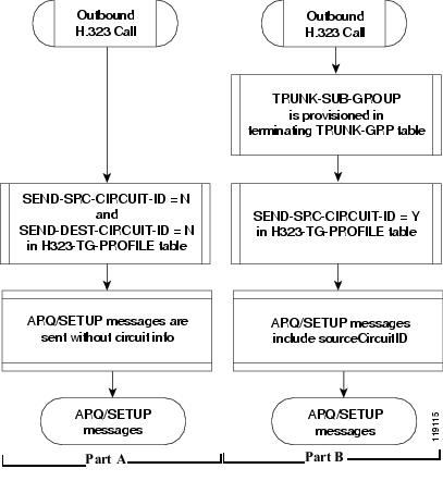
No Circuit Info Sent in ARQ/SETUP Messages
Take the following action to ensure that no circuit info is sent in the outbound ARQ/SETUP messages: Set both SEND-SRC-CIRCUIT-ID and SEND-DEST-CIRCUIT-ID to N in the H323-TG-PROFILE table. See Figure 3-1, Part A.
Note ![]() When you set these parameters to N, the system does not transmit this circuit information, regardless of the data received on the originating or incoming call and the settings in other tables.
When you set these parameters to N, the system does not transmit this circuit information, regardless of the data received on the originating or incoming call and the settings in other tables.
sourceCircuitID Based on TRUNK-SUB-GROUP in the Terminating TRUNK-GRP Table
Take the following action to send sourceCircuitID in the ARQ/SETUP message based on the provisioned TRUNK-SUB-GROUP in the terminating TG table:
•![]() Provision a value for TRUNK-SUB-GROUP in the terminating TG table.
Provision a value for TRUNK-SUB-GROUP in the terminating TG table.
•![]() Set SEND-SRC-CIRCUIT-ID to Y (yes) in the H323-TG-PROFILE table.
Set SEND-SRC-CIRCUIT-ID to Y (yes) in the H323-TG-PROFILE table.
See Figure 3-1, Part B.
Figure 3-1 Circuit-Info Options for Outbound H.323 Calls
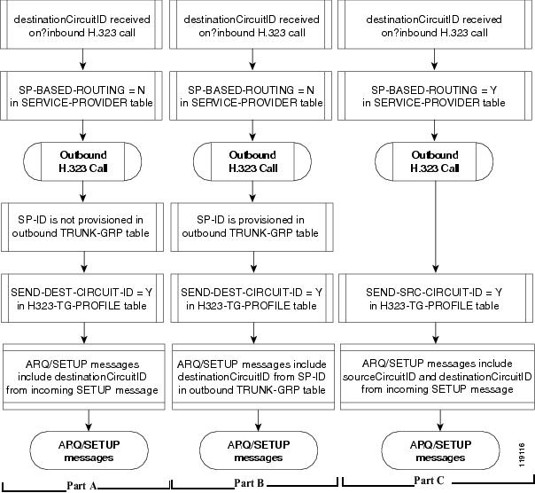
H.323 Tandem Calls with Circuit Information Sent
The following routing data options can be provisioned for outbound H.323 Tandem calls.
destinationCircuitID Based on Incoming SETUP Message
Take the following action to send destinationCircuitID in the ARQ/SETUP message based on the destinationCircuitID contained in the incoming SETUP message:
•![]() Set SP-BASED-ROUTING to N in the SERVICE-PROVIDER table
Set SP-BASED-ROUTING to N in the SERVICE-PROVIDER table
•![]() Do not provision a value for SP-ID in the outbound TRUNK-GRP table
Do not provision a value for SP-ID in the outbound TRUNK-GRP table
•![]() Set SEND-DEST-CIRCUIT-ID to Y in the H323-TG-PROFILE table
Set SEND-DEST-CIRCUIT-ID to Y in the H323-TG-PROFILE table
See Figure 3-2, Part A.
destinationCircuitID Based on SP-ID in Outbound TRUNK-GRP Table
Take the following action to send destinationCircuitID in the ARQ/SETUP message based on the value provisioned for the SP-ID in the outbound TRUNK-GRP table:
•![]() Set SP-BASED-ROUTING to N in the SERVICE-PROVIDER table
Set SP-BASED-ROUTING to N in the SERVICE-PROVIDER table
•![]() Provision a value for SP-ID in the outbound TRUNK-GRP table
Provision a value for SP-ID in the outbound TRUNK-GRP table
•![]() Set SEND-DEST-CIRCUIT-ID to Y in the H323-TG-PROFILE table
Set SEND-DEST-CIRCUIT-ID to Y in the H323-TG-PROFILE table
See Figure 3-2, Part B.
sourceCircuitID and destination CircuitID Based on Incoming SETUP Message
Take the following action to send sourceCircuitID in the ARQ/SETUP message based on the destinationCircuitID contained in the incoming SETUP message:
•![]() Set SP-BASED-ROUTING to Y in the SERVICE-PROVIDER table
Set SP-BASED-ROUTING to Y in the SERVICE-PROVIDER table
•![]() set SEND-SRC-CIRCUIT-ID to Y in the H323-TG-PROFILE table
set SEND-SRC-CIRCUIT-ID to Y in the H323-TG-PROFILE table
See Figure 3-2, Part C.
Figure 3-2 H.323 Tandem Calls with Circuit Information Sent
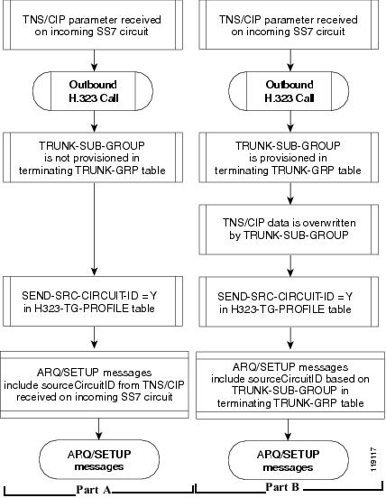
SS7-originated Calls Retransmitted as Outbound H.323 Calls with Circuit Information
The following routing data options can be provisioned for SS7-originated calls that are retransmitted as outbound H.323 calls.
sourceCircuitID Based on TNS/CIP Data Received on the Incoming SS7 Circuit
Take the following action to send sourceCircuitID in the ARQ/SETUP message based on the TNS/CIP data received on the incoming SS7 circuit: Set SEND-SRC-CIRCUIT-ID to Y in the H323-TG-PROFILE table.
See Figure 3-3, Part A.
sourceCircuitID Overwritten by Value of TRUNK-SUB-GROUP in the Terminating TRUNK-GRP Table
Take the following action to send sourceCircuitID in the ARQ/SETUP message based on the provisioned TRUNK-SUB-GROUP in the terminating TG table. (The received TNS/CIP data is overwritten by the value provisioned for TRUNK-SUB-GROUP.)
•![]() Provision a value for TRUNK-SUB-GROUP in the terminating TG table.
Provision a value for TRUNK-SUB-GROUP in the terminating TG table.
•![]() Set SEND-SRC-CIRCUIT-ID to Y in the H323-TG-PROFILE table.
Set SEND-SRC-CIRCUIT-ID to Y in the H323-TG-PROFILE table.
See Figure 3-3, Part B.
Figure 3-3 SS7-originated Calls Retransmitted as Outbound H.323 Calls with Circuit Information
SUMMARY STEPS
1. ![]() add h323-tg-profile
add h323-tg-profile
2. ![]() add trunk-grp
add trunk-grp
DETAILED STEPS
|
|
|
|
|---|---|---|
Step 1 |
ADD H323-TG-PROFILE SEND-SRC-CIRCUIT-ID=<Y|N>
CLI> ADD H323-TG-PROFILE ID=TRUNK_PROFILE_1; SEND-DEST-CIRCUIT-ID=Y; SEND-SRC-CIRCUIT-ID=N; |
The SEND-DEST-CIRCUIT and SEND-SRC-CIRCUIT flags can be set to Y to send the circuit info parameters in the outgoing ARQ/SETUP messages. |
Step 2 |
ADD TRUNK-GRP ID=<TG ID>;
CALL-AGENT-ID=<CA ID>;
TG-TYPE=H323;
TG-PROFILE-ID=<TG PROFILE ID>;
H323-GW-ID=<H.323 GW ID>;
DIAL-PLAN-ID=<DIAL PLAN ID>;
ANI-BASED-ROUTING=N;
SOFTSW-TSAP-ADDR=<DOMAIN NAME OR IP:PORT>;
QOS-ID=<QOS ID>;
SP-ID=<SERVICE PROVIDER ID>;
TRUNK-SUB-GRP=<TRUNK SUBGROUP ID>;
ADD TRUNK-GRP ID=318; CALL-AGENT-ID=CA146; TG-TYPE=H323; TG-PROFILE-ID=TG_PROFILE_1; H323-GW-ID=H323_GW1; DIAL-PLAN-ID=DP001; ANI-BASED-ROUTING=N; SOFTSW-TSAP-ADDR=10.89.227.114:1720; QOS-ID=Codec_1; SP-ID=SP_7777; TRUNK-SUB-GRP=SUBGRP_300; |
Matches incoming H.323 calls on a specific IP:port to a specific TG. It also disables automatic number identification (ANI)-based routing. SP-ID identifies a specific service provider when multiple service providers are provisioned on a single logical CA. TRUNK-SUB-GRP identifies a specific trunk group when multiple trunk groups exist between a Cisco BTS 10200 Softswitch and another softswitch. |
Provision H.323-Based Inbound Routing
This section explains how to provision H.323-based inbound routing options on the Cisco BTS 10200 Softswitch. All incoming calls from the H.323 network are terminated by one of the four H.323 GW instances on the Cisco BTS 10200 Softswitch. Incoming calls can be routed to the Cisco BTS 10200 Softswitch with or without the use of a GK:
•![]() When no RAS signaling to the GK is used, calls are routed directly from the far-end H.323 device.
When no RAS signaling to the GK is used, calls are routed directly from the far-end H.323 device.
•![]() When there is RAS signaling to a GK, calls are routed by the GK toward the Cisco BTS 10200 Softswitch.
When there is RAS signaling to a GK, calls are routed by the GK toward the Cisco BTS 10200 Softswitch.
Figure 3-4 provides an overview of the H.323 inbound routing process.
Figure 3-4 Overview of H.323 Inbound Routing Process
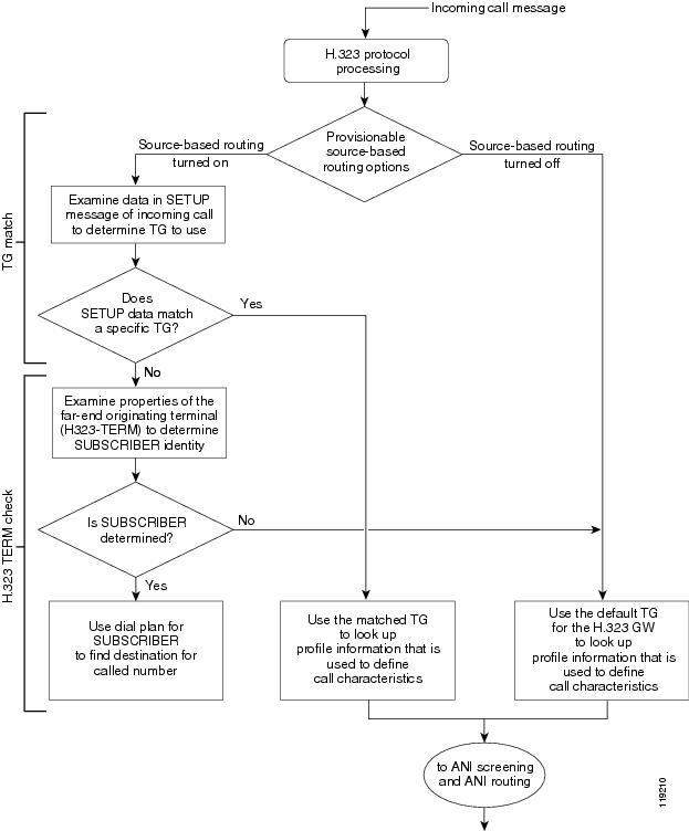
The tables that follow provide details on how to provision inbound call routing, including the processes listed below. Use these diagrams to determine how you need to provision the various parameters that affect inbound routing.
•![]() Figure 3-5—TG match with source-based routing disabled (SRC-BASED-ROUTING set to NONE in the H323-GW table)
Figure 3-5—TG match with source-based routing disabled (SRC-BASED-ROUTING set to NONE in the H323-GW table)
•![]() Figure 3-6—TG match with source-based routing enabled (SRC-BASED-ROUTING set to a value other than NONE in the H323-GW table)
Figure 3-6—TG match with source-based routing enabled (SRC-BASED-ROUTING set to a value other than NONE in the H323-GW table)
•![]() Figure 3-7—H.323 TERM check
Figure 3-7—H.323 TERM check
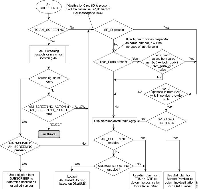
•![]() Figure 3-8—ANI screening and ANI routing
Figure 3-8—ANI screening and ANI routing
Figure 3-5 TG Match with Source-Based Routing Disabled
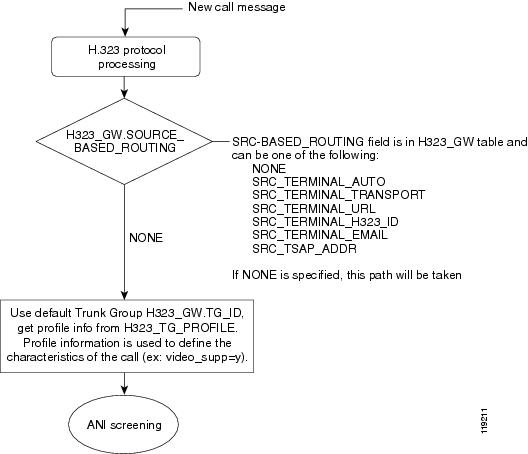
Figure 3-6 TG Match with Source-Based Routing Enabled
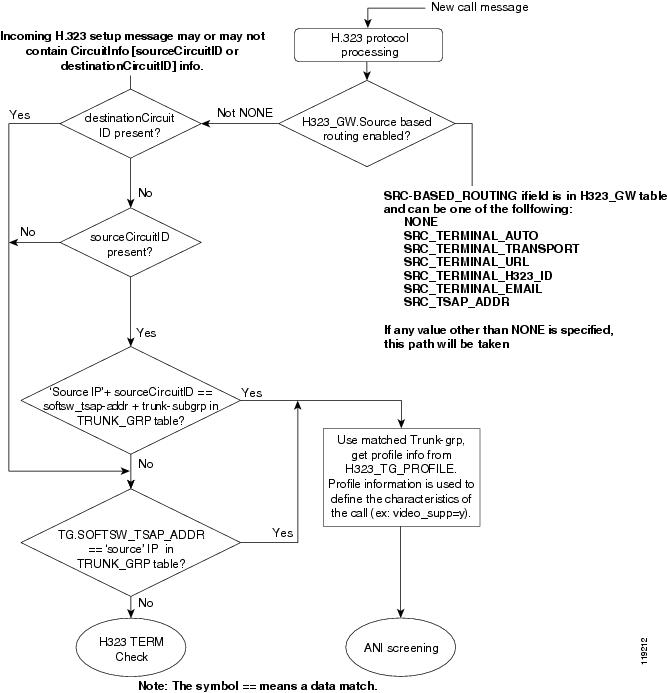
Figure 3-7 H.323 TERM Check
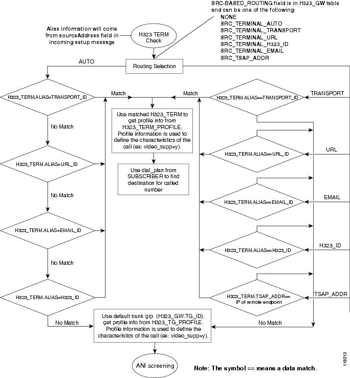
Figure 3-8 ANI Screening and ANI Routing
Provision ANI Screening and Routing
This section provides information on provisioning H.323-based ANI screening and routing options on the Cisco BTS 10200 Softswitch.
ANI Screening vs. ANI-Based Routing
The Cisco BTS 10200 Softswitch provides the option to provision ANI-based screening and ANI-based routing on each TG. For ANI screening, the system compares the ANI received in the incoming SETUP message against the provisioned DN ranges. For ANI routing, the system uses the provisioned dial plan for the subscriber (or main subscriber for a PBX). If the subscriber or PBX is associated with a video-enabled endpoint, the billing record is labeled as video.
The system first checks the TRUNK-GRP table for the TG on which the call was received:
•![]() If the ANI-SCREENING and ANI-BASED-ROUTING tokens in the applicable TRUNK-GRP table are both set to N (no), the system uses the dial plan from the TRUNK-GRP table or the SERVICE-PROVIDER table to determine the destination for the called number. The choice between TRUNK-GRP and SERVICE-PROVIDER tables is based on the additional provisioning options that are described in Figure 3-8.
If the ANI-SCREENING and ANI-BASED-ROUTING tokens in the applicable TRUNK-GRP table are both set to N (no), the system uses the dial plan from the TRUNK-GRP table or the SERVICE-PROVIDER table to determine the destination for the called number. The choice between TRUNK-GRP and SERVICE-PROVIDER tables is based on the additional provisioning options that are described in Figure 3-8.
•![]() If ANI-SCREENING is set to N and ANI-BASED-ROUTING is set to Y, the system performs legacy ANI-based routing according to the provisioning in the DN2SUB table.
If ANI-SCREENING is set to N and ANI-BASED-ROUTING is set to Y, the system performs legacy ANI-based routing according to the provisioning in the DN2SUB table.
•![]() If ANI-SCREENING is set to Y and ANI-BASED-ROUTING is set to N, the system performs ANI screening. Based on the provisionable options that influence this screening, the system can use the dial plan from the SUBSCRIBER table, the TRUNK-GRP table, or the SERVICE-PROVIDER table to route the call (see Figure 3-8).
If ANI-SCREENING is set to Y and ANI-BASED-ROUTING is set to N, the system performs ANI screening. Based on the provisionable options that influence this screening, the system can use the dial plan from the SUBSCRIBER table, the TRUNK-GRP table, or the SERVICE-PROVIDER table to route the call (see Figure 3-8).
•![]() If ANI-SCREENING and ANI-BASED-ROUTING are both set to Y, ANI screening takes precedence.
If ANI-SCREENING and ANI-BASED-ROUTING are both set to Y, ANI screening takes precedence.
Identification of H.323 Terminal Property Based on ANI
The Cisco BTS 10200 Softswitch uses the provisioned ANI data to assist in identifying the terminal property of a phone or PBX, specifically, whether the phone or PBX is video-capable. The system can identify the terminal property of an H.323-based video phone or PBX to which it is directly connected.
If an H.323-based video phone is connected directly to the Cisco BTS 10200 Softswitch, the Cisco BTS 10200 Softswitch recognizes that it is a video call. However, if the call from a video phone goes first to an intermediate H.323 GW or endpoint which is connected to the Cisco BTS 10200 Softswitch, the Cisco BTS 10200 Softswitch must identify the terminal property (for example, video phone) based on information in the H323-TG-PROFILE for the applicable TG for that GW or endpoint. For example, the properties for a PBX-based TG are different than those for a tie TG. It is important to keep this in mind when provisioning H.323 endpoints and TGs.
ANI Screening
If the ANI-SCREENING token in the applicable inbound TRUNK-GRP table is set to Y, the system compares the ANI received in the incoming SETUP message against the DN ranges provisioned in the ANI-SCREENING table:
•![]() If a match is found, the system accepts and routes the call with the appropriate screening-field value in the outgoing message. If the DN is associated with a video-enabled endpoint, the billing record (CDB) is labeled as video.
If a match is found, the system accepts and routes the call with the appropriate screening-field value in the outgoing message. If the DN is associated with a video-enabled endpoint, the billing record (CDB) is labeled as video.
•![]() If a match is not found, the system checks the ACTION token value in the ANI-SCREENING-PROFILE table and takes further action.
If a match is not found, the system checks the ACTION token value in the ANI-SCREENING-PROFILE table and takes further action.
Note ![]() A billing record (CDR) is generated for the call, even if the call is rejected based on ANI screening.
A billing record (CDR) is generated for the call, even if the call is rejected based on ANI screening.
ANI Screening on Incoming Calls
You use commands similar to those shown in the following example to provision ANI screening on incoming calls.
Step 1 ![]() Define the ANI-SCREENING-PROFILE ID. The default ANI-SCREENING-ACTION is set to ALLOW calls. The calls are routed using Dial Plan ID assigned to the incoming Trunk Group.
Define the ANI-SCREENING-PROFILE ID. The default ANI-SCREENING-ACTION is set to ALLOW calls. The calls are routed using Dial Plan ID assigned to the incoming Trunk Group.
Add ANI-SCREENING-PROFILE ID=CHILATA;
Step 2 ![]() Define the Virtual Subscribers for each LATA / RC.
Define the Virtual Subscribers for each LATA / RC.
Add subscriber ID=rac1; sub-profile-id=rac1subp; term-type=none;
Add subscriber ID=rac2; sub-profile-id=rac2subp; term-type=none;
Step 3 ![]() Add ANI-SCREENING records
Add ANI-SCREENING records
Add ANI-SCREENING ID=CHILATA; FROM-DN=312-200-0000; TO-DN=312-999-9999; MAIN-SUB-ID=rac1;
Add ANI-SCREENING ID=CHILATA; FROM-DN=847-200-0000; TO-DN=847-999-9999; MAIN-SUB-ID=rac2;
Step 4 ![]() Add Trunk Group Record
Add Trunk Group Record
Add Trunk-Grp ID=12345; TG=NRS2MGC; call-agent-id=CA123; TG-TYPE=SOFTSW; ANI-SCREENING=Y;
ANI-SCREENING-POFILE-ID=CHILATA; DIAL-PLAN-ID=dp1; POP-ID=CHICAGO;
SOFTSW-TSAP-ADDR=nrs@service-provider.com; TRAFFIC-TYPE=TANDEM;
ANI-Based Routing
If ANI screening is performed successfully on a MAIN-SUB-ID that is associated with a particular TG (for example, if the TG is connected to a PBX), the system performs ANI-based routing using the dial plan for the MAIN-SUB-ID. If the MAIN-SUB-ID is associated with a video-enabled endpoint, the billing record (CDB) is labeled as video.
Provision for Interoperability with Cisco CallManager
Provision the Cisco BTS 10200 Softswitch interface to Cisco CallManager as you would any H.323 GW. Refer to the section on H.323 GW provisioning in the Cisco BTS 10200 Softswitch Provisioning Guide for this procedure. In addition, perform the following provisioning tasks to support interoperability between the two switches:
•![]() Assign a Main Subscriber ID when Cisco CallManager Is Used as a PBX
Assign a Main Subscriber ID when Cisco CallManager Is Used as a PBX
Assign a Main Subscriber ID when Cisco CallManager Is Used as a PBX
The Cisco BTS 10200 Softswitch connects to Cisco CallManager via an H.323 TG. Assign a main subscriber ID only if Cisco CallManager is used as a PBX. The system uses the subscriber ID to perform screening and routing.
Note ![]() If Cisco CallManager is not used as a PBX, do not assign a main subscriber ID, and the system uses the TG properties to perform screening and routing.
If Cisco CallManager is not used as a PBX, do not assign a main subscriber ID, and the system uses the TG properties to perform screening and routing.
To provision a main subscriber ID on the TGs connecting the Cisco BTS 10200 Softswitch to Cisco CallManager, use this procedure:
Step 1 ![]() Log in to a CLI session on the Cisco BTS 10200 Softswitch.
Log in to a CLI session on the Cisco BTS 10200 Softswitch.
Step 2 ![]() To find out if a main subscriber ID is already assigned to the TG towards Cisco CallManager, enter the following command:
To find out if a main subscriber ID is already assigned to the TG towards Cisco CallManager, enter the following command:
show trunk-grp id=<ID of the TG towards Cisco CallManager>;
Example:
show trunk-grp id=TG001;
Step 3 ![]() View the system response and note the displayed value of the main subscriber ID parameter (MAIN-SUB-ID).
View the system response and note the displayed value of the main subscriber ID parameter (MAIN-SUB-ID).
Step 4 ![]() If no value has been provisioned for MAIN-SUB-ID (or if you need to change the current value), enter the appropriate value using the following command:
If no value has been provisioned for MAIN-SUB-ID (or if you need to change the current value), enter the appropriate value using the following command:
change trunk-grp id=<ID of the TG towards Cisco CallManager>; main-sub-id=<Main Subscriber ID for this Cisco CallManager>;
Example:
change trunk-grp id=TG001; main-sub-id=CallManager001;
Provision QoS Codec
To provision the QoS codec on the TGs that connect to Cisco CallManager, use this procedure:
Step 1 ![]() Log in to a CLI session on the Cisco BTS 10200 Softswitch.
Log in to a CLI session on the Cisco BTS 10200 Softswitch.
Step 2 ![]() To find the QOS ID applicable to the TG towards Cisco CallManager, enter the following command:
To find the QOS ID applicable to the TG towards Cisco CallManager, enter the following command:
show trunk-grp id=<ID of the TG towards Cisco CallManager>;
Example:
show trunk-grp id=TG001;
Step 3 ![]() View the system response and note the displayed value of the QoS ID parameter. If the QoS ID is present, go to Step 5.
View the system response and note the displayed value of the QoS ID parameter. If the QoS ID is present, go to Step 5.
Step 4 ![]() If the trunk group QOS-ID parameter is not present, a default value is used. To set the trunk group QOS-ID to the value specified in the QOS table, enter the following command:
If the trunk group QOS-ID parameter is not present, a default value is used. To set the trunk group QOS-ID to the value specified in the QOS table, enter the following command:
change trunk-grp id=TG001; qos_id=gold3;
Step 5 ![]() Enter the following command to display the codec associated with this QOS ID:
Enter the following command to display the codec associated with this QOS ID:
show qos id=<QOS ID>;
Example:
show qos id=gold3;
Step 6 ![]() View the system response and determine the value of the CODEC-TYPE parameter.
View the system response and determine the value of the CODEC-TYPE parameter.
a. ![]() If the value is different from the CODEC-TYPE required by your local work order, change the value by entering the following command:
If the value is different from the CODEC-TYPE required by your local work order, change the value by entering the following command:
change qos id=<QOS ID>; codec-type=<desired codec type>;
Example:
change qos id=gold3; codec-type=PCMU;
b. ![]() If the value is the same as the CODEC-TYPE required by your local work order, no further action is required on this QOS ID.
If the value is the same as the CODEC-TYPE required by your local work order, no further action is required on this QOS ID.
Step 7 ![]() Repeat Step 2 to verify that CODEC-TYPE is set to the desired value.
Repeat Step 2 to verify that CODEC-TYPE is set to the desired value.
Step 8 ![]() Repeat Step 2 through Step 7 for any additional TGs that connect to Cisco CallManager.
Repeat Step 2 through Step 7 for any additional TGs that connect to Cisco CallManager.
Disable GTD
We recommend that GTD be disabled on the TGs toward Cisco CallManager. This can be done either by disabling the GTD at Call Agent (CA) level or at the TG level.

Option to Disable GTD at CA Level
If specified in your local work order, you can disable GTD at the CA level. However, if your local work order requires GTD to be disabled only for certain trunks, skip these steps and go to the "Option to Disable GTD at TG Level" section.
Step 1 ![]() Log in to a CLI session on the Cisco BTS 10200 Softswitch.
Log in to a CLI session on the Cisco BTS 10200 Softswitch.
Step 2 ![]() To display the GTD support status in the CALL-AGENT-PROFILE table, enter the following command:
To display the GTD support status in the CALL-AGENT-PROFILE table, enter the following command:
show call-agent-profile id=<ID of the CA to which the Cisco CallManager is connected>;
Example:
show call-agent-profile id=CA146;
Step 3 ![]() View the system response and determine the value of GTD-SUPP.
View the system response and determine the value of GTD-SUPP.
a. ![]() If the value is Y, change it to N by entering the following command:
If the value is Y, change it to N by entering the following command:
change call-agent-profile id=<ID of the CA to which the Cisco CallManager is connected>; gtd-supp=N;
Example:
change call-agent-profile id=CA146; gtd-supp=N;
b. ![]() If the value is already set to N, GTD is already disabled, and no change is required on GTD.
If the value is already set to N, GTD is already disabled, and no change is required on GTD.
Step 4 ![]() Repeat Step 2 to verify that GTD-SUPP is set to N.
Repeat Step 2 to verify that GTD-SUPP is set to N.
Option to Disable GTD at TG Level
If specified in your local work order, you can disable GTD at the individual TG level.
Step 1 ![]() Log in to a CLI session on the Cisco BTS 10200 Softswitch.
Log in to a CLI session on the Cisco BTS 10200 Softswitch.
Step 2 ![]() To display the GTD support status in the H323-TG-PROFILE table, enter the following command:
To display the GTD support status in the H323-TG-PROFILE table, enter the following command:
show h323-tg-profile id=<ID of the TG-profile applicable to the Cisco CallManager>;
Example:
show h323-tg-profile id=TG501;
Step 3 ![]() View the system response and determine the value of GTD-SUPP.
View the system response and determine the value of GTD-SUPP.
a. ![]() If the value is Y, change it to N by entering the following command:
If the value is Y, change it to N by entering the following command:
change h323-tg-profile id=<ID of the TG-profile applicable to the Cisco CallManager>; gtd-supp=N;
Example:
change h323-tg-profile id=TG501; gtd-supp=N;
b. ![]() If the value is N, GTD is already disabled for this H323-TG-PROFILE. No further action is required on this H323-TG-PROFILE.
If the value is N, GTD is already disabled for this H323-TG-PROFILE. No further action is required on this H323-TG-PROFILE.
Step 4 ![]() Repeat Step 2 to verify that GTD-SUPP is set to N in the H323-TG-PROFILE table.
Repeat Step 2 to verify that GTD-SUPP is set to N in the H323-TG-PROFILE table.
Step 5 ![]() Repeat Step 2 through Step 4 for any additional Cisco BTS 10200 Softswitch H.323 TGs connected to other Cisco CallManagers.
Repeat Step 2 through Step 4 for any additional Cisco BTS 10200 Softswitch H.323 TGs connected to other Cisco CallManagers.
Provision Annex E Functionality
This section highlights the special parameters that must be provisioned to support Annex E functionality.
Note ![]() For basic H.323 provisioning, refer to the section on H.323-GW provisioning in the Cisco BTS 10200 Softswitch Provisioning Guide.
For basic H.323 provisioning, refer to the section on H.323-GW provisioning in the Cisco BTS 10200 Softswitch Provisioning Guide.
Step 1 ![]() Log in to a CLI session on the Cisco BTS 10200 Softswitch.
Log in to a CLI session on the Cisco BTS 10200 Softswitch.
Step 2 ![]() To provision Annex E support for the H.323 GW instance on the Cisco BTS 10200 Softswitch, enter the following command:
To provision Annex E support for the H.323 GW instance on the Cisco BTS 10200 Softswitch, enter the following command:
change h323-gw id=city1gw; annexe-supp=Y; annexe-udp-port=2517; annexe-retransmit-timer=500; annexe-retransmit-multiplier=2; annexe-retransmit-attempts=8;
where:
•![]() h323-gw id—Name used to identify the H.323 GW instance. This value must be a string of 1 to 16 ASCII characters, assigned by the service provider.
h323-gw id—Name used to identify the H.323 GW instance. This value must be a string of 1 to 16 ASCII characters, assigned by the service provider.
•![]() annexe-supp—This flag indicates whether this H.323 GW instance supports Annex E. The default value is Y. This value must be kept as Y to support Annex E. If the remote H.323 endpoint does not support Annex E UDP signaling, the Cisco BTS 10200 Softswitch automatically adjusts and uses TCP signaling toward that endpoint.
annexe-supp—This flag indicates whether this H.323 GW instance supports Annex E. The default value is Y. This value must be kept as Y to support Annex E. If the remote H.323 endpoint does not support Annex E UDP signaling, the Cisco BTS 10200 Softswitch automatically adjusts and uses TCP signaling toward that endpoint.
–![]() If the Cisco BTS 10200 Softswitch H323-GW instance is configured as Annex E enabled (annexe-supp=Y), the Cisco BTS 10200 Softswitch indicates its Annex E capabilities while registering with the H.323 GK.
If the Cisco BTS 10200 Softswitch H323-GW instance is configured as Annex E enabled (annexe-supp=Y), the Cisco BTS 10200 Softswitch indicates its Annex E capabilities while registering with the H.323 GK.
–![]() For RAS-routed calls, the GK negotiates all Annex E capabilities between the Cisco BTS 10200 Softswitch and the far-end H.323 endpoint, and notifies the originating endpoint to use Annex E.
For RAS-routed calls, the GK negotiates all Annex E capabilities between the Cisco BTS 10200 Softswitch and the far-end H.323 endpoint, and notifies the originating endpoint to use Annex E.
–![]() If the Cisco BTS 10200 Softswitch H323-GW instance is Annex E enabled (annexe-supp=Y), but the far-end H.323 endpoint is not, the Cisco BTS 10200 Softswitch can still complete calls using regular TCP mode.
If the Cisco BTS 10200 Softswitch H323-GW instance is Annex E enabled (annexe-supp=Y), but the far-end H.323 endpoint is not, the Cisco BTS 10200 Softswitch can still complete calls using regular TCP mode.
–![]() If the Cisco BTS 10200 Softswitch H323-GW instance is configured as Annex E disabled (annexe-supp=N), it cannot receive inbound Annex E UDP calls. It can receive inbound calls using TCP signaling only.
If the Cisco BTS 10200 Softswitch H323-GW instance is configured as Annex E disabled (annexe-supp=N), it cannot receive inbound Annex E UDP calls. It can receive inbound calls using TCP signaling only.
•![]() annexe-udp-port—This number specifies the port to be used to receive incoming Annex E messages. The default value is 2517, but a unique value must be assigned to each H.323 GW instance on the Cisco BTS 10200 Softswitch.
annexe-udp-port—This number specifies the port to be used to receive incoming Annex E messages. The default value is 2517, but a unique value must be assigned to each H.323 GW instance on the Cisco BTS 10200 Softswitch.
•![]() annexe-retransmit-timer—This is the initial value of the retransmit timer which determines when to resend AnnexE packets if an ACK message has not been received. All subsequent retransmissions are based on exponential back-off algorithm using annexe-retransmit-multiplier. The valid range is a number from 1 to 30,000 (in milliseconds), and the default value is 500.
annexe-retransmit-timer—This is the initial value of the retransmit timer which determines when to resend AnnexE packets if an ACK message has not been received. All subsequent retransmissions are based on exponential back-off algorithm using annexe-retransmit-multiplier. The valid range is a number from 1 to 30,000 (in milliseconds), and the default value is 500.
•![]() annexe-retransmit-multiplier—The multiplication factor of the previous retransmit interval that is used for subsequent Annex E packet retransmissions. The valid range is 1 to 10, and the default value is 2.
annexe-retransmit-multiplier—The multiplication factor of the previous retransmit interval that is used for subsequent Annex E packet retransmissions. The valid range is 1 to 10, and the default value is 2.
•![]() annexe-retransmit-attempts—Specifies how many attempts to resend a message to the remote entity should be made before the message is dropped. The valid range is 1 to 10, and the default value is 8.
annexe-retransmit-attempts—Specifies how many attempts to resend a message to the remote entity should be made before the message is dropped. The valid range is 1 to 10, and the default value is 8.
Step 3 ![]() Use this step to control the H323-GW instance INS (if necessary):
Use this step to control the H323-GW instance INS (if necessary):
a. ![]() To display the service status of the H323-GW instance, enter the following command:
To display the service status of the H323-GW instance, enter the following command:
status h323-gw id=city1gw;
b. ![]() View the display to see the status of the H323-GW instance.
View the display to see the status of the H323-GW instance.
c. ![]() If the displayed status is OOS, continue with Substep d. If the displayed status is INS, go to Step 4.
If the displayed status is OOS, continue with Substep d. If the displayed status is INS, go to Step 4.
d. ![]() Enter the following commands to place the H323-GW instance INS:
Enter the following commands to place the H323-GW instance INS:
control h323-gw id=city1gw; target-state=INS;
e. ![]() Enter the following command and verify that the status of the H323-GW instance is displayed as OOS:
Enter the following command and verify that the status of the H323-GW instance is displayed as OOS:
status h323-gw id=city1gw;
Step 4 ![]() To provision Annex E support on the outgoing H.323 TGs, enter the following command:
To provision Annex E support on the outgoing H.323 TGs, enter the following command:
CLI> change h323-tg-profile id=h323tg01; ras=Y; annexe-supp=Y; call-connect-mode=FAST-START; transport-pref-mode=UDP-MODE;
where:
•![]() h323-tg-profile id—This is the unique ID for this H323-TG-PROFILE. The format is 1 to 16 ASCII characters, assigned by the service provider.
h323-tg-profile id—This is the unique ID for this H323-TG-PROFILE. The format is 1 to 16 ASCII characters, assigned by the service provider.
•![]() ras—Specifies whether RAS signaling to H.323 GK is supported. The allowed values are Y and N. Default value is Y. Set this value to Y to enable communications with the GK.
ras—Specifies whether RAS signaling to H.323 GK is supported. The allowed values are Y and N. Default value is Y. Set this value to Y to enable communications with the GK.
•![]() annexe-supp—This flag indicates whether this H323-TG-PROFILE supports Annex E. The default value is Y. This value must be kept as Y to support Annex E. If the remote H.323 endpoint does not support Annex E UDP signaling, the Cisco BTS 10200 Softswitch automatically adjusts and uses TCP signaling to communicate with that endpoint.
annexe-supp—This flag indicates whether this H323-TG-PROFILE supports Annex E. The default value is Y. This value must be kept as Y to support Annex E. If the remote H.323 endpoint does not support Annex E UDP signaling, the Cisco BTS 10200 Softswitch automatically adjusts and uses TCP signaling to communicate with that endpoint.
•![]() call-connect-mode—Specifies the preferred call start mode for outgoing H.323 calls. Possible values are FAST-START (default value) and SLOW-START. If the remote H.323 endpoint does not support fast-start parameters, the Cisco BTS 10200 Softswitch automatically adjusts and uses slow-start mode toward that endpoint. The fast-start parameter is based on the fast-connect procedures described in ITU-T Standard H.323.
call-connect-mode—Specifies the preferred call start mode for outgoing H.323 calls. Possible values are FAST-START (default value) and SLOW-START. If the remote H.323 endpoint does not support fast-start parameters, the Cisco BTS 10200 Softswitch automatically adjusts and uses slow-start mode toward that endpoint. The fast-start parameter is based on the fast-connect procedures described in ITU-T Standard H.323.
•![]() transport-pref-mode—Specifies what transport layer protocol to use to transmit H.323 signaling messages. Valid values are as follows:
transport-pref-mode—Specifies what transport layer protocol to use to transmit H.323 signaling messages. Valid values are as follows:
–![]() TCP-MODE—Use TCP to transport messages.
TCP-MODE—Use TCP to transport messages.
–![]() UDP-MODE (default value)—Use Annex E UDP-based message transport facility. If the remote H.323 endpoint does not support UDP, the Cisco BTS 10200 adjusts automatically to use TCP mode. This token must be set to UDP-MODE before annexe-supp can be set to Y.
UDP-MODE (default value)—Use Annex E UDP-based message transport facility. If the remote H.323 endpoint does not support UDP, the Cisco BTS 10200 adjusts automatically to use TCP mode. This token must be set to UDP-MODE before annexe-supp can be set to Y.
Step 5 ![]() If you have not already done so, enable Annex E support on the far-end H.323 endpoint.
If you have not already done so, enable Annex E support on the far-end H.323 endpoint.
Note ![]() To enable Annex E support for a particular H.323 TG, you must enable Annex E for the H.323 GW instance on the Cisco BTS 10200 Softswitch and enable Annex E support for the far-end H.323 endpoint.
To enable Annex E support for a particular H.323 TG, you must enable Annex E for the H.323 GW instance on the Cisco BTS 10200 Softswitch and enable Annex E support for the far-end H.323 endpoint.
Provision Additional H.323 Options
This section describes a number of advanced H.323 provisioning options that affect protocol transparency and special H.323 messaging features supported by the Cisco BTS 10200 Softswitch. In the most common network configurations it is generally not necessary to provision these parameters—the default values are sufficient. However, these advanced options can be provisioned to nondefault values if desired. The information is contained in the following two sections:
•![]() H.323 Protocol Transparency Functions
H.323 Protocol Transparency Functions
•![]() Additional Advanced H.323 Features
Additional Advanced H.323 Features
H.323 Protocol Transparency Functions
The Cisco BTS 10200 Softswitch supports the interconnection of multiple H.323-based devices by transparently passing certain H.323 messages in calls that transit the Cisco BTS 10200 Softswitch. There are three transparency functions that include optional service provider provisioning:
•![]() Call-Connect-Mode Transparency
Call-Connect-Mode Transparency
•![]() Call-Proceeding Message Transparency
Call-Proceeding Message Transparency
•![]() Transparency of H.245 Tunneling Mode
Transparency of H.245 Tunneling Mode
Call-Connect-Mode Transparency
The CALL-CONNECT-MODE token in the H323-TG-PROFILE and H323-TERM-PROFILE tables specifies the call setup method used for outbound and inbound H.323-based calls.
Note ![]() If this token is configured as FAST-START and the far-end H.323 endpoint does not support FAST-START, the Cisco BTS 10200 Softswitch falls back to the SLOW-START method.
If this token is configured as FAST-START and the far-end H.323 endpoint does not support FAST-START, the Cisco BTS 10200 Softswitch falls back to the SLOW-START method.
Note ![]() If the incoming call is using slow-start procedures, and this token is configured as FAST-START, this call leg functions as slow-start only.
If the incoming call is using slow-start procedures, and this token is configured as FAST-START, this call leg functions as slow-start only.
Permitted values for this token are as follows:
•![]() AUTO (default)—Use fast-connect method for calls originated from non-H.323 endpoints and for outbound H.323 calls. For H.323 transit calls, use the same method for outbound H.323 calls as you use for inbound H.323 calls.
AUTO (default)—Use fast-connect method for calls originated from non-H.323 endpoints and for outbound H.323 calls. For H.323 transit calls, use the same method for outbound H.323 calls as you use for inbound H.323 calls.
Note ![]() For most applications, the default value (AUTO) is sufficient.
For most applications, the default value (AUTO) is sufficient.
•![]() FAST-START—Always use the fast-start procedures for outbound H.323 calls (except where an incoming call uses slow-start procedures), regardless of the originating (inbound) call protocol type.
FAST-START—Always use the fast-start procedures for outbound H.323 calls (except where an incoming call uses slow-start procedures), regardless of the originating (inbound) call protocol type.
•![]() SLOW-START—Always use the slow-start procedures during call setup, regardless of the originating (inbound) call protocol type.
SLOW-START—Always use the slow-start procedures during call setup, regardless of the originating (inbound) call protocol type.
Call-Proceeding Message Transparency
The SEND-CALL-PROCEEDING token in the H323-TG-PROFILE and H323-TERM-PROFILE tables specifies the conditions for sending a Call Proceeding message from the terminating endpoint to the originating endpoint.
The permitted values for this token are as follows:
•![]() AUTO (default)—Generate and send a Call Proceeding message on the originating H.323 leg when the terminating leg is non-H.323. Pass the Call Proceeding message end-to-end for H.323-to-H.323 calls.
AUTO (default)—Generate and send a Call Proceeding message on the originating H.323 leg when the terminating leg is non-H.323. Pass the Call Proceeding message end-to-end for H.323-to-H.323 calls.
Note ![]() For most applications, the default value (AUTO) is sufficient.
For most applications, the default value (AUTO) is sufficient.
•![]() LOCAL—Always generate and send a Call Proceeding message on the originating H.323 leg, regardless of the protocol type used on the terminating leg.
LOCAL—Always generate and send a Call Proceeding message on the originating H.323 leg, regardless of the protocol type used on the terminating leg.
•![]() DISABLE—Never send a Call Proceeding message.
DISABLE—Never send a Call Proceeding message.
Note ![]() This flag is not applicable for incoming calls from the H.323 network to a local subscriber controlled by the Cisco BTS 10200 Softswitch and being forwarded or transferred to the H.323 network.
This flag is not applicable for incoming calls from the H.323 network to a local subscriber controlled by the Cisco BTS 10200 Softswitch and being forwarded or transferred to the H.323 network.
Transparency of H.245 Tunneling Mode
The H245-TUNNELING token in the H323-TG-PROFILE and H323-TERM-PROFILE tables specifies whether to enable or disable H.245 tunneling mode on each of the call legs. When H.245 tunneling is enabled, all H.245 messages are tunneled inside a FACILITY message instead of through a separate H.245 TCP channel.
The permitted values for this token are as follows:
•![]() AUTO (default)—The system automatically determines whether to enable or disable H.245 tunneling:
AUTO (default)—The system automatically determines whether to enable or disable H.245 tunneling:
–![]() Use H.245 tunneling on the H.323-based call leg for calls between H.323 and non-H.323 endpoints.
Use H.245 tunneling on the H.323-based call leg for calls between H.323 and non-H.323 endpoints.
–![]() For H.323 transit calls, the system automatically considers what the peer leg is using as its tunneling mode to help determine whether to enable or disable H.245 tunneling.
For H.323 transit calls, the system automatically considers what the peer leg is using as its tunneling mode to help determine whether to enable or disable H.245 tunneling.
Note ![]() For most applications, the default value (AUTO) is sufficient.
For most applications, the default value (AUTO) is sufficient.
Note ![]() If H245-TUNNELING in the H323-TG-PROFILE (or H323-TERM-PROFILE) tables for either one of the endpoints in the call is not set to AUTO, the system enables or disables H.245 tunneling for each leg of the call individually.
If H245-TUNNELING in the H323-TG-PROFILE (or H323-TERM-PROFILE) tables for either one of the endpoints in the call is not set to AUTO, the system enables or disables H.245 tunneling for each leg of the call individually.
•![]() ENABLE—Always use H.245 tunneling for outgoing calls, without considering the type of incoming call-leg protocol.
ENABLE—Always use H.245 tunneling for outgoing calls, without considering the type of incoming call-leg protocol.
•![]() DISABLE—Always disable H.245 tunneling for outgoing call legs and use a separate H.245 TCP channel.
DISABLE—Always disable H.245 tunneling for outgoing call legs and use a separate H.245 TCP channel.
Note ![]() If H245-TUNNELING is set to AUTO or ENABLE, the FACILITY-SUPP token should be set to Y.
If H245-TUNNELING is set to AUTO or ENABLE, the FACILITY-SUPP token should be set to Y.
H.323-Based T.38 Fax Parameters
This section provides tips on provisioning H.323-based parameters for T.38 fax.
Provisioning fax-t38-enabled in the QoS Table
This parameter is a binary flag (Y/N) with default = Y. SIP-to-SIP and H.323-to-H.323 calls ignore this flag. QOS is optional for endpoints and trunks. The settings work as follows:
•![]() If no QOS is provisioned, or if this flag is set all Y (default), then this flag does not change T.38 fax feature behavior.
If no QOS is provisioned, or if this flag is set all Y (default), then this flag does not change T.38 fax feature behavior.
•![]() MGCP/TGCP/NCS/H.323 endpoints—If either endpoint in the call (including SIP) has a QOS entry and this flag set to N, then the Cisco BTS 10200 Softswitch will indicate to each MGCP/H.323 endpoint to not use T.38 procedures regardless of the T.38 loose flag setting in the mgw-profile table.
MGCP/TGCP/NCS/H.323 endpoints—If either endpoint in the call (including SIP) has a QOS entry and this flag set to N, then the Cisco BTS 10200 Softswitch will indicate to each MGCP/H.323 endpoint to not use T.38 procedures regardless of the T.38 loose flag setting in the mgw-profile table.
Table 3-3 shows the conditions under which the Cisco BTS 10200 uses T.38 fax protocol when fax is detected. This depends on the value of the QOS FAX_T38_ENABLED field for each endpoint involved in the call, and the protocol type of each endpoint. The symbols have the following significance:
•![]() T.38: The Cisco BTS 10200 uses T.38 protocol for fax transmission.
T.38: The Cisco BTS 10200 uses T.38 protocol for fax transmission.
•![]() X: The Cisco BTS 10200 does not use T.38 protocol for fax transmission.
X: The Cisco BTS 10200 does not use T.38 protocol for fax transmission.
•![]() T.38*: Since one of the field values in this combination is set to N, the MGCP endpoint involved in this call does not receive the local connection option (L:fxr:fx/t38) in the initial CRCX request from Cisco BTS 10200. However, if the endpoint receives T.38 SDP from the remote end detecting fax, then it is assumed here to support the switch to T.38 media connection.
T.38*: Since one of the field values in this combination is set to N, the MGCP endpoint involved in this call does not receive the local connection option (L:fxr:fx/t38) in the initial CRCX request from Cisco BTS 10200. However, if the endpoint receives T.38 SDP from the remote end detecting fax, then it is assumed here to support the switch to T.38 media connection.
Provisioning remote-fax-port-retrieval-msg in the H323 TG Profile and H323 Term Profile Tables
The H.323 GW can report the UDP port for T.38 fax transmission in either H.245 OLC (default) or OLC ACK. To provision the H.323 interface, use the REMOTE-FAX-PORT- RETRIEVAL-MSG field in the h323-tg-profile and h323-term-profile tables. This parameter indicates the field in which the system should look for this value.
Note ![]() Cisco IOS H323 GWs report the UDP port in OLC.
Cisco IOS H323 GWs report the UDP port in OLC.
Provisioning H.323 Parameters in the CA-CONFIG Table
The H.323 interface uses the following global parameters when negotiating the T.38 fax connection during voice call establishment when interworking with a non-H323 endpoint.
•![]() T38_MAX _BIT_RATE, Default 14.4—This is default bit rate for T38 fax.
T38_MAX _BIT_RATE, Default 14.4—This is default bit rate for T38 fax.
•![]() T38_MAX _BUFFER_SIZE, Default 200—This is default maximum buffer size for T38 fax.
T38_MAX _BUFFER_SIZE, Default 200—This is default maximum buffer size for T38 fax.
•![]() T38_MAX _DATAGRAM_SIZE, Default 72—This is default maximum datagram size for T38 fax.
T38_MAX _DATAGRAM_SIZE, Default 72—This is default maximum datagram size for T38 fax.
Additional Advanced H.323 Features
Additional H.323 advanced features include:
•![]() DTMF Relay Support on MGCP-to-H.323 Calls
DTMF Relay Support on MGCP-to-H.323 Calls
•![]() Configurable Status Enquiry Timer
Configurable Status Enquiry Timer
•![]() Reattempt, Route Advance, and Hairpinning (Redirection)
Reattempt, Route Advance, and Hairpinning (Redirection)
DTMF Relay Support on MGCP-to-H.323 Calls
For MGCP-to-H.323 (fast-connect) calls, RFC 2833 capabilities are advertised for the H.323 call leg based on static information provisioned for the H.323 TG or terminal. Ensure that all far-end H.323 capabilities are provisioned in the appropriate table:
•![]() For incoming H.323 calls, provision the far-end H.323 capabilities in the incoming H323-TG-PROFILE table (or H323-TERM-PROFILE table)
For incoming H.323 calls, provision the far-end H.323 capabilities in the incoming H323-TG-PROFILE table (or H323-TERM-PROFILE table)
•![]() For outgoing H.323 calls, provision the far-end H.323 capabilities in the outgoing H323-TG-PROFILE table (or H323-TERM-PROFILE table)
For outgoing H.323 calls, provision the far-end H.323 capabilities in the outgoing H323-TG-PROFILE table (or H323-TERM-PROFILE table)
Asymmetric Codec Resolution
To enable the asymmetric codec resolution feature, set the CODEC-NEG-SUPP field in H323-TG-PROFILE (for H323 trunk-grp) or H323-TERM-PROFILE (for H323 subscriber) to Y, which is the default value. The configurable fields CODEC-NEG-TIMER and CODEC-NEG-ATTEMPTS in the H323-GW table control the codec resolution procedure. If the CODEC-NEG-SUPP field is configured as Y, it is not necessary for a codec to be configured in the QOS table of the incoming/outgoing trunk-grp.
If the CODEC-NEG-SUPP field (in H323-TG-PROFILE or H323-TERM-PROFILE) is configured as N (no), the Cisco BTS 10200 Softswitch expects the far-end H.323 device (particularly one not using the fast-connect procedure) to use the codec configured in the QOS table entry of both the incoming and outgoing trunk-grp tables (or subscriber table). If the codecs of the two end devices do not match, the call will fail.
Note ![]() For all IOS gateways, set this token to Y. For connection to Cisco CallManager, set this token to N. Contact the Cisco TAC if you need additional details on this setting.
For all IOS gateways, set this token to Y. For connection to Cisco CallManager, set this token to N. Contact the Cisco TAC if you need additional details on this setting.
Facility Message
The FACILITY message is used primarily for passing tunneling and other special information. The service provider provisions the FACILITY-SUPP flag in the H323-TG-PROFILE (or H323-TERM-PROFILE) table to indicate whether the far-end device supports receiving of the FACILITY message. The default value is Y. If H245-TUNNELING is set to AUTO or ENABLE, then the FACILITY-SUPP token should be set to Y.
Note ![]() For connection to Cisco CallManager, set FACILITY-SUPP to N.
For connection to Cisco CallManager, set FACILITY-SUPP to N.
Media Cut-Through
The CUT-THRU-PARAM token can be used to trigger the far-end device to perform media cut-through. The service provider provisions the CUT-THRU-PARAM token in the incoming H323-TG-PROFILE (or H323-TERM-PROFILE) table to indicate whether to trigger cut-through on the far-end device. The default value is AUTO.
Note ![]() For connection to Cisco CallManager and for most other applications, the default value (AUTO) is sufficient.
For connection to Cisco CallManager and for most other applications, the default value (AUTO) is sufficient.
Empty Capability Set
Use the ECS-METHOD token in the H323-TG-PROFILE (or H323-TERM-PROFILE) table to set special handling of the ECS message.
Note ![]() For connection to Cisco CallManager and for most other applications, the default value (AUTO) is sufficient.
For connection to Cisco CallManager and for most other applications, the default value (AUTO) is sufficient.
•![]() AUTO (Default)—For connection to Cisco CallManager, the Cisco BTS 10200 Softswitch uses the ALL-PAUSE method. For all other types of H.323 devices, it uses the LOCAL-PAUSE method.
AUTO (Default)—For connection to Cisco CallManager, the Cisco BTS 10200 Softswitch uses the ALL-PAUSE method. For all other types of H.323 devices, it uses the LOCAL-PAUSE method.
•![]() LOCAL-PAUSE—The far-end H.323 device receiving the ECS message closes the forward logical channel.
LOCAL-PAUSE—The far-end H.323 device receiving the ECS message closes the forward logical channel.
•![]() ALL-PAUSE—The far-end H.323 device receiving the ECS message closes the forward logical channel. The local side (Cisco BTS 10200 Softswitch) also closes its forward logical channel.
ALL-PAUSE—The far-end H.323 device receiving the ECS message closes the forward logical channel. The local side (Cisco BTS 10200 Softswitch) also closes its forward logical channel.
Configurable Status Enquiry Timer
If a CA failover occurs, the Cisco BTS 10200 Softswitch sends a STATUS ENQ message and starts the STATUS ENQ timer for each call. Provision the STATUS-ENQ-TIMER in the H323-GW table. The range of values is 1 to 30 (seconds) and the default is 4.
Reattempt, Route Advance, and Hairpinning (Redirection)
By default, the system attempts to send the FastStart element in the CALLPROCEEDING message if it is available; otherwise, the element is sent in the ALERTING or PROGRESS message, whichever is sent first. For H.323-to-H.323 (transit) calls, sending the FastStart element in the CALLPROCEEDING message could cause reattempt, route advance, or hairpinning to fail. To support these features for transit calls, you must set the SEND-FS-CALLP token (in the h323-tg-profile or h323-term-profile table) to N (No) to suppress sending the FastStart element in the CALLPROCEEDING message. The default value of this token is Y.
Tip ![]() The SEND-FS-CALLP token is new in Release 4.5.1. The MISC-UNSUPP token is not used in this release.
The SEND-FS-CALLP token is new in Release 4.5.1. The MISC-UNSUPP token is not used in this release.
Table 3-4 lists the appropriate settings for the SEND-FS-CALLP token.
Overload Control
An overload condition exists when Cisco BTS 10200 resources cannot handle system tasks. Increases in call traffic or messages indirectly related to call traffic usually cause overload. The Overload Control feature supports the Cisco BTS 10200 Call Agent (CA) and Feature Server (FS). Overload Control detects, controls, and manages overload from all types of networks including H.323 networks.
When the Cisco BTS 10200 experiences a machine congestion level (MCL) that exceeds MCL0, with regard to the H.323 protocol, Overload Control feature causes H.323 to send a Resource Availability Indicator (RAI) message.
To support Overload Control, the Cisco BTS 10200 adds
•![]() New measurement—The measurement H323_OC_SETUP_REJECTED provides the total number of incoming H.323 Setup messages rejected by the Cisco BTS 10200 due to overload.
New measurement—The measurement H323_OC_SETUP_REJECTED provides the total number of incoming H.323 Setup messages rejected by the Cisco BTS 10200 due to overload.
•![]() H323-GW table tokens—The following tokens are added to the H323-GW table:
H323-GW table tokens—The following tokens are added to the H323-GW table:
–![]() SEND-RAI—Indicates whether to send RAI message to the GK when overload condition occurs. VARCHAR(1): Y/N (Default=Y).
SEND-RAI—Indicates whether to send RAI message to the GK when overload condition occurs. VARCHAR(1): Y/N (Default=Y).
–![]() ALT-ENDPOINT1—When provisioned, the Cisco BTS 10200 reports an alternate endpoint in the Registration Request (RRQ) message to the GK.
ALT-ENDPOINT1—When provisioned, the Cisco BTS 10200 reports an alternate endpoint in the Registration Request (RRQ) message to the GK.
Also, contains the TSAP address of the endpoint in the format 10.89.227.114:1720. (Default=NULL).
–![]() ALT-ENDPOINT2—TSAP address of the second alternate endpoint.
ALT-ENDPOINT2—TSAP address of the second alternate endpoint.
–![]() ALT-ENDPOINT3—TSAP address of the third alternate endpoint.
ALT-ENDPOINT3—TSAP address of the third alternate endpoint.
–![]() ALT-ENDPOINT4—TSAP address of the fourth alternate endpoint.
ALT-ENDPOINT4—TSAP address of the fourth alternate endpoint.
–![]() ALT-ENDPOINT5—TSAP address of the fifth alternate endpoint.
ALT-ENDPOINT5—TSAP address of the fifth alternate endpoint.
•![]() H323-TG-Profile Table tokens—The following token is added to the H323-TG-Profile table:
H323-TG-Profile Table tokens—The following token is added to the H323-TG-Profile table:
–![]() PEER-GW-OVERLOAD-TIMER—Shows the number of seconds to mark a trunk group congested and reroute or drop calls to the trunk group. INTEGER: 0—300 (default = 60). A value of 0 disables this timer.
PEER-GW-OVERLOAD-TIMER—Shows the number of seconds to mark a trunk group congested and reroute or drop calls to the trunk group. INTEGER: 0—300 (default = 60). A value of 0 disables this timer.
Note ![]() This behavior does not apply if RAS is enabled on the trunk group. In this case, it is the GK's responsibility to throttle, reroute, or reject the call to the terminating endpoint.
This behavior does not apply if RAS is enabled on the trunk group. In this case, it is the GK's responsibility to throttle, reroute, or reject the call to the terminating endpoint.
Example of Provisioning Script
This section provides a sample provisioning script, which you can use as a guide to provision a new system.
##################################################################
# Add Call Agent
###################################################################
ADD CALL_AGENT ID=CA146; TSAP_ADDR_SIDEA=172.28.255.252; EMS_PRIMARY_TSAP=172.28.255.251;
EMS_SECONDARY_TSAP=172.28.255.251; MGW_MONITORING_ENABLED=Y;
##################################################################
# Add Current Concerned NPA#
##################################################################
ADD NDC DIGIT_STRING=972;
ADD EXCHANGE_CODE NDC=972; EC=813;
ADD OFFICE_CODE CALL_AGENT_ID=CA146; NDC=972; EC=813; DN_GROUP=xxxx;
################################################################################
# Add POP
#################################################################################
ADD POP ID=27;
################################################################################
# Add Service Providers
#################################################################################
# This service provider can be used to match incoming h323 call that has used a
# destinationCircuitInfoID set to this service provider
ADD SERVICE_PROVIDER ID=SP1; SP_BASED_ROUTING=N; USE_DIAL_PLAN=Y; ANI_WB_LIST=NONE;
#################################################################################
# Add H323 TRUNKS
#################################################################################
ADD H323_TG_PROFILE ID=TRUNK_PROFILE_1; RAS=Y; H323_TCP_TIMER=10; DTMF_CISCO_RTP_SUPP=N;
DTMF_H245_ALPHA_SUPP=Y; DTMF_H245_SIGNAL_SUPP=N; DTMF_RFC2833=N;
DTMF_PREF_MODE=DTMF_H245_ALPHA; H245_SESSION_MODE=AUTO; CALL_CONNECT_MODE=AUTO;
H245_TUNNELING=AUTO; SEND_CALL_PROCEEDING=AUTO; REMOTE_FAX_PORT_RETRIEVAL_MSG=H245_OLC;
SEND_FS_CALLP=Y
# Add QOS ID to enable T38 Fax
ADD QOS ID=PCMU; CODEC_TYPE=PCMU; FAX_T38_ENABLED=Y;
# This trunk can be used as a match for incoming h323 calls matched on IP:port
ADD TRUNK_GRP ID=318; CALL_AGENT_ID=CA146; TG_TYPE=H323; TG_PROFILE_ID=TRUNK_PROFILE_1;
DIAL_PLAN_ID=cdp1; ANI_BASED_ROUTING=N; SOFTSW_TSAP_ADDR=10.89.227.114:1720; QOS_ID=PCMU;
# This trunk group would be used to match incoming h323 call from CARRIER_A that is
# associated with H323 GW 10.89.227.115, also apply ANI based routing
# or for outbound h323 call with sourceCircuitInfo=CARRIER_A;
ADD TRUNK_GRP ID=418; CALL_AGENT_ID=CA146; TG_TYPE=H323; TG_PROFILE_ID=TRUNK_PROFILE_1;
DIAL_PLAN_ID=cdp1; ANI_BASED_ROUTING=Y; SOFTSW_TSAP_ADDR=10.89.227.115:1720;
TRUNK_SUB_GROUP=CARRIER_A;
##############################
# ANI SCREENING AND ROUTING
##############################
ADD SUBSCRIBER_PROFILE ID=sp0; DIAL_PLAN_ID=cdp1; POP_ID=27;
ADD TRUNK_GRP ID=469; CALL_AGENT_ID=CA146; TG_TYPE=H323; TG_PROFILE_ID=TRUNK_PROFILE_1;
DIAL_PLAN_ID=cdp1; ANI_SCREENING=Y; ANI-SCREENING-ACTION=ALLOW;
ADD H323_TG_PROFILE ID=video_ani_tg; RAS=Y; H245_SESSION_MODE=H245-FLOWAROUND;
CALL_CONNECT_MODE=AUTO; H245_TUNNELING=AUTO; SEND_CALL_PROCEEDING=AUTO;
ADD TRUNK-GRP ID=478; CALL-AGENT-ID=CA146; TG-TYPE=H323; TG-PROFILE-ID=VIDEO_ANI_BLOCK;
ADD SUBSCRIBER ID=ANI_972671_SUB; CATEGORY=PBX; GRP=Y; PRIVACY=USER; SEND-BDN-AS-CPN=N;
SEND-BDN-EMG=N; SUB-PROFILE-ID=SP0; TERM-TYPE=TG; TGN-ID=NULL;
ADD ANI-SCREENING TGN-ID=469; ID=SCREEN-972671; FROM-DN=972-671-1000; TO-DN=972=671-2000;
MAIN-SUB-ID=ANI_972671_SUB
#################################################################################
# Add H323 SUBCRIBER DESTINATIONS
#################################################################################
add destination dest_id=h323_video; call_type=LOCAL; route_type=SUB;
#################################################################################
# Add H323 TRUNK DESTINATIONS
#################################################################################
add destination dest_id=h323_318; call_type=LOCAL; route_type=RID; ROUTE_ID=h323_318;
add destination dest_id=h323_469; call_type=LOCAL; route_type=RID; ROUTE_ID=h323_469;
#################################################################################
# Add H323 DIAL_PLANS
#################################################################################
add dial-plan-profile id=cdp1;
add dial_plan id=cdp1; digit_string=972; dest_id=h323_video; min-digits=7; max-digits=10;
NOA=NATIONAL;
#################################################################################
# Add H323 TRUNK DIAL_PLANS
#################################################################################
add dial_plan id=cdp1; digit_string=318; dest_id=h323_318; min-digits=7; max-digits=10;
NOA=NATIONAL;
add dial_plan id=cdp1; digit_string=469; dest_id=h323_469; min-digits=7; max-digits=10;
NOA=NATIONAL;
#################################################################################
# Add H323 Gateways/Gatekeepers
#################################################################################
ADD H323_GW ID=H323_GW1; GW_H225_PORT=1720; TGN_ID=318; SECURITY=N; PASSWORD=cisco;
SECURITY_LEVEL=ENDPOINT; TCP_MAX_LIMIT=5; TCP_MAX_AGE=30; MAX_VOIP_CALLS=65535;
HIGH_WATER_MARK=0; LOW_WATER_MARK=0; IRR_BANDWIDTH_SUPP=N; IPTOS_SIG_LOWDELAY=Y;
IPTOS_SIG_THROUGHPUT=N; IPTOS_SIG_RELIABILITY=N; IPTOS_SIG_PRECEDENCE=FLASH;
SOURCE-BASED-ROUTING=SRC-TSAP-ADDR
ADD H323_GW ID=H323_GW2; GW_H225_PORT=1820; TGN_ID=469; SECURITY=N; PASSWORD=cisco;
SECURITY_LEVEL=ENDPOINT; TCP_MAX_LIMIT=5; TCP_MAX_AGE=30; MAX_VOIP_CALLS=65535;
HIGH_WATER_MARK=0; LOW_WATER_MARK=0; IRR_BANDWIDTH_SUPP=N; IPTOS_SIG_LOWDELAY=Y;
IPTOS_SIG_THROUGHPUT=N; IPTOS_SIG_RELIABILITY=N; IPTOS_SIG_PRECEDENCE=FLASH;
ADD H323_GW2GK H323_GW_ID=H323_GW1; GK_ID=cisco-gk; PRIORITY=1; GK_IP_ADDR=10.0.10.129;
GK_RAS_PORT=1719; MULTICAST=N;
ADD H323_GW2GK H323_GW_ID=H323_GW2; GK_ID=cisco-gk; PRIORITY=1; GK_IP_ADDR=10.0.10.129;
GK_RAS_PORT=1719; MULTICAST=N;
#################################################################################
# Add H323 VIDEO Subscribers
#################################################################################
ADD H323_TERM_PROFILE ID=TERM_PROFILE_1; RAS=Y; H323_TCP_TIMER=10; DTMF_CISCO_RTP_SUPP=N;
DTMF_H245_ALPHA_SUPP=Y; DTMF_H245_SIGNAL_SUPP=N; DTMF_RFC2833=N;
DTMF_PREF_MODE=DTMF_H245_ALPHA;   SRC_CIRCUIT_ID_SUPP=Y; DST_CIRCUIT_ID_SUPP=Y;
VIDEO_SUPP=Y; H245_SESSION_MODE=H245-FLOWAROUND; CALL_CONNECT_MODE=AUTO;
H245_TUNNELING=AUTO; SEND_CALL_PROCEEDING=AUTO; USE_SUB_DN=Y;
REMOTE_FAX_PORT_RETRIEVAL_MSG=H245_OLC; SEND_FS_CALLP=Y
ADD H323_TERM ID=TERM1-h323; TSAP_ADDR=10.89.227.114:1720;
H323_TERM_PROFILE_ID=TERM_PROFILE_1; H323_GW_ID=H323_GW1; ADD H323_TERM ID=TERM2-h323;
TSAP_ADDR=10.89.227.115:1720; H323_TERM_PROFILE_ID=TERM_PROFILE_1; H323_GW_ID=H323_GW1;
ADD SUBSCRIBER_PROFILE ID=sp1; DIAL_PLAN_ID=cdp1; POP_ID=27;
add subscriber id=video_1; category=INDIVIDUAL; name=Jane Doe; status=ACTIVE;
address1=9651 n glenville; address2=Richardson tx 75081; ss-number=111-11-1111;
sip-url=//gateway21.home.com; billing-dn=972-813-5100; dn1=972-813-5100;
sub-profile-id=sp1; TERM_TYPE=H323; H323_TERM_ID=TERM1-h323;
add subscriber id=video_2; category=INDIVIDUAL; name=John Smith; status=ACTIVE;
address1=8651 n glenville suite 200; address2=Richardson tx 75081; ss-number=222-22-2222;
sip-url=//gateway21.home.com; billing-dn=972-813-5111; dn1=972-813-5111;
sub-profile-id=sp1; TERM_TYPE=H323; H323_TERM_ID=TERM2-h323;
#################################################################################
# CHANGE H323 TRUNKS
#################################################################################
CHANGE TRUNK_GRP ID=318; CALL_AGENT_ID=CA146; DIAL_PLAN_ID=cdp1; H323_GW_ID=H323_GW1;
CHANGE TRUNK_GRP ID=469; CALL_AGENT_ID=CA146; DIAL_PLAN_ID=cdp1; H323_GW_ID=H323_GW2;
add qos id=silver_svc;
Note ![]() For an additional sample provisioning sequence, see the Cisco BTS 10200 Softswitch Provisioning Guide, Release 6.0.4. For additional information on CLI tables and parameters, see the Cisco BTS 10200 Softswitch CLI Database.
For an additional sample provisioning sequence, see the Cisco BTS 10200 Softswitch Provisioning Guide, Release 6.0.4. For additional information on CLI tables and parameters, see the Cisco BTS 10200 Softswitch CLI Database.
 Feedback