Upgrading to a Cisco UCS B460 M4 Blade Server

This chapter contains the following sections:

Upgrading to a Cisco UCS B460 M4 Blade Server

Before you begin

  • Ensure that the UCS B260 M4 Blade Module is installed in slot 7 in the chassis. This module will the be master in the UCS B460 M4 blade server.

  • Ensure that the UCS B260 M4 Blade Module from the upgrade kit is installed in slot 5 in the chassis.


Note

The KVM cable, USB flash device, and the SD cards must be configured in the UCS B260 M4 Blade Module installed in slot 7. These components only operate in the master blade.


The following procedure describes installing a UCS B460 M4 blade server in slots 7 and 5. Other slot combinations can also be used, including slots 5 and 3, and slots 3 and 1. However, the heaviest blade server in the chassis should be installed in the lowest slots so if only one UCS B460 M4 is to be installed, then it should go in slots 7 and 5.

Procedure


Step 1

Remove the UCS Scalability Terminator from the UCS B260 M4 Blade Module installed in slot 7. See Removing the Scalability Terminator.

Step 2

Install the UCS B260 M4 Blade Module from the upgrade kit into slot 5 if the module is not already installed.

Step 3

Use the UCS Scalability Connector to connect together the blade modules in slot 7 and slot 5. See Installing a Scalability Connector.


Removing the Scalability Terminator

Upgrading to the UCS B460 M4 blade server requires that you remove the UCS Scalability Terminator from a UCS B260 M4 blade server. If you do not plan to upgrade to a UCS B460 M4 Blade Server, you should not need to remove the UCS Scalability Terminator from a UCS B260 M4 Blade Server.

Before you begin

Decommission the blade server using Cisco UCS Manager to take the server offline.

Procedure


Step 1

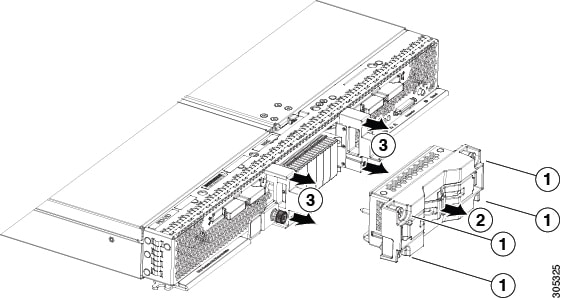
Completely loosen the captive screws on the front of the UCS Scalability Terminator. See callout 1 in the following figure.

Step 2

Open both ejector levers on the front of the UCS Scalability Terminator. See callout 2 in the following figure.

Step 3

While holding the ejector levers open, pull the UCS Scalability Terminator away from the blade server to separate it from the blade server. See callout 3 in the following figure.

Step 4

Once removed, place the UCS Scalability Terminator on an antistatic mat or antistatic foam.

Figure 1. Removing the Scalability Terminator


Installing a Scalability Connector

Use a UCS Scalability Connector to connect together two UCS Scalable M4 Blade Modules and form the UCS B460 M4 Blade Server.

Procedure


Step 1

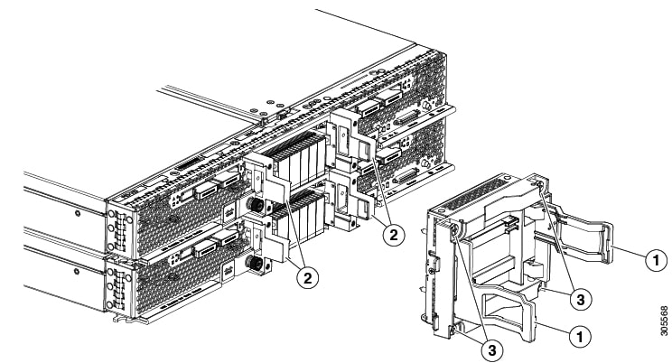
Open the ejector levers on the front of the UCS Scalability Connector. See callout 1 in the following figure.

Step 2

While holding the ejector levers open, line up the four guide posts with the holes on the bracket and push the UCS Scalability Connector into place until it engages. See callout 2.

Step 3

Close the ejector levers.

Step 4

Tighten the captive screws on the front of the UCS Scalability Connector. See callout 3.

Step 5

Use Cisco UCS Manager to power on the blade server and reconfigure it.

Figure 2. Installing the UCS Scalability Connector