Installing the Server Operating System or Hypervisor

Operating System or Hypervisor Installation Methods

The UCS E-Series M6 Servers support several operating systems and hypervisors. Regardless of the platform being installed, you can install it on your server using one of the following methods:

  • KVM console

  • PXE installation server

  • Host image mapping


Caution


You must use only one method to map virtual drives. For example, you must use either the KVM console or the Host Image Mapping method. Using a combination of methods will cause the server to be in an undefined state.


KVM Console

The KVM console is an interface accessible from the CIMC that emulates a direct keyboard, video, and mouse connection to the server. The KVM console allows you to connect to the server from a remote location. Instead of using CD/DVD or floppy drives physically connected to the server, the KVM console uses virtual media, which are actual disk drives or disk image files that are mapped to virtual CD/DVD. You can map any of the following to a virtual drive:

  • CD/DVD on your computer

  • Disk image files (ISO or IMG files) on your computer

  • USB flash drive on your computer

You can use the KVM console to install an operating system or hypervisor on the server and to do the following:

  • Access the BIOS setup menu by pressing F2 during bootup.

  • Access the CIMC Configuration Utility by pressing F8 during bootup.

Installing an Operating System or Hypervisor Using the KVM Console

Because the KVM console is operated only through the GUI, you cannot install an operating system or hypervisor using the CLI. To install a platform using the KVM console, follow the instructions in section Installing an Operating System or Hypervisor Using the KVM Console of the GUI Configuration Guide for Cisco UCS E-Series Servers and the Cisco UCS E-Series Network Compute Engine..

PXE Installation Servers

A Preboot Execution Environment (PXE) installation server allows a client to boot and install an operating system or hypervisor from a remote location. To use this method, a PXE environment must be configured and available on your VLAN, typically a dedicated provisioning VLAN. In addition, the server must be set to boot from the network. When the server boots, it sends a PXE request across the network. The PXE installationserver acknowledges the request and starts a sequence of events that installs the operating system or hypervisor on the server.

PXE servers can use installation disks, disk images, or scripts to install the operating system or hypervisor. Proprietary disk images can also be used to install the platform, additional components, or applications.


Note


PXE installation is an efficient method for installing a platform on a large number of servers. However, considering that this method requires setting up a PXE environment, it might be easier to use another installation method.


Installing an Operating System or Hypervisor Using a PXE Installation Server

Before you begin

Verify that the server can be reached over a VLAN.

Procedure


Step 1

Set the boot order to PXE.

For more information about setting the boot order, see section Configuring the Server Boot Order.

Step 2

Reboot the server.

Caution


If you are using the shared LOM interfaces to access CIMC, make sure that you do not use the CIMC GUI during the server reboot process. If you use the CIMC GUI, the GUI will disconnect during PXE installation as the boot agent overrides the IP address that was previously configured on the Ethernet ports.

If a PXE install server is available on the VLAN, the installation process begins when the server reboots. PXE installations are typically automated and require no additional user input. Refer to the installation guide for the operating system or hypervisor being installed to guide you through the rest of the installation process.


What to do next

After the installation is complete, reset the LAN boot order to its original setting.

Host Image Mapping

The Host Image Mapping feature allows you to download, map, unmap, or delete a host image. Download a host image, such as Linux, or VMware, from a remote FTP or HTTP server onto the CIMC internal repository, and then map the image onto the virtual drive of a USB controller in the E-Series M6 Servers. After you map the image, set the boot order to make the virtual drive, in which the image is mounted, as the first boot device, and then reboot the server. The host image must have .iso as the file extension.

Mapping the Host Image

Before you begin

  • Log in to the CIMC as a user with admin privileges.

  • Obtain the host image file from the appropriate third-party.


Note


If you start an image update while an update is already in process, both updates will fail.


Procedure

  Command or Action Purpose

Step 1

Server# scope host-image-mapping

Enters the remote install command mode.

Step 2

Server /host-image-mapping # download-image {ftp | ftps | http | https | scp} server-ip-address path / filename [username username password password]

Downloads the image from the specified remote server onto the CIMC internal repository. The host image must have .iso as the file extension. The remote server can be an FTP, FTPS, SCP, HTTP, or HTTPS server. If the remote server requires user authentication, you must add the username and password of the remote server.

Note


If the image file exceeds the size limit, an error message is displayed.

Note


The HTTP server does not support user authentication; only FTP supports user authentication.

Step 3

(Optional) Server /host-image-mapping # show detail

Displays the status of the image download.

Step 4

Server /host-image-mapping # map-image image_name.iso

Mounts the image on a virtual drive of the USB controller. The virtual drive can be one of the following:

  • HDD—Hard disk drive

  • CDROM—Bootable CD-ROM

Step 5

(Optional) Server /host-image-mapping # show detail

Displays the status of the host image mapping.

Example

This example shows how to maps the host image:

Server /host-image-mapping # download-image http 10.126.254.155 /download/image_name.iso
Username:
Password: 
Image download has started.
Please check the status using "show detail".
Current Mapped Image: None
Host Image Status: "Downloading ..Please wait: 8.1%"

Server /host-image-mapping # show detail
Current Mapped Image: None
Host Image Status: Image Downloaded and Processed Successfully
Server /host-image-mapping # map-image
Please check the status using "show detail".

Server /host-image-mapping # show detail
Current Mapped Image: image_name.iso
Host Image Status: Image mapped successfully, set HDD as the Boot device.
Server /host-image-mapping #

What to do next

  1. Set the boot order to make the virtual drive in which the image is installed as the first boot device. See section Configuring the Server Boot Order.

  2. Reboot the server. If the image contains an answer file, the operating system installation is automated and the image is installed. Otherwise, the installation wizard displays. Follow the wizard steps to install the image.

  3. If disk drives are not displayed after you install the operating system or hypervisor, you must install drivers. See section Firmware Management for details.

  4. After the installation is complete, reset the virtual media boot order to its original setting.

Unmapping the Host Image

Before you begin

Log in to the CIMC as a user with admin privileges.

Procedure

  Command or Action Purpose

Step 1

Server# scope host-image-mapping

Enters the remote install command mode.

Step 2

Server /host-image-mapping # unmap-image

Unmounts the image from the virtual drive of the USB controller.

Step 3

Server /host-image-mapping # show detail

(Optional) Displays the status of the host image unmapping.

Example

This example shows how to unmap the host image:

Server /host-image-mapping # unmap-image
Please check the status using "show detail".
Server /host-image-mapping # show detail
Current Mapped Image: None
Host Image Status: Unmap Successful!!
Server /host-image-mapping #

Deleting the Host Image

Before you begin

Log in to the CIMC as a user with admin privileges.

Procedure

  Command or Action Purpose

Step 1

Server# scope host-image-mapping

Enters remote install mode.

Step 2

Server /host-image-mapping # delete-image

Removes the image from the CIMC internal repository.

Example

This example deletes the host image:

Server# scope host-image-mapping
Server /host-image-mapping # delete-image

Configuring ESX Network Connectivity through MGF (TE1) Interface

On the E-Series M6 Servers, the MGF (TE1) interface connects internally to the Ethernet Switch Module through the backplane. This section explains how to set up a communication link between the UCS E-Series hosts with the external network.

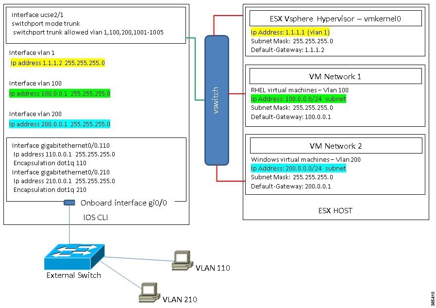
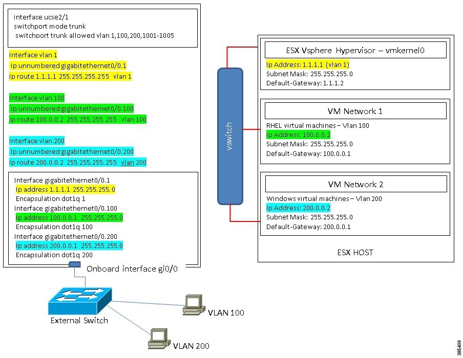
There are two scenarios where you can configure ESX Network Connectivity through the MGF (TE1) interface:

  • L2NETWORKING: Hosts and VMs in the Same Subnet.

  • L3 NETWORKING: Hosts and VMs in Different Networks

  • L3 NETWORKING: Hosts and VMs in the Same Network

L2 NETWORKING: Hosts and VMs in the Same Subnet

In this scenario, the UCS E-Series M6 Server is hosting the VMS in VLAN 100 and 200.The traffic enters the routerand passes through UCSE2/1/ GE1 interface and switches to the physical hosts by the EHWIC module.

L3 NETWORKING: Hosts and VMs in Different Network

In this scenario, the VMs communicate with hosts in different subnet by sending the traffic to the router throughthe UCSE1/0/1. On the router, the traffic hits the VLAN interface and gets L3 routed by the Catalyst 8300 Series Edge platform.

L3 NETWORKING: Hosts and VMs in the Same Network

In this scenario, the physical hosts are in the same subnet as the VMs. The physical hosts can be connected to the onboard L3 interface with the following configuration to enable the communication between the VMs and the physical hosts.