FlashStack with Cisco ACI Multi-Pod and Pure Storage ActiveCluster
Available Languages
FlashStack with Cisco ACI Multi-Pod and Pure Storage ActiveCluster
Design and Implementation Guide for FlashStack as a Stretched Data Center with vSphere 6.5 U1 using iSCSI
Last Updated: November 13, 2018

About the Cisco Validated Design Program
The Cisco Validated Design (CVD) program consists of systems and solutions designed, tested, and documented to facilitate faster, more reliable, and more predictable customer deployments. For more information, see:
http://www.cisco.com/go/designzone.
ALL DESIGNS, SPECIFICATIONS, STATEMENTS, INFORMATION, AND RECOMMENDATIONS (COLLECTIVELY, "DESIGNS") IN THIS MANUAL ARE PRESENTED "AS IS," WITH ALL FAULTS. CISCO AND ITS SUPPLIERS DISCLAIM ALL WARRANTIES, INCLUDING, WITHOUT LIMITATION, THE WARRANTY OF MERCHANTABILITY, FITNESS FOR A PARTICULAR PURPOSE AND NONINFRINGEMENT OR ARISING FROM A COURSE OF DEALING, USAGE, OR TRADE PRACTICE. IN NO EVENT SHALL CISCO OR ITS SUPPLIERS BE LIABLE FOR ANY INDIRECT, SPECIAL, CONSEQUENTIAL, OR INCIDENTAL DAMAGES, INCLUDING, WITHOUT LIMITATION, LOST PROFITS OR LOSS OR DAMAGE TO DATA ARISING OUT OF THE USE OR INABILITY TO USE THE DESIGNS, EVEN IF CISCO OR ITS SUPPLIERS HAVE BEEN ADVISED OF THE POSSIBILITY OF SUCH DAMAGES.
THE DESIGNS ARE SUBJECT TO CHANGE WITHOUT NOTICE. USERS ARE SOLELY RESPONSIBLE FOR THEIR APPLICATION OF THE DESIGNS. THE DESIGNS DO NOT CONSTITUTE THE TECHNICAL OR OTHER PROFESSIONAL ADVICE OF CISCO, ITS SUPPLIERS OR PARTNERS. USERS SHOULD CONSULT THEIR OWN TECHNICAL ADVISORS BEFORE IMPLEMENTING THE DESIGNS. RESULTS MAY VARY DEPENDING ON FACTORS NOT TESTED BY CISCO.
CCDE, CCENT, Cisco Eos, Cisco Lumin, Cisco Nexus, Cisco StadiumVision, Cisco TelePresence, Cisco WebEx, the Cisco logo, DCE, and Welcome to the Human Network are trademarks; Changing the Way We Work, Live, Play, and Learn and Cisco Store are service marks; and Access Registrar, Aironet, AsyncOS, Bringing the Meeting To You, Catalyst, CCDA, CCDP, CCIE, CCIP, CCNA, CCNP, CCSP, CCVP, Cisco, the Cisco Certified Internetwork Expert logo, Cisco IOS, Cisco Press, Cisco Systems, Cisco Systems Capital, the Cisco Systems logo, Cisco Unified Computing System (Cisco UCS), Cisco UCS B-Series Blade Servers, Cisco UCS C-Series Rack Servers, Cisco UCS S-Series Storage Servers, Cisco UCS Manager, Cisco UCS Management Software, Cisco Unified Fabric, Cisco Application Centric Infrastructure, Cisco Nexus 9000 Series, Cisco Nexus 7000 Series. Cisco Prime Data Center Network Manager, Cisco NX-OS Software, Cisco MDS Series, Cisco Unity, Collaboration Without Limitation, EtherFast, EtherSwitch, Event Center, Fast Step, Follow Me Browsing, FormShare, GigaDrive, HomeLink, Internet Quotient, IOS, iPhone, iQuick Study, LightStream, Linksys, MediaTone, MeetingPlace, MeetingPlace Chime Sound, MGX, Networkers, Networking Academy, Network Registrar, PCNow, PIX, PowerPanels, ProConnect, ScriptShare, SenderBase, SMARTnet, Spectrum Expert, StackWise, The Fastest Way to Increase Your Internet Quotient, TransPath, WebEx, and the WebEx logo are registered trademarks of Cisco Systems, Inc. and/or its affiliates in the United States and certain other countries.
All other trademarks mentioned in this document or website are the property of their respective owners. The use of the word partner does not imply a partnership relationship between Cisco and any other company. (0809R)
© 2018 Cisco Systems, Inc. All rights reserved.
Table of Contents
FlashStack with Application Centric Infrastructure
FlashStack with ACI as a Single Site
FlashStack with Cisco Multi-Pod ACI - Components
Non-Uniform and Uniform Storage Access
APIC Controller Considerations
Management Network and Mediator Access Requirements
Replication Network Requirements
FlashArray Replication Firewall Requirements
Deployment Hardware and Software
Cisco ACI Inter-Pod Deployment
Pure Storage ActiveCluster Configuration
Validated Hardware and Software
Bare-Metal Migration with FlashStack Multi-Pod and Cisco UCS Central
Reference Sources for this Design
Cisco Validated Designs consist of systems and solutions that are designed, tested, and documented to facilitate and improve customer deployments. These designs incorporate a wide range of technologies and products into a portfolio of solutions that have been developed to address the business needs of our customers.
This document discusses the design principles and implementation steps that go into the positioning of the FlashStack solution, which is a validated Converged Infrastructure (CI) jointly developed by Cisco and Pure Storage, as a stretched data center architecture supported across geographically displaced sites. The solution is a predesigned, using best-practices from both companies, utilizing VMware vSphere built on the Cisco Unified Computing System (Cisco UCS), Pure Storage FlashArray//X all flash array delivering iSCSI storage, and the Cisco Application Centric Infrastructure (ACI).
Implementation of the stretched data center architecture utilizes Cisco ACI Multi-Pod and Pure Storage ActiveCluster to extend both the network and storage between differing sites to be used by Cisco UCS compute to deliver a Virtual Server Infrastructure (VSI) design in this document, as well as a discussion of bare metal migration in the Appendix.
Introduction
In the current industry there is a trend for pre-engineered solutions which standardize the data center infrastructure, offering the business operational efficiencies, agility and scale to address cloud, bimodal IT and their business. This standardized data center needs to be seamless instead of siloed when spanning multiple sites, delivering a uniform network and storage experience to the compute and users accessing these data centers.
Cisco and Pure Storage have partnered together to create the FlashStack reference architecture, combining design best practices from both companies, along with detailed implementation examples of deploying the architecture. This FlashStack release delivers a unified data center through the use of Cisco ACI implementing the ACI Multi-Pod design along with synchronous replication of storage through Pure Storage ActiveCluster. With these technologies, customers will achieve consistency across differing sites, as well as a certain level of native business continuity, as production applications can run in any connected location regardless of the state of other sites.
Audience
The audience for this document includes, but is not limited to; sales engineers, field consultants, professional services, IT managers, partner engineers, and customers who want to take advantage of an infrastructure built to deliver IT efficiency and enable IT innovation.
Purpose of this Document
This document discusses the design features and decisions in bringing seamless connectivity between multiple FlashStack data center placements ranging from within a common data center, to crossing adjacent regions connecting multiple metropolitan locations. The components will be centered around the Cisco UCS 6332-16UP Fabric Interconnect and the Pure Storage FlashArray//X70, with the Spine and Leafs deployed as appropriate Cisco Nexus 9000 modular and fixed-port switches that were previously covered in the FlashStack with ACI single site CVD:
These are brought together as a cross site vSphere data center, delivering native levels of business continuity as well as an example of bare metal migration between sites that is discussed in the Appendix.
What’s New in this Release?
This FlashStack VSI design adds onto the previous single site FlashStack with ACI architecture with:
· Cisco ACI 3.2 implementing Multi-Pod
· Pure Storage Purity 5.0 implementing ActiveCluster
The combination of these powerful data center products allows secure layer 2 extension alongside layer 3 connectivity of the network in a solution the provides synchronous replication of data to be used within FlashStack VSI spanning multiple geographically displaced locations.
Solution Summary
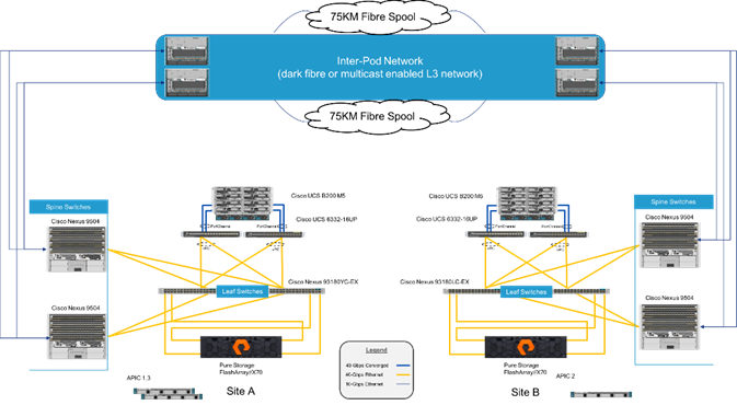
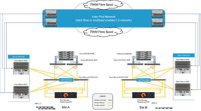
The FlashStack with Cisco ACI Multi-Pod and Pure Storage ActiveCluster is a validated design, built in a Cisco lab with the collaboration of Pure Storage. The design brings together two simulated FlashStack data centers that are connected through 75KM fibre spools to simulate connectivity between adjacent metropolitan regions, as shown in Figure 1.
Figure 1Physical Topology of the FlashStack with Multi-Pod Design
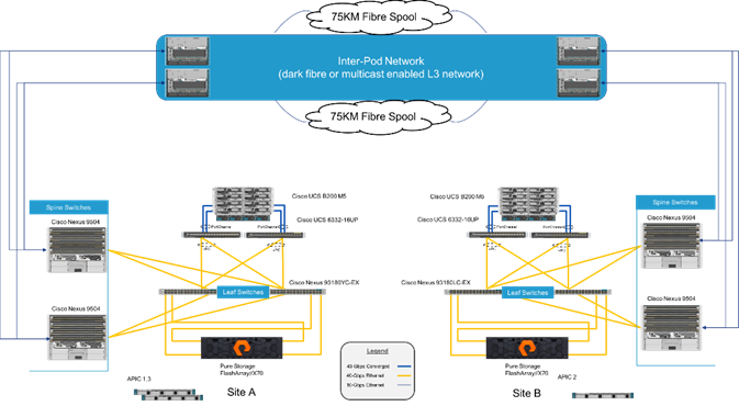
The hardware of this reference architecture was deployed with the following:
| Site A: |
Site B: |
| Pure Storage FlashArray//X70 |
Pure Storage FlashArray//X70 |
| Cisco UCS B200 M5 Blade Servers |
Cisco UCS B200 M5 Blade Servers |
| Cisco UCS 6332-16UP Fabric Interconnects |
Cisco UCS 6332-16UP Fabric Interconnects |
| Cisco ACI Application Policy Infrastructure Controllers |
Cisco ACI Application Policy Infrastructure Controller |
| Cisco Nexus 93180YC-EX Switches (Leaf) |
Cisco Nexus 93180LC-EX Switches (Leaf) |
| Cisco Nexus 9504 Switches (Spine) |
Cisco Nexus 9504 Switches (Spine) |
| Cisco Nexus 7504 Switches (Data Center Interconnect/ Existing Network connectivity as implemented for lab simulation) |
Cisco Nexus 7004 Switches (Data Center Interconnect/ Existing Network connectivity as implemented for lab simulation) |
![]() The 93180YC-EX Switches shown in Figure 1 can connect to the 6332-16UP Fabric Interconnects using its 40G uplink ports, but these ports will need to first be configured as downlink ports within the APIC.
The 93180YC-EX Switches shown in Figure 1 can connect to the 6332-16UP Fabric Interconnects using its 40G uplink ports, but these ports will need to first be configured as downlink ports within the APIC.
FlashStack System Overview
The FlashStack Virtual Server Infrastructure is a validated reference architecture, collaborated on by Cisco and Pure Storage, built to serve enterprise datacenters. The solution is built to deliver a VMware vSphere based environment, leveraging the Cisco Unified Computing System (Cisco UCS), Cisco ACI implemented with Cisco Nexus switches, and Pure Storage FlashArray as shown in Figure 2.
Figure 2FlashStack with ACI Components
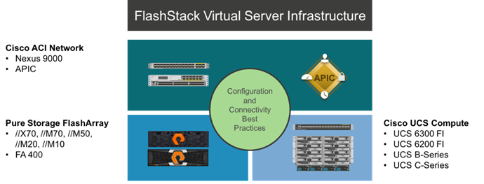
This design features a subset of the above components implemented with Cisco ACI. The compute is centered around the Cisco UCS 6332-16UP and the FlashArray//X or the FlashArray//M provide the capabilities of 40G or 10G iSCSI for storage communication. This managed compute and storage is delivered to Cisco UCS B200 M5 servers, with all of this extended to the network via a pair of Cisco Nexus 93180LC-EX switches configured within ACI as leaf switches to established Cisco Nexus 9504 spines.
FlashStack with Application Centric Infrastructure
The Cisco Nexus 9000 family of switches supports two modes of operation: NxOS standalone mode and Application Centric Infrastructure (ACI) fabric mode. In standalone mode, the switch performs as a typical Nexus switch with increased port density, low latency and 40G/100G connectivity. In fabric mode, the administrator can take advantage of Cisco ACI. Cisco Nexus 9000-based FlashStack design with Cisco ACI consists of Cisco Nexus 9500 and 9300 based spine/leaf switching architecture controlled using a cluster of three Application Policy Infrastructure Controllers (APICs).
Cisco ACI delivers a resilient fabric to satisfy today's dynamic applications. ACI leverages a network fabric that employs industry proven protocols coupled with innovative technologies to create a flexible, scalable, and highly available architecture of low-latency, high-bandwidth links. This fabric delivers application instantiations using profiles that house the requisite characteristics to enable end-to-end connectivity.
The ACI fabric is designed to support the industry trends of management automation, programmatic policies, and dynamic workload provisioning. The ACI fabric accomplishes this with a combination of hardware, policy-based control systems, and closely coupled software to provide advantages not possible in other architectures.
Cisco ACI Fabric
The Cisco ACI fabric consists of three major components:
· The Application Policy Infrastructure Controller (APIC)
· Spine switches
· Leaf switches
The ACI switching architecture is presented in a leaf-and-spine topology where every leaf connects to every spine using 40G Ethernet interface(s). The ACI Fabric Architecture is outlined in Figure 3.
Figure 3Cisco ACI Fabric Architecture
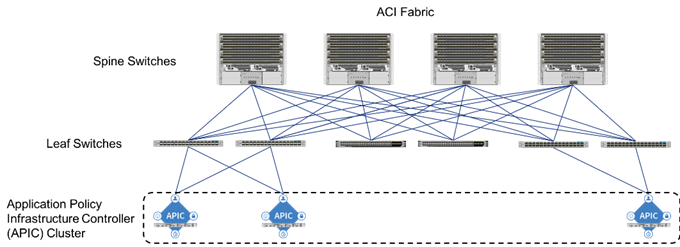
The software controller, APIC, is delivered as an appliance and three or more such appliances form a cluster for high availability and enhanced performance. APIC is responsible for all tasks enabling traffic transport including:
· Fabric activation
· Switch firmware management
· Network policy configuration and instantiation
Though the APIC acts as the centralized point of configuration for policy and network connectivity, it is never in line with the data path or the forwarding topology. The fabric can still forward traffic even when communication with the APIC is lost.
APIC provides both a command-line interface (CLI) and graphical-user interface (GUI) to configure and control the ACI fabric. APIC also exposes a northbound API through XML and JavaScript Object Notation (JSON) and an open source southbound API.
FlashStack with ACI as a Single Site
The FlashStack with ACI as a single site is designed to be fully redundant in the compute, network, and storage layers. There is no single point of failure from a device or traffic path perspective. Figure 4 shows how the various elements are connected together.
Figure 4FlashStack Single-Site Topology
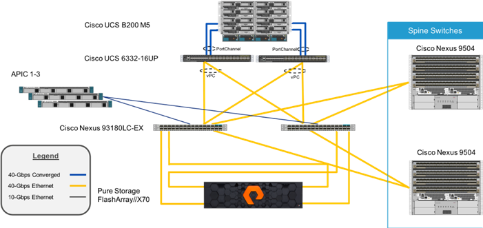
Fabric: Link aggregation technologies play an important role in FlashStack with ACI providing improved aggregate bandwidth and link resiliency across the solution stack. The Cisco Unified Computing System, and Cisco Nexus 9000 platforms support active port channeling using 802.3ad standard Link Aggregation Control Protocol (LACP). Port channeling is a link aggregation technique offering link fault tolerance and traffic distribution (load balancing) for improved aggregate bandwidth across member ports. In addition, the Cisco Nexus 9000 series features virtual Port Channel (vPC) capabilities. vPC allows links that are physically connected to two different Cisco Nexus 9000 Series devices to appear as a single "logical" port channel to a third device, essentially offering device fault tolerance. Note in the Figure above that vPC peer links are no longer needed. The peer link is handled in the leaf to spine connections and any two leaves in an ACI fabric can be paired in a vPC. The Cisco UCS Fabric Interconnects benefit from the Cisco Nexus vPC abstraction, gaining link and device resiliency as well as full utilization of a non-blocking Ethernet fabric. The FlashArray iSCSI ports connect into the Cisco Nexus 9000 and are independently reachable for each FlashArray controller interface configured as an iSCSI adapter.
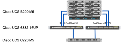
Compute: Each Cisco UCS 5108 chassis is connected to the FIs using a pair of ports from each IO Module for a combined 160G uplink as shown in Figure 5. Optional configurations could include Cisco UCS C-Series connected by directly attaching the Cisco UCS C-Series servers into the FIs to provide a uniform look and feel across blade and standalone servers within a common UCS Manager interface.
Figure 5FlashStack Compute Connectivity
![]() Cisco UCS C-Series servers are supported within FlashStack, but were not included as part of the validation associated with this CVD.
Cisco UCS C-Series servers are supported within FlashStack, but were not included as part of the validation associated with this CVD.
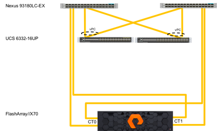
Storage: The ACI-based FlashStack design is an end-to-end IP-based storage solution that supports SAN access by using iSCSI. The solution provides a 10/40GbE fabric that is defined by Ethernet uplinks from the Cisco UCS Fabric Interconnects and Pure Storage FlashArrays connected to the Cisco Nexus switches as shown in Figure 6. Optionally, the ACI-based FlashStack design can be configured for SAN boot or application LUN access by using Fibre Channel (FC) by bringing Cisco MDS switches into the design to sit in parallel to the ACI network for single site and multi-site connectivity, but this is not covered in the design.
Figure 6FlashStack Storage Connectivity
The virtual environment this supports is within VMware vSphere 6.5 U1, and includes virtual management and automation components from Cisco and Pure Storage built into the solution, or as optional add-ons.
FlashStack with Cisco Multi-Pod ACI - Components
The Cisco ACI Multi-Pod design enables FlashStack to support multiple locations, is further enabled by Pure Storage ActiveCluster, allowing the cross-data center architecture to behave in much the same way as the FlashStack with ACI within a single site. These ACI pods at each site, are brought together by the Inter-Pod Network (IPN) of ACI, which can be interconnected by dedicated fiber, or multicast enabled L3 connectivity going over a provider network. This framework shown again in Figure 7 can provide a contiguous network between the sites that is further brought into the image of a single site by the synchronous replication of storage volumes achieved by Pure Storage ActiveCluster.
![]() The term “pod” will be used within this document to have differing meanings at times. ACI pods are sections of a distributed ACI fabric that are joined together by the IPN of ACI. Stretched pods are also referenced within ActiveCluster as collections of synchronously replicated volumes between configured FlashArrays.
The term “pod” will be used within this document to have differing meanings at times. ACI pods are sections of a distributed ACI fabric that are joined together by the IPN of ACI. Stretched pods are also referenced within ActiveCluster as collections of synchronously replicated volumes between configured FlashArrays.
Figure 7Physical Topology of the FlashStack with Multi-Pod Design
Cisco ACI Multi-Pod Network
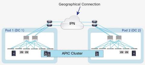
ACI Multi-Pod solution allows interconnecting and centrally managing ACI fabrics deployed in separate, geographically dispersed datacenters. In an ACI Multi-Pod solution, a single APIC cluster is deployed to manage all of the different ACI fabrics that are interconnected using an Inter-Pod Network (IPN) as shown in Figure 8. The separate ACI fabrics are named “Pods” and each of the pods looks like a regular two-tier spine-leaf fabric. A single APIC cluster can manage multiple Pods and various controller nodes that make up the cluster, can be deployed across these pods for resiliency. The deployment of Multi-Pod, as shown, meets the requirement of building Active/Active Data Centers, where different application components can be deployed across Pods.
Figure 8Cisco ACI Multi-Pod Design
Deploying a single APIC cluster simplifies the management and operational aspects of the solution as all the interconnected Pods essentially function as a single ACI fabric. The ACI configuration (VRFs, Bridge Domains, EPGs, etc.) and policies are made available across all the pods, providing a high degree of freedom for connecting endpoints to the fabric. Different workloads like web and application servers can be connected to or moved across different datacenter without having to re-provision or re-configure policies in various locations.
Multi-Pod configuration offers failure domain isolation across Pods through separation of the fabric control plane protocols. Different instances of IS-IS, COOP and MP-BGP protocols run inside each pod therefore faults and issues from one pod are contained within the pod and not spread across the entire Multi-Pod fabric.
Inter-Pod Network
Different pods (datacenters) in a Multi-Pod environment are interconnected using an Inter-Pod Network (IPN). Each pod connects to the IPN through the spine nodes. The IPN is provides basic Layer 3 connectivity allowing establishment of spine to spine and leaf to leaf VXLAN tunnels across the datacenters. The IPN device can be any device that can support:
· A routing protocol such as OSPF
· PIM bi-dir configuration for broadcast, unknown unicast and multicast (BUM) traffic
· DHCP relay functionality to allow auto-provisioning of ACI devices across the pods
· Increased MTU (9150 bytes or more) for handling VxLAN overhead across the pods
For more information about Multi-Pod design and setup, visit: https://www.cisco.com/c/en/us/solutions/collateral/data-center-virtualization/application-centric-infrastructure/white-paper-c11-737855.html
Pure Storage Active Cluster
Pure Storage® Purity ActiveCluster is a fully symmetric active/active bidirectional replication solution that provides synchronous replication for RPO zero and automatic transparent failover for RTO zero. ActiveCluster spans multiple sites enabling clustered arrays and clustered hosts to be used to deploy flexible active/active datacenter configurations.
Figure 9ActiveCluster Overview
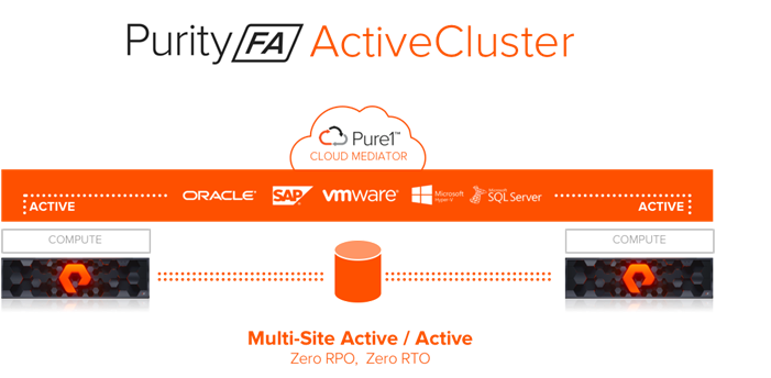
Synchronous Replication - Writes are synchronized between arrays and protected in non-volatile RAM (NVRAM) on both arrays before being acknowledged to the host.
Symmetric Active/Active - Read and write to the same volumes at either side of the mirror, with optional host-to-array site awareness.
Transparent Failover - Automatic Non-disruptive failover between synchronously replicating arrays and sites with automatic resynchronization and recovery.
Async Replication Integration - Uses async for baseline copies and resynchronizing. Convert async relationships to sync without resending data. Async data to a 3rd site for DR.
Integrated Pure1® Cloud Mediator - Automatically configured passive mediator that allows transparent failover and prevents split-brain, without the need to deploy and manage another component.
Components
Purity ActiveCluster is composed of three core components: The Pure1 Mediator, active/active clustered array pairs, and stretched storage containers.
Figure 10 ActiveCluster Components
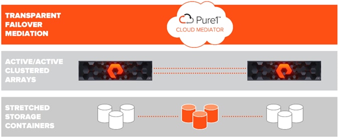
The Pure1 Cloud Mediator - A required component of the solution that is used to determine which array will continue data services should an outage occur in the environment.
Active/Active Clustered FlashArrays - Utilize synchronous replication to maintain a copy of data on each array and present those as one consistent copy to hosts that are attached to either, or both, arrays.
Stretched Storage Containers - Management containers that collect storage objects such as volumes into groups that are stretched between two arrays.
Administration
ActiveCluster introduces a new management object within FlashArray: Pods. A pod is a stretched storage container that defines a set of objects that are synchronously replicated together, and which arrays they are replicated between. An array can support multiple pods. Pods can exist on just one array or on two arrays simultaneously with synchronous replication. Pods that are synchronously replicated between two arrays are said to be stretched between arrays.
Figure 11 FlashArrays with Stretched and Non-Stretched Pods
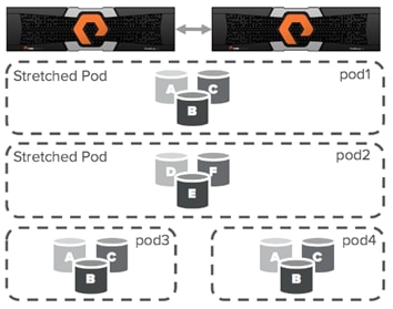
Pods can contain volumes, protection groups (for snapshot scheduling and asynchronous replication) and other configuration information such as which volumes are connected to which hosts. The pod acts as a consistency group, ensuring that multiple volumes within the same pod remain write order consistent.
Pods also provide volume namespaces, that is different volumes may have the same volume name if they are in different pods. In the image above the volumes in pod3 and pod 4 are different volumes than those in pod1, a stretched active/active pod. This allows migration of workloads between arrays or consolidation of workloads from multiple arrays to one, without volume name conflicts.
Mediator
Transparent failover between arrays in ActiveCluster is automatic and requires no intervention from the storage administrator. Failover occurs within standard host I/O timeouts similar to the way failover occurs between two controllers in one array during non-disruptive hardware or software upgrades.
The Pure1® Cloud Mediator
A failover mediator must be located in a 3rd site that is in a separate failure domain from either site where the arrays are located. Each array site must have independent network connectivity to the mediator such that a single network outage does not prevent both arrays from accessing the mediator. A mediator should also provide a very lightweight and easy to administer component of the solution. The default Pure ActiveCluster solution automatically leverages an integrated cloud-based mediator service.
The mediator provides two main functions:
1. Prevent a split-brain condition from occurring where both arrays are independently allowing access to data without synchronization between arrays.
2. Determine which array will continue to service IO to synchronously replicated volumes in the event of an array failure, replication link outage, or site outage.
On-Premises Failover Mediator
Failover mediation for ActiveCluster can also be provided using an on-premises mediator distributed as an OVF file and deployed as a VM. Failover behaviors are exactly the same as described above. The on-premises mediator simply replaces the role of the Pure1 Cloud Mediator during failover events.
Non-Uniform and Uniform Storage Access
ActiveCluster supports hosts connected to one or both FlashArrays. Hosts that are connected to both FlashArrays are described as having uniform access to storage. Hosts connected to one of the two flash arrays are described as having non-uniform access to storage.
Non-Uniform Storage Access
A non-uniform storage access model is used in environments where there is host-to-array connectivity of either FC or Ethernet (for iSCSI) only locally within the same site. Ethernet connectivity for the array-to-array replication interconnect must still exist between the two sites. When deployed in this way each host has access to a volume only through the local array and not the remote array. The solution supports connecting arrays with up to 5ms of round trip time (RTT) latency between the arrays.
Figure 12 ActiveCluster Providing Non-Uniform Storage Access to Hosts

![]() Hosts will distribute I/Os across all paths to the storage only, because only the local Active/Optimized paths are available.
Hosts will distribute I/Os across all paths to the storage only, because only the local Active/Optimized paths are available.
Uniform Storage Access
A uniform storage access model can be used in environments where there is host-to-array connectivity of either FC or Ethernet (for iSCSI), and array-to-array Ethernet connectivity, between the two sites. When deployed in this way a host has access to the same volume through both the local array and the remote array. The solution supports connecting arrays with up to 5ms of round trip time (RTT) latency between the arrays.
Figure 13 ActiveCluster Providing Uniform Storage Access to Hosts

The image above represents the logical paths that exist between the hosts and arrays, and the replication connection between the two arrays in a uniform access model. Because a uniform storage access model allows all hosts, regardless of site location, to access both arrays there will be paths with different latency characteristics. Paths from hosts to the local array will have lower latency; paths from each local host to the remote array will have higher latency.
For the best performance in an active/active synchronous replication environments hosts should be prevented from using paths that access the remote array unless necessary. For example; in the image below if VM 2A were to perform a write to volume A over the host side connection to array A, that write would incur 2X the latency of the inter-site link, 1X for each traverse of the network. The write would experience 5ms of latency for the trip from host B to array A and experience another 5ms of latency while array A synchronously sends the write back to array B.
Figure 14 Logical Paths for VMs Between Sites
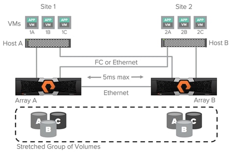
With Pure Storage Purity ActiveCluster there are no such management headaches. ActiveCluster does make use of ALUA to expose paths to local hosts as active/optimized paths and expose paths to remote hosts as active/non-optimized. However, there are two advantages in the ActiveCluster implementation:
1. In ActiveCluster volumes in stretched pods are read/write on both arrays.
![]() There is no such thing as a passive volume that cannot service both reads and writes.
There is no such thing as a passive volume that cannot service both reads and writes.
2. The optimized path is defined on a per host-to-volume connection basis using a preferred-array option; this ensures that regardless of what host a VM or application is running on it will have a local optimized path to that volume.
Figure 15 Optimized vs. Non-Optimized Paths in ActiveCluster
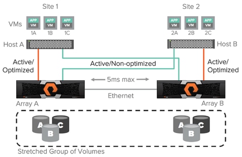
ActiveCluster enables truly active/active datacenters and removes the concern around what site or host a VM runs on; the VM will always have the same performance regardless of site. While a VM 1A is running on host A accessing volume A it will use only the local optimized paths as shown in Figure 16.
Figure 16 Performance Assured with Optimized Paths
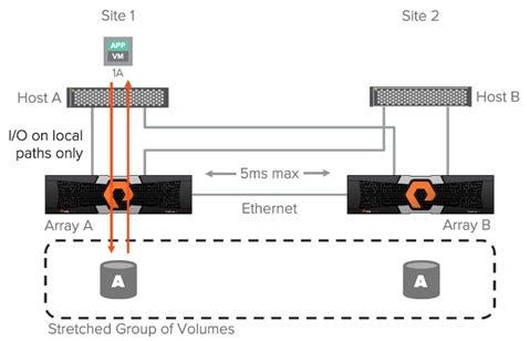
If the VM or application is switched to a host in the other site, with the data left in place, only local paths will be used in the other site as shown in the next image. There is no need to adjust path priorities or migrate the data to a different volume to ensure local optimized access.
Cisco Umbrella (optional)
Cisco Umbrella is the delivery of secure DNS through Cisco’s acquisition of OpenDNS. Umbrella stops malware before it can get a foothold by using predictive intelligence to identify threats that next-generation firewalls might miss. Implementation is easy as pointing to Umbrella DNS servers, and unobtrusive to the user base outside of identified threat locations they may have been steered to. In addition to threat prevention, Umbrella provides detailed traffic utilization as shown in Figure 17.
Figure 17 Traffic Breakdown of Activity Seen Through Umbrella

Cisco Intersight (optional)
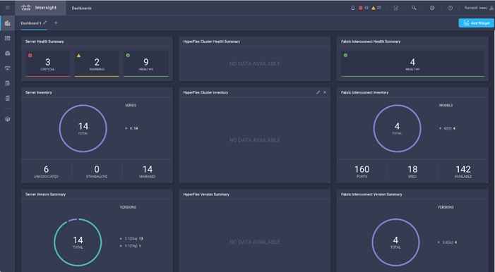
Cisco Intersight gives IT operations management to claimed devices across differing sites, presenting these devices within a unified dashboard. The adaptive management of Intersight provides visibility and alerts to firmware management, showing compliance across managed UCS domains, as well as proactive alerts for upgrade recommendations. Integration with Cisco TAC allows the automated generation and upload of tech support files from the customer.
Figure 18 Cisco Intersight Dashboard
Cisco UCS Central (optional)
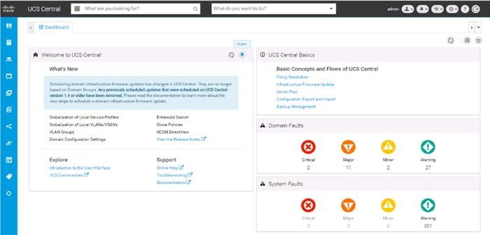
Cisco UCS Central creates administrative visibility and control of multiple UCS domains across common or connected sites. The visibility shows a common dashboard for all connected UCS domains indicating issues at any site, allowing quick access to these UCS domains, either to the respective Cisco UCS Fabric Interconnects, or to the Cisco UCS KVM consoles of associated Service Profiles. The control aspect gives uniformity to policy implemented through Service Profiles and Service Profile Templates implemented globally from Cisco UCS, or from the local Cisco UCS Fabric Interconnect, drawing upon those policies centrally managed by Cisco UCS Central.
Figure 19 Cisco UCS Central Dashboard
Requirements
Each site will need to have a FlashStack deployed following the steps detailed in the previous FlashStack with ACI Design and Implementation Guide.
· You will need to physically setup two sites according to the FlashStack with ACI DIG
· You will need to configure one of the two sites using the FlashStack with ACI DIG (the primary site)
· You will need to follow the Multi-Pod configuration section below to configure the IPN and the Spines/Leaf Switches in the second site.
· When the ACI fabric is setup/extended to the second site, we can use the FlashStack/ACI DIG to complete the compute and storage configuration
These sites will need to be connected by fibre or a multicast enabled L3 network, and conform to the following requirements:
· Less than 5ms RTT for ActiveCluster communication (Multi-Pod communication can support up to 10ms RTT if synchronous storage is not a requirement).
· Identical models of FlashArrays at each site.
· Processor compatibility between UCS servers across the differing sites to be able to support vMotion across sites (optionally configure vSphere EVC if there is a disparity).
Physical Topology
Figure 20 Physical Topology of FlashStack with Multi-Pod Design

Logical Topology
With the Multi-Pod connectivity in place, there are three main traffic types that are served by the Inter-Pod Network, connecting the fabric spanning the two sites above.
· Compute Data Traffic
· Storage Traffic (iSCSI)
· ActiveCluster Traffic
Figure 21 Compute Data Traffic across FlashStack with Multi-Pod
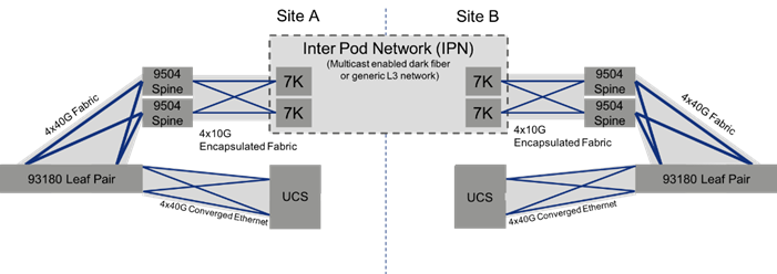
The compute connectivity within the configured FlashStack environments, utilize high bandwidth 40G connections, as shown in Figure 21. Each step within the validated architecture is set for redundancy in the device and link level. As an option, a lower bandwidth 10G equivalent architecture may be sufficient if it meets the needs of the applications hosted by the infrastructure.
The connectivity bandwidth of the environment will drop down as it approaches the IPN for connections coming from the ACI spines to the IPN, as IPN connected networks will in most cases be of lower capacity than the data center network.
The following compute data traffic patterns are to be expected within a single EPG (assumes common port group in virtual switch):
· VM traffic within the same host will not leave the host.
· VM traffic across hosts within the same UCS domain, for traffic pinned within the same fabric interconnect (pictured as part of the logical unit of Cisco UCS above) will not make it up to the ACI fabric, and will resolve within the UCS layer.
· VM traffic across hosts within the same UCS domain, for traffic pinned between differing fabric interconnects, but connecting up into the same ACI leaf will be switched locally as the same VLAN.
· VM traffic across hosts within the same UCS domain, for traffic pinned between differing fabric interconnects, pathing to differing fabric leafs within the pair, will be encapsulated into a VXLAN packet and sent up through the upstream fabric spine to be passed onto the sibling leaf for de-encapsulation before transmission to the appropriate fabric interconnect.
· VM traffic across hosts residing in differing UCS domains residing on differing sides of the IPN will follow the same steps up to the ACI spine as the previous situation, but will follow the fabric over the IPN and de-encapsulate once it reaches the remote ACI leaf in which the host is associated.
![]() A detailed breakdown of packet flow within the ACI fabric can be found here: https://www.cisco.com/c/en/us/support/docs/switches/nexus-9336pq-aci-spine-switch/118930-technote-aci-00.html
A detailed breakdown of packet flow within the ACI fabric can be found here: https://www.cisco.com/c/en/us/support/docs/switches/nexus-9336pq-aci-spine-switch/118930-technote-aci-00.html
Figure 22 Storage Traffic Across FlashStack with Multi-Pod
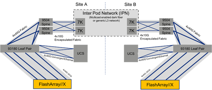
The storage traffic within the FlashStack, shown in Figure 22 above, is split between A and B iSCSI networks that will be handled in a similar manner to the compute data traffic. The FlashArray will communicate through the ACI leaf to get to either the local UCS or through the IPN if the normal preferred path is not available, or if a volume associated to a remote FlashArray is not stretched to the local FlashArray.
Figure 23 ActiveCluster Traffic Across FlashStack with Multi-Pod
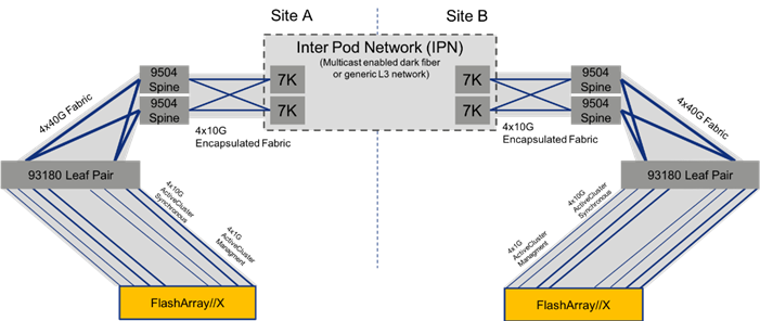
The ActiveCluster specific traffic, shown in Figure 23, is between the two FlashArrays and the mediator (not pictured.) The synchronous information is passed along 4x10G connections, along with 4x1G management connections that are used as control elements. Both pass through the respective ACI leaf and spine pairs specific to their local site, and are connected by the IPN treated along those paths in the same way as compute and storage traffic.
Management Network Considerations
The management networks used for virtualization between the two sites will be configured in what can be summarized as either a Brown Field scenario (integrating with existing infrastructure), or Green Field scenario (new placement originating from the ACI fabric).
Figure 24 Brown Field Management Source External to the ACI Fabric

The Brown Field situation was configured in the previous single site FlashStack with ACI design. The management network, referred to as an IB-Mgmt in the CVD, came in from an external switch and routing for that network was managed by a router upstream of that switch. Continuation of a Brown Field model can occur, but some routing will need to be worked out external to the fabric if this implementation persists as traffic will need to traverse cross site. In this model, the management network that the vCenter is configured on will need to be pulled over to the other site by associating the secondary site Cisco UCS within that EPG, and configuring the extended management network in the vSphere hosts.
Figure 25 Green Field Management from the ACI Fabric

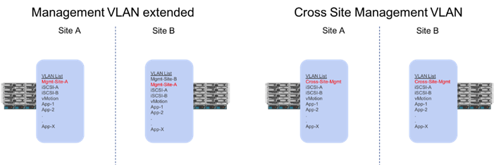
A single unified Cross-Site-Mgmt EPG as pictured in Figure 25, will provide the default connectivity needed for vCenter and other management VMs to exist within either site. As an option, site specific management that is configured within, or ported into the ACI fabric can valid. If site specific management is created or ported into the ACI fabric, it will need have one of the management EPGs extended as was mentioned previously.
These management networks will be the only potential differences in the UCS deployments between the two sites. This management network extended across the sites will be configured as one of the options shown in Figure 26 below.
Figure 26 Cisco UCS Management Networks Between Sites
ACI Multi-Pod Design
The ACI Multi-Pod design used in this CVD is shown in Figure 27.
Figure 27 High Level Multi-Pod Design

IPN Configuration
The Inter-Pod Network consists of two Nexus 7004 switches in each datacenter connected using a 10Gbps 75 km long fiber. The dual link design provides high availability in case of a link failure. Each spine is connected to each of the Nexus 7004s using a 10Gbps connection for a fully redundant setup.
Each Nexus 7004 is configured for the following features to support the Multi-Pod network:
PIM Bidir Configuration
In addition to unicast communication, Layer 2 multi-destination flows belonging to bridge domains that are extended across Pods must also be supported. This type of traffic is usually referred to as Broadcast, Unknown Unicast and Multicast (BUM) traffic and it is exchanged by leveraging VXLAN data plane encapsulation between leaf nodes. Inside a Pod (or ACI fabric), BUM traffic is encapsulated into a VXLAN multicast frame and it is always transmitted to all the local leaf nodes. In order to flood the BUM traffic across Pods, the same multicast used inside the Pod is also extended through the IPN network. PIM bidir enables this functionality on the IPN devices.
OSPF Configuration
OSPF is enabled on Spine switches and IPN devices to exchange routing information between the Spine switches and IPN devices.
DHCP Relay Configuration
In order to support auto-provisioning of configuration for all the ACI devices across multiple Pods, the IPN devices connected to the spines must be able to relay DHCP requests generated from ACI devices in remote Pods toward the APIC node(s) active in the first Pod.
Interface VLAN Encapsulation
The IPN device interfaces connecting to the ACI Spines are configured as sun-interfaces with VLAN encapsulation value set to 4.
MTU Configuration
The IPN devices are configured for maximum supported MTU value of 9216 to handle the VxLAN overhead.
TEP Pools and Interfaces
In Cisco ACI Multi-Pod setup, unique Tunnel Endpoint (TEP) Pools are defined on each site. In this CVD, these pools are 10.11.0.0/16 and 10.12.0.0/16 for the two datacenters.
External TEP
The pod connection profile uses a VXLAN TEP (VTEP) address called the External TEP (ETEP) as the anycast shared address across all spine switches in a pod. This IP address should not be part of the TEP pool assigned to each pod and is therefore selected outside the two networks listed above. The IP addresses used in the two datacenters are 10.241.249.1 and 10.242.249.1.
APIC Controller Considerations
The ACI Multi-Pod fabric brings interesting considerations for the deployment of the APIC controller cluster managing the solution. To increase the scalability and resiliency of the design, APIC supports data sharding for data stored in the APIC. The basic idea behind sharding is that the data repository is split into several database units, known as ‘shards’ and the shard is then replicated three times, with each copy assigned to a specific APIC appliance. In a three node APIC cluster, one replica of each shard exists on every node. In this scenario, if two of the three nodes become unavailable, the shards in third node become read-only because of lack of quorum and stay in read-only mode until the other nodes become accessible again.
Figure 28 APIC Nodes and Data Sharding
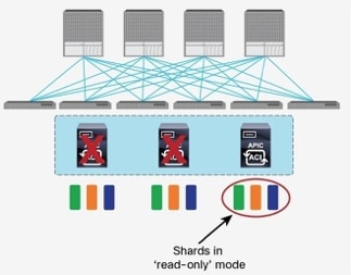
In Figure 28, the three APIC nodes are distributed across the two datacenters. In case of a split-brain scenario where two datacenters cannot communicate to each other over the IPN, this implies that the shards on the APIC nodes in Pod1 would remain in full ‘read-write’ mode, allowing a user connected there to make configuration changes however the shards in Pod2 will move to a ‘read-only’ mode. Once the connectivity issues are resolved and the two Pods regain full connectivity, the APIC cluster would come back together and any change made to the shards in majority mode would be applied also to the rejoining APIC nodes.
To mitigate this scenario, customers can deploy a 3 nodes APIC cluster with two nodes in Pod1 and one node in Pod2 and then add a fourth backup APIC node in Pod2 to handle the full site failure scenario. The backup APIC server however should only be brought into action if a long-term connectivity outage or datacenter maintenance is expected. For typical short-term outages, three node cluster should suffice in most scenarios.
For more information about APIC cluster and sizing recommendations, consult the Multi-Pod design white paper: https://www.cisco.com/c/en/us/solutions/collateral/data-center-virtualization/application-centric-infrastructure/white-paper-c11-737855.html
Storage Design
The FlashStack Multi-Pod design utilizes iSCSI for storage networking. Within the implementation of iSCSI, the traditional best practices still apply: crossed connections from each controller through two fabrics. Fibre Channel networking is not included as an option in this design, as it would require a completely independent Fibre Channel and or FCoE network between the sites for carrying the storage traffic.
This design configures a uniform environment for the hosts accessing potentially long-distance connections between arrays. Within these long distances separating the arrays, it’s important to emphasize that redundant paths are still important for long distance connections as the Multi-Pod IPN network is traversed.
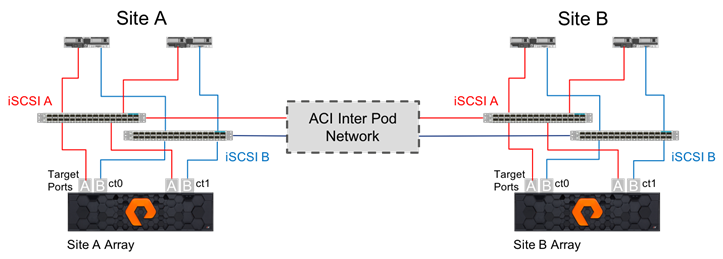
Uniform Storage Configuration is established for each iSCSI network carried through the Inter Pod Network as shown in Figure 29.
Figure 29 Uniform Storage within the Multi-Pod Deployment
Management Network and Mediator Access Requirements
Due to the introduction of the Mediator for ActiveCluster, a fully redundant network configuration is required for eth0 and eth1 management interfaces which includes cross connectivity to multiple switches shown in Figure 30 below. This configuration insures that any single network failure does not prevent the array from contacting the mediator in the event of a significant failure at the remote site.
Figure 30 Redundant Management Interfaces Configured for ActiveCluster
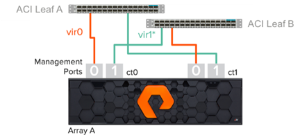
· Use both management ports so each controller is resilient to unexpected management network incidents
· Connect each management port to 1 of 2 network switches
· Verify that eth0 connects to Switch A and eth1 connects to Switch B on CT0. On CT1 verify that eth0 connects to Switch B and eth1 connects to Switch A.
Replication Network Requirements
The replication network is used for the initial asynchronous transfer of data to stretch a pod, to synchronously transfer data and configuration information between the arrays, and to resynchronize a pod.
· 5ms maximum round trip latency between arrays for ActiveCluster
· Adequate bandwidth between arrays to support bi-directional synchronous writes and bandwidth for resynchronizing. This depends on the write rate of the hosts at both sites.
· 10Gb twinax or optical cabling for four replication interfaces per array
· Four IP addresses per array, one for each array replication interface
· Arrays cannot be directly connected, switching is required between arrays
· The default MTU is 1500 (adjusted to 9000 in FlashStack)
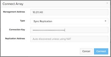
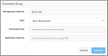
· When connecting a remote array for replication, the replication addresses are auto-discovered. You only need to enter the Replication Addresses when the remote array's replication addresses are being translated via Network Address Translation (NAT), in which case you must enter all the external NAT addresses here.
FlashArray Replication Firewall Requirements
In order to replicate between two FlashArrays, the arrays must be able to communicate via the following ports:
| Service/Port Type |
Firewall Port |
| Management ports |
443 |
| Replication Ports |
8117 |
Replication Network Topology
ActiveCluster requires that every replication port on one array has network access to every replication port on the other array. This can be done by ensuring that redundant switches are interconnected, by routing, or by ensuring that the long-distance Ethernet infrastructure allows a switch in one site to connect to both switches in the other site.
Figure 31 Redundant Connectivity for the Replication Ports in ActiveCluster
Virtualization Design
vCenter
For the hypervisor environment, a common vCenter is used to manage an ESXi cluster spanning both sites. If the vCenter is to have increased availability through vSphere HA, extending through both sites, it will need to be hosted within the FlashStack and have a cross site management network that it is placed in, (as was covered in the previous UCS design section). If the vCenter sits outside of FlashStack environment, availability in site impact scenarios may need to be worked out with implementing vCenter HA (not covered in this document).
Virtual Switching
The port groups for tenant applications, vMotion, iSCSI, and potentially management networks will be common to both sites, whether they are managed by a manually created vSwitch/vDS, or implemented by the Virtual Machine Manager (VMM). The VMM association is created for the first site placement of FlashStack within APIC, creating a vDS within the vCenter that has port groups associated to VLANs from a dynamic pool that is configured within the APIC and carried within the appropriate UCS vNICs on both sites. The connectivity for vMotion, iSCSI, and a potential management network will all have been created as respective EPGs during the setup of the first site, those EPGs will be joined by the UCS connectivity of the second site as static ports, automatically enabling L2 extension for that traffic.
VM Mobility and Availability
With uniform storage access configured for the hosts, vMotion, DRS, and HA are all options within the vSphere environment for the cluster spanning the two sites, shown in Figure 32.
Figure 32 vSphere Environment Across the Two Sites
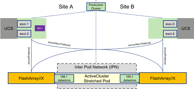
vMotion between these sites can be performed at will as the port groups for the VMs are available across all hosts, and the ActiveCluster stretched datastores are active/active and synchronously replicated across both sites. In the event of a catastrophic fault to the just the FlashArray on one site, VMs in place for that site will continue operating as shown in Figure 33.
Figure 33 vMotion After a Storage Failure
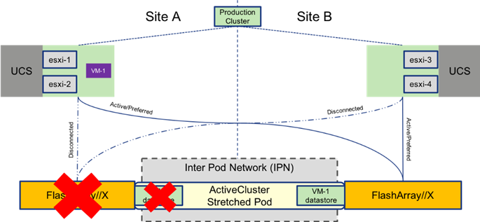
Figure 34 VM Moved by vMotion to Second Site
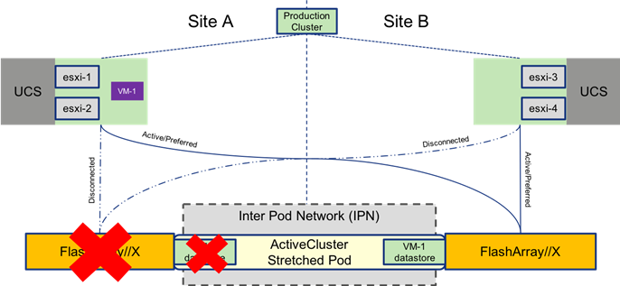
The VM is moved by vMotion to the site holding the storage to which it is connected and return to normal operational performance with host and storage local to the VM as shown in Figure 35.

With vSphere HA configured, site availability can be delivered for resources protected by the FlashStack. Normal HA rules will apply in the event of a complete site/datacenter down situation as shown in Figure 36.
Figure 36 HA Event for a FlashStack in Multi-Pod
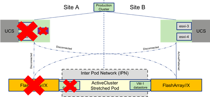
After the hosts are identified to be down by the HA rules configured within the cluster, VMs are restarted on available hosts on the other site (approximately one minute).
Figure 37 VM brought up through HA Event
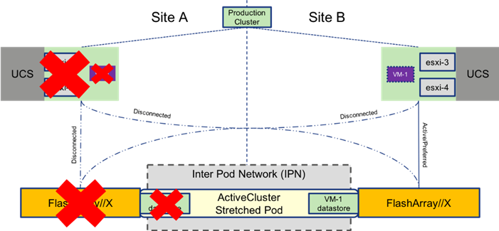
General vSphere HA configuration guidelines will apply across the overall cluster, and admission control as well as heartbeat datastores should be configured according to the customer’s own expectations for these rules.
Architecture
The design, shown in Figure 38, brings network uniformity across data center environments through Cisco ACI Multi-Pod, along with storage availability through Pure Storage ActiveCluster, which combined together deliver portability within a configured vSphere environment of the FlashStack.
Figure 38 Physical Topology of the FlashStack with Multi-Pod Design
Deployment
The FlashStack converged infrastructure (CI) should be deployed for the primary site, following the instructions found in the FlashStack Virtual Server Infrastructure with Cisco Application Centric Infrastructure and Pure Storage FlashArray CVD:
Example networks used during the lab validation between the two sites are listed in Table 1.
| Site A |
Site B |
||||
| Name |
VLAN |
Subnet |
Name |
VLAN |
Subnet |
| IB-Mgmt-Site-A |
215 |
10.2.164.0/24 |
IB-Mgmt-Site-B |
115 |
10.1.164.0/24 |
| Native-VLAN |
2 |
N/A |
Native-VLAN |
2 |
N/A |
| CrossSite-Mgmt(1) |
116 |
10.6.164.0/24 |
CrossSite-Mgmt(2) |
116 |
10.6.164.0/24 |
| vMotion |
110 |
192.168.110.0/24 |
vMotion |
110 |
192.168.110.0/24 |
| iSCSI-A-VLAN |
101 |
192.168.101.0/24 |
iSCSI-A-VLAN |
101 |
192.168.101.0/24 |
| iSCSI-B-VLAN |
102 |
192.168.102.0/24 |
iSCSI-B-VLAN |
102 |
192.168.102.0/24 |
| VM-App-[2201-2220] |
2201-2220 |
As allocated by the customer |
VM-App-[2201-2220] |
2201-2220 |
As allocated by the customer |
(1) Replace with IB-Mgmt-Site-B if extending IB-Mgmt-Site-B network for vCenter/Management VMs.
(2) Replace with IB-Mgmt-Site-A if extending IB-Mgmt-Site-A network for vCenter/Management VMs.
![]() Site specific management networks versus a dedicated cross site management network should be used as appropriate to the deployment.
Site specific management networks versus a dedicated cross site management network should be used as appropriate to the deployment.
The FlashStack CI for the secondary site can be deployed for the compute (Cisco UCS) and storage (Pure Storage FlashArray//X) following the same previous CVD instructions followed for the primary site. The virtualization instructions should be followed for the secondary site, but will ignore the setting up of another vCenter.
Cisco UCS Deployment
There are no Cisco UCS deployment steps specific to the FlashStack with Multi-Pod deployment outside of the handling of the management or IB-Mgmt VLAN that will differ from the FlashStack with ACI single site deployment CVD listed previously.
Configuring the CrossSite-Mgmt VLAN or the extended VLAN of either IB-Mgmt-Site-A or IB-Mgmt-Site-B will need to be added within Cisco UCS Manager under:
LAN -> LAN Cloud -> VLANs -> Create VLANs operation
With this VLAN created, it will additionally be added within Cisco UCS Manager to:
LAN -> Policies -> root (or appropriate org) -> vNIC Templates -> vNIC Template vNIC_Mgmt_A
Cisco ACI Inter-Pod Deployment
In order to deploy an ACI Multi-Pod network, single site ACI configuration should already be in place. In this CVD, Pod1 has already been configured as a single-site FlashStack environment. The following tasks will walk you through the set up:
1. IPN device configurations in both Site 1 and Site 2
2. Spines configuration on Site 1
3. Multi-Pod configuration
4. Spines and Leaves discovery on Site 2 (new site)
5. Setting up Spines configuration on Site 2 to complete the Multi-Pod setup
Refer to Figure 39 for details about various device links and associated IP addresses and subnets used in the following configurations.
Figure 39 IPN and Spine Connectivity
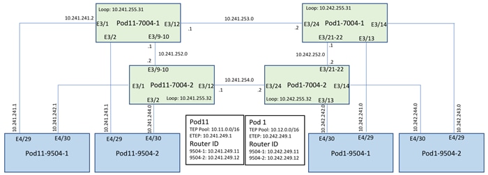
IPN Device Configurations
The following shows the relevant configurations of the four IPN devices. The configuration enables multicast, OSPF, jumbo MTU and DHCP relay on all the IPN devices. The configuration below uses a single IPN device as RP for PIM bidir traffic. In a production network, deploying a phantom RP for high availability is recommended: https://www.cisco.com/c/dam/en/us/products/collateral/ios-nx-os-software/multicast-enterprise/prod_white_paper0900aecd80310db2.pdf.
Pod 1 7004-1
feature ospf
feature pim
feature lacp
feature dhcp
feature lldp
!
! Define the multicast groups and associated RP addresses
!
ip pim rp-address 10.241.255.1 group-list 225.0.0.0/8 bidir
ip pim rp-address 10.241.255.1 group-list 239.0.0.0/8 bidir
ip pim ssm range 232.0.0.0/8
!
service dhcp
ip dhcp relay
!
interface port-channel1
description To Pod 1 7004-2
mtu 9216
ip address 10.242.252.1/30
ip ospf network point-to-point
ip ospf mtu-ignore
ip router ospf 10 area 0.0.0.0
ip pim sparse-mode
!
interface Ethernet3/21
mtu 9216
channel-group 1 mode active
no shutdown
interface Ethernet3/22
mtu 9216
channel-group 1 mode active
no shutdown
!
interface Ethernet3/13
description to Pod1 Spine-1 interface E4/29
mtu 9216
no shutdown
!
interface Ethernet3/13.4
mtu 9216
encapsulation dot1q 4
ip address 10.242.241.2/30
ip ospf network point-to-point
ip router ospf 10 area 0.0.0.0
ip pim sparse-mode
!
! DHCP relay for forwarding DHCP queries to APIC’s in-band IP address
!
ip dhcp relay address 10.12.0.1
ip dhcp relay address [APIC 2’s IP]
ip dhcp relay address [APIC 3’s IP]
no shutdown
!
interface Ethernet3/14
description Pod 1
1
Spine-2 interface E4/29
mtu 9216
no shutdown
!
interface Ethernet3/14.4
mtu 9216
encapsulation dot1q 4
ip address 10.242.243.2/30
ip ospf network point-to-point
ip router ospf 10 area 0.0.0.0
ip pim sparse-mode
ip dhcp relay address 10.12.0.1
ip dhcp relay address [APIC 2’s IP]
ip dhcp relay address [APIC 3’s IP]
no shutdown
!
interface Ethernet3/24
description Link to Pod 11 7004-1 E3/12
mtu 9216
ip address 10.241.253.2/30
ip ospf network point-to-point
ip ospf mtu-ignore
ip router ospf 10 area 0.0.0.0
ip pim sparse-mode
no shutdown
!
interface loopback0
description Loopback to be used as Router-ID
ip address 10.242.255.31/32
ip router ospf 10 area 0.0.0.0
!
interface loopback1
description PIM RP Address
ip address 10.241.255.1/30
ip ospf network point-to-point
ip router ospf 10 area 0.0.0.0
ip pim sparse-mode
!
router ospf 10
router-id 10.242.255.31
log-adjacency-changes
!
Pod 1 7004 – 2
feature ospf
feature pim
feature lacp
feature dhcp
feature lldp
!
! Define the multicast groups and associated RP addresses
!
ip pim rp-address 10.241.255.1 group-list 225.0.0.0/8 bidir
ip pim rp-address 10.241.255.1 group-list 239.0.0.0/8 bidir
ip pim ssm range 232.0.0.0/8
!
service dhcp
ip dhcp relay
!
interface port-channel1
description To Pod 1 7004-1
mtu 9216
ip address 10.242.252.2/30
ip ospf network point-to-point
ip ospf mtu-ignore
ip router ospf 10 area 0.0.0.0
ip pim sparse-mode
!
interface Ethernet3/21
mtu 9216
channel-group 1 mode active
no shutdown
interface Ethernet3/22
mtu 9216
channel-group 1 mode active
no shutdown
!
interface Ethernet3/13
description to Pod1 Spine-1 interface E4/30
mtu 9216
no shutdown
!
interface Ethernet3/13.4
mtu 9216
encapsulation dot1q 4
ip address 10.242.242.2/30
ip ospf network point-to-point
ip router ospf 10 area 0.0.0.0
ip pim sparse-mode
!
! DHCP relay to forward DHCP queries to APIC’s in-band IP address
!
ip dhcp relay address 10.12.0.1
ip dhcp relay address [APIC 2’s IP]
ip dhcp relay address [APIC 3’s IP]
no shutdown
!
interface Ethernet3/14
description to Pod1 Spine-2 interface E4/30
mtu 9216
no shutdown
!
interface Ethernet3/14.4
mtu 9216
encapsulation dot1q 4
ip address 10.242.244.2/30
ip ospf network point-to-point
ip router ospf 10 area 0.0.0.0
ip pim sparse-mode
ip dhcp relay address 10.12.0.1
ip dhcp relay address [APIC 2’s IP]
ip dhcp relay address [APIC 3’s IP]
no shutdown
!
interface Ethernet3/24
description Link to Pod 1 7004-2 E3/12
mtu 9216
ip address 10.241.254.2/30
ip ospf network point-to-point
ip ospf mtu-ignore
ip router ospf 10 area 0.0.0.0
ip pim sparse-mode
no shutdown
!
interface loopback0
description Loopback to be used as Router-ID
ip address 10.242.255.32/32
ip router ospf 10 area 0.0.0.0
!
router ospf 10
router-id 10.241.254.2
log-adjacency-changes
!
Pod 11 7004-1
feature ospf
feature pim
feature lacp
feature dhcp
feature lldp
!
! Define the multicast groups and associated RP addresses
!
ip pim rp-address 10.241.255.1 group-list 225.0.0.0/8 bidir
ip pim rp-address 10.241.255.1 group-list 239.0.0.0/8 bidir
ip pim ssm range 232.0.0.0/8
!
service dhcp
ip dhcp relay
!
interface port-channel1
description To Pod 11 7004-2
mtu 9216
ip address 10.241.252.1/30
ip ospf network point-to-point
ip ospf mtu-ignore
ip router ospf 10 area 0.0.0.0
ip pim sparse-mode
!
interface Ethernet3/9
mtu 9216
channel-group 1 mode active
no shutdown
interface Ethernet3/10
mtu 9216
channel-group 1 mode active
no shutdown
!
interface Ethernet3/1
description to Pod11 Spine-1 interface E4/29
mtu 9216
no shutdown
!
interface Ethernet3/1.4
mtu 9216
encapsulation dot1q 4
ip address 10.241.241.2/30
ip ospf network point-to-point
ip router ospf 10 area 0.0.0.0
ip pim sparse-mode
!
! DHCP relay for forwarding DHCP queries to APIC’s in-band IP address
!
ip dhcp relay address 10.12.0.1
ip dhcp relay address [APIC 2’s IP]
ip dhcp relay address [APIC 3’s IP]
no shutdown
!
interface Ethernet3/2
description Pod 11 Spine-2 interface E4/29
mtu 9216
no shutdown
!
interface Ethernet3/2.4
mtu 9216
encapsulation dot1q 4
ip address 10.241.243.2/30
ip ospf network point-to-point
ip router ospf 10 area 0.0.0.0
ip pim sparse-mode
ip dhcp relay address 10.12.0.1
ip dhcp relay address [APIC 2’s IP]
ip dhcp relay address [APIC 3’s IP]
no shutdown
!
interface Ethernet3/12
description Link to Pod 1 7004-1
mtu 9216
ip address 10.241.253.1/30
ip ospf network point-to-point
ip ospf mtu-ignore
ip router ospf 10 area 0.0.0.0
ip pim sparse-mode
no shutdown
!
interface loopback0
description Loopback to be used as Router-ID
ip address 10.241.255.31/32
ip router ospf 10 area 0.0.0.0
router ospf 10
router-id 10.241.255.31
log-adjacency-changes
!
Pod 11 7004-2
feature ospf
feature pim
feature lacp
feature dhcp
feature lldp
!
! Define the multicast groups and associated RP addresses
!
ip pim rp-address 10.241.255.1 group-list 225.0.0.0/8 bidir
ip pim rp-address 10.241.255.1 group-list 239.0.0.0/8 bidir
ip pim ssm range 232.0.0.0/8
!
service dhcp
ip dhcp relay
!
interface port-channel1
description To POD 11 7004-1
mtu 9216
ip address 10.241.252.2/30
ip ospf network point-to-point
ip ospf mtu-ignore
ip router ospf 10 area 0.0.0.0
ip pim sparse-mode
!
interface Ethernet3/9
mtu 9216
channel-group 1 mode active
no shutdown
!
interface Ethernet3/10
mtu 9216
channel-group 1 mode active
no shutdown
!
interface Ethernet3/1
description Pod 11 Spine-1 E4/30
mtu 9216
no shutdown
interface Ethernet3/1.4
mtu 9216
encapsulation dot1q 4
ip address 10.241.242.2/30
ip ospf network point-to-point
ip router ospf 10 area 0.0.0.0
ip pim sparse-mode
ip dhcp relay address 10.12.0.1
ip dhcp relay address [APIC 2’s IP]
ip dhcp relay address [APIC 3’s IP]
no shutdown
!
interface Ethernet3/2
description To Pod 11 Spine-2 E4/30
mtu 9216
no shutdown
!
interface Ethernet3/2.4
mtu 9216
encapsulation dot1q 4
ip address 10.241.244.2/30
ip ospf network point-to-point
ip router ospf 10 area 0.0.0.0
ip pim sparse-mode
ip dhcp relay address 10.12.0.1
ip dhcp relay address [APIC 2’s IP]
ip dhcp relay address [APIC 3’s IP]
no shutdown
!
interface Ethernet3/12
description Link to Pod 1 7004-2
mtu 9216
ip address 10.241.254.1/30
ip ospf network point-to-point
ip ospf mtu-ignore
ip router ospf 10 area 0.0.0.0
ip pim sparse-mode
no shutdown
!
interface loopback0
description Loopback to be used as Router-ID
ip address 10.241.255.32/32
ip router ospf 10 area 0.0.0.0
!
router ospf 10
router-id 10.241.255.32
log-adjacency-changes
!
Spine Configurations for Pod 1
This section details the relevant configurations of the Spine switches to enable Multi-Pod configuration. As previously stated, both sites are configured with different TEP pools, 10.11.0.0/16 (Pod11) and 10.12.0.0/16 (Pod1).
Create VLAN Pool
1. Log into the APIC GUI and follow Fabric->Access Policies.
2. In the left pane, expand Pools and right click on VLAN and select Create VLAN Pool.
3. Provide a Name for the VLAN Pool (MultiPod-vlans), select static Allocation and click + to add a VLAN range.
4. In the VLAN range, enter a single VLAN 4, select Static Allocation and click OK.
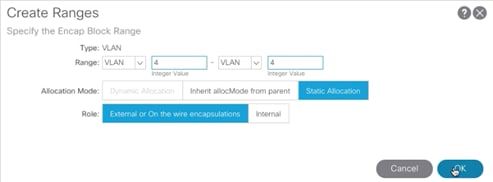
5. Click Submit to finish creating VLAN pool.
Create AEP for Spine connectivity
1. Log into the APIC GUI and follow Fabric->Access Policies.
2. In the left pane, expand Global Policies, right click on Attachable Access Entity Profile and select Create Attachable Access Entity Profile.
3. Provide a Name for the AEP (MultiPod-aep) and click Next.

4. Click Finish to complete the AEP creation without adding any interfaces.
Create External Routed Domain for Spine connectivity
1. Log into the APIC GUI and follow Fabric->Access Policies.
2. In the left pane, expand Physical and External Domains, right click on External Routed Domains and select Create Layer 3 Domain.
3. Provide a Name for the Layer 3 domain (MultiPod-L3).
4. From the Associated Attachable Entity Profile drop down menu, select the recently created AEP (MultiPod-aep).
5. From the VLAN Pool drop down menu, select the recently created VLAN Pool (MultiPod-vlans).
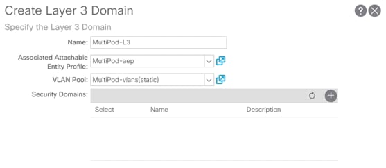
6. Click Submit to finish creating the Layer 3 domain.
Create Link Level Interface Policy for Spine Connectivity
1. Log into the APIC GUI and follow Fabric->Access Policies.
2. In the left pane, expand Interface Policies->Policies->Link Level.
3. Right-click Link Level and select Create Link Level Policy.
4. Provide a name for the Link Level Policy (MultiPod-inherit) and make sure Auto Negotiation is set to on and Speed is set to inherit.
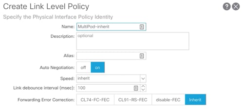
5. Click Submit to create the policy.
Create Spine Policy Group
1. Log into the APIC GUI and follow Fabric->Access Policies.
2. In the left pane, expand Interface Policies->Policy Groups.
3. Right-click Spine Policy Group and select Create Spine Access Port Policy Group.
4. Provide a Name for the Spine Access Port Policy Group (MultiPod-PolGrp).
5. From the Link Level Policy drop-down list, select recently created policy (MultiPod-Inherit).
6. From the CDP Policy drop-down list, select the previously created policy to enable CDP (CDP-Enabled).
7. From the Attached Entity Profile drop down menu, select the recently created AEP (MultiPod-aep).
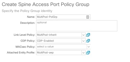
8. Click Submit.
Create Spine Interface Profile
1. Log into the APIC GUI and follow Fabric->Access Policies.
2. In the left pane, expand Interface Policies->Profiles.
3. Right-click Spine Profiles and select Create Spine Interface Profile.
4. Provide a Name for the Spine Interface Profile (MultiPod-Spine-IntProf).
5. Click + to add Interface Selectors.

6. Provide a Name for the Spine Access Port Selector (Spine-Intf).
7. For Interface IDs, add interfaces that connect to the two IPN devices (4/29-4/30).
8. From the Interface Policy Group drop down menu, select the recently created Policy Group (MultiPod-PolGrp).
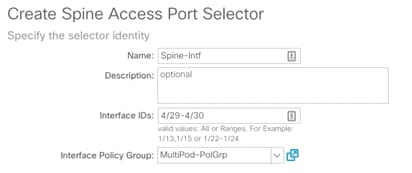
9. Click OK to finish creating Access Port Selector.
10. Click Submit to finish creation Spine Interface Profile.
Create Spine Profile
1. Log into the APIC GUI and follow Fabric->Access Policies.
2. In the left pane, expand Switch Policies->Profiles.
3. Right-click Spine Profiles and select Create Spine Profile.
4. Provide a Name for the Spine Profile (Spine-Prof).
5. Click + to add Spine Selectors.
6. Provide a Name for the Spine Selector (Pod1-Spines) and from the drop-down list under Blocks, select the spine switch IDs (211-212).
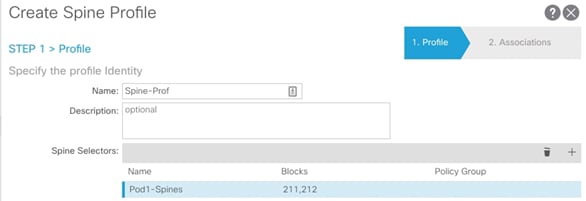
7. Click Update and then click Next.
8. For the Interface Selector Profiles, select the recently created interface selector profile (MultiPod-Spine-intProf).

9. Click Finish to complete creating Spine Profile.
Multi-Pod Setup Configuration
When the original FlashStack with ACI setup was completed, a Pod (1) and the TEP Pool (10.12.0.0/16) was created as part of the setup. In this configuration step, Pod and TEP addresses are defined for the second Site and Multi-Pod is configuration is completed on the APIC. The Pod ID used for second Site is 11 and the TEP Pool used is 10.11.0.0/16.
Setup Pod and TEP Pool for Site 2
1. Log into the APIC GUI and follow Fabric-> Inventory.
2. In the left pane, right click on Pod Fabric Setup Policy and select Setup Pods.
3. Enter the Pod ID and TEP Pool for Site 2.

4. Click Submit.
Create Multi-Pod
1. Log into the APIC GUI and follow Fabric-> Inventory.
2. In the left pane, right-click Pod Fabric Setup Policy and select Create Multi-Pod.
3. Provide a Community string (extended:as2-nn4:5:16).
4. Select Enable Atomic Counters for Multi-pod Mode.
5. Select Peering Type as Full Mesh (since there are only two sites).
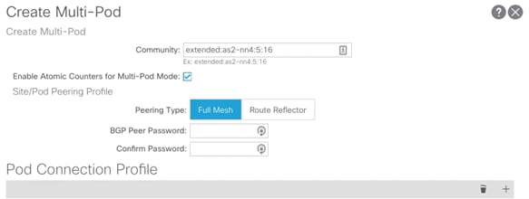
6. Click + to add a Pod Connection Profile.
7. Add Pod 1 and provide Dataplane TEP or ETEP shared by Spines at Site 1 as outlined in TEP Interfaces and click Update.
8. Add Pod 11 and provide Dataplane TEP or ETEP shared by Spines at Site 2 as outlined in TEP Interfaces and click Update.

9. Click + to add Fabric External Routing Profile.
10. Provide a name (FabExtRoutingProf) and define the subnets used for defining point-to-point connections between Spines and IPN devices. In this guide, all the point-to-point connections and within following two subnets: 10.241.0.0/16 and 10.242.0.0/16. Click Update.

11. Click Submit to complete the Multi-Pod configuration.
Create Routed Outside for MultiPod
1. Log into the APIC GUI and follow Fabric-> Inventory.
2. In the left pane, right click on Pod Fabric Setup Policy and select Create Routed Outside for Multipod.
3. Provide the OSPF Area ID as configured on the IPN devices (0.0.0.0).
4. Select the OSPF Area Type (Regular area).
5. Click Next.
6. Click + to add first Spine.
7. Select the first Spine (Pod-1/Node-211) and add Router ID (Loopback) as shown in Figure 39 and click Update.
8. Click + to add second Spine.
9. Select the second Spine (Pod-1/Node-212) and add Router ID (Loopback) and click Update.

10. From the drop-down list for OSPF Profile for Sub-Interfaces, select Create OSPF Interface Policy.
11. Provide a Name for the Policy (P2P).
12. Select Network Type Point-to-Point.
13. Check Advertise Subnet and MTU ignore.

14. Click Submit.
15. Click + to add Routed Sub-Interfaces.
16. Add all four interfaces (Path) and their respective IP addresses connecting the Spines to IPN devices.

17. Click Finish.
18. Browse to Tenants -> Infra.
19. In the left pane, expand the Networking->External Routed Networks and click multipod.
20. From the External Routed Domain drop-down list on the main page, select MultiPod-L3.
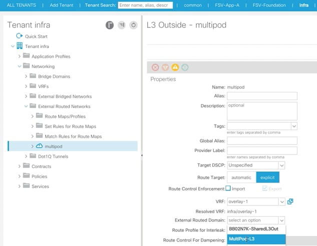
21. Click Submit.
The Site-1 spine configuration is now complete. Log into the IPN devices to verify OSPF routing and neighbor relationship.
Site 2 Spine Discovery
With the Multi-Pod network configured on Site 1, the Spines on the Site 2 should now be visible under the Fabric->Inventory->Fabric Membership.
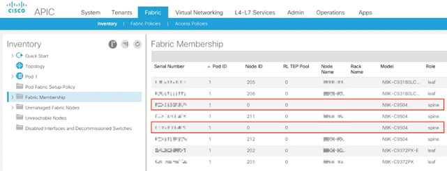
Setup Pod and Node IDs for the Site 2 Spines
1. Log into the APIC GUI and follow Fabric-> Inventory->Fabric Membership
2. In the main window, double-click and update Pod ID (11), Node ID (1111 and 1112) and Node Names for both the new Spines.
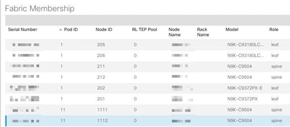
Site 2 Spine Configuration
After adding the Spines to the Fabric, the next step is to configure the Spines on Site 2 to correctly communicate with the IPN devices on Site 2. The leaf switches from Site 2 will not be visible unless this step is complete.
1. Log into the APIC GUI and follow Fabric->Access Policies.
2. From the left pane, expand Switch Policies-> Profiles->Spine Profiles.
3. Select the previously created Spine Profile (Spine-Prof).
4. In the main window, click + to add additional (Site 2) spines.
5. Provide a Name and select the Node IDs for the two spines (1111-1112).

6. Click Update.
Create Routed Outside for Site 2 Spines
1. Log into the APIC GUI and follow Fabric-> Inventory.
2. In the left pane, right click on Pod Fabric Setup Policy and select Create Routed Outside for A Pod.
3. Click + to add first Spine.
4. Select the first Spine (Pod-11/Node-1111) and add Router ID (Loopback) and click Update.
5. Click + to add second Spine.
6. Select the second Spine (Pod-11/Node-1112) and add Router ID (Loopback) and click Update.

7. Click + to add Routed Sub-Interfaces.
8. Add all four interfaces (Path) and their respective IP addresses connecting the Spines to IPN devices.

9. Click Submit.
10. The Site-2 spine configuration is now complete. Log into the IPN devices to verify OSPF routing and neighbor relationship.
Site 2 Leaf Discovery
With the Multi-Pod network configured on Site 2, all the Leaf switches on the Site 2 should now be visible under the Fabric->Inventory->Fabric Membership. In the main window, double-click and update Pod ID (11), Node ID, and Node Names for the leaf devices.
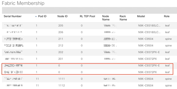
With the discovery and addition of the Site 2 devices, the Multi-Pod portion of the configuration is now complete.
Configuring the Secondary Site to the VMM
A new Virtual Machine Manager (VMM) domain for the vCenter will not be created for the second site, instead the existing VMM domain that associates the ACI fabric to the APIC generated vDS will be associated to the UCS Attachable Access Entity Profile (AEP) that was created for the secondary site UCS connection.
![]() The AEP for the second site Cisco UCS is automatically created during the APIC vPC creation wizard for connecting Cisco UCS Fabric Interconnects to the Nexus leafs they are associated with.
The AEP for the second site Cisco UCS is automatically created during the APIC vPC creation wizard for connecting Cisco UCS Fabric Interconnects to the Nexus leafs they are associated with.
To associate the VMM from within the APIC GUI, complete the following steps:
1. Select the Fabric tab, and select External Access Policies within the Fabric tab.
2. Under External Access Policies on the left hand column, select Policies -> Global -> Attachable Access Entity Profiles -> <Selecting the AEP for the secondary site UCS>.

3. Click the + mark to the far right of the Domains option within Properties.
4. Click Continue past any Policy Usage Warning pop-up that may occur.
5. Select the VMM from the drop-down list that appears within Domains.
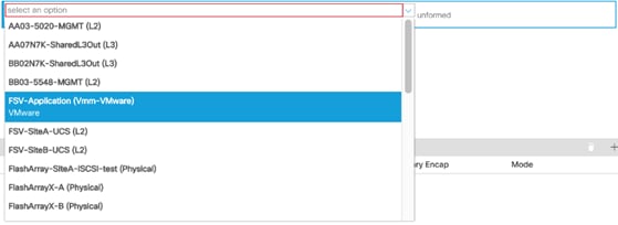
6. Click Update to add the VMM.
Create a Cross-Site Bridge Domain
The cross site FlashStack infrastructure EPGs will share a common Bridge Domain (BD). Optionally, these can be dedicated BD per EPG, but a common BD was used in the validated environment.
To create the cross site BD, complete the following steps from within the APIC GUI:
1. Select the Tenants tab, and select the Tenant FSV-Foundation or otherwise named infrastructure tenant of the FlashStack.
2. Right-click Networking and select the Create Bridge Domain option.
3. Within Step 1 of the dialogue, provide a name for the cross site BD (Foundation-Cross-Site).
4. Select the VRF to be FSV-Foundation.
5. Change Forwarding to Custom.
6. Change L2 Unknown Unicast to Flood.
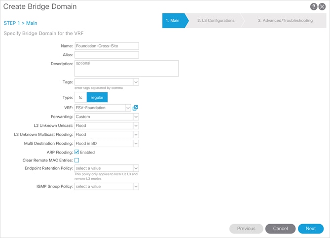
7. Click Next.
8. Leave Step 2 options as defaults, and click Next.
9. Leave Step 3 options as defaults, and click Finish.
Configuring Cross-Site EPGs
As with the VMM configuration in the previous steps, the Application Profiles and EPGs that will be used across both sites have mainly been created, with the exception of an Application Profile and EPG for Replication traffic between the two FlashArrays used for ActiveCluster. The following EPGs will be created, or have previously been created during the single site setup, within the FSV-Foundation tenant:
· vMotion
· iSCSI-A
· iSCSI-B
· IB-Mgmt (site specific or cross site)
To configure the EPGs from within the APIC GUI, complete the following steps (vMotion EPG example shown below):
1. Select the Tenants tab, and select the Tenant FSV-Foundation or otherwise named infrastructure tenant of the FlashStack.
2. Within Application Profiles, select the AP the vMotion EPG was created, Host-Connectivity is the example from the previous deployment guide.
3. Right-click the vMotion EPG and select the Deploy Static EPG on PC, VPC, or Interface.
4. Select the following options:
a. Path Type: Virtual Port Channel
b. Path: <Leaf Switch connection for site being added for the UCS-A Policy Group>
c. Port Encap: <leave as VLAN>, set Integer Value to vMotion VLAN
d. Deployment Immediacy: Immediate
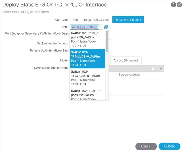
e. Click Submit.
5. Repeat steps 1-4 to add the UCS-B Policy Group to the vMotion EPG.
6. Select Policy within the vMotion EPG, and select General within the Policy options.
7. Set the Bridge Domain the Foundation-Cross-Site BD that was previously created.
8. Click Submit.
9. Repeat steps 1-9 for both iSCSI EPGs, as well as the appropriate IB-Mgmt EPG that may be extended across sites.
ActiveCluster Replication EPG
The ActiveCluster Replication connections will need their own cross site EPG in place, but will need to additionally consume contracts to reach whatever site specific or cross site management EPG(s) that the FlashArray management interfaces are connected to.
To configure the Application Profile and EPG from within the APIC GUI, complete the following steps:
1. Select the Tenants tab, and select the Tenant FSV-Foundation or otherwise named infrastructure tenant of the FlashStack.
2. Right-click Application Profiles and select the Create Application Profile option.
3. Provide the name ActiveCluster and click Submit.
4. Right-click the ActiveCluster AP and select the Create Application EPG option.
5. Provide the name Replication to the EPG.
6. Set Flood on Encapsulation to Enabled.
7. Set the Bridge Domain to Foundation-Cross-Site.
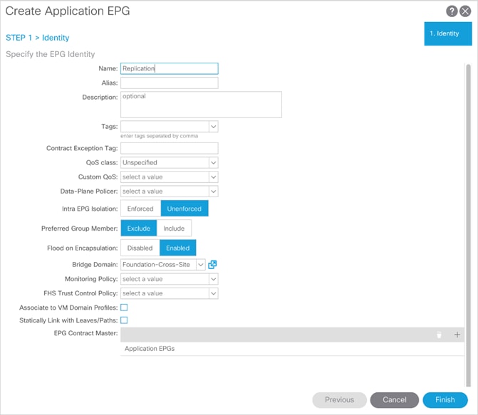
8. Click Finish.
9. Right-click the Replication EPG and select the Deploy Static EPG on PC, VPC, or Interface option.
10. Select the following options:
a. Path Type: Port
b. Path: <Leaf Switch connection for first Replication port from a FlashArray>
c. Port Encap: <leave as VLAN>, set Integer Value to Replication VLAN
d. Deployment Immediacy: Immediate
e. Mode: Access (802.1P)
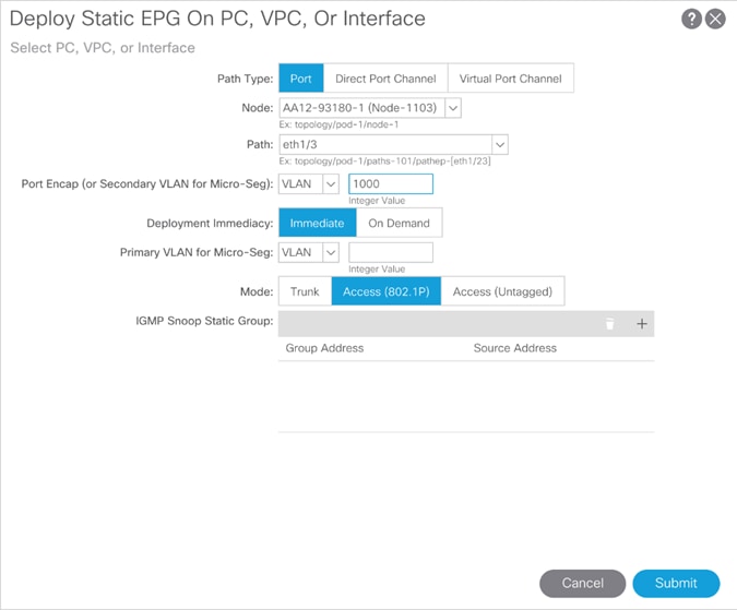
11. Click Submit.
12. Repeat steps 9-11 for the remaining 7 Replication ports across the two FlashArrays.
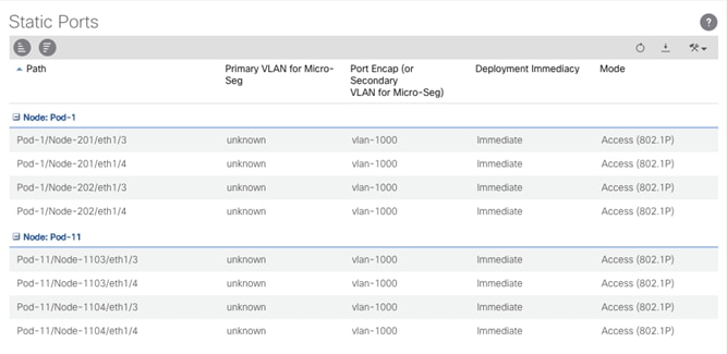
13. Right-click the Replication EPG and select the Add Consumed Contract option.
14. Select the Contract to allow the CrossSite or site-specific management for the first site containing the management interfaces of the FlashArrays.
15. Click Submit.
16. Repeat steps 14 and 15 for the second site if necessary.
Pure Storage ActiveCluster Configuration
A major benefit of using an ActiveCluster stretched storage solution is how simple it is to setup.
ActiveCluster Glossary of Terms
The following terms will be used repeatedly in this document that have been introduced for ActiveCluster:
· Pod—a pod is a namespace and a consistency group. Synchronous replication can be activated on a pod, which makes all volumes in that pod present on both FlashArrays in the pod.
· Stretching—stretching a pod is the act of adding a second FlashArray to a pod. When stretched to another array, the volume data will begin to synchronize, and when complete all volumes in the pod will be available on both FlashArrays
· Unstretching—unstretching a pod is the act of removing a FlashArray from a pod. This can be done from either FlashArray. When removed, the volumes and the pod itself, are no longer available on the FlashArray that was removed.
· Restretching— when a pod is unstretched, the other array (the array unstretched from) will keep a copy of the pod in the trash can for 24 hours, and this would allow the pod to be quickly re-stretched without having to resend all the data if restretched prior to 24 hours.
Creating a Synchronous Connection
The first step to enable ActiveCluster is to create a synchronous connection with another FlashArray. It does not matter which FlashArray that is used to create the connection, either one is fine.
To create a synchronous connection, complete the following steps:
1. Log into the FlashArray Web Interface and click on the Storage section. Click either the plus sign or the vertical ellipsis and choose Connect Array.
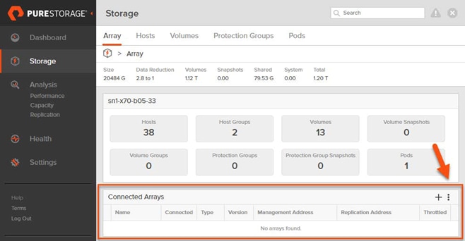
The window that pops-up requires three pieces of information:
· Management address—this is the virtual IP address or FQDN of the remote FlashArray.
· Connection type—choose Sync Replication for ActiveCluster.
· Connection Key—this is an API token that can be retrieved from the remote FlashArray.
2. To obtain the connection key, login to the remote FlashArray Web Interface and click the Storage section and then click the vertical ellipsis and choose Get Connection Key.

3. Copy the key to the clipboard using the Copy button.
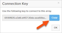
4. Go back to the original FlashArray Web Interface and paste in the key.
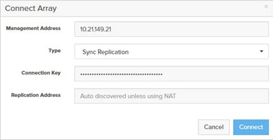
![]() The replication address field may be left blank and Purity will automatically discover all the replication port addresses. If the target addresses are via Network Address Translation (NAT) then it is necessary to enter the replication port NAT addresses.
The replication address field may be left blank and Purity will automatically discover all the replication port addresses. If the target addresses are via Network Address Translation (NAT) then it is necessary to enter the replication port NAT addresses.
5. When complete, click Connect.
If everything is valid, the connection will appear in the Connected Arrays panel.

If the connection fails, verify network connectivity and IP information and/or contact Pure Storage Support.
Creating a Pod
The next step to enable ActiveCluster is to create a consistency group. With ActiveCluster, this is a called a “pod”.
A pod is both a consistency group and a namespace—in effect creating a grouping for related objects involved in ActiveCluster replication. One or more pods can be created. Pods are stretched, unstretched, and failed over together.
Therefore, the basic idea for one or more pods is simply to put related volumes in the same pod. If they host related applications that should remain in the same datacenter together or have consistency with one another, put them in the same pod. Otherwise, put them in the same pod for simplicity, or different ones if they have different requirements.
See the following KB for FlashArray object limits for additional guidance:
To create a pod, complete the following steps:
1. Log into the FlashArray GUI and click Storage, then Pods, then click the plus sign.
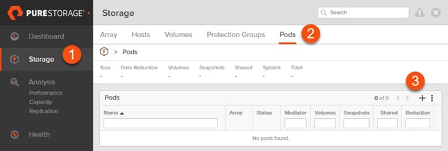
2. Enter a name for the pod, this can be letters, numbers or dashes (must start with a letter or number). Click Create.

The pod will then appear in the Pods panel.

3. To continue to configure the pod, click the pod name.
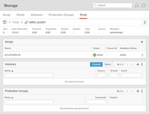
The default configuration for ActiveCluster is to use the Cloud Mediator—no configuration is required other than ensure the management network from the FlashArray is redundant (uses two NICs per controller) and have IP access to the mediator. Refer to the networking section in for more information:
The mediator in use can be seen in the overview panel under the Mediator heading. If the mediator is listed as “purestorage” the Cloud Mediator is in use.

For sites that are unable to contact the Cloud Mediator, the ActiveCluster On-Premises Mediator is available.
For deployment instructions, refer to the following article:
Pod configuration is complete.
Adding Volumes to a Pod
The next step is to add any pre-existing volumes to the pod. Once a pod has been enabled for replication, pre-existing volumes cannot be moved into the pod, only new volumes can be created in the pod.
To add a volume to a pod, complete the following steps:
1. Go to the Storage screen in the FlashArray Web Interface and click Volumes.
2. Click the name of a volume to be added to the pod. To find the volume quickly, search for its name.
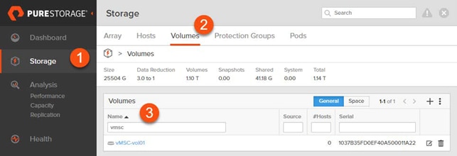
3. When the volume screen loads, click the vertical ellipsis in the upper right-hand corner and choose Move.
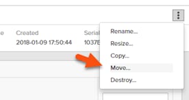
4. To select the pod, click the Container box and choose the pod name.
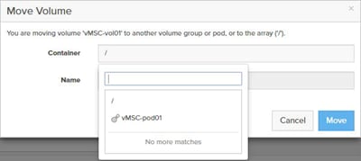
![]() As of Purity 5.0.0, the following limitations exist with moving a volume into or out of a pod: Volumes cannot be moved directly between pods; a volume must first be moved out of a pod, then moved into the other pod; a volume in a volume group cannot be added into a pod. It must be removed from the volume group first; a volume cannot be moved out of an already stretched pod. The pod must first be unstretched, then the volume can be moved out; a volume cannot be moved into an already stretched pod. It must first be unstretched and then an existing volume into it can be added. At this point the pod can then be restretched.
As of Purity 5.0.0, the following limitations exist with moving a volume into or out of a pod: Volumes cannot be moved directly between pods; a volume must first be moved out of a pod, then moved into the other pod; a volume in a volume group cannot be added into a pod. It must be removed from the volume group first; a volume cannot be moved out of an already stretched pod. The pod must first be unstretched, then the volume can be moved out; a volume cannot be moved into an already stretched pod. It must first be unstretched and then an existing volume into it can be added. At this point the pod can then be restretched.
Some of these restrictions may be removed in future Purity versions.
5. Choose the valid target pod and click Move.
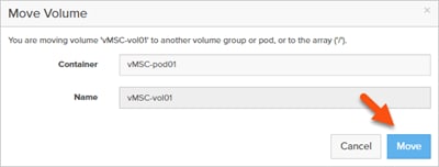
This will move the volume into the pod and rename the volume to have prefix consisting of the pod name and two colons. The volume name will then be in the format of <podname>::<volumename>.
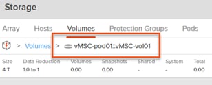
The pod will list the volume under its Volumes panel.
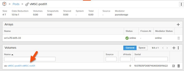
Creating a New Volume in a Pod
To create new volumes directly in a pod, complete the following steps:
1. Click Storage > Pods, then choose the pod. Under the Volumes panel, click the plus sign to create a new volume.

2. In the creation window, enter a valid name and a size and click Create. This can be done whether or not the pod is actively replicating.
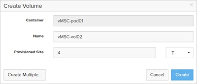
Stretching a Pod
| The next step is adding a FlashArray target to the pod. This is called “stretching” the pod, because it automatically makes the pod and its content available on the second array.
|
To stretch a pod, complete the following steps:
1. Add a second array to the pod. Click the plus sign in the Arrays panel.

2. Choose a target FlashArray and click Add.

The arrays will immediately start synchronizing data between the two FlashArrays.

Active/Active storage is not available until the synchronization completes which will be shown when the resyncing status ends and both arrays are online.

On the remote FlashArray the pod and volumes now exist in identical fashion and will be available for provisioning to a host or hosts on either FlashArray.
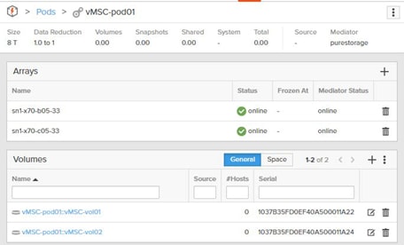
Un-Stretching a Pod
When ActiveCluster has been enabled, replication can also be terminated by unstretching it. This might be done for a variety of reasons, such as to change the pod volume membership, or maybe the replication was temporarily enabled to migrate the volumes from one array to another.
The act of terminating replication is called un-stretching. To un-stretch a pod, remove the array which no longer needs to host the volumes, see the example below:

In this example, the pod has two arrays; sn1-x70-b05-33 and sn1-x70-c05-33. Since this pod is online, both arrays offer up the volumes in the pod. If you want the volumes to only remain on sn1-x70-b05-33, then remove the other FlashArray, sn1-x70-b05-33.
![]() Before removing a FlashArray from a pod, make sure that the volumes in the pod are disconnected from any host or host group on the FlashArray to be removed from the pod. Purity will not allow a pod to be unstretched if the FlashArray chosen for removal has existing host connections to volumes in the pod.
Before removing a FlashArray from a pod, make sure that the volumes in the pod are disconnected from any host or host group on the FlashArray to be removed from the pod. Purity will not allow a pod to be unstretched if the FlashArray chosen for removal has existing host connections to volumes in the pod.
To remove a FlashArray, complete the following steps:
1. Select the appropriate pod and from of the Arrays panel, click the trash icon next to the array to be removed

2. When it has been confirmed that it is the proper array to remove, click the Remove button to confirm the removal.

3. On the FlashArray that was removed, under the Pods tab, the pod will be listed in the Destroyed Pods panel.

![]() If the un-stretch was done in error, go back to the FlashArray Web Interface that remains in the pod and add the other FlashArray back. This will remove the pod from the Destroyed Pods status back to active.
If the un-stretch was done in error, go back to the FlashArray Web Interface that remains in the pod and add the other FlashArray back. This will remove the pod from the Destroyed Pods status back to active.
4. The pod can be instant re-stretched for 24 hours. At 24 hours, the removed FlashArray will permanently remove its references to the pod. Permanent removal can be forced early by selecting the destroyed pod and clicking the trash icon next to it.

5. Click Eradicate to confirm the removal.

When the pods are created, the ESXi host connections can be added as described earlier in this document.
Host Connectivity
The FlashArray supports connections through iSCSI and Fibre Channel and both are supported with ActiveCluster. Prior to being able to provision storage, a “host” object must be created on the FlashArray respectively for each ESXi server. Hosts can then be further organized into Host Groups. Host groups collect host objects together so that volumes can be provisioned to them all at once; host groups are recommended for clustered hosts, such as ESXi, so that storage can be provisioned uniformly to all hosts.
Hosts
A FlashArray host object is a collection of a host’s initiators that can be “connected” to a volume. This allows those specified initiators (and therefore that host) to access that volume or volumes.
To create a host object, complete the following steps:
1. Go to the Storage section and then the Hosts tab.
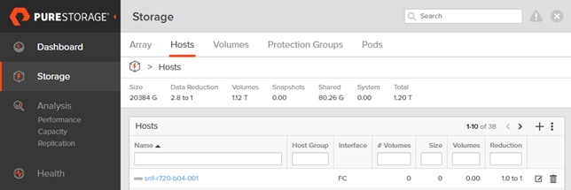
2. Click the plus sign in the Hosts panel to create a new host. Assign the host a name that makes sense and click Create.

3. Click the newly created host and then in the Host Ports panel, click the vertical ellipsis and choose either Configure WWNs (for Fibre Channel) or Configure IQNs (for iSCSI).

4. For WWNs, if the initiator is presented on the fabric to the FlashArray (meaning zoning is complete), click in the correct WWN in the left pane to add it to the host, or alternatively click the plus sign and type it in manually. iSCSI IQNs must be typed in manually always.
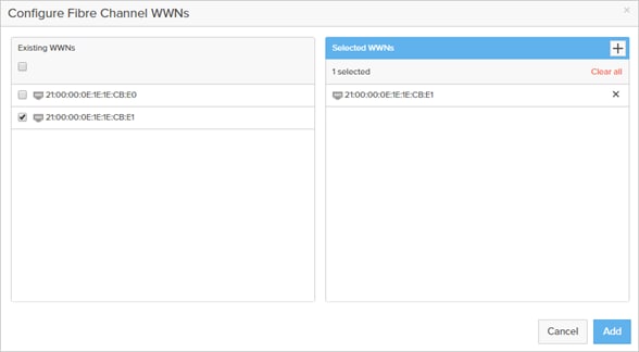
5. When all the initiators are added/selected, click Add.
6. Verify connectivity by navigating to the Health section and then the Connections tab. Find the newly created host and look at the Paths column. If it lists anything besides Redundant, investigate the reported status.

Host Groups
To make it easier to provision storage to a cluster of hosts, it is recommended to put all the FlashArray host objects into a host group.
To create a host group, complete the following steps:
1. Click the Storage section followed by the Hosts tab. In the Host Group panel, click the plus sign.

2. Enter a name for the host group and click Create.

3. Click the host group in the Host Groups panel and then click the vertical ellipsis in the Member Hosts panel and select Add.

4. Select one or more hosts shown in the following screenshot to add to the host group.
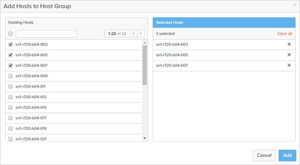
![]() If the environment is configured for uniform access, all hosts in the ESXi cluster should be configured on both FlashArrays and added to their host group. If the configuration is non-uniform, only the hosts that have direct access to the given FlashArray need to be added to that FlashArray and its corresponding host group.
If the environment is configured for uniform access, all hosts in the ESXi cluster should be configured on both FlashArrays and added to their host group. If the configuration is non-uniform, only the hosts that have direct access to the given FlashArray need to be added to that FlashArray and its corresponding host group.
Multipathing
Standard ESXi multipathing recommendations apply that are described in more detail in the VMware Best Practices guide found here: https://support.purestorage.com/@api/deki/files/5449/FlashArray_VMware_vSphere_Best_Practices.pdf.
The high-level recommendations include the following:
· Use the VMware Round Robin path selection policy for FlashArray storage with the I/O Operations Limit set to 1.
· In ESXi 6.0 Express Patch 5 and ESXi 6.5 Update 1 and later this is a default setting in ESXi for FlashArray storage and therefore no manual configuration is required in those releases.
· Use multiple HBAs per host for Fibre Channel or multiple NICs per host for iSCSI.
· It is recommended to use Port Binding for Software iSCSI when possible.
· Connect each host to both controllers.
· In the storage or network fabric, use redundant switches
Uniform Storage Configuration
In a uniform configuration, all hosts have access to both FlashArrays and can therefore see paths for a ActiveCluster-enabled volume to each FlashArray.
To create a new VMFS volume on one of the FlashArrays, complete the following steps:
![]() To expedite the process, it is advisable to use the vSphere Web Client plugin, but for the purposes of explanation, we will use the FlashArray Web Interface and the vSphere Web Client.
To expedite the process, it is advisable to use the vSphere Web Client plugin, but for the purposes of explanation, we will use the FlashArray Web Interface and the vSphere Web Client.
In this example, there is an eight-node ESXi cluster; each host is zoned to both FlashArrays.
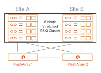
Hosts for this cluster are shown in the vCenter view below.
Figure 40 The vCenter Cluster
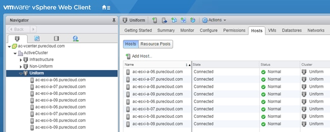
Each of these hosts are added into a Host Group on the FlashArray to allow uniform connectivity as shown in Figure 41.
Figure 41 Corresponding Host Group on the First FlashArray
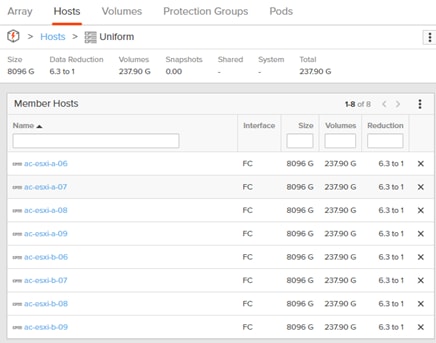
1. For the second FlashArray, create a volume on my FlashArray in site A and add it to pod “vMSC-pod01.”
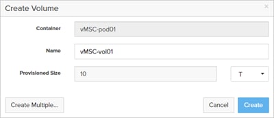
The pod is not stretched to the FlashArray in site B.
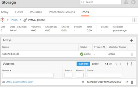
2. Add it to my host group on the FlashArray in site A.
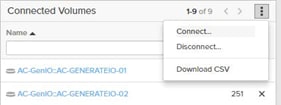
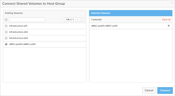
My volume is now in the host group “Uniform” and is in an un-stretched pod on the FlashArray in site A.
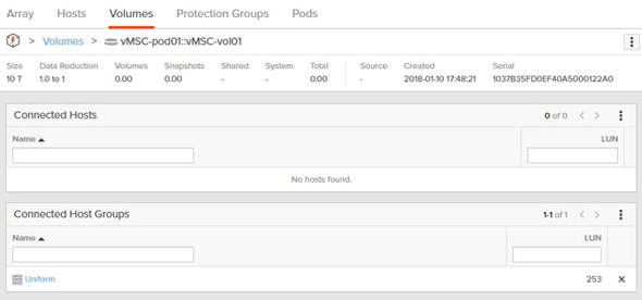
The next step is to rescan the vCenter cluster.
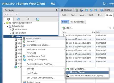
3. When the rescan is complete, click one of the ESXi hosts and then go to the Configure tab, then Storage Devices and select the new volume that was provisioned and look at the Paths tab.
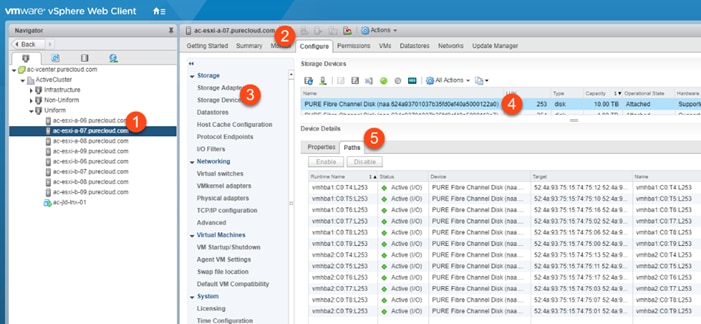
There are now 12 paths to the new volume on the FlashArray in site A. All of them are active for I/O.
4. Stretch the pod to the FlashArray in site B.

As soon as the FlashArray is added, the pod will start synchronizing and when it is complete the pod will go fully online and the volume will be available on both FlashArrays

5. For the hosts to see it on the second FlashArray, add the volume to the proper host or host group on that FlashArray.
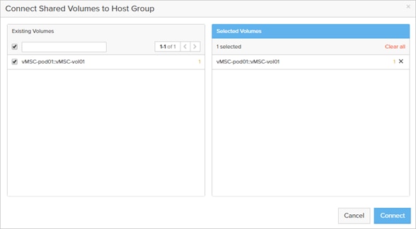
6. To view the additional paths, rescan the ESXi cluster.

When the rescan is done, the new paths to the volume via the second FlashArray will appear.
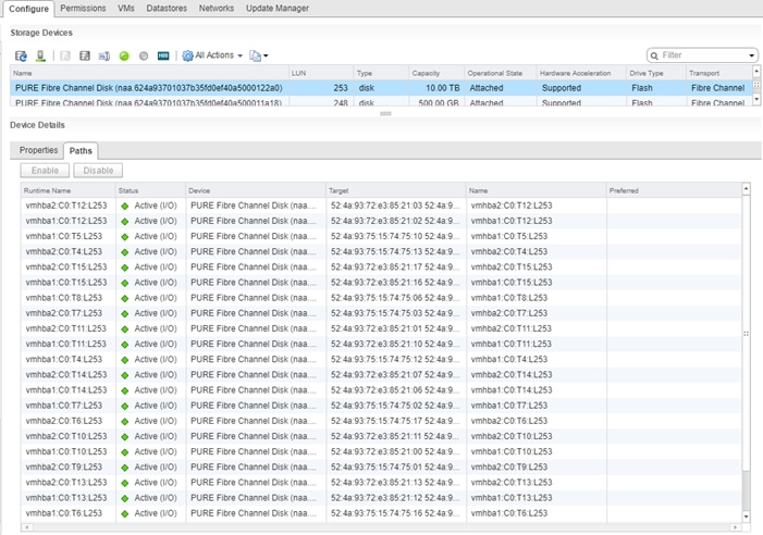
Preferred Paths
The default behavior is that all paths from a FlashArray to a host will be actively used by ESXi, even ones from the secondary FlashArray. When replication occurs over extended distances, this is generally not ideal. In situations where the sites are far apart, two performance-impacting things occur:
· Half of the writes (assuming both FlashArrays offer an equal amount of paths for each device) sent from a host in site A will be sent to the FlashArray in site B. Since writes must be acknowledged in both sites, this means the data traverses the WAN twice. First the host issues a write across the WAN to the far FlashArray, and then the far FlashArray forwards it back across the WAN to the other FlashArray. This adds unnecessary latency. The optimal path is for the host to send writes to the local FlashArray and then the FlashArray forwards it to the remote FlashArray. In the optimal situation, the write must only traverse the WAN once.
· Half of the reads (assuming both FlashArrays offer an equal amount of paths for each device) sent from a host in site A will be sent to the FlashArray in site B. Reads can be serviced by either side, and for reads there is no need for one FlashArray to talk to the other. As a result, reads will not traverse the WAN in normal circumstances. Servicing all reads from the local array to a given host is the best option for performance.
The FlashArray offers an option to intelligently tell ESXi which FlashArray should optimally service I/O in the event a ESXi host can see paths to both FlashArrays for a given device. This is a FlashArray host object setting called Preferred Arrays.
In a situation where the FlashArray are in geographically different datacenters it is important to set the preferred array for a host on BOTH FlashArrays.
1. For each host, login to the FlashArray Web Interface for the array that is local to that host. Click the Storage section, then the Hosts tab, then choose the host to be configured. In the Details panel, click the Add Preferred Arrays option.
![]() BEST PRACTICE: For every host that has access to both FlashArrays that host an ActiveCluster volume, set the preferred FlashArray for that host on both FlashArrays. Tell FlashArray A that it is preferred for host A. Tell FlashArray B that FlashArray A is preferred for host A. Doing this on both FlashArrays allows a host to automatically know which paths are optimized and which are not.
BEST PRACTICE: For every host that has access to both FlashArrays that host an ActiveCluster volume, set the preferred FlashArray for that host on both FlashArrays. Tell FlashArray A that it is preferred for host A. Tell FlashArray B that FlashArray A is preferred for host A. Doing this on both FlashArrays allows a host to automatically know which paths are optimized and which are not.
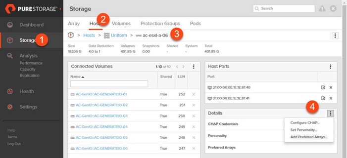
2. Select the FlashArray as preferred for the ESXi host and click Add.
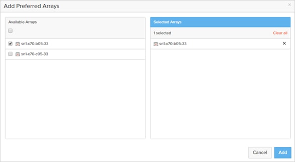
3. If that same host exists on the remote FlashArray, login to the remote FlashArray Web Interface. Click the Storage section, then the Hosts tab, then choose the host to be configured. In the Details panel, click the Add Preferred Arrays option.
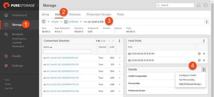
4. Select the previous FlashArray as preferred for that ESXi host and click Add.
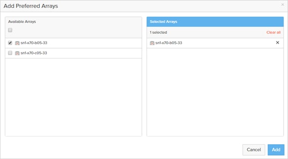
It can then be seen in vSphere that half of the paths are marked as Active and the others are marked as Active (I/O). The Active (I/O) paths are the paths that are used for VM I/O. The other paths will only be used if the paths to the preferred FlashArray are not available.
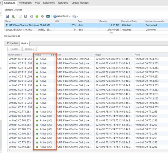
![]() When a preferred array has been turned off/on or changed, the FlashArray issues 6h/2a/6h (Sense code/ASC/ASCQ) which translates to UNIT ATTENTION ASYMMETRIC ACCESS STATE CHANGED to the host to inform it of the path state change proactively.
When a preferred array has been turned off/on or changed, the FlashArray issues 6h/2a/6h (Sense code/ASC/ASCQ) which translates to UNIT ATTENTION ASYMMETRIC ACCESS STATE CHANGED to the host to inform it of the path state change proactively.
Virtualization
The FlashStack will deploy a vSphere cluster using vSphere 6.5 U1 that will span both sites.
Instructions for vSphere ESXi setup as well as vCenter deployment can be found in the previously released FlashStack Virtual Server Infrastructure with Cisco Application Centric Infrastructure and Pure Storage FlashArray Design and Implementation Guide: https://www.cisco.com/c/en/us/td/docs/unified_computing/ucs/UCS_CVDs/ucs_flashstack_vsi_vm65_M5_ACI.html
Adjustments to these instructions are required, depending on your implementation:
· Creating a port group in the vSwitch or vDS for either a CrossSite-Mgmt or opposing IB-Mgmt network (IB-Mgmt-A/IB-Mgmt-B) that has been extended and uplinked within the UCS vNIC-Mgmt-A and vNIC-Mgmt-B.
· Creating a VM Affinity rule as shown in Figure 42, for a vCenter hosted within the FlashStack to prefer to run on a set of hosts specific to one site if the vCenter is sitting on an L2 externally extended network of that site.
Figure 42 VM Affinity Rule for Preferred Hosts
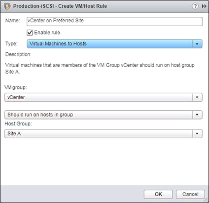
Beyond these two steps, the deployment and configuration should occur as if the vSphere environment is within a single site.
A high-level summary of the FlashStack validation is provided in this section. The solution was validated for basic data forwarding by deploying virtual machine running IOMeter tool. The system was validated for resiliency by failing various aspects of the system under load. Examples of the types of tests executed include:
· Failure and recovery of iSCSI booted ESXi hosts in a cluster
· Storage vMotion between sites
· vSphere HA events between sites utilizing the ActiveCluster stretched pod
· Service Profile migration between blades
· Failure of partial and complete IOM links
· Failure and recovery of redundant links to FlashArray controllers
· Storage link failure between one of the FlashArray controllers and the fabric interconnect
· Load was generated using IOMeter tool and different IO profiles were used to reflect the different profiles that are seen in customer networks
Validated Hardware and Software
Table 2 lists the hardware and software versions used during the solution validation. The versions used have been certified within interoperability matrixes supported by Cisco, Pure Storage, and VMware. For current supported version information, consult the following sources:
· Cisco UCS Hardware and Software Interoperability Tool: https://ucshcltool.cloudapps.cisco.com/public/
· Cisco ACI Compatibility Guide: https://www.cisco.com/c/dam/en/us/solutions/collateral/data-center-virtualization/application-centric-infrastructure/guide-c07-736255.pdf
· Cisco ACI Virtualization Compatibility: https://www.cisco.com/c/dam/en/us/td/docs/Website/datacenter/aci/virtualization/matrix/virtmatrix.html
· Pure Storage Interoperability(note, this interoperability list will require a support login form Pure): https://support.purestorage.com/FlashArray/Getting_Started/Compatibility_Matrix
· VMware Compatibility Guide: https://www.vmware.com/resources/compatibility/search.php
![]() If the versions you select differ from the validated versions below, it is highly recommended to read the release notes of the selected version to be aware of any changes to features or commands that may have occurred.
If the versions you select differ from the validated versions below, it is highly recommended to read the release notes of the selected version to be aware of any changes to features or commands that may have occurred.
Table 2 Hardware and Software Versions
| Layer |
Device |
Image |
| Compute |
Cisco UCS 6332-16UP Fabric Interconnect |
3.2(3d) |
|
|
Cisco UCS B-200 M5 |
3.2(3d) |
|
|
|
|
| Network |
Cisco Nexus 93180YC-EX ACI (Site A Leafs) |
3.2(1l) |
|
|
Cisco Nexus 93180LC-EX ACI (Site B Leafs) |
3.2(1l) |
|
|
Cisco Nexus 9504 (Site A & B Spines) |
3.2(1l) |
| Storage |
Pure Storage FlashArray //X70 |
5.0.6 |
| Software |
Cisco UCS Manager |
3.2(3d) |
|
|
VMware vSphere ESXi |
6.5 U1 |
|
|
Cisco ESXi eNIC |
1.0.16.0 |
|
|
VMware vCenter |
6.5 U1 |
|
|
Pure Storage vSphere Web Client Plugin |
3.0.0 |
FlashStack delivers a platform for Enterprise and cloud datacenters using Cisco UCS Blade Servers, Cisco Fabric Interconnects, Cisco Nexus 9000 switches, and fibre channel or iSCSI attached Pure Storage FlashArray//X. The incorporation of Cisco ACI Multi-Pod and Pure Storage ActiveCluster allows this platform to potentially exist across multiple data centers, with both seamless network connectivity and synchronous data across these datacenters. FlashStack with ACI Multi-Pod and Pure Storage ActiveCluster is designed and validated using compute, network and storage best practices for high performance, high availability, and simplicity in implementation and management.
This Cisco Validated Design confirms the design, performance, management, scalability, and resilience that FlashStack provides to customers across extended data centers.
Bare-Metal Migration with FlashStack Multi-Pod and Cisco UCS Central
This section covers a bare metal deployment of RHEL that was iSCSI booted from an iSCSI LUN replicated between the two sites by a stretched pod within ActiveCluster. The UCS Service Profile for the bare metal host was imported into Cisco UCS Central, and made available to both UCS domains at the respective sites.
Cisco UCS has native portability of UCS Service Profiles within a UCS domain. With Cisco UCS Central, that portability can extend between UCS domains, making an environment like FlashStack with Multi-Pod an ideal candidate for considering the migration between sites of a service profile hosting a bare metal server. This bare metal server will need to use VLANs (iSCSI and compute data) that are extended to both sites of the ACI Inter Pod Network, and utilize a volume that is part of an ActiveCluster stretched pod between FlashArrays.
When Cisco UCS Central is registered to a UCS domain, Cisco UCS Central has wizards to globalize VLANs and VSANs within the UCS domain, as well as Service Profiles local to a UCS domain. The VLANs and VSANs used by a global UCS Service Profile need to be managed by Cisco UCS Central, as well as pools and policies associated to a globalized UCS Service Profile.
Service Profiles and Service Profile Templates can be created directly in Cisco UCS Central from the top of the Cisco UCS Central Interface, in an input box presented as "What do you want to do?"

Entering key words can display relevant operations.

The globalization task wizards are available from this same drop-down list.

![]() Alternately, a full list of wizards and tasks can be found by expanding the drop-down list.
Alternately, a full list of wizards and tasks can be found by expanding the drop-down list.
Using the Globalize Local Service Profile wizard, the interface guides you through the dependencies that need to be resolved. In the example of an iSCSI booted host, the following resources are needed to reconcile:
Pools:
· MAC Pool A
· MAC Pool B
· iSCSI IPv4 Pool A
· iSCSI IPv4 Pool B
· IQN Pool
· UUID Pool
Policies:
· Network Control Policy
· Bios Policy
· Local Disk Configuration Policy
· Maintenance Policy
· Boot Policy
· Power Policy
· Power Sync Policy
· Threshold Policy
· Scrub Policy
· Graphics Card Policy
· Host Firmware Package Policy
· vMedia Policy
· Ethernet Adapter Policy
· iSCSI Adapter Policy
· vNIC Templates
· LAN Connectivity Policy
These Pools and Policies will need to be reallocated to global equivalents, or point to the default global-default for a policy. Any bound Service Profile Template would need to be unbound, or have an equivalent global service profile template created to have the global service profile bound to it. OS installation can occur prior to globalization, as long the host's identifying specifications are properly preserved in the conversion of pools and policies associated to the host service profile.
The iSCSI targets need to be adjusted in the Service Profile to specify the boot targets other than the original site in which it may have been configured.
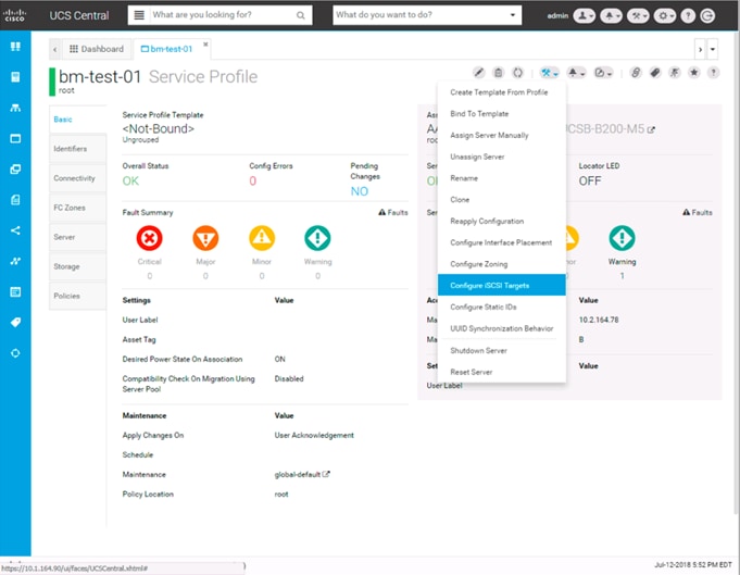
For booting from FlashArrays at either site, the targets have been set for one each between primary and secondary targets:
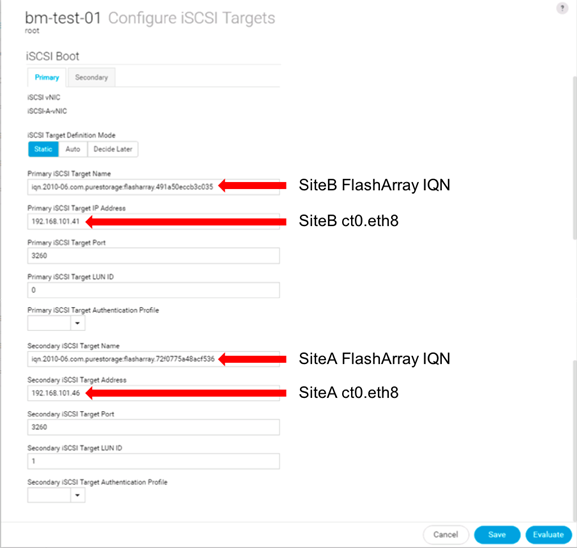
In a permanent migration scenario, the iSCSI target order should be set to list the intended site first within the port order.
After globalization the service profile can be brought up within Cisco UCS Central and selected for association:
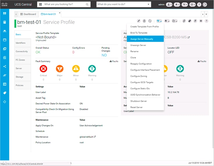
The server can be selected from a general list of resources between available UCS domains, or filtered based on specific criteria:
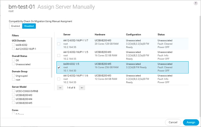
KVM can be launched directly from Cisco UCS Central, or from Cisco UCS Manager from the domain it is being associated:

On boot-up, the server shows connectivity to both FlashArrays for its boot LUN:
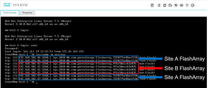
In this state, the UCS Service Profile will continue running the host if either FlashArray is unavailable. If the host was brought down because the site hosting it was unavailable, the host could be brought back up on the remaining site, if Cisco UCS Central was available to make the association.
For more information about the installation and use of Cisco UCS Central, see:
Products and Solutions
Pure Storage FlashArray//X:
https://www.purestorage.com/uk/products/flasharray-x.html
Pure Storage ActiveCluster:
https://www.purestorage.com/products/purity/activecluster.html
Cisco Application Centric Infrastructure:
Cisco Application Centric Infrastructure Multi-Pod:
Cisco Unified Computing System:
http://www.cisco.com/c/en/us/products/servers-unified-computing/index.html
Cisco UCS 6300 Series Fabric Interconnects:
Cisco UCS 5100 Series Blade Server Chassis:
Cisco UCS B-Series Blade Servers:
Cisco UCS Adapters:
Cisco UCS Manager:
http://www.cisco.com/c/en/us/products/servers-unified-computing/ucs-manager/index.html
Cisco Nexus 9000 Series Switches:
http://www.cisco.com/c/en/us/products/switches/nexus-9000-series-switches/index.html
VMware vCenter Server:
http://www.vmware.com/products/vcenter-server/overview.html
VMware vSphere:
https://www.vmware.com/products/vsphere
Ramesh Isaac, Technical Marketing Engineer, Cisco Systems, Inc.
Ramesh Isaac is a Technical Marketing Engineer in the Cisco UCS Data Center Solutions Group. Ramesh has worked in data center and mixed-use lab settings since 1995. He started in information technology supporting Unix environments and focused on designing and implementing multi-tenant virtualization solutions in Cisco labs before entering Technical Marketing. Ramesh holds certifications from Cisco, VMware, and Red Hat.
Don Kirouac, Technical Marketing Engineer, Pure Storage, Inc.
Don is a member of Pure’s Technical Marketing team, responsible for FlashArray replication features, including ActiveCluster as well as FlashArray Performance. He has over 20 years of experience supporting storage network switches, systems, and storage technologies through various roles in solution delivery, architecture, pre-sales and technical marketing. Don studied Computer Mathematics and Economics at Keene State College and Clark University.
Acknowledgements
· Haseeb Niazi, Technical Marketing Engineer, Cisco Systems, Inc.
· Craig Waters, Senior Product Manager, Pure Storage, Inc.

 Feedback