Cisco HyperFlex All-NVMe Systems for Deploying Microsoft SQL Server 2019 Databases with VMware ESXi
Available Languages
Bias-Free Language
The documentation set for this product strives to use bias-free language. For the purposes of this documentation set, bias-free is defined as language that does not imply discrimination based on age, disability, gender, racial identity, ethnic identity, sexual orientation, socioeconomic status, and intersectionality. Exceptions may be present in the documentation due to language that is hardcoded in the user interfaces of the product software, language used based on RFP documentation, or language that is used by a referenced third-party product. Learn more about how Cisco is using Inclusive Language.
- US/Canada 800-553-2447
- Worldwide Support Phone Numbers
- All Tools
 Feedback
 Feedback

Cisco HyperFlex All-NVMe Systems for Deploying Microsoft SQL Server 2019 Databases with VMware ESXi
Deployment Guide for Microsoft SQL Server 2019 Standalone and Failover Cluster Instances (FCI) on Cisco HyperFlex All-NVMe Systems with VMware ESXi 6.7 Update 3
Published: April 2021

About the Cisco Validated Design Program
The Cisco Validated Design (CVD) program consists of systems and solutions designed, tested, and documented to facilitate faster, more reliable, and more predictable customer deployments. For more information, go to:
http://www.cisco.com/go/designzone.
ALL DESIGNS, SPECIFICATIONS, STATEMENTS, INFORMATION, AND RECOMMENDATIONS (COLLECTIVELY, "DESIGNS") IN THIS MANUAL ARE PRESENTED "AS IS," WITH ALL FAULTS. CISCO AND ITS SUPPLIERS DISCLAIM ALL WARRANTIES, INCLUDING, WITHOUT LIMITATION, THE WARRANTY OF MERCHANTABILITY, FITNESS FOR A PARTICULAR PURPOSE AND NONINFRINGEMENT OR ARISING FROM A COURSE OF DEALING, USAGE, OR TRADE PRACTICE. IN NO EVENT SHALL CISCO OR ITS SUPPLIERS BE LIABLE FOR ANY INDIRECT, SPECIAL, CONSEQUENTIAL, OR INCIDENTAL DAMAGES, INCLUDING, WITHOUT LIMITATION, LOST PROFITS OR LOSS OR DAMAGE TO DATA ARISING OUT OF THE USE OR INABILITY TO USE THE DESIGNS, EVEN IF CISCO OR ITS SUPPLIERS HAVE BEEN ADVISED OF THE POSSIBILITY OF SUCH DAMAGES.
THE DESIGNS ARE SUBJECT TO CHANGE WITHOUT NOTICE. USERS ARE SOLELY RESPONSIBLE FOR THEIR APPLICATION OF THE DESIGNS. THE DESIGNS DO NOT CONSTITUTE THE TECHNICAL OR OTHER PROFESSIONAL ADVICE OF CISCO, ITS SUPPLIERS OR PARTNERS. USERS SHOULD CONSULT THEIR OWN TECHNICAL ADVISORS BEFORE IMPLEMENTING THE DESIGNS. RESULTS MAY VARY DEPENDING ON FACTORS NOT TESTED BY CISCO.
CCDE, CCENT, Cisco Eos, Cisco Lumin, Cisco Nexus, Cisco StadiumVision, Cisco TelePresence, Cisco WebEx, the Cisco logo, DCE, and Welcome to the Human Network are trademarks; Changing the Way We Work, Live, Play, and Learn and Cisco Store are service marks; and Access Registrar, Aironet, AsyncOS, Bringing the Meeting To You, Catalyst, CCDA, CCDP, CCIE, CCIP, CCNA, CCNP, CCSP, CCVP, Cisco, the Cisco Certified Internetwork Expert logo, Cisco IOS, Cisco Press, Cisco Systems, Cisco Systems Capital, the Cisco Systems logo, Cisco Unified Computing System (Cisco UCS), Cisco UCS B-Series Blade Servers, Cisco UCS C-Series Rack Servers, Cisco UCS S-Series Storage Servers, Cisco UCS Manager, Cisco UCS Management Software, Cisco Unified Fabric, Cisco Application Centric Infrastructure, Cisco Nexus 9000 Series, Cisco Nexus 7000 Series. Cisco Prime Data Center Network Manager, Cisco NX-OS Software, Cisco MDS Series, Cisco Unity, Collaboration Without Limitation, EtherFast, EtherSwitch, Event Center, Fast Step, Follow Me Browsing, FormShare, GigaDrive, HomeLink, Internet Quotient, IOS, iPhone, iQuick Study, LightStream, Linksys, MediaTone, MeetingPlace, MeetingPlace Chime Sound, MGX, Networkers, Networking Academy, Network Registrar, PCNow, PIX, PowerPanels, ProConnect, ScriptShare, SenderBase, SMARTnet, Spectrum Expert, StackWise, The Fastest Way to Increase Your Internet Quotient, TransPath, WebEx, and the WebEx logo are registered trademarks of Cisco Systems, Inc. and/or its affiliates in the United States and certain other countries. (LDW)
All other trademarks mentioned in this document or website are the property of their respective owners. The use of the word partner does not imply a partnership relationship between Cisco and any other company. (0809R)
© 2021 Cisco Systems, Inc. All rights reserved.
Cisco HyperFlex™ Systems deliver complete hyperconvergence, combining software-defined networking and computing with the next-generation Cisco HyperFlex Data Platform. Engineered on the Cisco Unified Computing System™ (Cisco UCS®), Cisco HyperFlex Systems deliver the operational requirements for agility, scalability, and pay-as-you-grow economics of the cloud—with the benefits of on-premises infrastructure. Cisco HyperFlex Systems deliver a pre-integrated cluster with a unified pool of resources that you can quickly deploy, adapt, scale, and manage to efficiently power your applications and your business.
HyperFlex All-NVMe clusters first introduced in HyperFlex 4.0 release where in the cache, capacity and housekeeping drives are now accessed using NVMe (Non Volatile Memory Express) protocol over PCI bus there by providing high IO operations at lower latency. The All-NVMe System is co-engineered with Intel VMD for HotPlug to enable surprise removal access of NVMe drives and at the same time achieving high performance without compromising Intel RAS (Reliability, Availability and Serviceability) capabilities.
With the All-NVMe storage configurations, a low latency, high performing hyperconverged storage platform has become a reality. This makes the storage platform optimal to host the latency sensitive applications like Microsoft SQL Server.
Cisco HyperFlex 4.5 is the latest release, and it introduced many compelling new features and enhancements. Besides the support for NFS protocol, HyperFlex 4.5 now supports native iSCSI protocol which enables HyperFlex clusters to support new use cases that require block storage, shared disk access etc. Microsoft SQL Server Failover Cluster instance (FCI) is one such applications that can leverage HyperFlex iSCSI feature for shared disk access and providing better high availability to critical database deployments.
This document explains the considerations and deployment guidelines for SQL server standalone deployments (NFS) and SQL Server Failover Cluster Instance (using HX native iSCSI feature ) deployments on Cisco HyperFlex All-NVMe Storage Platform for OLTP and DSS workloads.
Microsoft SQL Server is a popular Relational Database Management System and is widely adopted by many small, medium, and large organizations. Microsoft SQL Server 2019 is the latest release and offers a consistent and reliable database experience to applications delivering high performance. Currently many database deployments are getting virtualized due to many reasons such as resource underutilization, additional licensing costs etc. Hyperconverged Infrastructure platforms are gaining more popularity in the virtualized environments and thereby becoming a standard platform for virtualizing many workloads including databases.
Cisco HyperFlex All-NVMe system provides a high performing, robust, flexible, and cost-effective hyperconverged platform for hosting critical database deployments. It is crucial to understand the best practices and implementation guidelines that enable customers to run a consistently high performing SQL Server databases on a hyperconverged All-NVMe solution.
The audience for this document includes, but is not limited to; sales engineers, field consultants, database administrators, professional services, IT managers, partner engineers, and customers who want to take advantage of an infrastructure built to deliver IT efficiency and enable IT innovation. It is expected that the reader should have prior knowledge on HyperFlex Systems and its components.
This document discusses a reference architecture and implementation guidelines for deploying SQL Server standalone instances and Failover Cluster Instances (FCI) on Cisco HyperFlex All-NVMe Systems. For detailed deployment steps, refer to the Cisco HyperFlex 4.5 for Virtual Server Infrastructure with VMware ESXi deployment guide.
In addition to typical SQL Server database testing and validation on HyperFlex platform, the following list provides new items that were validated as part of this CVD solution:
● Microsoft SQL Server 2019 validation on HyperFlex 4.5 systems (NFS and iSCSI).
● Support for Microsoft SQL Server Failover Cluster Instance (FCI) deployments using HyperFlex 4.5 shared iSCSI volumes.
● Validation of SQL Server DSS (Decision Support System) workload using HyperFlex 4.5 iSCSI volumes.
● Support for HyperFlex 4.5 iSCSI clones for SQL Server databases.
This section provides an overview of the technology used in the Cisco HyperFlex solution for Microsoft SQL Server databases described in this document. The following architectural components are discussed in this section:
● Cisco HyperFlex Data Platform
● Architecture
● Physical Architecture
● HyperFlex Systems Details
● HyperFlex native iSCSI Storage
● HyperFlex All-NVMe details for database deployments
Cisco HyperFlex Data Platform
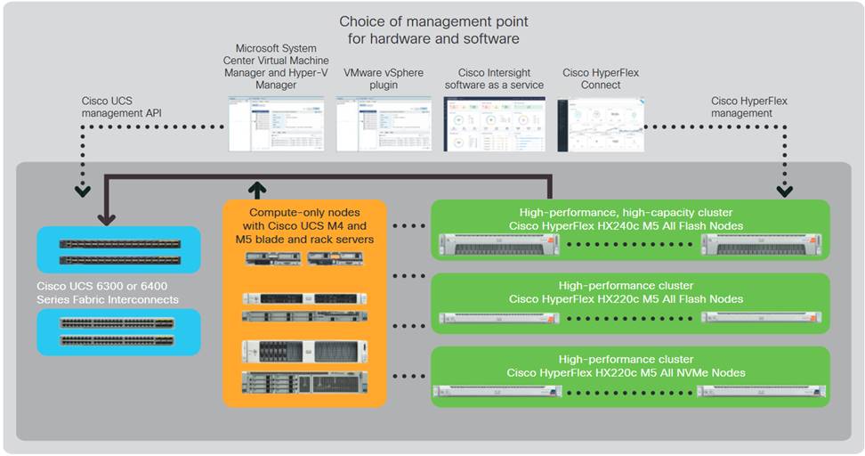
Cisco HyperFlex Systems are designed with an end-to-end software-defined infrastructure that eliminates the compromises found in first-generation products. Cisco HyperFlex Systems combine software-defined computing in the form of Cisco UCS® servers, software-defined storage with the powerful Cisco HyperFlex HX Data Platform Software, and software-defined networking (SDN) with the Cisco® unified fabric that integrates smoothly with Cisco Application Centric Infrastructure (Cisco ACI™). With All-NVMe memory storage configurations, and a choice of management tools, Cisco HyperFlex Systems deliver a pre-integrated cluster that is up and running in an hour or less and that scales resources independently to closely match your application resource needs (Figure 1).
Figure 1. Cisco HyperFlex Systems Offer Next-Generation Hyperconverged Solutions
The Cisco HyperFlex Data Platform includes:
● Enterprise-class data management features that are required for complete lifecycle management and enhanced data protection in distributed storage environments—including replication, always on inline deduplication, always on inline compression, thin provisioning, instantaneous space efficient clones, and snapshots.
● Simplified data management that integrates storage functions into existing management tools, allowing instant provisioning, cloning, and pointer-based snapshots of applications for dramatically simplified daily operations.
● Improved control with advanced automation and orchestration capabilities and robust reporting and analytics features that deliver improved visibility and insight into IT operation.
● Independent scaling of the computing and capacity tiers, giving you the flexibility to scale out the environment based on evolving business needs for predictable, pay-as-you-grow efficiency. As you add resources, data is automatically rebalanced across the cluster, without disruption, to take advantage of the new resources.
● Continuous data optimization with inline data deduplication and compression that increases resource utilization with more headroom for data scaling.
● Dynamic data placement optimizes performance and resilience by making it possible for all cluster resources to participate in I/O responsiveness. All-NVMe nodes use nvme flash drives for caching layer as well as capacity layer. This approach helps eliminate storage hotspots and makes the performance capabilities of the cluster available to every virtual machine. If a drive fails, reconstruction can proceed quickly as the aggregate bandwidth of the remaining components in the cluster can be used to access data.
● Compute-only nodes, powered by the latest Intel generations of CPUs, provide enormous compute resources required by performance sensitive applications like databases.
● Low latency and lossless 25G and 40G unified Ethernet networking backed by Cisco UCS 6400 and 6300 Series Fabric Interconnects which increase the reliability, efficiency, and scalability of Ethernet networks.
● Native iSCSI feature enables HyperFlex clusters to support new use cases that require block storage or shared disk access. Microsoft SQL Server Failover Cluster instance (FCI) is one such applications that can leverage HyperFlex iSCSI feature for shared disk access and providing better high availability to critical database deployments.
● Enterprise data protection with a highly-available, self-healing architecture that supports non-disruptive, rolling upgrades and offers call-home and onsite 24x7 support options.
● API-based data platform architecture that provides data virtualization flexibility to support existing and new cloud-native data types.
● Cisco Intersight is the latest visionary cloud-based management tool, designed to provide a centralized off-site management, monitoring, and reporting tool for all your Cisco UCS based solutions including HyperFlex Cluster.
Architecture
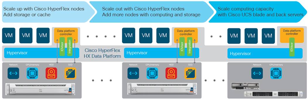
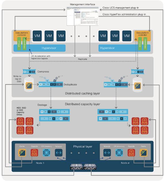
In Cisco HyperFlex Systems, the data platform spans three or more Cisco HyperFlex HX-Series nodes to create a highly available cluster. Each node includes a Cisco HyperFlex HX Data Platform controller that implements the scale-out and distributed file system using internal SSD/NVMe drives to store data. The controllers communicate with each other over 25 or 40 Gigabit Ethernet to present a single pool of storage that spans the nodes in the cluster (Figure 2). Nodes access data through a data layer using file, block, object, and API plug-ins. As nodes are added, the cluster scales linearly to deliver computing, storage capacity, and I/O performance.
Figure 2. Distributed Cisco HyperFlex System
In the VMware vSphere environment, the controller occupies a virtual machine with a dedicated number of processor cores and amount of memory, allowing it to deliver consistent performance and not affect the performance of the other virtual machines on the cluster. The controller can access all storage without hypervisor intervention through the VMware VM_DIRECT_PATH feature. In the All-Flash or All-NVMe configuration, the controller uses the node’s memory, a dedicated SSD/NVMe drive for write logging, and other SSDs/NVMe drives for distributed capacity storage. The controller integrates the data platform into VMware software using two preinstalled VMware ESXi vSphere Installation Bundles (VIBs):
● IO Visor: This VIB provides a network file system (NFS) mount point so that the VMware ESXi hypervisor can access the virtual disk drives that are attached to individual virtual machines. From the hypervisor’s perspective, it is simply attached to a network file system.
● VMware Storage API for Array Integration (VAAI): This storage offload API allows VMWare vSphere to request advanced file system operations such as snapshots and cloning. The controller causes these operations to occur through manipulation of metadata rather than actual data copying, providing rapid response, and thus rapid deployment of new application environments.
Physical Architecture
Cisco Unified Computing System
The Cisco Unified Computing System (Cisco UCS) is a next-generation data center platform that unites compute, network, and storage access. The platform, optimized for virtual environments, is designed using open industry-standard technologies and aims to reduce the total cost of ownership (TCO) and increase the business agility. The system integrates a low-latency; lossless 25 or 40Gigabit Ethernet unified network fabric with enterprise-class, x86-architecture servers. It is an integrated, scalable, multi-chassis platform in which all resources participate in a unified management domain.
Cisco Unified Computing System consists of the following components:
● Compute - The system is based on an entirely new class of computing system that incorporates rack mount and blade servers based on Intel® Xeon® scalable processors product family.
● Network - The system is integrated onto a low-latency, lossless, 25 or 40-Gbps unified network fabric. This network foundation consolidates Local Area Networks (LAN’s), Storage Area Networks (SANs), and high-performance computing networks which are separate networks today. The unified fabric lowers costs by reducing the number of network adapters, switches, and cables, and by decreasing the power and cooling requirements.
● Virtualization - The system unleashes the full potential of virtualization by enhancing the scalability, performance, and operational control of virtual environments. Cisco security, policy enforcement, and diagnostic features are now extended into virtualized environments to better support changing business and IT requirements.
● Storage access - The system provides consolidated access to both SAN storage and Network Attached Storage (NAS) over the unified fabric. It is also an ideal system for Software Defined Storage (SDS). Combining the benefits of single framework to manage both the compute and Storage servers in a single pane, Quality of Service (QOS) can be implemented if needed to inject IO throttling in the system. In addition, the server administrators can pre-assign storage-access policies to storage resources, for simplified storage connectivity and management leading to increased productivity. In addition to external storage, both rack and blade servers have internal storage which can be accessed through built-in hardware RAID controllers. With storage profile and disk configuration policy configured in Cisco UCS Manager, storage needs for the host OS and application data gets fulfilled by user defined RAID groups for high availability and better performance.
● Management - the system uniquely integrates all system components to enable the entire solution to be managed as a single entity by Cisco UCS Manager (UCSM). Cisco UCS Manager has an intuitive graphical user interface (GUI), a command-line interface (CLI), and a powerful scripting library module for Microsoft PowerShell built on a robust application programming interface (API) to manage all system configuration and operations.
Cisco Unified Computing System is designed to deliver:
● Reduced Total Cost of Ownership and increased business agility.
● Increased IT staff productivity through just-in-time provisioning and mobility support.
● A cohesive, integrated system which unifies the technology in the data center. The system is managed and tested.
● Scalability through a design for hundreds of discrete servers and thousands of virtual machines and the capability to scale I/O bandwidth to match the demand.
● Industry standard supported by a partner ecosystem of industry leaders.
Cisco Fabric Interconnects
The Cisco UCS Fabric Interconnect (FI) is a core part of Cisco Unified Computing System, providing both network connectivity and management capabilities for the system. Both Cisco UCS 6400 and 6300 Series Fabric Interconnects are supported. Depending on the model chosen, the Cisco UCS Fabric Interconnect offers line-rate, low-latency, lossless 25 Gigabit or 40 Gigabit Ethernet, Fibre Channel over Ethernet (FCoE) and Fibre Channel connectivity. Cisco UCS Fabric Interconnects provide the management and communication backbone for the Cisco UCS C-Series, S-Series, and HX-Series Rack-Mount Servers, Cisco UCS B-Series Blade Servers, and Cisco UCS 5100 Series Blade Server Chassis. All servers and chassis, and therefore all blades, attached to the Cisco UCS Fabric Interconnects become part of a single, highly available management domain. In addition, by supporting unified fabrics, the Cisco UCS Fabric Interconnects provide both the LAN and SAN connectivity for all servers within its domain.
The Cisco UCS 6454 54-Port Fabric Interconnect is a One-Rack-Unit (1RU) 10/25/40/100 Gigabit Ethernet, FCoE and Fibre Channel switch offering up to 3.82 Tbps throughput and up to 54 ports. The switch has 36 10/25-Gbps Ethernet ports, 4 1/10/25-Gbps Ethernet ports, 6 40/100-Gbps Ethernet uplink ports and 8 unified ports that can support 8 10/25-Gbps Ethernet ports or 8/16/32-Gbps Fibre Channel ports. All Ethernet ports are capable of supporting FCoE.
The Cisco UCS 6332-16UP Fabric Interconnect is a one-rack-unit (1RU) 10/40 Gigabit Ethernet, FCoE, and native Fibre Channel switch offering up to 2430 Gbps of throughput. The switch has 24 40-Gbps fixed Ethernet and FCoE ports, plus 16 1/10-Gbps fixed Ethernet, FCoE, or 4/8/16 Gbps FC ports. Up to 18 of the 40-Gbps ports can be reconfigured as 4x10Gbps breakout ports, providing up to 88 total 10-Gbps ports, although Cisco HyperFlex nodes must use a 40GbE VIC adapter in order to connect to a Cisco UCS 6300 Series Fabric Interconnect.
The Cisco UCS 6332 Fabric Interconnect is a one-rack-unit (1RU) 40 Gigabit Ethernet and FCoE switch offering up to 2560 Gbps of throughput. The switch has 32 40-Gbps fixed Ethernet and FCoE ports. Up to 24 of the ports can be reconfigured as 4x10Gbps breakout ports, providing up to 96 10-Gbps ports, although Cisco HyperFlex nodes must use a 40GbE VIC adapter in order to connect to a Cisco UCS 6300 Series Fabric Interconnect.
Cisco HyperFlex HX-Series Nodes
A standard HyperFlex cluster requires a minimum of three HX-Series “converged” nodes (with disk storage). Data is replicated across at least two of these nodes, and a third node is required for continuous operation in the event of a single-node failure. Each node that has disk storage is equipped with at least one high-performance NVMe or SSD drive for data caching and rapid acknowledgment of write requests. Each node also is equipped with additional disks, up to the platform’s physical limit, for long term storage and capacity.
Cisco HyperFlex HXAF220c-M5N All-NVMe Node
This small footprint Cisco HyperFlex All-NVMe model contains a 240 GB M.2 form factor solid-state disk (SSD) that acts as the boot drive, a 1 TB housekeeping NVMe SSD drive, a single 375 GB Intel Optane NVMe SSD write-log drive, and six to eight 1 TB or 4 TB NVMe SSD drives for storage capacity. Optionally, the Cisco HyperFlex Acceleration Engine card can be added to improve write performance and compression. Self-encrypting drives are not available as an option for the All-NVMe nodes.
Figure 3. HXAF 220c-M5N All-NVMe node

Cisco HyperFlex Compute-Only Nodes
All current model Cisco UCS M4 and M5 generation servers, except the Cisco UCS C880 M4 and Cisco UCS C880 M5, may be used as compute-only nodes connected to a Cisco HyperFlex cluster, along with a limited number of previous M3 generation servers. Any valid CPU and memory configuration is allowed in the compute-only nodes, and the servers can be configured to boot from SAN, local disks, or internal SD cards. Below is the list of some M5 servers that may be used as compute-only nodes:
● Cisco UCS B200 M5 Blade Server
● Cisco UCS B480 M5 Blade Server
● Cisco UCS C220 M5 Rack Mount Servers
● Cisco UCS C240 M5 Rack Mount Servers
● Cisco UCS C480 M5 Rack Mount Servers
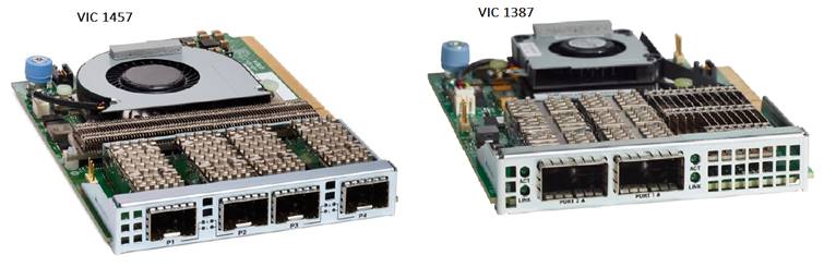
Cisco UCS VIC 1457 and 1387 mLOM Interface Cards
The Cisco UCS VIC 1457 is a quad-port Small Form-Factor Pluggable (SFP28) mLOM card designed for the M5 generation of Cisco UCS C-Series Rack Servers. The card supports 10-Gbps or 25-Gbps Ethernet and FCoE, where the speed of the link is determined by the model of SFP optics or cables used. The card can be configured to use a pair of single links, or optionally to use all four links as a pair of bonded links. The Cisco UCS VIC 1457 is used in conjunction with the Cisco UCS 6454 model Fabric Interconnect.
The Cisco UCS VIC 1387 Card is a dual-port Enhanced Quad Small Form-Factor Pluggable (QSFP+) 40-Gbps Ethernet, and Fibre Channel over Ethernet (FCoE)-capable PCI Express (PCIe) modular LAN-on-motherboard (mLOM) adapter installed in the Cisco UCS HX-Series Rack Servers. The Cisco UCS VIC 1387 is used in conjunction with the Cisco UCS 6332 or 6332-16UP model Fabric Interconnects.
The mLOM slot can be used to install a Cisco VIC without consuming a PCIe slot, which provides greater I/O expandability. It incorporates next-generation converged network adapter (CNA) technology from Cisco, providing investment protection for future feature releases. The card enables a policy-based, stateless, agile server infrastructure that can present up to 256 PCIe standards-compliant interfaces to the host, each dynamically configured as either a network interface card (NICs) or host bus adapter (HBA). The personality of the interfaces is set programmatically using the service profile associated with the server. The number, type (NIC or HBA), identity (MAC address and World-Wide Name [WWN]), failover policy, adapter settings, bandwidth, and quality-of-service (QoS) policies of the PCIe interfaces are all specified using the service profile.
Figure 4. Cisco VIC 1457 mLOM and 1387 mLOM
Cisco HyperFlex Systems Details
Engineered on the successful Cisco UCS platform, Cisco HyperFlex Systems deliver a hyperconverged solution that truly integrates all components in the data center infrastructure—compute, storage, and networking. The HX Data Platform starts with three or more nodes to form a highly available cluster. Each of these nodes has a software controller called the Cisco HyperFlex Controller. It takes control of the internal locally installed drives to store persistent data into a single distributed, multitier, object-based data store. The controllers communicate with each other over low-latency 25 or 40 Gigabit Ethernet fabric, to present a single pool of storage that spans across all the nodes in the cluster so that data availability is not affected if single or multiple components fail.
Data Distribution (NFS)
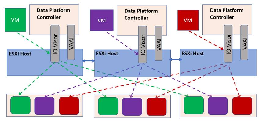
Incoming data is distributed across all nodes in the cluster to optimize performance using the caching tier (Figure 5). Effective data distribution is achieved by mapping incoming data to stripe units that are stored evenly across all nodes, with the number of data replicas determined by the policies you set. For each write operation, the data is intercepted by the IO Visor module on the node where the VM is running, a primary node is determined for that particular operation via a hashing algorithm, and then sent to the primary node via the network. The primary node compresses the data in real time, writes the compressed data to the write log on its caching SSD, and replica copies of that compressed data are sent via the network and written to the write log on the caching SSD of the remote nodes in the cluster, according to the replication factor setting. For example, at RF=3 a write operation will be written to write log of the primary node for that virtual disk address, and two additional writes will be committed in parallel on two other nodes. Because the virtual disk contents have been divided and spread out via the hashing algorithm for each unique operation, this method results in all writes being spread across all nodes, avoiding the problems with data locality and “noisy” VMs consuming all the IO capacity of a single node. The write operation will not be acknowledged until all three copies are written to the caching layer SSDs. Written data is also cached in a write log area resident in memory in the controller VM, along with the write log on the caching SSDs. This process speeds up read requests when reads are requested of data that has recently been written. This contrasts with other architectures that use a data locality approach that does not fully use available networking and I/O resources and is vulnerable to hot spots. When moving a virtual machine to a new location using tools such as VMware Dynamic Resource Scheduling (DRS), the Cisco HyperFlex HX Data Platform does not require data to be moved. This approach significantly reduces the impact and cost of moving virtual machines among systems.
Figure 5. Data Distribution for NFS in HXDP
For data distribution for iSCSI, go to section HyperFlex Native iSCSI Storage.
Data Operations
The data platform implements a distributed, log-structured file system that changes how it handles caching and storage capacity depending on the node configuration.
In the All-Flash/All-NVMe configuration, the data platform uses a caching layer in SSD/NVMe disk to accelerate write responses, and it implements the capacity layer in SSDs/NVMe drives. Read requests are fulfilled directly from data obtained from the SSD/NVMe drives in the capacity layer. A dedicated read cache is not required to accelerate read operations.
Incoming data is striped across the number of nodes required to satisfy availability requirements—usually two or three nodes. Based on policies you set, incoming write operations are acknowledged as persistent after they are replicated to the SSD/NVMe drives in other nodes in the cluster. This approach reduces the likelihood of data loss due to SSD/NVMe disk or node failures. The write operations are then de-staged to SSD/NVMe disks in the capacity layer in the All-NVMe configuration for long-term storage.
The log-structured file system writes sequentially to one of two write logs (three in case of RF=3) until it is full. It then switches to the other write log while de-staging data from the first to the capacity tier. When existing data is (logically) overwritten, the log-structured approach simply appends a new block and updates the metadata. This layout benefits SSD/NVMe configurations in which seek operations are not time consuming. It reduces the write amplification levels of SSD/NVMe disk and the total number of writes the flash media experiences due to incoming writes and random overwrite operations of the data.
When data is de-staged to the capacity tier in each node, the data is deduplicated and compressed. This process occurs after the write operation is acknowledged, so no performance penalty is incurred for these operations. A small deduplication block size helps increase the deduplication rate. Compression further reduces the data footprint. Data is then moved to the capacity tier as write cache segments are released for reuse (Figure 6).
Figure 6. Data Distribution in HXDP
Hot data sets—data that are frequently or recently read from the capacity tier are cached in memory. Unlike Hybrid configurations, All-NVMe and All-Flash configurations do not use an NVMe, or SSD read cache since there are no performance benefits using a cache; the persistent data copy already resides on the high-performance SSD drives. In these configurations, a read cache implemented with NVMe or SSDs could become a bottleneck and prevent the system from using the aggregate bandwidth of the entire set of capacity drives.
Data Optimization
The Cisco HyperFlex HX Data Platform provides a finely detailed inline deduplication and variable block inline compression that is always on for objects in the cache (NVMe/SSD and memory) and capacity (SSD/NVMe) layers. Unlike other solutions, which require you to turn off these features to maintain performance, the deduplication and compression capabilities in the Cisco data platform are designed to sustain and enhance performance and significantly reduce physical storage capacity requirements.
Data Deduplication
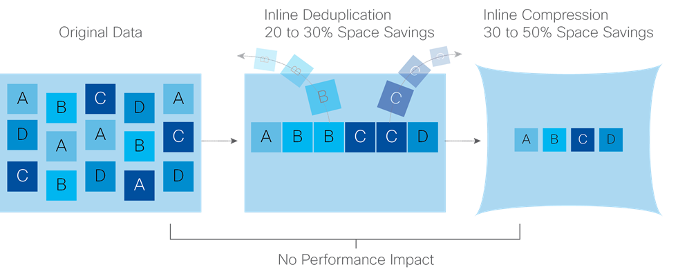
Data deduplication is used on all storage in the cluster, including memory and NVMe/SSD drives. Based on a patent-pending Top-K Majority algorithm, the platform uses conclusions from empirical research that show that most data, when sliced into small data blocks, has significant deduplication potential based on a minority of the data blocks. By fingerprinting and indexing just these frequently used blocks, high rates of deduplication can be achieved with only a small amount of memory, which is a high-value resource in cluster nodes (Figure 7).
Figure 7. HyperFlex Data Platform Optimizes Data Storage with No Performance Impact
Inline Compression
The Cisco HyperFlex HX Data Platform uses high-performance inline compression on data sets to save storage capacity. Although other products offer compression capabilities, many negatively affect performance. In contrast, the Cisco data platform uses CPU-offload instructions to reduce the performance impact of compression operations. In addition, the log-structured distributed-objects layer has no effect on modifications (write operations) to previously compressed data. Instead, incoming modifications are compressed and written to a new location, and the existing (old) data is marked for deletion, unless the data needs to be retained in a snapshot.
The data that is modified does not need to be read prior to the write operation. This feature avoids typical read-modify-write penalties and significantly improves write performance.
Log-Structured Distributed Objects
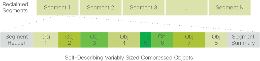
In the Cisco HyperFlex HX Data Platform, the log-structured distributed-object store layer groups and compresses data that filters through the deduplication engine into self-addressable objects. These objects are written to disk in a log-structured, sequential manner. All incoming I/O—including random I/O—is written sequentially to both the caching (NVMe/SSD and memory) and persistent tiers. The objects are distributed across all nodes in the cluster to make uniform use of storage capacity.
By using a sequential layout, the platform helps increase flash-memory endurance. Because read-modify-write operations are not used, there is little or no performance impact of compression, snapshot operations, and cloning on overall performance.
Data blocks are compressed into objects and sequentially laid out in fixed-size segments, which in turn are sequentially laid out in a log-structured manner (Figure 8). Each compressed object in the log-structured segment is uniquely addressable using a key, with each key fingerprinted and stored with a checksum to provide high levels of data integrity. In addition, the chronological writing of objects helps the platform quickly recover from media or node failures by rewriting only the data that came into the system after it was truncated due to a failure.
Figure 8. HyperFlex Data Platform Optimizes Data Storage with No Performance Impact
Encryption
Securely encrypted storage optionally encrypts both the caching and persistent layers of the data platform. Integrated with enterprise key management software, or with passphrase-protected keys, encrypting data at rest helps you comply with HIPAA, PCI-DSS, FISMA, and SOX regulations. The platform itself is hardened to Federal Information Processing Standard (FIPS) 140-1 and the encrypted drives with key management comply with the FIPS 140-2 standard.
Data Services
The Cisco HyperFlex HX Data Platform provides a scalable implementation of space-efficient data services, including thin provisioning, space reclamation, pointer-based snapshots, and clones—without affecting performance.
Thin Provisioning
The platform makes efficient use of storage by eliminating the need to forecast, purchase, and install disk capacity that may remain unused for a long time. Virtual data containers can present any amount of logical space to applications, whereas the amount of physical storage space that is needed is determined by the data that is written. You can expand storage on existing nodes and expand your cluster by adding more storage-intensive nodes as your business requirements dictate, eliminating the need to purchase large amounts of storage before you need it.
Snapshots
The Cisco HyperFlex HX Data Platform uses metadata-based, zero-copy snapshots to facilitate backup operations and remote replication: critical capabilities in enterprises that require always-on data availability. Space efficient snapshots allow you to perform frequent online backups of data without needing to worry about the consumption of physical storage capacity. Data can be moved offline or restored from these snapshots instantaneously:
● Fast snapshot updates: When modified-data is contained in a snapshot, it is written to a new location, and the metadata is updated, without the need for read-modify-write operations.
● Rapid snapshot deletions: You can quickly delete snapshots. The platform simply deletes small number of metadata that is located on an SSD, rather than performing a long consolidation process as needed by solutions that use a delta-disk technique.
● Highly specific snapshots: With the Cisco HyperFlex HX Data Platform, you can take snapshots on an individual file basis. In virtual environments, these files map to drives in a virtual machine. This flexible specificity allows you to apply different snapshot policies on different virtual machines.
Full featured backup applications, such as Veeam Backup and Replication, can limit the amount of throughput the backup application can consume which can protect latency sensitive applications during the production hours. With the release of v9.5 update 2, Veeam is the first partner to integrate HX native snapshots into the product. HX Native snapshots do not suffer the performance penalty of delta-disk snapshots, and do not require heavy disk IO impacting consolidation during snapshot deletion.
Particularly important for SQL administrators is the Veeam Explorer for SQL: https://www.veeam.com/sharepoint-ad-sql-exchange-recovery-explorer.html, which can provide transaction level recovery within the Microsoft VSS framework. The three ways Veeam Explorer for SQL Server works to restore SQL Server databases include: From the backup restore point, from a log replay to a point in time, and from a log replay to a specific transaction – all without taking the VM or SQL Server offline.
Fast, Space-Efficient Clones
In the Cisco HyperFlex HX Data Platform, clones are writable snapshots that can be used to rapidly provision items such as virtual desktops and applications for test and development environments. These fast, space-efficient clones rapidly replicate storage volumes so that virtual machines can be replicated through just metadata operations, with actual data copying performed only for write operations. With this approach, hundreds of clones can be created and deleted in minutes. Compared to full-copy methods, this approach can save a significant amount of time, increase IT agility, and improve IT productivity.
Clones are deduplicated when they are created. When clones start diverging from one another, data that is common between them is shared, with only unique data occupying new storage space. The deduplication engine eliminates data duplicates in the diverged clones to further reduce the clone’s storage footprint.
Data Replication and Availability
In the Cisco HyperFlex HX Data Platform, the log-structured distributed-object layer replicates incoming data, improving data availability. Based on policies that you set, data that is written to the write cache is synchronously replicated to one or two other NVMe/SSD drives located in different nodes before the write operation is acknowledged to the application. This approach allows incoming writes to be acknowledged quickly while protecting data from NVMe/SSD or node failures. If an NVMe/SSD or node fails, the replica is quickly recreated on other NVMe/SSD drives or nodes using the available copies of the data.
The log-structured distributed-object layer also replicates data that is moved from the write cache to the capacity layer. This replicated data is likewise protected from SSD or node failures. With two replicas, or a total of three data copies, the cluster can survive uncorrelated failures of two SSD drives or two nodes without the risk of data loss. Uncorrelated failures are failures that occur on different physical nodes. Failures that occur on the same node affect the same copy of data and are treated as a single failure. For example, if one disk in a node fails and subsequently another disk on the same node fails, these correlated failures count as one failure in the system. In this case, the cluster could withstand another uncorrelated failure on a different node. See the Cisco HyperFlex HX Data Platform system administrator’s guide for a complete list of fault-tolerant configurations and settings.
If a problem occurs in the Cisco HyperFlex HX controller software, data requests from the applications residing in that node are automatically routed to other controllers in the cluster. This same capability can be used to upgrade or perform maintenance on the controller software on a rolling basis without affecting the availability of the cluster or data. This self-healing capability is one of the reasons that the Cisco HyperFlex HX Data Platform is well suited for production applications.
In addition, native replication transfers consistent cluster data to local or remote clusters. With native replication, you can snapshot and store point-in-time copies of your environment in local or remote environments for backup and disaster recovery purposes.
HyperFlex VM Replication
HyperFlex Replication copies the virtual machine’s snapshots from one Cisco HyperFlex cluster to another Cisco HyperFlex cluster to facilitate recovery of protected virtual machines from a cluster or site failure, via failover to the secondary site.
Data Rebalancing
A distributed file system requires a robust data rebalancing capability. In the Cisco HyperFlex HX Data Platform, no overhead is associated with metadata access, and rebalancing is extremely efficient. Rebalancing is a non-disruptive online process that occurs in both the caching and persistent layers, and data is moved at a fine level of specificity to improve the use of storage capacity. The platform automatically rebalances existing data when nodes and drives are added or removed or when they fail. When a new node is added to the cluster, its capacity and performance is made available to new and existing data. The rebalancing engine distributes existing data to the new node and helps ensure that all nodes in the cluster are used uniformly from capacity and performance perspectives. If a node fails or is removed from the cluster, the rebalancing engine rebuilds and distributes copies of the data from the failed or removed node to available nodes in the clusters.
Online Upgrades
Cisco HyperFlex HX-Series systems and the HX Data Platform support online upgrades so that you can expand and update your environment without business disruption. You can easily expand your physical resources; add processing capacity; and download and install BIOS, driver, hypervisor, firmware, and Cisco UCS Manager updates, enhancements, and bug fixes.
HyperFlex Native iSCSI Storage
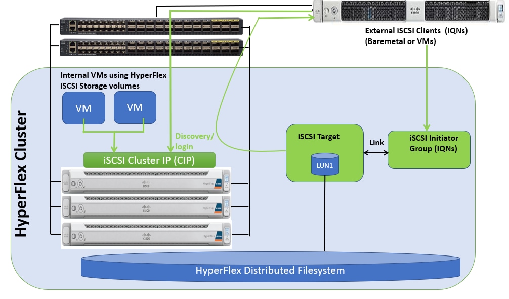
Cisco HyperFlex 4.5 introduces the ability to present internal storage capacity from the Hyperflex distributed filesystem to external servers or VMs via the Internet Small Computer Systems Interface (iSCSI) protocol. Presenting storage via iSCSI differs from the standard storage presentation in HyperFlex, in that HXDP normally stores virtual disk files for VMs on its internal distributed NFS-based filesystem, whereas iSCSI presents raw block-based storage devices to external clients via an IP network. These external clients can be configured with hardware or software-based iSCSI initiators, each with a unique iSCSI Qualified Name (IQN). The external clients communicate with the HyperFlex cluster via their initiators over a dedicated IP network to mount the presented storage devices, which appear to the clients as a standard raw block-based disk. In truth, the mounted storage devices are virtualized, drawn from the overall HXDP filesystem via software and the data is distributed across the entire HyperFlex cluster. The external clients can truly be external servers or VMs running in other systems but could also be VMs running within the HyperFlex cluster itself. Common uses for iSCSI mounted storage include database systems, email systems and other clustered solutions, which commonly need simultaneous shared access to raw disk devices for shared data, logs, or quorum devices. Additionally, iSCSI storage can be used when external clients simply need additional storage space but adding more physical storage to the systems themselves is not practical or possible, and also for Kubernetes persistent volumes.
From the Hyperflex Connect management webpage, the HyperFlex cluster can be configured with additional IP addresses within a dedicated VLAN for connectivity; one for the cluster and one more for each of the individual nodes. These addresses become the endpoints for connections from the external clients to send iSCSI based I/O traffic from their iSCSI initiators. Within HyperFlex, iSCSI Targets are created, and within each target one or more Logical Unit Numbers (LUNs) are created, essentially a numbered device which appear to the external clients as raw block storage devices. To control device access to the hosts, Initiator Groups are created which list the unique IQNs of one or more initiators which need to access a LUN. Initiator Groups and Targets are then linked with each other, working as a form of masking to define which initiators can access the presented LUNs. In addition, authentication using Challenge-Handshake Authentication Protocol (CHAP) can be configured to require password-based authentication to the devices.
Figure 9 details the logical design for iSCSI storage presentation from a Cisco HyperFlex cluster:
Figure 9. iSCSI Logical Diagram
SQL Server Deployment Options using iSCSI Volumes
This section details various SQL Server deployment options using HyperFlex native iSCSI feature.
● Microsoft SQL Server Failover Cluster Instance (FCI) with in the HyperFlex Cluster: Customers can leverage HyperFlex shared iSCSI volumes and Microsoft SQL Server Failover Cluster Instances (FCI) to provide additional availability to the critical databases hosted with in the same HyperFlex Cluster. This helps customers to meet the required RTO (Recovery Time Objective) for critical databases hosted with in the HyperFlex cluster.
● Microsoft SQL Server Standalone or Failover Cluster Instance (FCI) outside the HyperFlex Cluster: Since HyperFlex iSCSI volumes can be exposed to any client that has connectivity to the HyperFlex iSCSI network, customers can use HyperFlex iSCSI volumes as storage layer for deploying standalone or Clustered SQL Server Instances hosted outside the HyperFlex Cluster. These deployments can be either bare-metal or virtualized SQL environments.
iSCSI Storage Clones
HyperFlex iSCSI feature also supports cloning of iSCSI volumes. Crash-consistent or Application consistent copies of existing iSCSI volumes can be created and can be mounted to different clients as iSCSI volumes. This feature allows customers to quickly refresh databases in test/development environments with Production databases. This saves lot of time for application owners and databases administrators by automating database refresh activities using iSCSI cloning feature.
HyperFlex All-NVMe Systems for SQL Server Database Deployments
SQL server database systems act as the backend to many performance critical applications. It is very important to ensure that it is highly available and delivers consistent performance with predictable latency throughout. The following are some of the major advantages of Cisco HyperFlex All-NVMe hyperconverged systems which makes it ideally suited for SQL Server database implementations:
● Low latency with consistent performance: Cisco HyperFlex All-NVMe nodes provides excellent platform for critical database deployment by offering low latency, consistent performance and exceeds most of the database service level agreements.
● Data protection (fast clones and snapshots, replication factor, VM replication and Stretched Cluster): The HyperFlex systems are engineered with robust data protection techniques that enable quick backup and recovery of the applications in case of any failures.
● Storage optimization: All the data that comes in the HyperFlex systems are by default optimized using inline deduplication and data compression techniques. Additionally, the HX Data Platform’s log-structured file system ensures data blocks are written to flash devices in a sequential manner thereby increasing flash-memory endurance. HX System makes efficient use of flash storage by using Thin Provisioning storage optimization technique.
● Performance and Capacity Online Scalability: The flexible and independent scalability of the capacity and compute tiers of HyperFlex systems provide immense opportunities to adapt to the growing performance demands without any application disruption.
● Native iSCSI Storage and Clones: It presents internal storage capacity from the Hyperflex distributed filesystem to external servers or VMs via the iSCSI protocol as a raw block device. These iSCSI volumes can be shared between two or more hosts enabling HyperFlex clusters to support new use cases which require shared disk access. Microsoft SQL Server Failover Cluster Instance (FCI) can leverage HX shared iSCSI volumes and provide highly available database instances there by improving customer’s Recovery Time Objective (RTO) of critical database deployments. iSCSI volumes can be cloned with in HyperFlex Systems as crash consistent clones. The clones taken from production environments can be linked to Dev/Test environments. This saves lot of time in refreshing Dev/test databases environments with production copies.
● No Performance Hotspots: The distributed architecture of HyperFlex Data Platform ensures that every VM can leverage the storage IOPS and capacity of the entire cluster, irrespective of the physical node it is residing on. This is especially important for SQL Server VMs as they frequently need higher performance to handle bursts of application or user activity.
● Non-disruptive System maintenance: Given Cisco HyperFlex Systems are 'distributed computing and storage' architecture which enables the administrators to perform system maintenance tasks without disruption by rolling upgrades.
● Boost Mode: HyperFlex Boost mode increases the available storage IOPS of HyperFlex cluster. It does by increasing the vCPUs allocated to the storage controller virtual machine by four. It is recommended to leverage the boost mode for database workloads for better performance. For more information on how to enable the Boost mode, refer to: https://www.cisco.com/c/en/us/products/collateral/hyperconverged-infrastructure/hyperflex-hx-series/white-paper-c11-743595.html.
This section details the architectural components of a Cisco HyperFlex solution with VMware ESXi to host Microsoft SQL Server databases in a virtual environment. Figure 10 shows a 4-node Cisco HyperFlex hyperconverged reference architecture consisting of HX-Series All-NVMe rack-mount servers used for validating and testing SQL Server databases as part of this document.
Figure 10. Cisco HyperFlex Reference Architecture using All-NVMe nodes
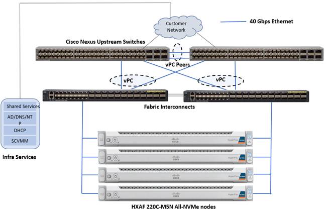
Cisco HyperFlex is composed of a pair of Cisco UCS Fabric Interconnects along with up to a maximum of thirty two HX-Series All-NVMe converged nodes per cluster. Optionally up to a maximum of thirty two compute-only servers can also be added per HyperFlex cluster. Adding Cisco UCS rack-mount servers and/or Cisco UCS 5108 Blade chassis, which house Cisco UCS blade servers allows for additional compute resources in an extended cluster design. Up to eight separate HX clusters can be installed under a single pair of Fabric Interconnects. The two fabric interconnects connect to every HX-Series rack mount server, and connect to every Cisco UCS 5108 blade chassis, and Cisco UCS rack mount server. Upstream network connections, also referred as “north bound” network, are made from the fabric interconnects to the customer datacenter network at the time of installation. In the above reference diagram, a pair of Cisco Nexus 9000 series switches are used and configured as vPC pairs for high availability. For more information about physical connectivity of HX-Series services, compute-only servers, and fabric interconnects to the north bound network, please refer to the Physical Topology section of the Cisco HyperFlex 4.5 for Virtual Server Infrastructure with VMware ESXi CVD.
Infrastructure services such as Active Directory, DNS, NTP and VMWare vCenter are typically installed outside the HyperFlex cluster. Customers can leverage these existing services deploying and managing the HyperFlex cluster.
The HyperFlex storage solution has several data protection techniques, as explained in detail in the Technology overview section, one of which is data replication which needs to be configured on HyperFlex cluster creation. Based on the specific performance and data protection requirements, customer can choose either a replication factor of two (RF2) or three (RF3). For the solution validation (described in the “Solution Testing and Validation” later in this document), we had configured the test HyperFlex cluster with replication factor 3 (RF3).
As described in the earlier Technology Overview section, Cisco HyperFlex distributed file system software runs inside a controller VM, which gets installed on each cluster node. These controller VMs pool and manage all the storage devices and exposes the underlying storage as NFS mount points to the VMware ESXi hypervisors. The ESXi hypervisors expose these NFS mount points as datastores to the guest virtual machines to store their data.
In this document, validation is done on HXAF220c-M5N All-NVMe converged nodes, which act as both compute and storage node. In this solution, 3rd Generation Fabric Interconnects 6332 and VIC 1387 are used for network Fabric. Combination of 4th generation Fabric Interconnects 6454 and VIC1457 can also be used in the solution.
Logical Networking
In the Cisco HyperFlex All-NVMe system, Cisco VIC 1387 is used to provide the required logical network interfaces on each host in the cluster. The communication pathways in the Cisco HyperFlex system can be categorized in to four different traffic zones as described below.
Management Zone: This zone comprises the connections needed to manage the physical hardware, the hypervisor hosts, and the storage platform controller virtual machines (SCVM). These interfaces and IP addresses need to be available to all staff who will administer the HX system, throughout the LAN/WAN. This zone must provide access to Domain Name System (DNS) and Network Time Protocol (NTP) services and allow Secure Shell (SSH) communication. This zone includes multiple physical and virtual components:
● Fabric Interconnect management ports.
● Cisco UCS external management interfaces used by the servers, which answer via the FI management ports.
● ESXi host management interfaces.
● Storage Controller VM management interfaces.
● A roaming HX cluster management interface.
● Storage Controller VM Management interfaces.
VM Zone: This zone is comprised of the connections needed to service network IO to the guest VMs that will run inside the HyperFlex hyperconverged system. This zone typically contains multiple VLANs that are trunked to the Cisco UCS Fabric Interconnects via the network uplinks and tagged with 802.1Q VLAN IDs. These interfaces and IP addresses need to be available to all staff and other computer endpoints which need to communicate with the guest VMs in the HX system, throughout the LAN/WAN.
Storage Zone: This zone comprises the connections used by the Cisco HX Data Platform software, ESXi hosts, and the storage controller VMs to service the HX Distributed Data Filesystem. In addition to the NFS storage network, this zone also comprises iSCSI storage network. Hence, two VLANs are used; one for NFS (hx-storage-data(650)) and other for iSCSI (hx-iscsi(100)). These interfaces and IP addresses always need to be able to communicate with each other for proper operation. During normal operation, this traffic all occurs within the Cisco UCS domain, however there are hardware failure scenarios where this traffic would need to traverse the network northbound of the Cisco UCS domain. For that reason, the VLAN used for HX storage traffic (NFS and iSCSI VLANs) must be able to traverse the network uplinks from the Cisco UCS domain, reaching FI A from FI B, and vice-versa. This zone is primarily jumbo frame traffic therefore jumbo frames must be enabled on the Cisco UCS uplinks. This zone includes multiple components:
● A VMkernel interface used for storage traffic on each ESXi host in the HX cluster.
● Storage Controller VM storage interfaces.
● A roaming Cisco HyperFlex cluster storage interface.
● ISCSI storage IP addresses, one per node and one for the entire cluster, for presenting HXDP storage to external clients via the iSCSI protocol.
VMotion Zone: This zone comprises the connections used by the ESXi hosts to enable vMotion of the guest VMs from host to host. During normal operation, this traffic all occurs within the Cisco UCS domain, however there are hardware failure scenarios where this traffic would need to traverse the network northbound of the Cisco UCS domain. For that reason, the VLAN used for HX vMotion traffic must be able to traverse the network uplinks from the Cisco UCS domain, reaching FI A from FI B, and vice-versa.
By leveraging Cisco UCS vNIC templates, LAN connectivity policies and vNIC placement policies in service profile, eight vNICs are carved out from Cisco VIC 1387 on each HX-Series server for network traffic zones mentioned above. Table 1 lists the vNIC templates and other configuration details used for ESXi host in this solution.
Table 1. vNICs Used in ESXi Host
| vNIC Template Name |
hv-mgmt-a |
hv-mgmt-b |
hv-vmotion-a
|
hv-vmotion-b |
Storage-data-a |
storage-data-b |
vm-network-a |
vm-network-a |
| Purpose |
For Management traffic via Fabric-A |
For Management traffic via Fabric-B |
For VM migration traffic via Fabric-A |
For VM migration traffic via Fabric-B |
For Storage traffic via Fabric-A |
For Storage traffic via Fabric-B |
For VM Management traffic via Fabric-A |
For VM Management traffic via Fabric-B |
| Setting |
Value |
Value |
Value |
Value |
Value |
Value |
Value |
Value |
| Fabric ID |
A |
B |
A |
B |
A |
B |
A |
B |
| Fabric Failover |
Disabled |
Disabled |
Disabled |
Disabled |
Disabled |
Disabled |
Disabled |
Disabled |
| Redundancy Type |
Primary Template |
Secondary Template |
Primary Template |
Secondary Template |
Primary Template |
Secondary Template |
Primary Template |
Secondary Template |
| Target |
Adapter |
Adapter |
Adapter |
Adapter |
Adapter |
Adapter |
Adapter |
Adapter |
| Type |
Updating Template |
Updating Template |
Updating Template |
Updating Template |
Updating Template |
Updating Template |
Updating Template |
Updating Template |
| MTU |
1500 |
1500 |
9000 |
9000 |
9000 |
9000 |
1500 |
1500 |
| MAC Pool |
hv-mgmt-a |
hv-mgmt-b |
hv-vmotion-a |
hv-vmotion-b |
Storage-data-a |
Storage-data-b |
vm-network-a |
vm-network-b |
| QoS Policy |
silver |
silver |
bronze |
bronze |
platinum |
platinum |
gold |
gold |
| Network Control Policy |
HyperFlex-Infra |
HyperFlex-Infra |
HyperFlex-Infra |
HyperFlex-Infra |
HyperFlex-Infra |
HyperFlex-Infra |
HyperFlex-vm |
HyperFlex-vm |
| Connection Policy: VMQ |
Not-set |
Not-set |
Not-set |
Not-set |
Not-set |
Not-set |
Not-set |
Not-set |
| VLANs |
IB-Mgmt (603) |
IB-Mgmt (603) |
hx-vmotion(450) |
hx-vmotion(450) |
hx-storage-data(650) hx-iscsi(100) |
hx-storage-data(650) hx-iscsi(100) |
vm-network(500) |
vm-network(500) |
| Native VLAN |
Not-Set |
Not-Set |
Not-Set |
Not-Set |
Not-Set |
Not-Set |
Not-Set |
Not-Set |
| vNIC created |
hv-mgmt-a |
hv-mgmt-b |
hv-vmotion-a |
hv-vmotion-b |
storage-data-a |
storage-data-b |
vm-network-a |
vm-network-b |
| Adapter name within the ESXi host |
vmnic0 |
vmnic4 |
vmnic3 |
vmnic7 |
vmnic1 |
vmnic5 |
vmnic2 |
vmnic6 |
![]() The iSCSI traffic uses Storage-data-a and Storage-data-b vNIC templates and these vNICs should also be configured with iSCSI VLAN ( hx-iscsi(100)).
The iSCSI traffic uses Storage-data-a and Storage-data-b vNIC templates and these vNICs should also be configured with iSCSI VLAN ( hx-iscsi(100)).
Figure 11 depicts the logical network design of a HX-Series server of HyperFlex cluster.
Figure 11. Logical Network Design of ESXi
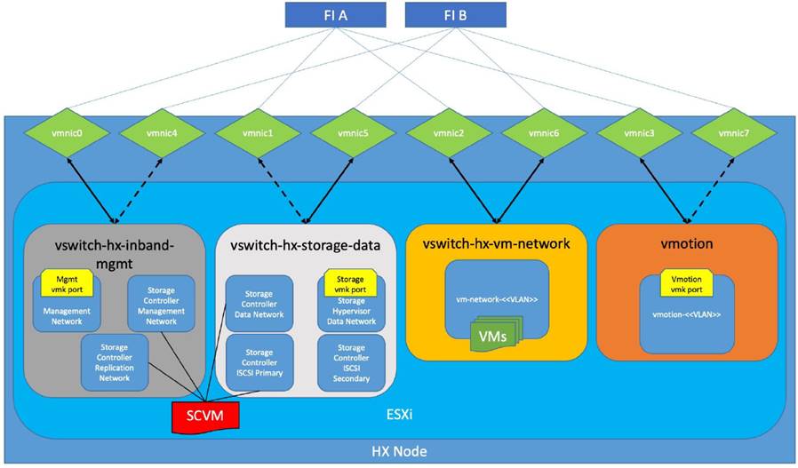
As shown in Figure 11, four virtual standard switches are configured for four traffic zones. Each virtual switch is configured with two vNICs and are connected to both the Fabric Interconnects. The vNICs are configured in active and standby fashion for Storage, Management and vMotion networks. However, vNICs are configured in active-active fashion for VM network. Controller VM is configured with adapters from Management and storage switches. Controller VM is also connected to iSCSI Primary network in the storage-data switch to support the native iSCSI feature.
Jumbo frames are enabled for:
● NFS and iSCSI Storage traffic: Enabling jumbo frames on the Storage traffic zone would benefit IO intensive workloads like SQL databases. With MTU set to 9000 bytes, each IP packet sent carries a larger payload, therefore transmitting more data per packet, and consequently sending and receiving data faster.
● vMotion traffic: Enabling jumbo frames on vMotion traffic zone help the system quickly failover the SQL VMs to other hosts; there by, reducing the overall database downtime.
Creating a separate logical network (using two dedicated vNICs) for guest VMs is beneficial with the following advantages:
● Isolating guest VM traffic from other traffic such as management, HX replication and so on.
● A dedicated MAC pool can be assigned to each vNIC, which would simplify troubleshooting the connectivity issues.
Storage Configuration for SQL Guest VMs
This section discusses storage configuration recommendations for both NFS and iSCSi based volumes.
Storage Configuration recommendations using NFS Datastores
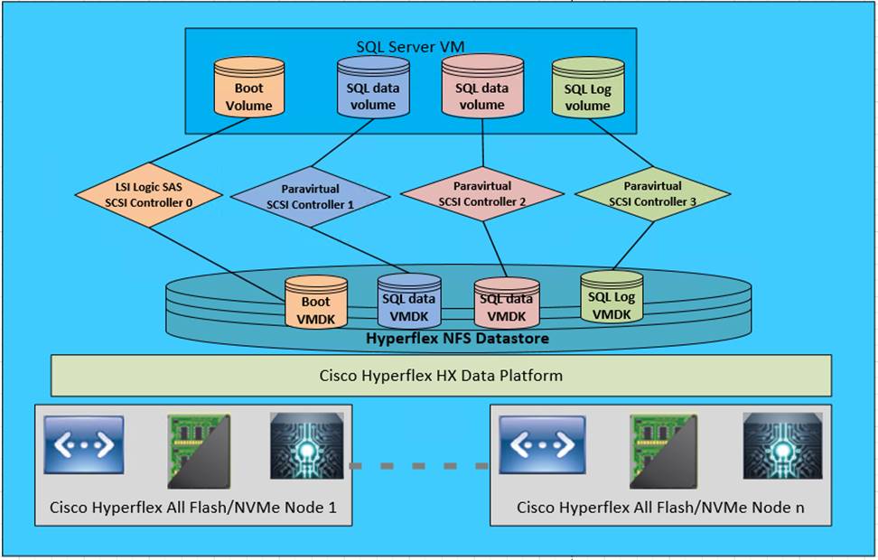
Figure 12 illustrates the NFS storage configuration recommendations for virtual machines running SQL server databases on HyperFlex Cluster. Single LSI Logic virtual SCSI controller is used to host the Guest OS. Separate Paravirtual SCSI (PVSCSI) controllers are configured to host SQL server data and log files. For large scale and high performing SQL deployments, it is recommended to spread the SQL data files across two or more different PVSCSI controllers for better performance as shown in the Figure 12. Additional performance guidelines are detailed in the Deployment Planning section.
Figure 12. Storage Design SQL VMs using NFS based Datastore
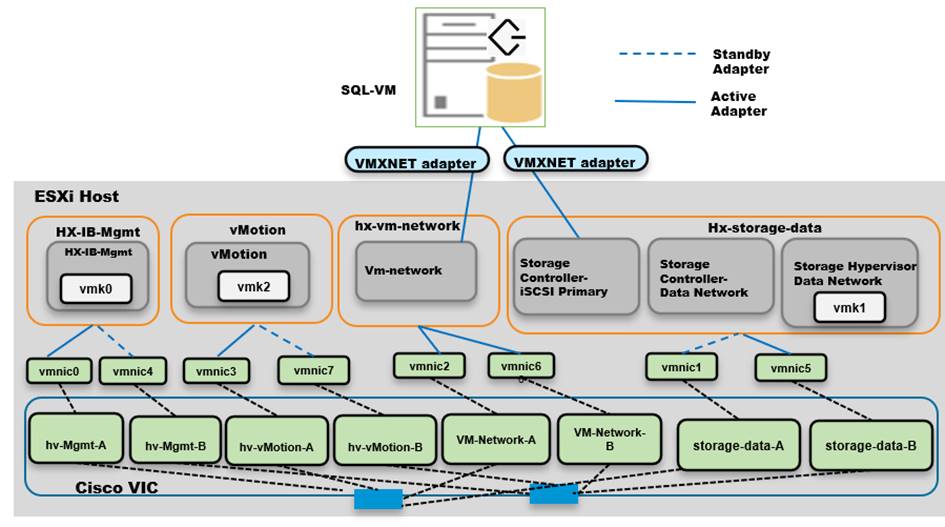
Logical iSCSI Storage Configuration using iSCSI Volumes
Figure 13 illustrates the logical iSCSI storage network configuration for SQL VMs hosted on HyperFlex cluster. SQL VMs configured to connect to the HyperFlex iSCSI network using VMXNET3 network adapter. This adapter is connected to “Storage Controller iSCSI Primary” Port Group located on “hx-storage-data” standard switch of the ESXi host. Set Jumbo frames and assign iSCSI network IP address to the adapter and then connect to HyperFlex iSCSI volumes using Microsoft iSCSI software initiator. Detailed steps for configuring HyperFlex iSCSI network and configuring SQL VM for iSCSI storage connectivity will be discussed in the below sections. These iSCSI volumes are used for storing guest SQL database files. SQL Guest boot volume is stored on traditional HyperFlex NFS Datastore (connected through LSI Logic virtual SCSI controller as shown in Figure 12). SQL VMs are also configured to connect to customer management network using VMXNET3 adapter. This adapter is connected to “vm-network” Port Group of the ESXi host.
Figure 13. Storage Design SQL VMs using iSCSI Volumes
Deployment Planning
It is crucial to follow and implement the configuration best practices and recommendations to achieve optimal performance from any underlying system. This section details the some of the design and configuration best practices that should be followed when deploying SQL server databases on HyperFlex systems All-NVMe or All-Flash Systems. However, it is recommended to test these options before rolling out production deployments to ensure the optimal performance objectives are met.
The following recommendations will be applicable to both NFS and iSCSI deployment until and unless specifically mentioned for particular deployment type:
NFS Datastore Recommendation
These recommendations can be followed while deploying the SQL server virtual machines on HyperFlex Systems:
● All the virtual machine’s virtual disks comprising guest Operating System, SQL data, and transaction log files can be placed on a single datastore exposed as NFS file share to the ESXi hosts. Deploying multiple SQL virtual machines using single datastore simplifies the management tasks.
● There is a maximum queue depth limit of 1024 for each NFS datastore per host, which is an optimum queue depth for most of the workloads. However, when consolidated IO requests from all the virtual machines deployed on the datastore exceeds 1024 (per host limit), then virtual machines might experience higher IO latencies. Symptoms of higher latencies can be identified by monitoring ESXTOP. In such cases, creating new datastore and deploying some of the SQL virtual machines on the new datastore will help. The general recommendation is to deploy low IO demanding SQL virtual machines in one single datastore until high guest latencies are noticed. Also, deploying a dedicated datastore for High IO demanding SQL VMs will allow dedicated queue and hence lesser chances of contention resulting better performance .
SQL Virtual Machine Configuration Recommendation
While creating a SQL Server VM on a HyperFlex system, the following recommendations should be followed for performance and better administration.
● Cores per Socket
NUMA is becoming increasingly more important to ensure workloads, allocate and consume memory within the same physical NUMA node that the vCPUs are scheduled. By changing appropriate Cores per Socket, make sure the virtual machine is configured such that both memory and cpu resources can be met by single physical NUMA. In case of wide virtual machines (demanding more resources than a single physical NUMA), resources can be allocated from two or more physical NUMA groups. For more details on virtual machine configurations best practices with varying resource requirements, please refer to this VMware KB article: https://www.vmware.com/content/dam/digitalmarketing/vmware/en/pdf/solutions/sql-server-on-vmware-best-practices-guide.pdf
● Memory Reservation
SQL server database transactions are usually CPU and memory intensive. In a heavy OLTP database system, it is recommended to reserve all the memory assigned to the SQL virtual machines. This ensures that the assigned memory to the SQL VM is committed and will eliminate the possibility of ballooning and swapping the memory out by the ESXi hypervisor. Memory reservations will have little overhead on the ESXi system. For more information about memory overhead, see Understanding Memory Overhead: https://pubs.vmware.com/vsphere-51/index.jsp?topic=%2Fcom.vmware.vsphere.resmgmt.doc%2FGUID-4954A03F-E1F4-46C7-A3E7-947D30269E34.html
● Paravirtual SCSI adapters for Large-Scale High IO Virtual Machines for NFS deployments
For virtual machines with high disk IO requirements, it is recommended to use Paravirtual SCSI (PVSCSI) adapters. PVSCSI controller is a virtualization aware, high-performance SCSI adapter that allows the lowest possible latency and highest throughput with the lowest CPU overhead. It also has higher queue depth limits compared to other legacy controllers. Legacy controllers (LSI Logic SAS, LSI Logic Parallel and so on) can cause bottleneck and impact database performance; hence not recommended for IO intensive database applications such as SQL server databases.
● Queue Depth and SCSI Controller Recommendations for NFS deployments
Many times, queue depth settings of virtual disks are overlooked, which can impact performance particularly in high IO workloads. Systems such as Microsoft SQL Server databases tend to issue a lot of simultaneous IOs resulting in an insufficient VM driver queue depth setting (default setting is 64 for PVSCSI) to sustain the heavy IOs. It is recommended to change the default queue depth setting to a higher value (up to 254) as suggested in this VMware KB article: https://kb.vmware.com/selfservice/microsites/search.do?language=en_US&cmd=displayKC&externalId=2053145
For large-scale and high IO databases, it is recommended to use multiple virtual disks and have those virtual disks distributed across multiple SCSI controller adapters rather than assigning all of them to a single SCSI controller. This ensures that the guest VM will access multiple virtual SCSI controllers (four SCSI controllers maximum per guest VM), which in turn results in greater concurrency by utilizing the multiple queues available for the SCSI controllers.
● Virtual Machine Network Adapter type
It is highly recommended to configure virtual machine network adapters with “VMXNET 3”. VMXNET 3 is the latest generation of para-virtualized NICs designed for performance. It offers several advanced features including multi-queue support, receive side scaling, IPv4/IPv6 offloads, and MSI/MSI-X interrupt delivery. While creating a new virtual machine, choose “VMXNET 3”.
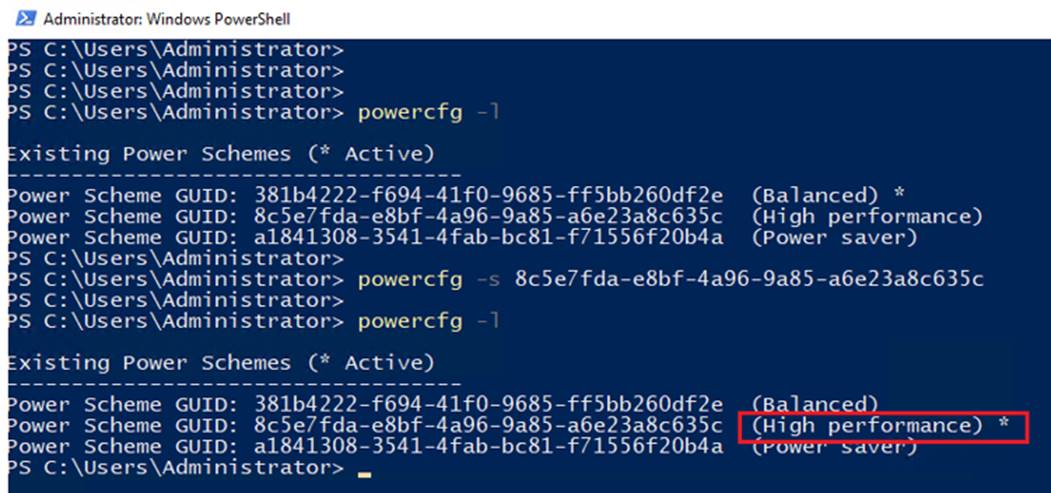
● Guest Power Scheme Settings
Inside the SQL server guest, it is recommended to set the power management option to “High Performance” for optimal database performance as shown in Figure 14. Starting with Windows 2019, the setting High performance is chosen by default.
Figure 14. Changing SQL Guest Power Settings
![]() The ESXi power management option (at vCenter level) is set to “High performance” at the time of the HXDP installation.
The ESXi power management option (at vCenter level) is set to “High performance” at the time of the HXDP installation.
Achieving Database High Availability in Traditional for NFS Deployments
This section describes the high availability techniques to enhance the availability of the virtualized SQL server databases in NFS based HyperFlex deployments.
Cisco HyperFlex storage systems incorporates efficient storage level availability techniques such as data mirroring (Replication Factor 2/3), native snapshot and so on, to make sure continuous data access to the guest VMs hosted on the cluster. For more information about the HX Data Platform Cluster Tolerated Failures, go to: https://www.cisco.com/c/en/us/td/docs/hyperconverged_systems/HyperFlex_HX_DataPlatformSoftware/AdminGuide/4-5/b-hxdp-admin-guide-4-5/m_hxcluster_overview.html#id_13113
In addition to the HyperFlex data availability/protection techniques, the following options can be used to enhance the availability of the virtualized SQL server databases.
● VMWare High Availability
● Microsoft SQL Server native HA features: SQL Server AlwaysOn Availability Group and SQL Server Failover Cluster Instance (FCI)
![]() The Microsoft SQL Server Failover Cluster Instance (FCI) needs shared storage and cannot be deployed using NFS storage (unsupported by VMware ESXi). It can be deployed using HyperFlex iSCSI volumes and it will be discussed later this document.
The Microsoft SQL Server Failover Cluster Instance (FCI) needs shared storage and cannot be deployed using NFS storage (unsupported by VMware ESXi). It can be deployed using HyperFlex iSCSI volumes and it will be discussed later this document.
Single VM / SQL Instance Level High Availability using VMware vSphere HA Feature
Cisco HyperFlex solution leverages VMware clustering to provide availability to the hosted virtual machines. Since the exposed NFS storage is mounted on all the hosts in the cluster, they act as a shared storage environment to help migrate VMs between the hosts. This configuration helps migrate the VMs seamlessly in case of planned as well as unplanned outage. The vMotion vNIC needs to be configured with Jumbo frames for faster guest VM migration. You can find more information in this VMware document: https://docs.vmware.com/en/VMware-vSphere/6.7/vsphere-esxi-vcenter-server-67-availability-guide.pdf
Database Level High Availability using SQL AlwaysOn Availability Group Feature
Introduced in Microsoft SQL Server 2012, AlwaysOn Availability Groups maximizes the availability of a set of user databases for an enterprise. An availability group supports a failover environment for a discrete set of user databases, known as availability databases, that failover together. An availability group supports a set of read-write primary databases and one to eight sets of corresponding secondary databases. Optionally, secondary databases can be made available for read-only access and/or some backup operations. More information on this feature can be found at the Microsoft MSDN here: https://msdn.microsoft.com/en-us/library/hh510230.aspx.
Microsoft SQL Server AlwaysOn Availability Groups take advantage of Windows Server Failover Clustering (WSFC) as a platform technology. WSFC uses a quorum-based approach to monitor the overall cluster health and maximize node-level fault tolerance. The AlwaysOn Availability Groups will get configured as WSFC cluster resources and the availability of the same will depend on the underlying WSFC quorum modes and voting configuration explained here: https://docs.microsoft.com/en-us/sql/sql-server/failover-clusters/windows/wsfc-quorum-modes-and-voting-configuration-sql-server.
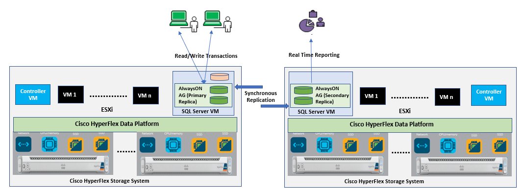
Using AlwaysOn Availability Groups with synchronous replication, supporting automatic failover capabilities, enterprises will be able to achieve seamless database availability across the database replicas configured. The following figure depicts the scenario where an AlwaysOn availability group is configured between the SQL server instances running on two separate HyperFlex Storage systems. To ensure that the involved databases provide guaranteed high performance and no data loss in the event of failure, proper planning need to be done to maintain a low latency replication network link between the clusters.
Figure 15. Synchronous AlwaysOn Configuration Across HyperFlex Systems
Although there are no definitive rules on the infrastructure used for hosting a secondary replica, the following are some of the guidelines if you plan to have a primary replica on the All-NVMe High Performing cluster:
● In case of a synchronous replication (no data loss)
◦ The replicas need to be hosted on similar hardware configurations to ensure that the database performance is not compromised while waiting for the acknowledgment from the replicas.
◦ Ensure a high-speed, low latency network connection between the replicas.
● In case of an asynchronous replication (may have data loss)
◦ The performance of the primary replica does not depend on the secondary replica, so it can be hosted on low cost hardware solutions as well.
◦ The amount of data loss depends on the network characteristics and the performance of the replicas.
If you are willing to deploy AlwaysOn Availability Group within a single HyperFlex cluster, VMWare DRS anti-affinity rules must be used to ensure that each SQL VM replica is placed on different VMware ESXi hosts in order to reduce database downtime. For more details on configuring VMware anti-affinity rules, see: http://pubs.vmware.com/vsphere-60/index.jsp?topic=%2Fcom.vmware.vsphere.resmgmt.doc%2FGUID-7297C302-378F-4AF2-9BD6-6EDB1E0A850A.html.
A Microsoft article describes considerations for deploying Always On availability groups, including prerequisites and restrictions and recommendations for host computers, use of WSFC, server instances, and availability groups. See https://docs.microsoft.com/en-us/sql/database-engine/availability-groups/windows/prereqs-restrictions-recommendations-always-on-availability?view=sql-server-ver15
Microsoft SQL Server Deployment using HyperFlex NFS storage
This section provides detailed steps and recommendations to deploy SQL Server virtual machines on HyperFlex Systems using NFS volumes.
Cisco HyperFlex 4.5 System Installation and Deployment
This CVD focuses on Microsoft SQL Server virtual machine deployment and assumes the availability of an already running healthy HyperFlex 4.5 cluster. For more information about deploying Cisco HyperFlex 4.5 cluster, see Cisco HyperFlex 4.5 for Virtual Server Infrastructure with VMware ESXi CVD.
This section provides a step-by-step deployment procedure of setting up a Microsoft SQL server 2019 using a Windows Server 2019 virtual machine on a Cisco HyperFlex system. It is recommended to follow the VMWare guidelines mentioned here: http://www.vmware.com/content/dam/digitalmarketing/vmware/en/pdf/solutions/sql-server-on-vmware-best-practices-guide.pdf to have an optimally performing SQL server database configuration.
Before proceeding to create a virtual machine and install SQL Server on the guest, you need to gather certain required information. This document assumes that you have information such as the IP addresses; server names; and DNS, NTP, VLAN details of the Cisco HyperFlex system available before proceeding with SQL Server virtual machine deployment on the Cisco HyperFlex system. Table 2 provides an example of a database checklist.
| Component |
Details |
| Cisco UCS username/password |
admin/<<password>> |
| HyperFlex cluster credentials |
admin/<<password>> |
| VCenter Web client username/password |
administrator@vsphere.local / <<password>> |
| Datastores names and their sizes to be used for SQL VM deployments |
DS1: 4TB |
| Windows and SQL server ISO location |
\ DS1\ISOs\ |
| VM Configuration: vCPUs, memory, vmdk files and sizes |
vCPUs: 8 Memory: 16GB OS: 40GB DATA volumes: SQL-DATA1: 350GB and SQL-DATA2: 350GB, Log volume: SQL-Log: 150GB All these files to be stored in DS1 datastore |
| Windows and SQL server License Keys |
<<Client provided>> |
| Drive letters for OS, Swap, SQL data and Log files |
OS: C:\ SQLData1: E:\ & SQLData2: F:\ SQLLog: G:\ |
Verify that the Cisco HyperFlex cluster is healthy and configured correctly. Log into the Cisco HyperFlex Connect using the Cisco HyperFlex cluster IP address and its credentials as shown in Figure 16.
Figure 16. HyperFlex Dashboard
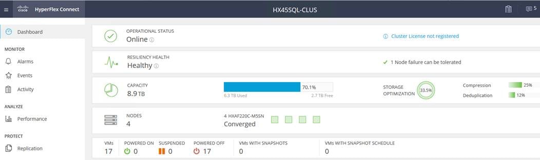
Make sure that the VMware ESXi Host service profiles in Cisco UCS Manager are all healthy without any errors. Figure 17 shows the service profile status summary from the Cisco UCS Manager UI.
Figure 17. Cisco UCS Manager Service Profile
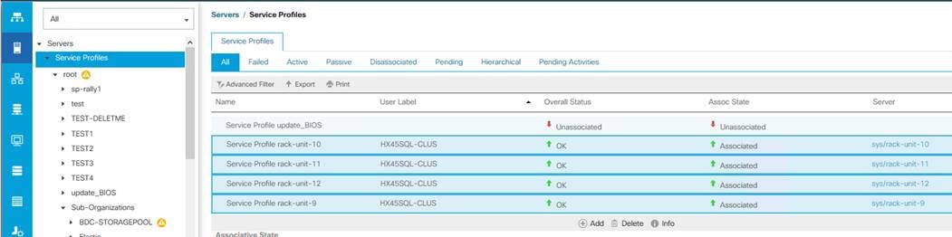
To deploy SQL Server virtual machine on Cisco HyperFlex system, follow these steps:
1. Create datastores for storing SQL Server guest virtual machines and make sure that the datastores are mounted on all the Cisco HyperFlex cluster nodes. The procedure for adding datastores to the Cisco HyperFlex system is provided in the Cisco HyperFlex Administration Guide. Figure 18 shows creation of a sample datastore. This example uses an 8-KB block size for the datastore, which is appropriate for the SQL Server database.
Figure 18. HyperFlex Datastore Creation
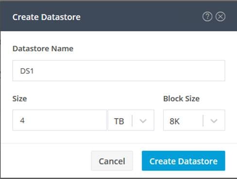
2. Create a virtual machine on the vCenter. Make sure that OS, data, and log files are segregated and balanced by configuring separate Paravirtual virtual SCSI controllers as shown in Figure 12. In VMware vCenter, go to Hosts and Clusters -> datacenter -> cluster -> VM-> VM properties -> Edit Settings to change the VM configuration as shown in Figure 19 and Figure 20.
Figure 19. Sample SQL Virtual Machine Disk Layout
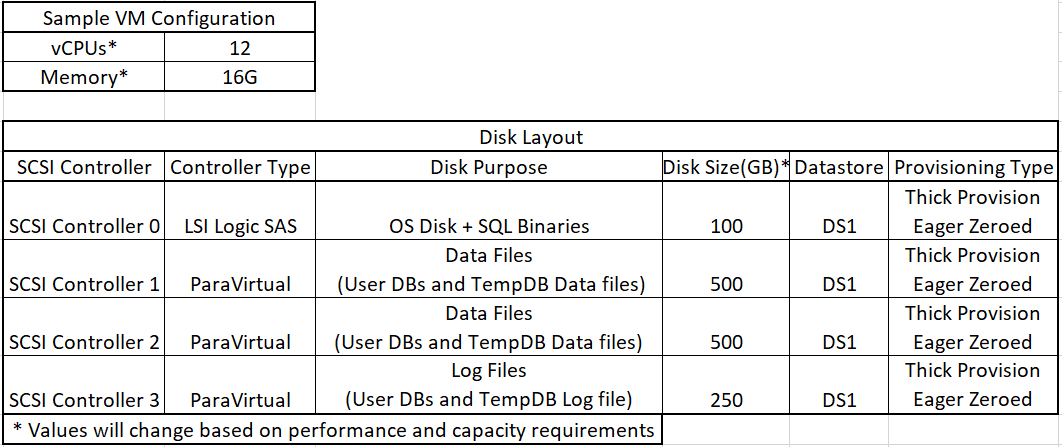
Figure 20. SQL VM Configuration
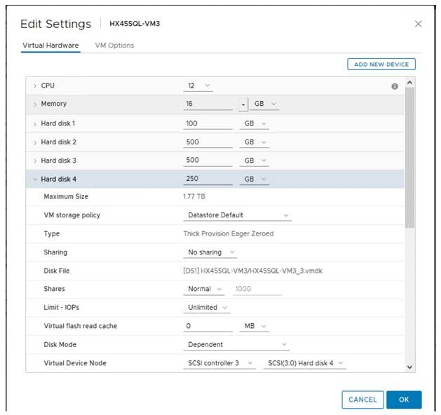
3. Edit Virtual Machine settings, Click on VM Options and set Firmware to BIOS for legacy boot. If not leave it at default value for EFI boot.
4. Mount Windows 2019 OS DVD to the Virtual Machine, Power On the Virtual Machine and install the Windows server 2019.
5. Optionally, add the Windows Guest to Active Directory domain.
6. Initialize, format, and label the volumes for Windows OS files, SQL server data and log files. Use 64K for the allocation unit size when formatting the volumes. Figure 21 (disk management utility of Windows OS) shows a sample logical volume layout of our test virtual machine.
Figure 21. Disk Layout within SQL Virtual Machine
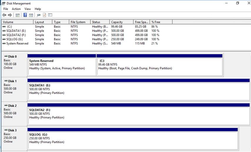
7. Increase PVSCSI adapter’s queue depth by adding a registry entry inside the guest VM as described in the VMware knowledgebase article: https://kb.vmware.com/s/article/2053145. Both RequestRingPages and MaxQueueDepth should be increased to 32 and 254 respectively. Since the queue depth setting is per SCSI controller, consider additional PVSCSI controllers to increase the total number of outstanding IOPS the VM can sustain.
8. When the Windows Guest Operating System is installed in the virtual machine, it is highly recommended to install VMware tools as explained here: https://kb.vmware.com/s/article/1014294
9. Set the Windows Guest power settings to “High Performance”.
10. Install Microsoft SQL Server 2019 on the Windows machine. To install the database engine on the guest VM, refer to this Microsoft document: https://docs.microsoft.com/en-us/sql/database-engine/install-windows/install-sql-server-from-the-installation-wizard-setup?view=sql-server-ver15.
a. Download and mount the required edition of Microsoft SQL Server 2019 ISO to virtual machine from the vCenter GUI. The choice of Standard or Enterprise edition of Microsoft SQL Server 2019 can be selected based on the application requirements.
b. On the Server Configuration window of SQL server installation, make sure that instant file initialization is enabled by enabling check box as shown in Figure 22. This enables the SQL server data files are instantly initialized avowing zeroing operations.
Figure 22. Enabling Instant File Initialization for SQL Server Service
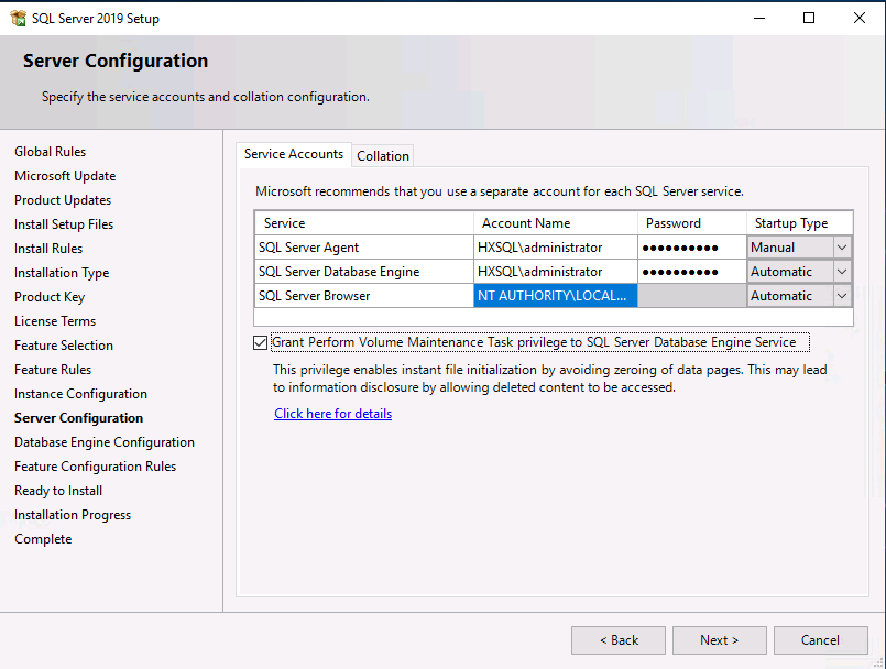
c. If the SQL server service account is not member of local administrator group, then add SQL server service account to the “Perform volume maintenance tasks” and “Lock pages in Memory” policies using Local Security Policy editor as shown in Figure 23. Open Local Group Policy Editor (run > gpedit.msc) and navigate to Computer Configuration > Windows Settings > Security Settings >Local Policies > User Right Assignment
Figure 23. Enabling Instant File Initialization for SQL Server Service
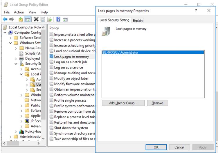
d. In the Database Engine Configuration window under the TempDB tab, make sure the number of TempDB data files are equal to 8 when the vCPUs of the SQL VM is less than or equal to 8. If the number of vCPUs is more than 8, start with 8 data files and try to add data files in the multiples of 4 when the contention is noticed on the TempDB resources (use SQL Dynamic Management Views). The following diagram shows that there are 8 TempDB files chosen for a SQL virtual machine which has 8 vCPUs. Also, as a best practice, keep the TempDB data and log files on two different volumes.
Figure 24. TempDB Configuration
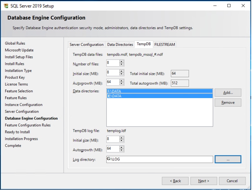
11. When the SQL server is successfully installed, use SQL server Configuration manager to verify that the SQL server service is up and running as shown in Figure 25.
Figure 25. SQL Server Configuration Manager
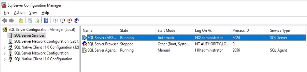
e. Create a user database using SQL Server Management studio or Transact-SQL so that the database logical file layout is in line with the desired volume layout. Detailed instructions are here: https://docs.microsoft.com/en-us/sql/relational-databases/databases/create-a-database
Microsoft SQL Server Deployment using HyperFlex iSCSI storage and Failover Cluster (FCI)
This section provides detailed steps and recommendations for configuring HyperFlex iSCSI network and deploying Microsoft SQL Server standalone and Failover Cluster (FCI) instances using HyperFlex iSCSI volumes.
HyperFlex iSCSI Configuration
To create HyperFlex iSCSI network, follow these steps:
![]() For more information refer to the “HX 4.5 iSCSI administration guide” here: https://www.cisco.com/c/en/us/td/docs/hyperconverged_systems/HyperFlex_HX_DataPlatformSoftware/AdminGuide/4-5/b-hxdp-admin-guide-4-5/m-hxdp-iscsi-manage.html
For more information refer to the “HX 4.5 iSCSI administration guide” here: https://www.cisco.com/c/en/us/td/docs/hyperconverged_systems/HyperFlex_HX_DataPlatformSoftware/AdminGuide/4-5/b-hxdp-admin-guide-4-5/m-hxdp-iscsi-manage.html
1. Log into the HyperFlex Connect dashboard and click on iSCSI tab. On the right hand pane, click Actions and then click Configure Network.
2. From the Configure iSCSI Network window (Figure 26), provide the following details:
a. Subnet: iSCSI network subnet
b. Gateway: Check the Gateway checkbox only when you are planning to deploy a routable iSCSI network (L3). You need to provide gateway IP address for iSCSI network. It is not recommended to add an extra L3 hop in the path of the iSCSI traffic.
c. IP Range: Provide range of IP for each ESXi node. This IP will be consumed by the HyperFlex controller VMs running on each ESXi node.
d. iSCSI Storage IP (iSCSI Cluster IP): Provide one IP address which will be endpoint for HyperFlex iSCSI network. This IP address will be the HyperFlex target iSCSI IP which iSCSI clients will connect to.
e. By default, MTU is set to 9000 and do not change it from default value.
f. iSCSI VLAN: If you are planning to use existing VLAN for iSCSI network, select the “Select an existing VLAN” option and provide the VLAN ID. If not, select “Create a new VLAN” option and provide VLAN ID, VLAN Name, UCS manager IP addresses and it credentials to create a new VLAN on the UCSM. In this case, make sure the required VLANs and interface configuration is implemented at the upstream switches also.
3. Once all the details are provided ,click OK to create the iSCSI network. The iSCSI network configuration can be verified by clicking the Activity tab.
The following screenshot shows a sample iSCSI network Configuration.
Figure 26. HyperFlex iSCSI Network Configuration
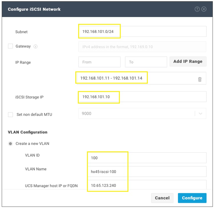
![]() Make note of these target IP addresses of HyperFlex nodes (192.168.101.11 to 14) as well as the Cluster IP Address CIP (192.168.101.10). These IP addresses will be used later for connecting to the iSCSI volumes within the Guest VMs.
Make note of these target IP addresses of HyperFlex nodes (192.168.101.11 to 14) as well as the Cluster IP Address CIP (192.168.101.10). These IP addresses will be used later for connecting to the iSCSI volumes within the Guest VMs.
4. When the iSCSI network is configured successfully, verify the following:
a. Ensure that iSCSI VLAN is created in the UCSM and ensure that iSCSI VLAN is tagged on storage-data-a and storage-data-b vNIC templates (in the UCSM, go to LAN >Polices > << Your HX Organization >> > vNIC Templates > VLANs)
b. In each ESXi node, ensure a new port group “Storage Controller iSCSI Primary” with iSCSI VLAN is created under “hx-storage-data” vswitch. And verify that HyperFlex controller VMs are connected to this iSCSI network.
c. Logon to any one of the HyperFlex controller VMs and ensure that you can reach all the iSCSI IP addresses and iSCSI CIP with jumbo frames as shown in Figure 27.
Figure 27. Verifying iSCSI Network Reachability with Jumbo Frames
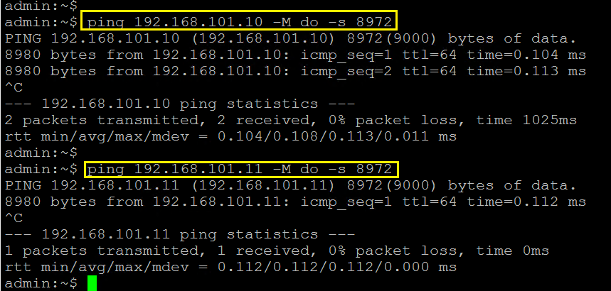
Configure iSCSI Network on SQL VMs and Gathering IQN
This section provides steps for configuring ISCSI network for SQL virtual machines. Before proceeding with below steps, create virtual machine by following the VM configuration best practices as detailed in the Deployment Procedure section. Once VMs are created, install Windows Server 2019 Guest Operating system, change the power settings, and add them to Active Directory Domain as explained in the previous sections.
![]() With the exception of the boot disk (Hard disk 1), do not add any VMDKs from NFS datastore. Later iSCSI volumes will be configured and used for storing SQL database files.
With the exception of the boot disk (Hard disk 1), do not add any VMDKs from NFS datastore. Later iSCSI volumes will be configured and used for storing SQL database files.
Configure iSCSI Network for SQL VMs
To expose SQL VMs to the HyperFlex iSCSI network, follow these steps:
1. Connect vCenter, select the SQL virtual machine and Shutdown.
2. Right-click the VM and select Edit Settings (Figure 28). Click Add New Device and select Network Adaptor.
3. Expand the newly added Network Adaptor and browse to select Storage Controller iSCSI Primary port group. Ensure to set the Adapter Type as VMXNET3 as shown in Figure 28.
4. Repeat steps 1-3 to add more than one iSCSI network adaptor to the SQL virtual machine.
Figure 28. Adding iSCSI Network to the SQL VMs
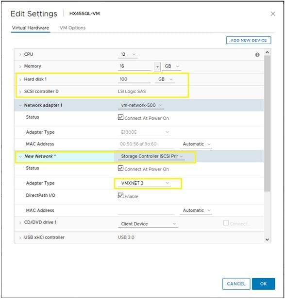
5. Open the iSCSI interface properties from Server manager > Local Server > Click the iSCSI Network interface and assign IP address (must be in the iSCSI network subnet) to the iSCSI adapter and change Jumbo Packet from 1514 to 9000 as shown in Figure 29. Optionally the network adapter can be renamed to “iSCSI” for easy identification. Repeat this step for each iSCSI adapter if the VM is configured with more than one iSCSI adapters.
Figure 29. Setting Jumbo Frames on iSCSI Adapter
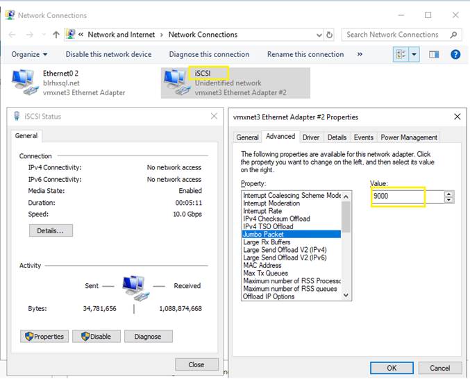
6. Verify that HyperFlex iSCSI CIP is reachable from the SQL VMs with jumbo frames (without fragmentation) from OS Command prompt using ping command. Ensure iSCSI VLAN is configured in the upstream switches for the use case where guest SQL VM is hosted outside the HX cluster.
7. To allow access to initiators outside of the iSCSI VLAN subnet, use the “hxcli iscsi allowlist” command. For example: hxcli iscsi allowlist add --ips 192.168.101.3. For more information, see the CLI Guide, 4.5.
Figure 30. Verifying Reachability of HyperFlex iSCSI CIP with Jumbo Frames

8. Make note of the IQN (iSCSI Qualified Name) of SQL client machines. These IQN will be used to create Initiator Groups discussed later in the below section. To find out the IQN of the Windows Server 2019 Client machine, follow these steps:
a. Open the Server Manager and click Tools and select Services. In the services Window, select Microsoft iSCSI Initiator Service and start the service.
b. Open the iSCSI initiator from Server Manager > Tools > iSCSI Initiator.
c. On the iSCSI Initiator Properties window, click the Configuration tab. Make a note of the Initiator Name as shown in Figure 31.
Figure 31. Gathering iSCSI Initiator Name from Windows Machine
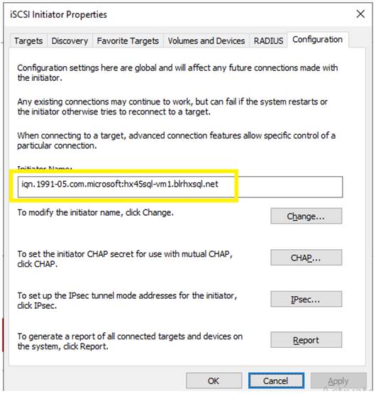
Configure iSCSI Initiator Groups, iSCSI Targets, and LUNs
iSCSI initiator Group is group of one or more IQNs (iSCSI Qualified Names) of client machines. To create an Initiator Group, follow these steps:
1. On the HyperFlex Connect Dashboard (Figure 32), click iSCSI and then click Initiator Groups. Enter the name “SQL-VMs-GRP” and enter the IQN gathered in the previous step and click Add Initiators. For Microsoft SQL failover Cluster Instance (FCI), IQNs of all the members of windows Server Failover cluster must be added. The following screenshot shows creating Initiator Group with two IQNs used for deploying Windows failover Cluster (WSFC). For a standalone SQL VM deployment, enter the IQN of the single VM.
Figure 32. Creating Initiator Group
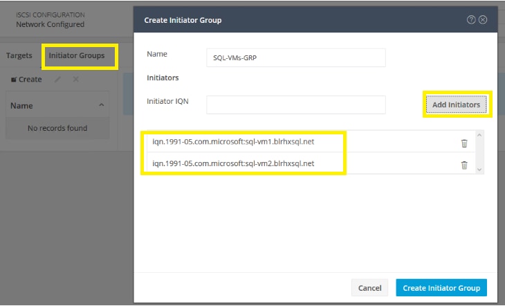
2. Create a target by clicking Targets and enter the Target name “SQL-FCI-CLUS”. To use CHAP Authentication, select the Enable CHAP Authentication check box and provide username and a secret.
3. Click the Target “SQL-FCI-CLUS” created in the previous step and then click Create LUN to create iSCSI volumes under the target. Enter Volume name and size and click OK.
4. Repeat step 3 to create more than one iSCSI volume. The following figure shows different volumes are created for storing SQL FCI database data and log files and a Quorum disk for storing Microsoft Cluster configuration.
Figure 33. iSCSI Volumes
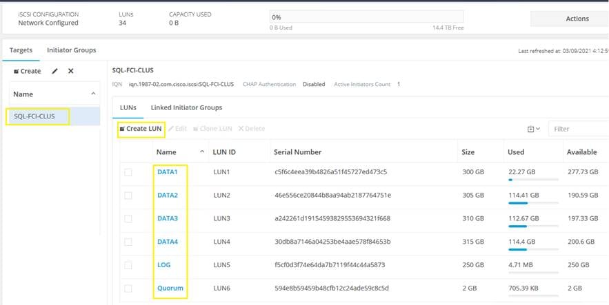
5. Map these iSCSI volumes to the Initiator group which was created in the previous step by clicking Linked Initiator Groups and then click Link and check the box as shown in Figure 34.
Figure 34. Mapping iSCSI Volumes
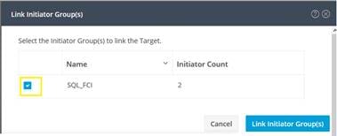
Discover and Connect HyperFlex Target within the SQL VMs
This section provides the steps for connecting HyperFlex Target, installing and configuring MPIO with in the Guest VM.
To connect to the HyperFlex iSCSI target, follow these steps:
1. Log into the SQL VMs with administrator account and open the iSCSI initiator.
2. Click the Discovery tab and click Discover Portal.
3. If the VM has single iSCSI adapter, enter the HyperFlex iSCSI Cluster IP (CIP) and click Advanced. Select Microsoft ISCSI initiator for the local adapter and select the SQL VM’s ISCSI IP address for Initiator IP as shown in Figure 35. Refer to the Appendix for PowerShell scripts for configuring the iSCSI configuration with single iSCSI adapter.
Figure 35. Discovering to HyperFlex Target
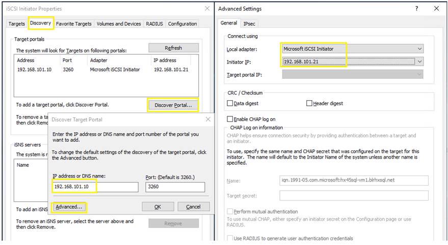
4. If the VM is configured with multiple iSCSI adapters (initiators), it is recommended to connect each initiator directly to a target iSCSI ip address of different HyperFlex nodes. For instance, if the VM is configured with two iSCSI IP adapters with IP addresses 192.168.101.21 and 192.168.101.22 respectively, then connect 192.168.101.21 to 192.168.101.11 and 192.168.101.22 to 192.168.101.12. Refer the Appendix section for PowerShell scripts for configuring the iSCSI configuration with multiple iSCSI adapters.
5. Connect to the discovered iSCSI target devices by clicking Connect in the Targets tab. In the Connect to Target window, check the Enable Multipath box, and click Advanced. On the Advanced Settings, select Microsoft iSCSI Initiator for the local adapter, SQL VMs IP address as Initiator IP and select HyperFlex iSCSI CIP or HyperFlex node target iSCSI IP for Target Portal IP.
Figure 36. Connecting to HyperFlex Target
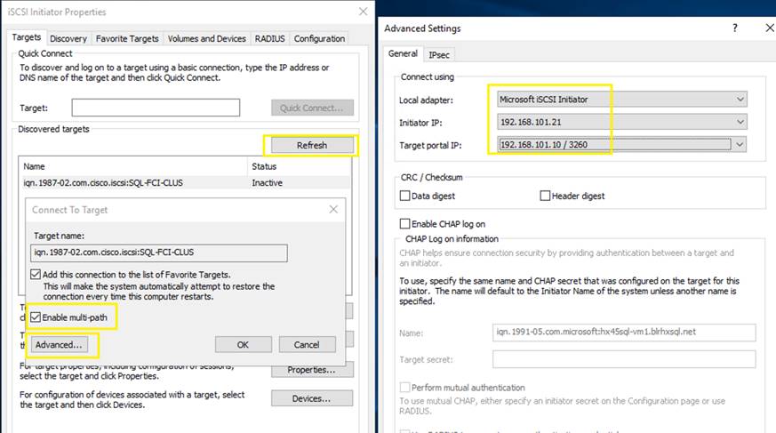
6. Repeat step 5 for each initiator iSCSI IP address to connect to the corresponding HyperFlex target IP address.
Install and Configure MPIO
To install Windows native multipath drivers, follow these steps:
1. Log into the SQL VMs with administrator account. Run the following PowerShell command to install Windows MPIO and Failover Clustering features. Restart the VMs once these features are installed and then verify if the features are installed successfully. Note that Failover Clustering feature is only required when deploying Windows Failover Cluster.
Figure 37. Installing Windows Features – MPIO and Failover Clustering
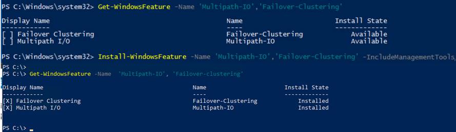
![]() Installing and configuring MPIO is not required when the VM is configured with single iSCSI adapter. It is applicable only when the VM is configured with more than one iSCSI adapter.
Installing and configuring MPIO is not required when the VM is configured with single iSCSI adapter. It is applicable only when the VM is configured with more than one iSCSI adapter.
2. Open the MPIO tool from Windows Server manager > Tools > MPIO and click the Discover Multi-Paths tab and check the Add support for iSCSI devices box and click Add. Under Others section, select HyperFlex iSCSI Target device ID (HYPRFLEXHX.VolumeStorage) and click Add. Restart the SQL VM.
Figure 38. Configuring MPIO
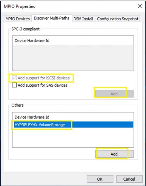
3. Initialize, partition, and format the iSCSI volumes with NTFS file system with 64KB allocation unit size. Open the Disk Management tool verify the MPIO settings as shown Figure 39. Ensure to use Round Robin for MPIO policy. Based on the number of iSCSI adapters and connections, you may see more than one path. The following figure shows multiple paths where the guest VM is configured with two iSCSI adapters.
Figure 39. iSCSI Volumes in Disk Management Tool
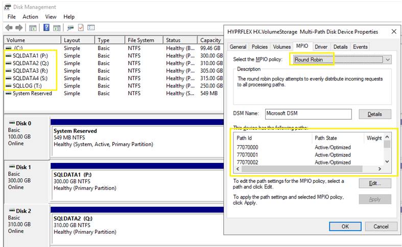
Refer to the Appendix for detailed steps for configuring Guest for iSCSi access for both single and multiple initiators use cases.
At this point, the VMs are configured with iSCSI volumes to be used for storing database files. These VMs can be used to deploy standalone SQL Server instance or Failover Cluster instance (FCI).
To deploy the standalone SQL Server using iSCSI volumes, go to: https://docs.microsoft.com/en-us/sql/database-engine/install-windows/install-sql-server-from-the-installation-wizard-setup?view=sql-server-ver15
To deploy the SQL Server Failover Cluster instance using iSCSI volumes, follow the steps in the next section.
Deploy Windows Server Failover Cluster (WSFC) using iSCSI Volumes
SQL Server Failover Cluster (FCI) leverage underlying Microsoft Windows Server Failover Cluster (WSFC). Hence before FCI deployment, we need to deploy WSFC on the Virtual Machines. For more information about the Windows Failover Cluster deployment go to: https://docs.microsoft.com/en-us/windows-server/failover-clustering/failover-clustering-overview
This section provides the steps for deploying two node Windows Server Failover Cluster using HyperFlex iSCSI volumes. HyperFlex iSCSI volumes provide the required shared storage for the Windows failover cluster.
To install Windows Failover Cluster, follow these steps:
1. Before proceeding with Failover Cluster installation, ensure all the prerequisites are met as explained here: https://docs.microsoft.com/en-us/windows-server/failover-clustering/clustering-requirements
2. If the Windows Failover Cluster feature is not installed on the VMs, install the feature as explained in the previous section.
3. Open the Failover Cluster Manager (RUN > cluadmin.msc) and click Validate Cluster.
4. In the Validate a Configuration Wizard, click Browse and select your Active Directory Domain and enter the server names as shown in Figure 40. Click Next once all the required servers are listed.
Figure 40. Validation of Cluster Configuration
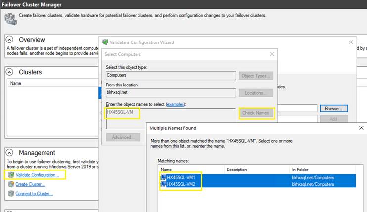
5. Select the list of tests to be validated by the Cluster validation. Under storage, uncheck Validate Storage Spaces Persistent Reservation test and uncheck Storage Spaces Direct option. Click Next.
Figure 41. Validation Tests
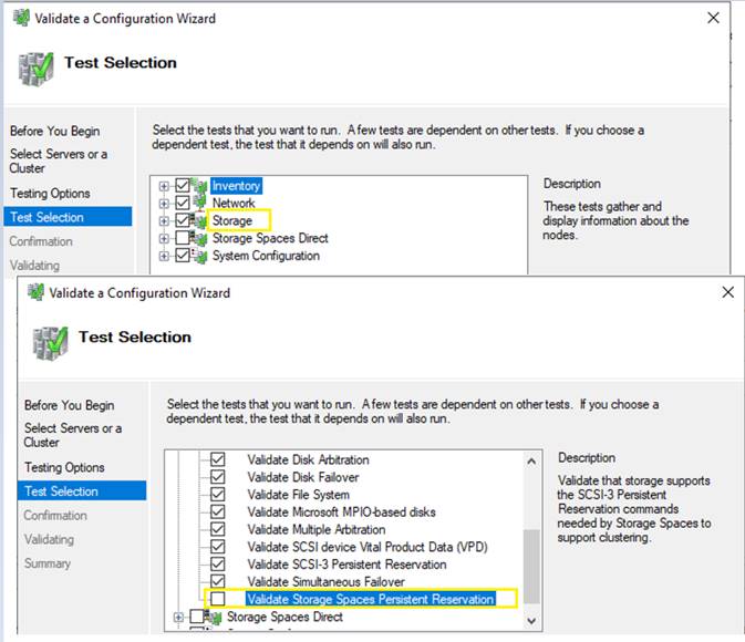
6. When the validation is completed, review the validation report, and ensure no errors are reported by the Cluster validation tool. If any errors are reported, fix the errors, and rerun the validation test again until no errors are reported. Warning messages can be ignored.
7. When no errors are reported by the Cluster validation, a failover cluster can be created. To create cluster, click Create and select the same servers as earlier and click Next.
8. Enter a name for Cluster Name and select management network and provide IP address for the cluster as shown in Figure 42 and then click Next to complete the cluster creation.
Figure 42. Cluster name and IP Address
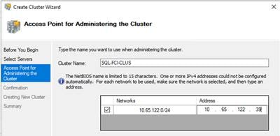
9. Connect to the newly created Windows Cluster by providing the name of the cluster. Expand the cluster and click the Networks tab. Select iSCSI network and select Do not allow cluster network communication on this network option as shown in Figure 43. Optionally, you can rename the cluster from “Cluster Network 2” to “iSCSI”.
Figure 43. Configuring iSCSI Network
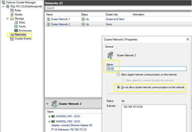
10. Expand the Storage tab and right-click Disks and select Add Disk. Select the all the iSCSI disks and click Add. Optionally, you can rename the Clustered disks to some meaning full names (such as SQLDATA1, SQLLOG, Quorum and so on) as shown in Figure 44.
Figure 44. Adding iSCSI Volumes to Cluster
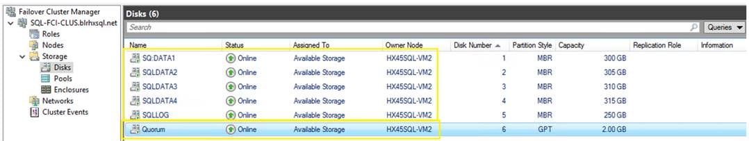
11. Configure the Quorum disk to avoid split-brain scenarios. There are different ways to configure the Quorum disk based on number of server nodes and type of storage in use. For this two-node Windows Server Failover Cluster, a dedicated 2GB iSCSI volume is created in HyperFlex and is used for storing the Quorum disk configuration. To configure the iSCSI disk as Quorum witness, follow these steps:
a. Connect to the Windows Failover Cluster and right-click it, select More Actions, and select Configure Cluster Quorum Settings. Click Next.
b. Select Advanced Quorum configuration and click Next.
c. Select All Nodes and click Next. Select the Configure a Disk witness option and click Next.
d. Select the 2GB Quorum disk as shown in Figure 45,click Next, and complete the Quorum configuration.
Figure 45. Quorum Disk Configuration
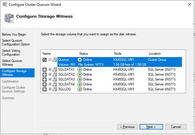
Now the Windows Failover Cluster is ready and clustered applications such as SQL Server Failover Cluster (FCI) can now be added to the cluster.
Deploy Microsoft SQL Server Failover Cluster Instance (FCI)
This section provides the steps for deploying two node SQL Server Failover Cluster Instance (FCI). Failover Cluster Instances leverages Windows Server Failover Clustering (WSFC) functionality to provide local high availability through redundancy at the server-instance level-a failover cluster instance (FCI). An FCI is a single instance of SQL Server that is installed across Windows Server Failover Clustering (WSFC) nodes. On the network, an FCI appears to be an instance of SQL Server running on a single computer, but the FCI provides failover from one WSFC node to another if the current node becomes unavailable. For more details on Failover Cluster, refer to: https://docs.microsoft.com/en-us/sql/sql-server/failover-clusters/windows/always-on-failover-cluster-instances-sql-server?view=sql-server-ver15#Overview
To create FCI, follow these steps:
1. Download and copy the latest SQL Server 2019 ISO image to windows server nodes. Mount the ISO on each node. For SQL Server FCI deployment. one node needs to be treated as active node and the remaining nodes to be treated as passive nodes. Install clustered SQL Server Instance on Active node first and then join the remaining passive nodes to the clustered instance.
2. On the Active node, from SQL Server 2019 installation media, execute setup.exe to launch the SQL Server Installation center. Click the Installation link and click New SQL Server failover cluster installation.
3. In the Install Failover Cluster Rules window, ensure all the rules are passed without any errors. If any errors reported, fix them, and rerun the rules.
Figure 46. Failover Cluster Rules
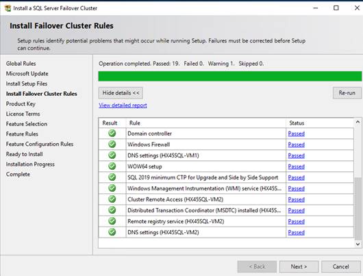
4. In the Product Key dialog box, enter the license key. If you don’t have a license key, select Evaluation edition, and click Next.
5. In the License Terms window, review the privacy statement and accept the license terms. Click Next.
6. In the Feature Selection window, select Database Engine Services, Client Tools Connectivity, Client Tools SDK, Client tools Backward Compatibility and so on and click Next.
7. In the Instance Configuration window, provide a name to the SQL FCI instance and select Default instance if you would like to install the default instance. If not, provide a name to the SQL instance (SQL Named Instance). Click Next.
8. In the Cluster Resource Group dialog box, check the resources available on your WSFC. This informs you that a new Resource Group will be created on your WSFC for the SQL Server FCI. To specify the SQL Server cluster resource group name, you can use the drop-down list to specify an existing group to use or type the name of a new group to create it. Accept all the defaults and click Next.
9. In the Cluster Disk Selection dialog box, select the available disk groups that are on the WSFC for the SQL Server FCI to use. Click Next. The list of disks displayed in this dialog box will depend on how you configured shared disk resources in your WSFC.
Figure 47. Selecting Cluster Disks for FCI
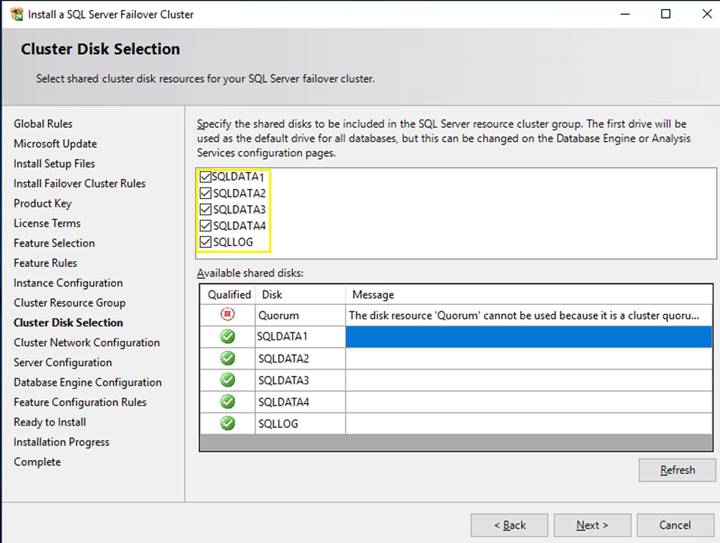
10. In the Cluster Network Configuration dialog box, enter the IP address and subnet mask values that your SQL Server FCI will use. Select the IPv4 checkbox under the IP Type column as you will be using a static IP address. The SQL Server Network Name with this virtual IP address will be created as an entry in your DNS server.
Figure 48. SQL FCI Virtual IP Address
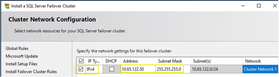
11. In the Server Configuration Window, provide the credentials for the SQL Server service accounts in the Service Accounts tab. Make sure that both the SQL Server Agent and SQL Server Database Engine services Startup Type is Manual. The WSFC will take care of stopping and starting these services. Select the checkbox Grant Perform Volume Maintenance Task privilege to SQL Server Database Engine Service. This enables Instant File Initialization for SQL Server.
Figure 49. SQL Service Startup Account and Instant File Initialization
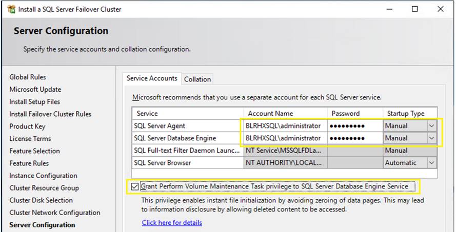
12. In the Database Engine Configuration Window under the Server Configuration tab, select Windows authentication mode or Mixed mode in the Authentication Mode section. If required, you can change it later after the installation is complete. Add the currently logged on user to be a part of the SQL Server administrators group by clicking Add Current User in the Specify SQL Server Administrators section. You can also add Active Directory domain accounts or security groups as necessary. In the Data Directories tab, specify the location of the data files, the log files, and the backup files. In the TempDB tab, you can set the number of tempdb data files, initial size and auto growth settings of both data and log files as well as their corresponding locations as shown Figure 50. Optionally, you can also store tempdb database files on a local disk in a WSFC. Should you decide to store tempdb on a local disk, you will get prompted to make sure that all the nodes in the WSFC contain the same directory structure and that the SQL Server service account have read/write permissions on those folders. In the MaxDOP tab, change the Maximum Degree Parallelism option to the desired value. For more details on MAXDOP, click this link. In the Memory tab, you can change the minimum and maximum memory allocations. These settings can also be changed later after the SQL Server FCI installation. Click Next when all the tabs are configured correctly and complete the installation.
Figure 50. SQL FCI TempDB Configuration
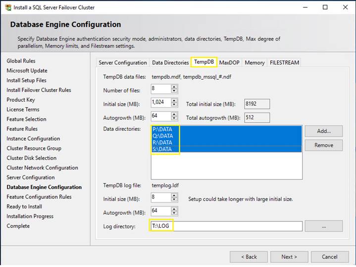
13. In the Ready to Install window, verify all the settings once and click Next to start the SQL FCI installation. Once installation completes close the wizard. With this SQL FCI installation completes on the Active node.
Figure 51. SQL FCI Installation Completion
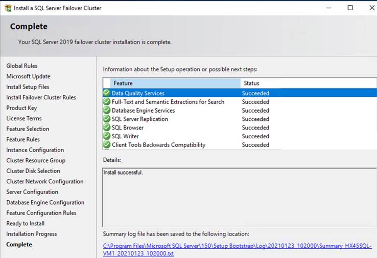
14. At the completion of a successful installation and configuration of the node, you now have a fully functional SQL Server 2019 FCI. To validate, open the Failover Cluster Manager console (RUN > cluamin.msc) and click SQL Server under Roles. Make sure that all dependencies are online as shown in Figure 52.
Figure 52. SQL FCI In Cluster
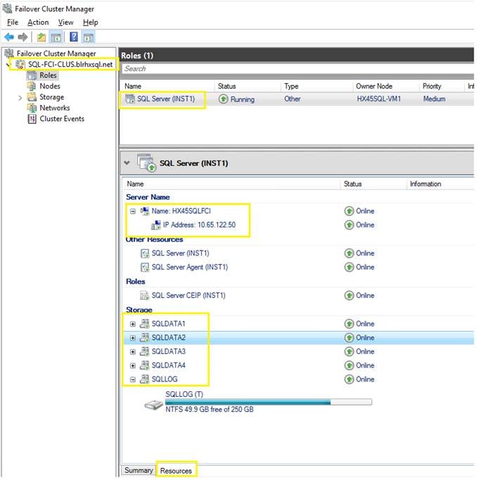
15. Although you have a fully functioning SQL Server 2019 FCI, it is not highly available yet because the SQL Server binaries are only installed on one of the nodes in the WSFC. To make it highly available, you have to add the second node of the WSFC to the SQL Server FCI. To add other node(s) to an existing SQL Server 2019 FCI, follow these steps:
a. Log into the node (passive) with administrator account and execute setup.exe file from SQL 2019 installation media to launch SQL Server Installation Center. Click Install.
b. Click the Add node to a SQL Server failover cluster link. This will run the SQL Server 2019 Setup wizard.
c. In the Product Key window enter the product key that came with your installation media or select Evaluation edition and click Next.
d. In the License Terms window, review the privacy statement and accept the license terms. Click Next.
e. In the Add Node Rules dialog box, validate that the checks return successful results. If the checks returned a few warnings, make sure you fix them before proceeding with the installation.
f. In the Cluster Node Configuration dialog box, validate that the information for the existing SQL Server 2019 FCI that you installed. Click Next
g. In the Cluster Network Configuration window, validate that the IP address information is the same as the one you provided earlier. Click Next.
h. In the Service Accounts window, verify that the information is the same as what was used to configure the first node. Provide the appropriate credentials for the corresponding SQL Server service accounts. Select the Grant Perform Volume Maintenance Task privilege to SQL Server Database Engine Service checkbox to enable Instant File Initialization for SQL Server.
i. In the Feature Rules window, verify that all checks are successful. Click Next.
j. In the Ready to Add Node window, verify that all configuration settings are correct. Click Install to proceed with the installation.
k. To add additional nodes (subject to max number of nodes in a SQL FCI Failover Cluster supported by ESXi) to the SQL Server 2019 FCI, repeat steps a to j. For more information on SQL FCI max limits on VMware ESXi, refer to: https://kb.vmware.com/s/article/2147661
l. Try Connecting SQL FCI using SQL Management studio or SQLCMD tool. For the Default instance, use: “virtual Name”. For the named SQL FCI, use “virtual Name \instance name.”
m. Create a user database using SQL Server Management studio or Transact-SQL so that the database logical file layout is in line with the desired volume layout. Detailed instructions are here: https://docs.microsoft.com/en-us/sql/relational-databases/databases/create-a-database
n. Perform some failure tests and verify if SQL FCI is failing over to other node automatically.
16. Finally, a VMWare DRS anti-affinity rules must be configured to ensure that each SQL host of the Windows failover cluster must be running on different VMware ESXi hosts in order to avoid a situation where all the guest VMs going down when the underlying ESXi host unavailable for any reason. For more details on configuring VMware anti-affinity rules, see: https://docs.vmware.com/en/VMware-vSphere/6.0/com.vmware.vsphere.resmgmt.doc/GUID-7297C302-378F-4AF2-9BD6-6EDB1E0A850A.html
Clone iSCSI Volumes
HyperFlex iSCSI volumes allows to clone the volumes which can be either Crash consistent or Application consistent. To take application consistent clones of the iSCSI volumes, an Operating System agent for Windows Sever 2016 or later is available from HyperFlex and this agent must be installed on the Windows Guest VM prior to taking application consistent clones. This agent will coordinate the required pausing and quiescing activity with underlying HyperFlex Cluster. The cloned volume is created in its own target and after the cloning is completed, the new target must be linked to with an initiator Group so that the client can gain access to the newly created iSCSI volumes.
For detailed steps for cloning iSCSI volumes refer to: https://www.cisco.com/c/en/us/td/docs/hyperconverged_systems/HyperFlex_HX_DataPlatformSoftware/AdminGuide/4-5/b-hxdp-admin-guide-4-5/m-hxdp-iscsi-manage.html#Cisco_Task.dita_f2a03707-a584-4938-aad6-92788bd9d43d
Solution Resiliency Testing and Validation
This section details some of the failure tests conducted to validate the robustness of the solution from for NFS and iSCSI protocols. These tests were conducted on a HyperFlex cluster built with four HXAF220c-M5N All-NVMe nodes. Table 3 lists the component details of the test setup.
Table 3. Hardware and Software Components Details used in HyperFlex All-NVMe Testing and Validation
| Component |
Details |
| Cisco HyperFlex HX data platform |
Cisco HyperFlex HX Data Platform software version 4.5.1a-39020 Replication Factor: 3 Inline data dedupe/ compression: Enabled(default) |
| Fabric Interconnects |
2x Cisco UCS 3rd Gen UCS 6332-16UP Cisco UCS Manager Firmware: 4.1(2b) |
| Servers |
4x Cisco HyperFlex HXAF220c-M5N All-NVMe Nodes |
| Processors Per Node |
2x Intel® Xeon® Gold 6240 CPUs @2.60GHz, 18 Cores each 768GB (24x 32GB) at 2933 MHz |
| Cache Drives Per Node |
1x 375G Intel Optane NVMe Extreme Perf SSD |
| Capacity Drives Per Node |
8x 1TB Intel P4500 NVMe High Perf. Value Endurance |
| Hypervisor |
VMware ESXi 6.7U3-17167734 |
| Network Switches |
2x Cisco Nexus 9396PX (9000 series) |
| Guest OS |
Windows 2019 Standard Edition |
| Database |
Microsoft SQL Server 2019 |
| Database Workload |
Online Transaction Processing With 70:30 Read Write Mix and Decision Making System (DSS) workload with 90:10 |
Some of the major failure tests conducted (using iSCSI volumes) on the setup include:
● Node failure tests
● Failure tests for SQL Failover Cluster Instance
For all these tests, HammerDB testing tool was used to generate the required stress on the guest SQL Server virtual machines deployed on the HyperFlex All-NVMe cluster. A separate client machine located outside the Cisco HyperFlex cluster was used to run the multiple instances HammerDB tool and generate the database workload on multiple SQL VMs.
Node Failure Test for iSCSI
The intention of this failure test is to analyze how the HyperFlex behaves when failure is introduced into the cluster on an active node (running multiple guest VMs with iSCSI volumes). The expectation is that the Cisco HyperFlex system should be able to detect the failure, initiate automatic VM migration from a failed node to the one of the surviving nodes and retain the pre-failure state with an acceptable limit of performance degradation.
In our testing, node failure was introduced when the cluster is stressed with eight SQL VMs (two VMs per host) and 40 iSCSI volumes (5 volumes per VM) utilizing 65-70% of cluster IO capacity and 40% of cluster CPU utilization. When one node was powered off (unplug both power cables), SQL guest VMs running on the failed node successfully failed over to one of the surviving nodes. After SQL VMs migrated to the surviving node, database consistency checks were run on the database and there were no database consistency errors were reported. Later, database workload was manually restarted on the VM. The impact observed on the overall performance (IOPS dip) because of failed node was around 20-25% which is due to the absence of one node. Later when the failed node was powered up, it rejoined the cluster automatically and started syncing up with the cluster. The cluster returned to the pre-failure performance within 5-10 minutes after the failed node was brought online (including the cluster sync-up time).
SQL Server Failover Cluster Instance (FCI) Failure Tests
Several hardware and software failure tests, including ESXi host failure, iSCSI path failures, VM failures and SQL failures, have been conducted to check the behavior of Failover Cluster Instance upon the failures. In all the test cases, a database consistency check was executed after the database recovered from the failure. In all the failure scenarios, database moved to the passive node (automatically or manually based on the failure type) and no data consistency errors were reported in the error logs and DBCC commands.
Several database performance tests were conducted on the solution to demonstrate the HyperFlex capabilities for both NFS and iSCSI volumes. This section discusses few major tests and their results conducted for SQL Server databases stored on NFS and iSCSI volumes.
The Cisco HyperFlex HX Data Platform uses a distributed architecture. A main advantage of this approach is that the cluster resources form a single, seamless pool of storage capacity and performance resources. This approach allows any individual virtual machine to take advantage of the overall cluster resources; the virtual machine is not limited to the resources on the local node that hosts it. This unique capability is a significant architectural differentiator that the HX Data Platform provides.
Several common data center deployment scenarios in particular benefit from the HX Data Platform:
● Virtual machine hotspot: Rarely do all the virtual machines in a shared virtual infrastructure uniformly utilize the resources. Capacity requirements for individual virtual machines usually differ, and their performance requirements are different at different points in time. With the Cisco HyperFlex distributed architecture, the infrastructure easily absorbs these hotspots, without causing capacity or performance hotspots in the infrastructure.
● Large virtual machine with large working set: Because the cluster presents a common pool of resources, organizations can deploy large applications and virtual machines with performance and capacity requirements that exceed the capability of any single node in the cluster.
Large SQL VM Test with NFS Volumes
A performance test was conducted with a large SQL Server virtual machine configured with VMDKs from HyperFlex NFS datastore. The cluster setup used for this test is the same setup as detailed in Table 3. Table 4 provides the details of the virtual machine configuration and workload used for this test. An OLTP workload with a 70:30 read-write ratio was exerted on the guest virtual machine. The workload stressed the virtual machine with CPU utilization of up to 65-70 percent, which resulted in 40% of ESXi host CPU utilization.
Table 4. SQL VM Configuration Details for Large VM Test
| Configuration |
Details |
| VM |
One VM test. The VM configured with 12 vCPUs, 16G Memory (14G to SQL) Four 300G Data volumes and one 250G Log volume: - First pair of data VMDKs attached to SCSI Controller 1 - Second pair of data VMDKs attached to SCSI Controller 2 - log VMDK attached SCSI Controller 3 |
| Workload |
Tool Kit: OLTP workload simulated with HammerDB testing tool Users: 90 Data Warehouses: 8000 DB Size= 800GB RW Ratio: 70:30 |
Figure 53 shows the performance of the single VM running a large SQL workload for about 3 hours.
Figure 53. Large Working Set SQLVM (with NFS volumes) Test
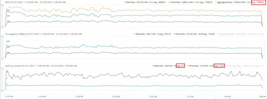
This test demonstrates the ability that HyperFlex has leveraged the resources from all nodes in the cluster to satisfy the performance (and capacity) needs of any given VM.
Some key points are as follows:
● Large VM with a very large working set size can get sustained high IOPS (and potentially higher IOPS with additional resources allocated to the VM) leveraging resources (capacity and performance) from all 4 nodes in the cluster.
● Dedupe and Compression is turned on by default.
● Delivers sustained IOPS for the entire test duration.
Multi VM High Performance Demanding SQL Workloads using NFS Volumes
This section demonstrates the HyperFlex All-NVMe cluster performance delivered when high storage performance demanding SQL workloads deployed across the cluster. For this test, eight medium sized SQL virtual machines (two VMs per node) were stressed to drive higher IOPS. The cluster setup used for this test is the same setup as detailed in Table 3. The details of the VM configuration and workload are listed in Table 5. OLTP workload with 70:30 read write ratio was exerted on each guest VM.
Table 5. VM Configuration and Workload Details for Multi VM High Performance Test using NFS Volumes
| Configuration |
Details |
| VM |
8 VM test each VM configured with 8 vCPUs, 16G Memory (14G to SQL) Four 300G Data volumes and one 250G Log volume: - First pair of data VMDKs attached to SCSI Controller 1 - Second pair of data VMDKs attached to SCSI Controller 2 & log VMDK attached SCSI Controller 3 |
| Workload |
Tool Kit & Workload: OLTP workload simulated with HammerDB testing tool Users: 25 Data Warehouses: 8000 DB Size= 800GB RW Ratio: 70:30 |
Figure 54 shows the performance driven by eight SQL virtual machines (Two VMs per node) driving high IOPS from each ESXi node. The test was executed for three hours. The following figure shows steady state window of the test.
Figure 54. Multi VM High Performance Test with 8 VMs (using NFS Volumes)
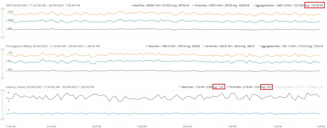
The test described above, demonstrates low latency and consistent performance delivered by a four node HyperFlex All-NVMe cluster as demanded by SQL virtual machines for a specific database workload simulated by HammerDB tool on each of the VMs. The cluster delivered nearly 130K IOPS under less than 5ms write latency. The workload stressed the virtual machine with CPU utilization of up to 65-70 percent, which resulted in 60% of ESXi host CPU utilization. Additional converged nodes (up to thirty two) can be added to scale IOPS while maintaining IO latencies within reasonable limits.
SQL Server Failover Instance (FCI) Performance Testing
The intention of this test is to demonstrate the performance delivered for SQL Server Failover Cluster Instance (FCI) hosted with in the HyperFlex All-NVMe cluster using shared HX iSCSI volumes.
A two-node Windows Server 2019 Failover Cluster was deployed with two guest VMs using HyperFlex iSCSI volumes as detailed in the previous sections. A SQL Server FCI deployed on top of the Windows Failover Cluster. The same All-NVMe cluster setup as detailed in Table 3 was used for this testing. Table 6 provides SQL Virtual Machine configuration and workload details used for this testing. For this test, an 800G database used and OLTP workload with 70:30 read write ratio was exerted on the FCI.
Table 6. VM Configuration and Workload details used for SQL SERVR Failover Cluster Instance (FCI) Testing
| Configuration |
Details |
| VM |
Single VM test. VM Configured with 12 vCPUs, 16G Memory (14G to SQL) Four 300G iSCSI volumes for Data files and one 250G iSCSI volume for Log file |
| Workload |
Tool Kit & Workload: OLTP workload simulated with HammerDB testing tool SQL Instance: SQL Server Failover Cluster Instance deployed on two-node Windows Failover Cluster Users: 60 Data Warehouses: 8000 DB Size= 800GB RW Ratio: 70:30 |
Figure 55 shows the performance driven by single Failover Cluster Instance deployed on a two-node Windows Failover Cluster. The test was executed for three hours.
Figure 55. SQL Server FCI Performance Test using iSCSI Volumes
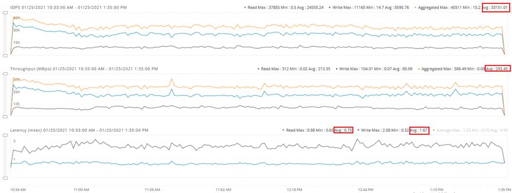
The test described above, demonstrates low latency and consistent performance delivered for a single Failover Cluster Instance. The cluster delivered nearly 33K under less than 2ms write latency and less than 1ms read latency. The workload stressed the guest VM with up to 45-50% of CPU utilization which resulted in ~39% of ESXi host CPU utilization. Higher IOPS can be achieved by adding more resources allocated to the VM and by pushing more user load from the test tool
Multi VM Test using iSCSI Volumes
This section demonstrates the HyperFlex All-NVMe cluster performance delivered when multiple Standard SQL Server VMs configured with iSCSI volumes deployed across 4-node HyperFlex All-NVMe cluster. For this test, eight SQL virtual machines (two VMs per node) were used. The same All-NVMe HyperFlex cluster as detailed in Table 3 was for running this test. The details of the VM configuration and workload are list in Table 7. OLTP workload with 70:30 read write ratio was exerted on each guest VM.
Table 7. VM Configuration and Workload Details used for Multi VM Test using iSCSI Volumes
| Configuration |
Details |
| VM |
8 VM test each VM is configured with: 6 vCPUs, 16G Memory (14G to SQL) Four 300G iSCSI volumes for Data files and one 250G iSCSI volume for Log volume |
| Workload |
Tool Kit & Workload: OLTP workload simulated with HammerDB testing tool Users: 25 Data Warehouses: 8000 DB Size= 800GB RW Ratio: 70:30 |
Figure 56 shows the performance driven by eight SQL virtual machines configured with iSCSI volumes spread across 4-node HyperFlex cluster. The test was executed for three hours and steady state duration.
Figure 56. Multi VM Test Using iSCSI Volumes
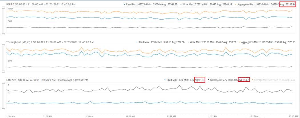
The test described above, demonstrates low latency and consistent performance delivered by a four node HyperFlex All-NVMe cluster as demanded by eight SQL virtual machines configured with iSCSI volumes. The cluster delivered nearly 86K under less than 5ms write latency. The workload stressed the virtual machine with CPU utilization of up to 35-40 percent, which resulted in 45-50% of ESXi host CPU utilization.
Decision Support System (DSS) or Datawarehouse (DW) Performance Testing with iSCSI Volumes
This section demonstrates HyperFlex All-NVMe cluster performance delivered for DSS workload using HyperFlex iSCSI volumes. Data warehouses are the aggregation of tiers of business data used to run analytics, report queries, plan strategies, improve processes, and support decisions. These systems typically involve reading large amounts of data from the storage system into the memory and crunch the data to provide meaning full insights into the data. There by these systems involve large sequential reads, also requires dense compute and memory capacities for parallel data processing.
An internal test tool was used to simulate DSS workload on 1000GB scale factor database. A standalone SQL Server VM was created and stored 1000G database data and log files on HyperFlex iSCSI volumes. The same All-NVMe HyperFlex cluster (detailed in Table 3) was for running this test. The details of the VM configuration and workload are list in Table 8. Using the internal tool kit, DSS workload with 90:10 read write ratio was exerted on the SQL VM .
Table 8. VM Configuration and Workload details used DSS test
| Configuration |
Details |
| VM |
1 VM is configured with: 24 vCPUs, 256G Memory Two 1.5TB iSCSI volumes for data file volumes and one 250G iSCSI volume for Log file. |
| Workload |
Tool Kit & Workload: Internal toolkit used to simulate DSS like workload Users: 9 parallel user connections each running 22 queries serially. DB Size: 1000GB RW Ratio: 90:10 |
Figure 57 shows the read and write bandwidth driven by the single SQL VM running DSS workload.
Figure 57. Total Read and Write Bandwidth of Single SQL VM Running DSS Workload using iSCSI Volumes
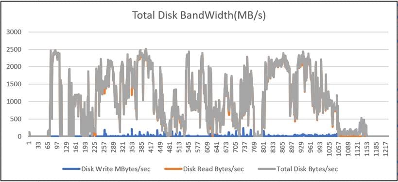
Figure 58 shows the total CPU utilization of the SQL VM during the DSS workload test
Figure 58. SQL VM Processor Utilization during the Test
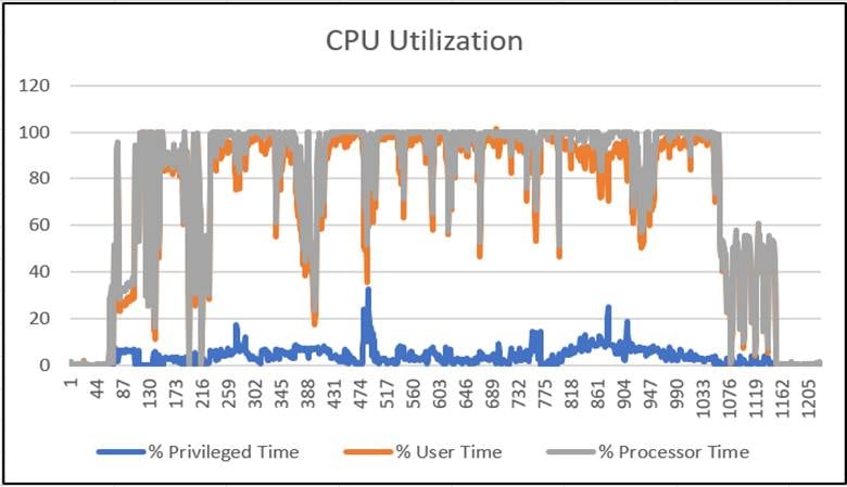
A total bandwidth of 2.5GB/s is achieved from a single SQL VM deployed on a 4-node All-NVMe Cluster. The processor utilization of the VM was consistently 100% during the test. In this scenario, the CPU resources available on the ESXi host are already exhausted by the SQL VM and hence could not assign more CPU resources to the SQL VM. The bandwidth can be scaled up by allocating more CPU resources to the SQL VM. In addition, compute-only node equipped with high core CPUs would be a better option to host VMs running heavy workloads like DSS.
Common Database Maintenance Scenarios
This section describes the common database maintenance activities and provides a few guidelines for planning database maintenance activities on the SQL VMs deployed on the All-NVMe HyperFlex system.
The most common database maintenance activities include export, import, index rebuild, backup, restore and running database consistency checks on regular intervals. The IO pattern of these activities usually differs from business operational workloads hosted on the other VMs in the same cluster. The maintenance activities would typically generate sequential IO when compared to the business transactions, which generate random IO (in case of transactional workloads). When sequential IO pattern is introduced to the system alongside with random IO pattern, there is a possibility of impact on IO sensitive database applications. Hence caution must be exercised while sizing the environment or controlling the impact by running DB maintenance activities during the business hours in production environments. The following list provides some of the guidelines to run the management activities to avoid the impact on business operations:
● As a best practice, all the management activities such as export, import, backup, restore and DB consistency checks must be scheduled to run off business hours when no critical business transactions are running on the underlying HyperFlex system to avoid impact on the ongoing business operations. Another way of limiting the impact is to size the system with appropriate headroom.
● In case of any urgency to run the management activities during business hours, administrators should know the IO limits of hyperconverged systems and plan to run accordingly.
● For clusters running at peak load or near saturation—when exporting a large volume of data from SQL database hosted on any hyperconverged system to any flat files, it should be ensured that the destination files are located outside of the HyperFlex cluster. This will avoid the impact on the other guest VMs running on the same cluster. For small data exports, the destination files can be on the same cluster.
● Most of the import data operations will be followed by recreation of index and statistics in order to update the database metadata pages. Usually Index recreation would cause lot of sequential read and writes hence it is recommended to schedule import data in off business hours.
● Database restore, backup, rebuilding indexes and running database consistency checks typically generate huge sequential IO. Therefore, these activities must be scheduled to run in the out of business hours.
Using a complete guest or database backups, it is not recommended to keep the backups in the same cluster as it would not protect against the scenario where the entire cluster is lost, for example, during a geographic failure, large scale power outage, and so on. Data protection of the virtualized applications that are deployed on the hyperconverged systems are becoming one of the major challenges to the customers. Hence there is a need for most flexible, efficient, and scalable data protection platform.
Cisco HyperFlex has integration with several backup solutions, for example, Cisco HyperFlex™ System’s solution together with Veeam Availability Suite gives customers a flexible, agile, and scalable infrastructure that is protected and easy to deploy. More details on Veeam data protection platform is available here: https://www.cisco.com/c/en/us/td/docs/unified_computing/ucs/UCS_CVDs/hyperflexedge_veeam.html
Workloads are rarely static in their performance needs. They tend to either grow or shrink over time. One of the key advantages of the Cisco HyperFlex architecture is the seamless scalability of the cluster. In scenarios where the existing workload needs to grow – Cisco HyperFlex can handle the scenario by growing the existing cluster’s compute, storage capacity or storage performance capabilities depending on the resource requirement. This gives administrators enough flexibility to right size their environment based on today’s needs without worrying about future growth.
Database Maintenance Tests for iSCSI
In any hyperconverged systems, it is important to assess the impact caused by database maintenance tasks to the regular SQL workloads running on the same cluster. The maintenance activities typically have sequential IO pattern as opposed to random IO pattern of regular OLTP workloads. Usually in typical hyperconverged shared storage environments, caution must be exercised while running DB maintenance activities during the business hours as they may impact the regular operational workloads.
To assess the impact of the database maintenance activities on the ongoing traditional OLTP workload, the following database maintenance activities were carried out a separate SQL Guest VM (in parallel to the eight SQL workload VMs) deployed on the same All-NVMe cluster. The cluster setup used is the same as described in Table 3.
● Full database (100G) restore from an external backup source (backup source residing outside of HX cluster)
● Full database (100G) backup to a file located with HX Cluster
● Rebuilding indexes of three large tables (of size around 50GB)
Note that these maintenance activities were run on a separate SQL VM in parallel to the regular SQL VMs, which were used to exert stress on the cluster up to its 70-75% cluster IO capacity. As expected, full database restore caused 15 to 20% drop in IOPS which is understandable given the full database restore activity (100% sequential writes activity) was done on a cluster which was already exercised to 65-70% resource usage by ongoing OLTP workload. Full database backup has less than 5% impact on the ongoing workloads as HX All-NVMe cluster could accommodate the additional read bandwidth requirement of full database backup. DB Rebuild activity, which is typically involves sequential reads and writes, has an impact of 15-20% on the ongoing workloads.
The amount of impact caused by the maintenance activities would typically depend on the replication factor and percentage of cluster resource utilization in addition to factors such as back up settings and so on. On system with appropriate resource headroom (which is done by right capacity planning), the impact would be much lower. Figure 59 shows the cluster behavior when the maintenance activities such as restore, backup and index rebuild are performed on a VM and when an operational workload is running on the other VMs in the same cluster.
Figure 59. Impact of DB Maintenance Activities on OLTP Workload
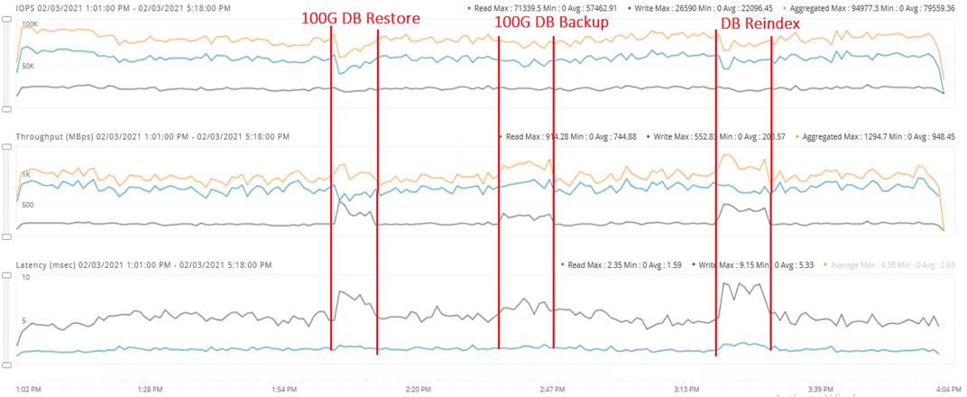
VMware lists the common troubleshooting scenarios for the virtual machines hosted on VMware ESXi cluster here: https://kb.vmware.com/selfservice/microsites/search.do?language=en_US&cmd=displayKC&externalId=2001003
![]() The in-guest performance monitors (like Windows Perfmon) may not be able to collect the performance data which is based on time slices since the time period/interval is abstracted from the virtual machine by the VMware ESXi. Therefore, it is recommended to analyze the ESXTOP metrics for the performance troubleshooting of SQL server virtual machines. More details on interpreting ESXTOP statistics can be found here: https://communities.vmware.com/docs/DOC-9279
The in-guest performance monitors (like Windows Perfmon) may not be able to collect the performance data which is based on time slices since the time period/interval is abstracted from the virtual machine by the VMware ESXi. Therefore, it is recommended to analyze the ESXTOP metrics for the performance troubleshooting of SQL server virtual machines. More details on interpreting ESXTOP statistics can be found here: https://communities.vmware.com/docs/DOC-9279
![]() Tuning the SQL Server transaction/ query performance is out-of-scope for this document.
Tuning the SQL Server transaction/ query performance is out-of-scope for this document.
Some of the commonly seen performance problems on virtualized/ hyperconverged systems are detailed below.
High SQL Guest CPU Utilization
When high guest CPU utilization with lower disk latencies on SQL guest VMs is observed and CPU utilization on ESXi hosts appears to be normal, then it might be the case that virtual machine is experiencing a CPU contention. The solution to overcome this is to add more vCPUs to the virtual machine as the workload is demanding more CPU resources.
When high CPU utilization is observed on both guest and Hosts, then one of the options to be looked at is upgrading to a higher performing processor. More options to solve this issue is mentioned in VMware vSphere documentation here: https://pubs.vmware.com/vsphere-60/index.jsp#com.vmware.vsphere.monitoring.doc/GUID-5F8147A1-6416-4D29-BA3D-E4CED3966016.html
High Disk Latency on SQL Guest
The following guidelines can be used to troubleshoot when higher disk latencies are observed on SQL guest VMs:
● Use ESXTOP charts to identify the guest latencies versus kernel latencies and follow the options mentioned in section Deployment Planning.
● If a higher HX storage capacity utilization nearing expected thresholds occurs (above 60% usage), SQL VMs might also experience IO latencies at both guest and kernel levels; it is recommended to scale up the cluster by adding a new HX node to the cluster.
The Cisco HyperFlex HX Data Platform revolutionizes data storage for hyperconverged infrastructure deployments that support new IT consumption models. The platform’s architecture and software-defined storage approach gives you a purpose-built high-performance distributed file system with a wide array of enterprise class data management services. With innovations that redefine distributed storage technology, the data platform provides you the optimal hyperconverged infrastructure to deliver adaptive IT infrastructure. Cisco HyperFlex systems lower both operating expenses (OpEx) and capital expenditures (CapEx) by allowing you to scale as you grow. They also simplify the convergence of compute, storage, and network resources.
HyperFlex All-NVMe storage system is a purpose build and co-engineered system to cater various enterprise grade applications such as databases which demands low latency and consistent performance. HyperFlex 4.5 support for native iSCSI shared volumes enable customers to deploy SQL Server Failover Cluster Instance(FCI) offering higher availability to the SQL Instances. Customers can leverage iSCSI volumes to run DSS workloads and benefit from consistent higher bandwidth. Customers can also leverage iSCSI clones to take point in time consistent clones for their production databases and use these clones for quickly refreshing their dev/test database environments. The performance and resiliency tests detailed in this document show the robustness of the solution to host OLTP and DSS Microsoft SQL Server database workloads.
HyperFlex 4.5 Administration Guide:
HyperFlex 4.5 Virtual Server Infrastructure CVD:
https://www.cisco.com/c/en/us/td/docs/unified_computing/ucs/UCS_CVDs/hx45_vmw_esxi.html
Managing iSCSI volumes in HyperFlex 4.5
About the Authors
Gopu Narasimha Reddy, Technical Marketing Engineer, Compute Systems Product Group, Cisco Systems, Inc.
Gopu Narasimha Reddy is a Technical Marketing Engineer in the Cisco UCS Datacenter Solutions group. Currently, he is focusing on developing, testing, and validating solutions on the Cisco UCS platform for Microsoft SQL Server databases on Microsoft Windows and VMware platforms. He is also involved in publishing TPC-H database benchmarks on Cisco UCS servers. His areas of interest include building and validating reference architectures, development of sizing tools in addition to assisting customers in SQL deployments.
Acknowledgements
For their support and contribution to the design, validation, and creation of this Cisco Validated Design, the authors would like to thank:
● Vadi Bhatt, Cisco Systems, Inc
● Babu Mahadevan, Cisco Systems, Inc
● Mithlesh Thukral, Cisco Systems, Inc.
● Joost Van Der Made, Cisco Systems, Inc.
Appendix: PowerShell Scripts to Configure Microsoft Initiator and Connect to HyperFlex iSCSI Volumes
SQL VM Configured with One iSCSI Adapter
To configure the SQL VM with one iSCSI adapter, follow these steps:
1. Obtain the iSCSI IP address of the guest, start Microsoft Initiator service, and configure it to start automatically.
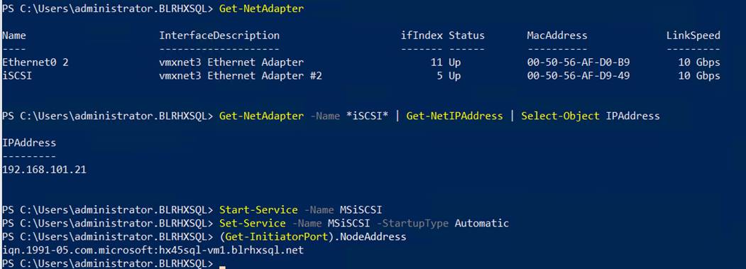
2. Since VM has one initiator IP addresses, establish a connection to the HyperFlex Cluster IP Addresses (CIP) using initiator.
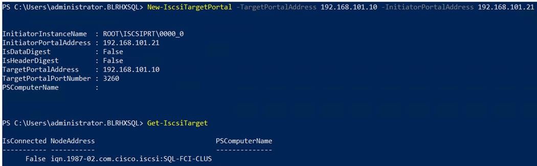
3. Connect to the HyperFlex iSCSI Cluster IP (CIP) using the guest iSCSI address.

4. Since guest has single initiator, there is no need to install and configure MPIO.
SQL VM Configured with Two or More iSCSI Adapters
To configure SQL VM with two or more iSCSI adapters, follow these steps:
1. Obtain the iSCSI IP address of the guest, start Microsoft Initiator service, and configure it to start automatically.
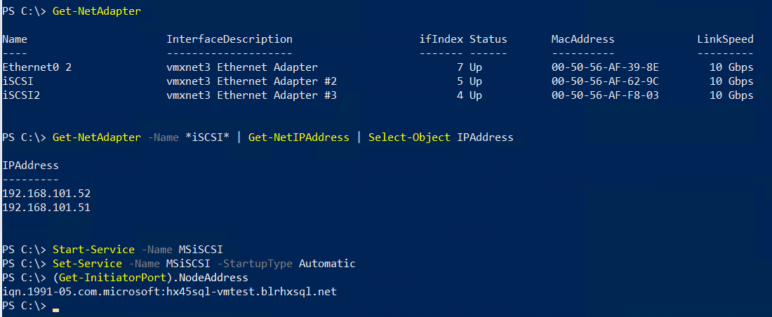
2. Since VM has more than one initiator IP addresses, it is recommended to connect each initiator to a different HyperFlex node target iSCSI IP address as shown below.
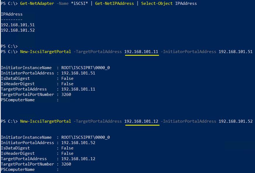
3. Connect each Guest’s iSCSI adapter to two different HyperFlex iSCSI IPs as shown below.
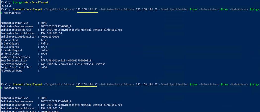
4. Install MPIO feature as shown below and reboot the Guest VM after MPIO utility is installed.
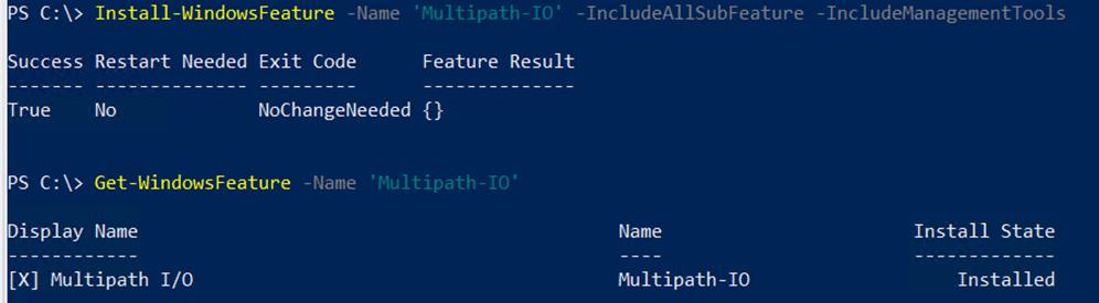
5. Add the HyperFlex Vendor ID and Product ID combination in MDSM supported hardware list by running the below cmdlets.
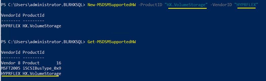
6. Enable MSDSM to automatically claim HyperFlex iSCSI disks for MPIO. Finally restart the guest VM.
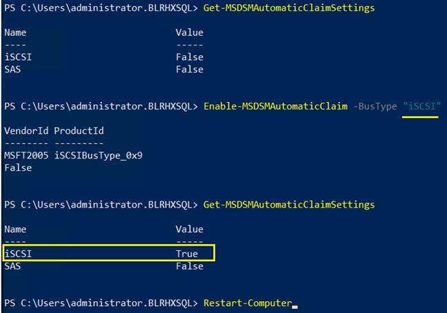
7. When the guest is back online, open disk management tool and select properties of an iSCSI volume. Click on MPIO tab. As there are two initiators in the guest you may see more than one iSCSI connection to the HyperFlex target. Make sure “Round Robin” selected for MPIO policy.
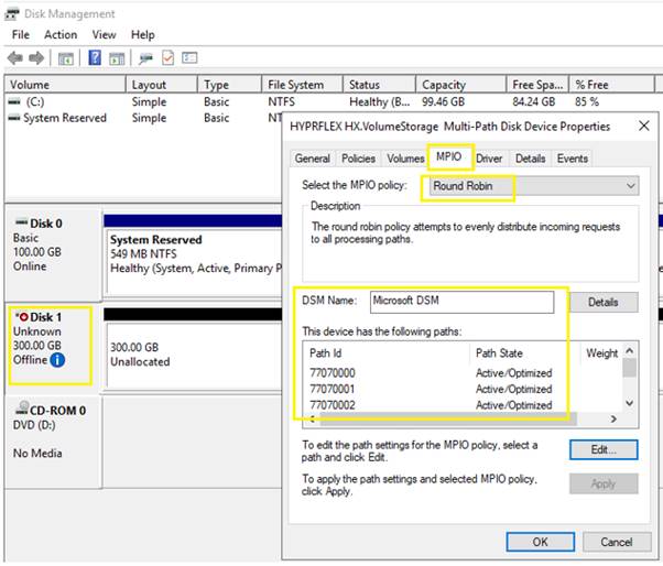
Feedback
For comments and suggestions about this guide and related guides, join the discussion on Cisco Community at https://cs.co/en-cvds.