FlexPod Datacenter with Cisco UCS M6 X-Series for SAP HANA TDI
Available Languages
Bias-Free Language
The documentation set for this product strives to use bias-free language. For the purposes of this documentation set, bias-free is defined as language that does not imply discrimination based on age, disability, gender, racial identity, ethnic identity, sexual orientation, socioeconomic status, and intersectionality. Exceptions may be present in the documentation due to language that is hardcoded in the user interfaces of the product software, language used based on RFP documentation, or language that is used by a referenced third-party product. Learn more about how Cisco is using Inclusive Language.
- US/Canada 800-553-2447
- Worldwide Support Phone Numbers
- All Tools
 Feedback
 Feedback
Published: September 2023
In partnership with:

![]()
About the Cisco Validated Design Program
The Cisco Validated Design (CVD) program consists of systems and solutions designed, tested, and documented to facilitate faster, more reliable, and more predictable customer deployments. For more information, go to: http://www.cisco.com/go/designzone.
Executive Summary
The FlexPod Datacenter solution is a validated approach for deploying Cisco and NetApp technologies and products to build shared private and public cloud infrastructure. Cisco and NetApp have partnered to deliver a series of FlexPod solutions that enable strategic data-center platforms. The success of the FlexPod solution is driven through its ability to evolve and incorporate both technology and product innovations in the areas of management, compute, storage, and networking.
This document covers deployment details of incorporating the Cisco UCS X-Series modular platform into the FlexPod Datacenter for SAP HANA TDI solution and its ability to manage FlexPod components from the cloud using Cisco Intersight. The document explains both configurations and best practices for a successful deployment.
In addition to the compute-specific hardware and software innovations, the integration of the Cisco Intersight cloud platform with VMware vCenter and NetApp Ontap Tools delivers monitoring, orchestration, and workload optimization capabilities for different layers (virtualization and storage) of the FlexPod infrastructure.
If you’re interested in understanding the FlexPod design and deployment details, including the configuration of various elements of design and associated best practices, refer to the Cisco Validated Designs for FlexPod, here: https://www.cisco.com/c/en/us/solutions/design-zone/data-center-design-guides/flexpod-design-guides.html.
Deployment Hardware and Software
This chapter contains the following:
The FlexPod Datacenter with Cisco UCS and Intersight meets the following general design requirements:
● Resilient design across all layers of the infrastructure with no single point of failure
● Scalable design with the flexibility to add compute capacity, storage, or network bandwidth as needed
● Modular design that can be replicated to expand and grow as the needs of the business grow
● Flexible design that can support different models of various components with ease
● Simplified design with ability to integrate and automate with external automation tools
● Cloud-enabled design which can be configured, managed, and orchestrated from the cloud using GUI or APIs
To deliver a solution which meets all these design requirements, various solution components are connected and configured as explained in the upcoming sections.
The FlexPod Datacenter solution is built using the following hardware components:
● Cisco UCS X9508 Chassis with Cisco UCS 9108 25G Intelligent Fabric Modules (IFMs) and up to eight Cisco UCS X210c M6 Compute Nodes with 3rd Generation Intel Xeon Scalable CPUs
● Fourth-generation Cisco UCS 6454 Fabric Interconnects to support 100GbE, 25GbE, and 32GFC connectivity from various components
● High-speed Cisco NX-OS-based Nexus 93180YC-FX3 switching design to support up to 100GE connectivity
● NetApp AFF A400 storage with 100G Ethernet and (optional) 32G Fibre Channel connectivity
● Cisco MDS 9132T* switches to support Fibre Channel storage configuration
Note: * Cisco MDS 9132T and FC connectivity is not needed when implementing IP-based connectivity design supporting iSCSI boot from SAN and NFS.
The software components of the solution consist of:
● Cisco Intersight SaaS platform to deploy, maintain and support the FlexPod components
● Cisco Intersight Assist Virtual Appliance to help connect NetApp ONTAP, VMware vCenter, and Cisco Nexus and MDS switches with Cisco Intersight
● NetApp Active IQ Unified Manager to monitor and manage the storage and for NetApp ONTAP integration with Cisco Intersight
● VMware vCenter to set up and manage the virtual infrastructure as well as Cisco Intersight integration
FlexPod Datacenter for IP-based Storage Access
Figure 1 shows various hardware components and the network connections for the IP/NFS only FlexPod design.
Figure 1. FlexPod Datacenter Physical Topology for IP-based Storage Access
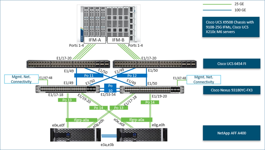
The reference hardware configuration includes:
● Two Cisco Nexus 93180YC-FX3 Switches in Cisco NX-OS mode provide the switching fabric.
● Two Cisco UCS 6454 Fabric Interconnects (FI) provide the chassis connectivity. One 100 Gigabit Ethernet port from each FI, configured as a Port-Channel, is connected to each Cisco Nexus 93180YC-FX3.
● One Cisco UCS X9508 Chassis connects to fabric interconnects using Cisco UCS 9108 25G Intelligent Fabric Modules (IFMs), where four 25G Gigabit Ethernet ports are used on each IFM to connect to the appropriate FI.
● One NetApp AFF A400 HA pair connects to the Cisco Nexus 93180YC-FX3 Switches using four 25 GE ports from each controller configured as a Port-Channel.
FlexPod Datacenter for FC-based Storage Access
Figure 2 shows various hardware components and the network connections for primarily FC-based FlexPod design.
Figure 2. FlexPod Datacenter Physical Topology for FC-based Storage Access
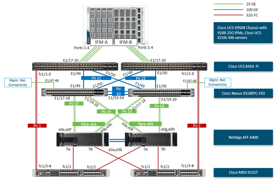
The reference hardware configuration includes:
● Two Cisco Nexus 93180YC-FX3 Switches in Cisco NX-OS mode provide the switching fabric.
● Two Cisco UCS 6454 Fabric Interconnects (FI) provide the chassis connectivity. One 100 Gigabit Ethernet port from each FI, configured as a Port-Channel, is connected to each Cisco Nexus 93180YC-FX3. Two FC ports from each FI are connected to the respective Cisco MDS 9132T switches using 32-Gbps Fibre Channel connections configured as a port channel for SAN connectivity.
● One Cisco UCS X9508 Chassis connects to fabric interconnects using Cisco UCS 9108 25G Intelligent Fabric Modules (IFMs), where four 25 Gigabit Ethernet ports are used on each IFM to connect to the appropriate FI. If additional bandwidth is required, all eight 25G ports can be utilized.
● One NetApp AFF A400 HA pair connects to the Cisco Nexus 93180YC-FX3 Switches using four 25 GE ports from each controller configured as a Port-Channel. Two 32Gbps FC ports from each controller are connected to each Cisco MDS 9132T for SAN connectivity.
Note: The NetApp storage controller and disk shelves should be connected according to best practices for the specific storage controller and disk shelves. For disk shelf cabling, refer to NetApp Support: https://docs.netapp.com/us-en/ontap-systems/index.html
VLAN Configuration
Table 1 lists VLANs configured for setting up the FlexPod environment along with their usage. For the validation example, the scale-up SAP HANA system is configured with backup, system replication and shared filesystem networks. Both bare-metal and virtualized scenarios are considered and VLANs for both are listed in Table 1.
| VLAN ID |
Name |
Usage |
| 2 |
Native-VLAN |
Use VLAN 2 as native VLAN instead of default VLAN (1). |
| 1070 |
OOB-MGMT |
Out-of-band management VLAN to connect management ports for various devices. |
| 1071 |
IB-MGMT |
In-band management VLAN utilized for all in-band management connectivity - for example, Admin network for ESXi hosts, VM management, and so on. |
| 1072 |
vMotion *** |
VMware vMotion traffic. |
| 1073 |
HANA-Replication |
HANA system replication network |
| 1074 |
HANA-Data |
SAP HANA Data NFS filesystem network for IP/NFS only solution** |
| 1075 |
Infra-NFS *** |
NFS VLAN for mounting datastores in ESXi servers for VM boot disks** |
| 1076 |
HANA-Log |
SAP HANA Log NFS filesystem network for IP/NFS only solution** |
| 1077 |
HANA-Shared |
SAP HANA shared filesystem network** |
| 1078* |
iSCSI-A |
iSCSI-A path for storage traffic including boot-from-san traffic** |
| 1079* |
iSCSI-B |
iSCSI-B path for storage traffic including boot-from-san traffic** |
| 75 |
Infra-Backup |
Backup server network** |
| 76 |
HANA-Appserver |
SAP Application server network |
* iSCSI VLANs are not required if using FC storage access.
** IP gateway is not needed since no routing is required for these subnets
***Only needed for Virtualized SAP HANA use-cases.
Some of the key highlights of VLAN usage are as follows:
● VLAN 1070 allows customers to manage and access out-of-band management interfaces of various devices.
● VLAN 1071 is used for in-band management of VMs, ESXi hosts, admin network in case of bare-metal system and other infrastructure services.
● VLAN 1072 is used for VM vMotion
● VLANs 1073, 76 are used for SAP HANA system traffic – for example, system replication and SAP Application server network.
● VLAN 1074 and 1076 are used for SAP HANA Data and Log NFS networks – only needed in IP only solution and virtualized SAP HANA system for SAP HANA data and log filesystem mounts.
● VLAN 1075 provides ESXi SAP HANA hosts access to the NFS datastores hosted on the NetApp Controllers for deploying VMs.
● VLAN 1077 provides SAP HANA nodes access to HANA shared filesystem and additionally HANA shared persistence volumes in case of virtualized SAP HANA.
● A pair of iSCSI VLANs (1078 and 1079) is configured to provide access to boot LUNs for ESXi hosts or bare-metal SAP HANA nodes. These VLANs are not needed if customers are using FC-only connectivity.
● VLAN 75 is the datacenter backup network
Table 2 lists the infrastructure VMs necessary for deployment as outlined in this document. The VLAN and IP address tabs provide the values used in the lab configuration.
| Virtual Machine Description |
VLAN |
Comments |
| vCenter Server |
1071 |
Hosted on either pre-existing management infrastructure (in this case) or on FlexPod |
| Cisco Intersight Assist |
1071 |
Hosted on either pre-existing management infrastructure (in this case) or on FlexPod |
| NetApp ONTAP Tools |
1071 |
Hosted on FlexPod |
| NetApp SnapCenter for vSphere |
1071 |
Hosted on FlexPod |
| Active IQ Unified Manager |
1071 |
Hosted on FlexPod |
Table 3 lists the software revisions for various components of the solution.
| Layer |
Device |
Image Bundle |
Comments |
| Compute |
Cisco UCS |
4.2(3d) |
Cisco UCS GA release for infrastructure including FIs and IOM/IFM. |
| Network |
Cisco Nexus 93180YC-FX3 NX-OS |
9.3(7) |
|
| Cisco MDS 9132T |
9.3(2) |
Requires SMART Licensing |
|
| Storage |
NetApp AFF A400 |
NetApp ONTAP 9.12.1P2 |
|
| Software |
Cisco UCS X210c M6 |
5.0(4b) |
Cisco UCS X-series GA release for compute nodes |
| Cisco Intersight Assist Appliance |
1.0.9-589 |
1.0.9-538 initially installed and then automatically upgraded |
|
| VMware vCenter |
7.0 Update 3l |
Build 21477706 |
|
| VMware ESXi |
7.0 Update 3i |
Build 20842708 included in Cisco Custom ISO |
|
| VMware ESXi nfnic FC Driver |
5.0.0.37 |
|
|
| VMware ESXi nenic Ethernet Driver |
1.0.45.0 |
|
|
| NetApp ONTAP Tools for VMware vSphere |
9.12 |
Formerly Virtual Storage Console (VSC) |
|
| NetApp NFS Plug-in for VMware VAAI |
2.0.1 |
|
|
| NetApp SnapCenter for vSphere |
4.9 |
Includes the vSphere plug-in for SnapCenter |
|
| NetApp Active IQ Unified Manager |
9.12 |
|
|
|
|
|
|
This chapter contains the following:
● Cisco Nexus Switch Manual Configuration
This chapter provides a detailed procedure for configuring the Cisco Nexus 93180YC-FX3 switches for use in a FlexPod environment. The Cisco Nexus 93180YC-FX3 will be used for LAN switching in this solution.
Note: Both switches have been reset to factory defaults by using the “write erase” command followed by the “reload” command.
Follow the physical connectivity guidelines for FlexPod explained in section Physical Topology.
The following procedures describe this basic configuration of the Cisco Nexus switches for use in the FlexPod environment. This procedure assumes the use of Cisco Nexus 9000 10.2(3)M, the Cisco suggested Cisco Nexus switch release at the time of this validation.
Procedure 1. Set Up Initial Configuration for Cisco Nexus A Switch <nexus-A-hostname> from Serial Console
Step 1. Configure the switch.
Note: On initial boot, the NX-OS setup should automatically start and attempt to enter Power on Auto Provisioning.
Abort Power On Auto Provisioning [yes - continue with normal setup, skip - bypass password and basic configuration, no - continue with Power On Auto Provisioning] (yes/skip/no)[no]: yes
Disabling POAP.......Disabling POAP
poap: Rolling back, please wait... (This may take 5-15 minutes)
---- System Admin Account Setup ----
Do you want to enforce secure password standard (yes/no) [y]: Enter
Enter the password for "admin": <password>
Confirm the password for "admin": <password>
Would you like to enter the basic configuration dialog (yes/no): yes
Create another login account (yes/no) [n]: Enter
Configure read-only SNMP community string (yes/no) [n]: Enter
Configure read-write SNMP community string (yes/no) [n]: Enter
Enter the switch name: <nexus-A-hostname>
Continue with Out-of-band (mgmt0) management configuration? (yes/no) [y]: Enter
Mgmt0 IPv4 address: <nexus-A-out_of_band_mgmt0-ip>
Mgmt0 IPv4 netmask: <nexus-A-mgmt0-netmask>
Configure the default gateway? (yes/no) [y]: Enter
IPv4 address of the default gateway: <nexus-A-mgmt0-gw>
Configure advanced IP options? (yes/no) [n]: Enter
Enable the telnet service? (yes/no) [n]: Enter
Enable the ssh service? (yes/no) [y]: Enter
Type of ssh key you would like to generate (dsa/rsa) [rsa]: Enter
Number of rsa key bits <1024-2048> [1024]: Enter
Configure the ntp server? (yes/no) [n]: Enter
Configure default interface layer (L3/L2) [L2]: Enter
Configure default switchport interface state (shut/noshut) [noshut]: shut
Enter basic FC configurations (yes/no) [n]: n
Configure CoPP system profile (strict/moderate/lenient/dense) [strict]: Enter
Would you like to edit the configuration? (yes/no) [n]: Enter
Step 2. Review the configuration summary before enabling the configuration.
Use this configuration and save it? (yes/no) [y]: Enter
Step 3. To set up the initial configuration of the Cisco Nexus B switch, repeat steps 1 and 2 with the appropriate host and IP address information.
Cisco Nexus Switch Manual Configuration
Procedure 1. Enable Cisco Nexus Features on Cisco Nexus A and Cisco Nexus B
Step 1. Log in as admin using ssh.
Step 2. Run the following commands:
config t
feature nxapi
feature udld
feature interface-vlan
feature lacp
feature vpc
feature lldp
Procedure 2. Set Global Configurations on Cisco Nexus A and Cisco Nexus B
Note: To set global configurations, follow this step on both switches.
Step 1. Run the following commands to set global configurations:
spanning-tree port type network default
spanning-tree port type edge bpduguard default
spanning-tree port type edge bpdufilter default
port-channel load-balance src-dst l4port
ip name-server <dns-server-1> <dns-server-2>
ip domain-name <dns-domain-name>
ip domain-lookup
ntp server <global-ntp-server-ip> use-vrf management
ntp master 3
clock timezone <timezone> <hour-offset> <minute-offset>
(For Example: clock timezone EST -5 0)
clock summer-time <timezone> <start-week> <start-day> <start-month> <start-time> <end-week> <end-day> <end-month> <end-time> <offset-minutes>
(For Example: clock summer-time EDT 2 Sunday March 02:00 1 Sunday November 02:00 60)
copy run start
ip route 0.0.0.0/0 <ib-mgmt-vlan-gateway>
Note: For more information on configuring the timezone and daylight savings time or summer time, see Cisco Nexus 9000 Series NX-OS Fundamentals Configuration Guide, Release 10.2(x).
Procedure 3. Create VLANs on Cisco Nexus A and Cisco Nexus B
Note: To create the necessary virtual local area networks (VLANs), follow this step on both switches:
Step 1. From the global configuration mode, run the following commands:
vlan <native-vlan-id for example, 2>
name native-vlan
vlan <infra-backup-vlan-id for example, 75>
name infra-backup
vlan <HANA-Appserver-vlan-id for example, 76>
name HANA-Appserver
vlan <oob-mgmt-vlan-id for example, 1070>
name oob-mgmt
vlan <ib-mgmt-vlan-id for example, 1071>
name ib-mgmt
vlan <vMotion-vlan-id for example, 1072>
name vMotion
vlan <HANA-Replicationp-vlan-id for example, 1073>
name HANA-Replication
vlan <HANA-Data-vlan-id for example 1074>
name HANA-Data
vlan <infra-nfs-vlan-id for example, 1075>
name infra-nfs
vlan <HANA-Log-vlan-id for example, 1076>
name HANA-og
vlan <HANA-Shared-vlan-id for example, 1077>
name HANA-Shared
Step 2. If configuring iSCSI storage access, create the following two additional VLANs:
vlan <iscsi-a-vlan-id for example, 1078>
name infra-iscsi-a
vlan <iscsi-b-vlan-id for example, 1079>
name infra-iscsi-b
Procedure 4. Create Port Channels
Cisco Nexus A
Note: For fibre optic connections to Cisco UCS systems (AOC or SFP-based), entering udld enable will result in a message stating that this command is not applicable to fiber ports. This message is expected. This command will enable UDLD on Twinax connections.
Step 1. From the global configuration mode, run the following commands:
interface Po10
description vPC peer-link
!
interface Eth1/53
description <nexus-b-hostname>:Eth1/53
!
interface Eth1/54
description <nexus-b-hostname>:Eth1/54
!
interface Eth1/53-54
channel-group 10 mode active
no shutdown
!
! UCS Connectivity
!
description <ucs-domainname>-a
!
interface Eth1/49
udld enable
description <ucs-domainname>-a:Eth1/49
channel-group 197 mode active
no shutdown
!
interface Po12
description <ucs-domainname>-b
!
interface Eth1/50
udld enable
description <ucs-domainname>-b:Eth1/49
channel-group 12 mode active
no shutdown
!
! Storage Connectivity
!
interface Po19
description <st-clustername>-01
!
interface Eth1/9
description <st-clustername>-01:e0e
channel-group 19 mode active
no shutdown
!
interface Eth1/10
description <st-clustername>-01:e0f
channel-group 19 mode active
no shutdown
!
interface Po111
description <st-clustername>-02
!
interface Eth1/11
description <st-clustername>-02:e0e
channel-group 111 mode active
no shutdown
!
interface Eth1/12
description <st-clustername>-02:e0f
channel-group 111 mode active
no shutdown
!
! Uplink Switch Connectivity
!
interface Po107
description MGMT-Uplink
!
interface Eth1/47
description <mgmt-uplink-switch-a-hostname>:<port>
channel-group 107 mode active
no shutdown
!
interface Eth1/48
description <mgmt-uplink-switch-b-hostname>:<port>
channel-group 107 mode active
no shutdown
exit
copy run start
Cisco Nexus B
Note: For fibre optic connections to Cisco UCS systems (AOC or SFP-based), entering udld enable will result in a message stating that this command is not applicable to fiber ports. This message is expected. This command will enable UDLD on Twinax connections.
Step 1. From the global configuration mode, run the following commands:
interface Po10
description vPC peer-link
!
interface Eth1/53
description <nexus-a-hostname>:Eth1/53
!
interface Eth1/54
description <nexus-a-hostname>:Eth1/54
!
interface Eth1/53-54
channel-group 10 mode active
no shutdown
!
! UCS Connectivity
!
interface Po11
description <ucs-domainname>-a
!
interface Eth1/49
udld enable
description <ucs-domainname>-a:Eth1/50
channel-group 11 mode active
no shutdown
!
interface Po12
description <ucs-domainname>-b
!
interface Eth1/50
udld enable
description <ucs-domainname>-b:Eth1/50
channel-group 12 mode active
no shutdown
!
! Storage Connectivity
!
interface Po19
description <st-clustername>-01
!
interface Eth1/9
description <st-clustername>-01:e0g
channel-group 13 mode active
no shutdown
!
interface Eth1/10
description <st-clustername>-01:e0h
channel-group 19 mode active
no shutdown
!
interface Po111
description <st-clustername>-02
!
interface Eth1/11
description <st-clustername>-02:e0g
channel-group 111 mode active
no shutdown
!
interface Eth1/12
description <st-clustername>-02:e0h
channel-group 111 mode active
no shutdown
!
! Uplink Switch Connectivity
!
interface Po107
description MGMT-Uplink
!
interface Eth1/47
description <mgmt-uplink-switch-a-hostname>:<port>
channel-group 107 mode active
no shutdown
!
interface Eth1/48
description <mgmt-uplink-switch-b-hostname>:<port>
channel-group 107 mode active
no shutdown
exit
copy run start
Procedure 5. Configure Port Channel Parameters on Cisco Nexus A and Cisco Nexus B
Note: iSCSI VLANs in these steps are only configured when setting up storage access for these protocols.
Step 1. From the global configuration mode, run the following commands to setup VPC Peer-Link port-channel:
interface Po10
switchport mode trunk
switchport trunk native vlan <native-vlan-id>
switchport trunk allowed vlan <oob-mgmt-vlan-id>,<ib-mgmt-vlan-id>,<infra-nfs-vlan-id>,<infra-backup-vlan-id> <vMotion-vlan-id>, <iscsi-a-vlan-id>,<iscsi-b-vlan-id>,<HANA-Replication-vlan-id>,<HANA-Data-vlan-id>,<HANA-Log-vlan-id>,<HANA-Shared-vlan-id>,<HANA-Appserver-vlan-id>
spanning-tree port type network
Step 2. From the global configuration mode, run the following commands to setup port-channels for UCS FI 6454 connectivity:
interface Po11
switchport mode trunk
switchport trunk native vlan <native-vlan-id>
switchport trunk allowed vlan <oob-mgmt-vlan-id>,<ib-mgmt-vlan-id>,<infra-nfs-vlan-id>,<infra-backup-vlan-id> <vMotion-vlan-id>, <iscsi-a-vlan-id>,<iscsi-b-vlan-id>,<HANA-Replication-vlan-id>,<HANA-Data-vlan-id>,<HANA-Log-vlan-id>,<HANA-Shared-vlan-id>,<HANA-Appserver-vlan-id>
spanning-tree port type edge trunk
mtu 9216
!
interface Po112
switchport mode trunk
switchport trunk native vlan <native-vlan-id>
switchport trunk allowed vlan <oob-mgmt-vlan-id>,<ib-mgmt-vlan-id>,<infra-nfs-vlan-id>,<infra-backup-vlan-id> <vMotion-vlan-id>, <iscsi-a-vlan-id>,<iscsi-b-vlan-id>,<HANA-Replication-vlan-id>,<HANA-Data-vlan-id>,<HANA-Log-vlan-id>,<HANA-Shared-vlan-id>,<HANA-Appserver-vlan-id>
spanning-tree port type edge trunk
mtu 9216
Step 3. From the global configuration mode, run the following commands to setup port-channels for NetApp A400 connectivity:
interface Po19
switchport mode trunk
switchport trunk native vlan <native-vlan-id>
switchport trunk allowed vlan <ib-mgmt-vlan-id>,<infra-nfs-vlan-id>,<iscsi-a-vlan-id>,<iscsi-b-vlan-id>,<HANA-Data-vlan-id>,<HANA-Log-vlan-id>,<HANA-Shared-vlan-id>
spanning-tree port type edge trunk
mtu 9216
!
interface Po111
switchport mode trunk
switchport trunk native vlan <native-vlan-id>
switchport trunk allowed vlan <ib-mgmt-vlan-id>,<infra-nfs-vlan-id>,<iscsi-a-vlan-id>,<iscsi-b-vlan-id>,<HANA-Data-vlan-id>,<HANA-Log-vlan-id>,<HANA-Shared-vlan-id>
spanning-tree port type edge trunk
mtu 9216
Step 4. From the global configuration mode, run the following commands to setup port-channels for connectivity to existing management switch(es):
Note: For networks needing gateway access and if that is configured via connectivity to core switches, you should include those networks here.
interface Po107
switchport mode trunk
switchport trunk native vlan <native-vlan-id>
switchport trunk allowed vlan <oob-mgmt-vlan-id>,<ib-mgmt-vlan-id>,<infra-nfs-vlan-id>,<infra-backup-vlan-id> <vMotion-vlan-id>,<HANA-Replication-vlan-id
spanning-tree port type network
mtu 9216
!
exit
copy run start
Procedure 6. Configure Virtual Port Channels
Cisco Nexus A
Step 1. From the global configuration mode, run the following commands:
vpc domain <nexus-vpc-domain-id for example, 10>
role priority 10
peer-keepalive destination <nexus-B-mgmt0-ip> source <nexus-A-mgmt0-ip>
peer-switch
peer-gateway
auto-recovery
delay restore 150
ip arp synchronize
!
interface Po10
vpc peer-link
!
interface Po11
vpc 11
!
interface Po12
vpc 12
!
interface Po19
vpc 19
!
interface Po111
vpc 111
!
interface Po107
vpc 107
!
exit
copy run start
Cisco Nexus B
Step 1. From the global configuration mode, run the following commands:
vpc domain <nexus-vpc-domain-id for example, 10>
role priority 20
peer-keepalive destination <nexus-A-mgmt0-ip> source <nexus-B-mgmt0-ip>
peer-switch
peer-gateway
auto-recovery
delay restore 150
ip arp synchronize
!
interface Po10
vpc peer-link
!
interface Po11
vpc 11
!
interface Po12
vpc 12
!
interface Po19
vpc 19
!
interface Po111
vpc 111
!
interface Po107
vpc 107
!
exit
copy run start
NetApp ONTAP Storage Configuration
This chapter contains the following:
NetApp AFF A400/A800 Controllers
See section NetApp Hardware Universe for planning the physical location of the storage systems:
● Site Preparation
● System Connectivity Requirements
● Circuit Breaker, Power Outlet Balancing, System Cabinet Power Cord Plugs, and Console Pinout Requirements
● AFF Series Systems
To confirm that the hardware and software components that you would like to use are supported with the version of NetApp ONTAP that you plan to install, follow the steps at the NetApp Support site.
Procedure 1. Confirm hardware and software components
Step 1. Access the HWU application to view the System Configuration guides. Click the Platforms menu to view the compatibility between different versions of the NetApp ONTAP software and the NetApp storage appliances with your desired specifications.
Step 2. Alternatively, to compare components by storage appliance, click Compare Storage Systems.
Follow the physical installation procedures for the controllers here: https://docs.netapp.com/us-en/ontap-systems/index.html.
NetApp storage systems support a wide variety of disk shelves and disk drives. The complete list of disk shelves that are supported by the AFF A400 and AFF A800 is available at the NetApp Support site.
When using SAS disk shelves with NetApp storage controllers, refer to: https://docs.netapp.com/us-en/ontap-systems/sas3/index.html for proper cabling guidelines.
When using NVMe drive shelves with NetApp storage controllers, refer to: https://docs.netapp.com/us-en/ontap-systems/ns224/index.html for installation and servicing guidelines.
Complete Configuration Worksheet
Before running the setup script, complete the Cluster setup worksheet in the NetApp ONTAP 9 Documentation Center. You must have access to the NetApp Support site to open the cluster setup worksheet.
Before running the setup script, review the configuration worksheets in the Software setup section of the NetApp ONTAP 9 Documentation Center to learn about configuring NetApp ONTAP. Table 4 lists the information needed to configure two NetApp ONTAP nodes. Customize the cluster-detail values with the information applicable to your deployment.
Table 4. NetApp ONTAP Software Installation Prerequisites
| Cluster Detail |
Cluster Detail Value |
| Cluster node 01 IP address |
<node01-mgmt-ip> |
| Cluster node 01 netmask |
<node01-mgmt-mask> |
| Cluster node 01 gateway |
<node01-mgmt-gateway> |
| Cluster node 02 IP address |
<node02-mgmt-ip> |
| Cluster node 02 netmask |
<node02-mgmt-mask> |
| Cluster node 02 gateway |
<node02-mgmt-gateway> |
| ONTAP 9.12URL (http server hosting NetApp ONTAP software) |
<url-boot-software> |
Procedure 1. Configure Node 01
Step 1. Connect to the storage system console port. You should see a Loader-A prompt. However, if the storage system is in a reboot loop, press Ctrl-C to exit the autoboot loop when the following message displays:
Starting AUTOBOOT press Ctrl-C to abort…
Step 2. Allow the system to boot up.
autoboot
Step 3. Press Ctrl-C when prompted.
Note: If NetApp ONTAP 9.12.1P2 is not the version of the software being booted, continue with the following steps to install new software. If NetApp ONTAP 9.12.1P2 is the version being booted, select option 8 and y to reboot the node, then continue with section Set Up Node.
Step 4. To install new software, select option 7 from the menu.
Step 5. Enter y to continue the installation.
Step 6. Select e0M for the network port for the download.
Step 7. Enter n to skip the reboot.
Step 8. Select option 7 from the menu: Install new software first
Step 9. Enter y to continue the installation.
Step 10. Enter the IP address, netmask, and default gateway for e0M.
Enter the IP address for port e0M: <node01-mgmt-ip>
Enter the netmask for port e0M: <node01-mgmt-mask>
Enter the IP address of the default gateway: <node01-mgmt-gateway>
Step 11. Enter the URL where the software can be found.
Note: The e0M interface should be connected to the management network and the web server must be reachable (using ping) from node 01.
<url-boot-software>
Step 12. Press Enter for the user name, indicating no user name.
Step 13. Enter y to set the newly installed software as the default to be used for subsequent reboots.
Step 14. Enter y to reboot the node.
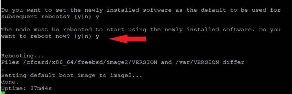
Note: When installing new software, the system might perform firmware upgrades to the BIOS and adapter cards, causing reboots and possible stops at the Loader-A prompt. If these actions occur, the system might deviate from this procedure.
Note: During the NetApp ONTAP installation a prompt to reboot the node requests a Y/N response.
Step 15. Press Ctrl-C when the following message displays:
Press Ctrl-C for Boot Menu
Step 16. Select option 4 for Clean Configuration and Initialize All Disks.
Step 17. Enter y to zero disks, reset config, and install a new file system.
Step 18. Enter yes to erase all the data on the disks.
Note: The initialization and creation of the root aggregate can take 90 minutes or more to complete, depending on the number and type of disks attached. When initialization is complete, the storage system reboots. Note that SSDs take considerably less time to initialize. You can continue with the configuration of node 02 while the disks for node 01 are zeroing.
Procedure 2. Configure Node 02
Step 1. Connect to the storage system console port. You should see a Loader-B prompt. However, if the storage system is in a reboot loop, press Ctrl-C to exit the autoboot loop when the following message displays:
Starting AUTOBOOT press Ctrl-C to abort…
Step 2. Allow the system to boot up.
autoboot
Step 3. Press Ctrl-C when prompted.
Note: If NetApp ONTAP 9.12.1P2 is not the version of the software being booted, continue with the following steps to install new software. If NetApp ONTAP 9.12.1P2 is the version being booted, select option 8 and y to reboot the node. Then continue with section Set Up Node.
Step 4. To install new software, select option 7.
Step 5. Enter y to continue the installation.
Step 6. Select e0M for the network port you want to use for the download.
Step 7. Enter n to skip the reboot.
Step 8. Select option 7: Install new software first
Step 9. Enter y to continue the installation.
Step 10. Enter the IP address, netmask, and default gateway for e0M.
Enter the IP address for port e0M: <node02-mgmt-ip>
Enter the netmask for port e0M: <node02-mgmt-mask>
Enter the IP address of the default gateway: <node02-mgmt-gateway>
Step 11. Enter the URL where the software can be found.
Note: The web server must be reachable (ping) from node 02.
<url-boot-software>
Step 12. Press Enter for the username, indicating no user name.
Step 13. Enter y to set the newly installed software as the default to be used for subsequent reboots.
Step 14. Enter y to reboot the node now.
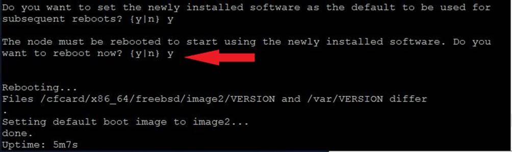
Note: When installing new software, the system might perform firmware upgrades to the BIOS and adapter cards, causing reboots and possible stops at the Loader-B prompt. If these actions occur, the system might deviate from this procedure.
Note: During the NetApp ONTAP installation a prompt to reboot the node requests a Y/N response.
Step 15. Press Ctrl-C when you see this message:
Press Ctrl-C for Boot Menu
Step 16. Select option 4 for Clean Configuration and Initialize All Disks.
Step 17. Enter y to zero disks, reset config, and install a new file system.
Step 18. Enter yes to erase all the data on the disks.
Note: The initialization and creation of the root aggregate can take 90 minutes or more to complete, depending on the number and type of disks attached. When initialization is complete, the storage system reboots. Note that SSDs take considerably less time to initialize.
Procedure 3. Set Up Nodes and cluster
Step 1. From a console port program attached to the storage controller A (node 01) console port, run the node setup script. This script appears when NetApp ONTAP 9.12.1P2 boots on the node for the first time.
Step 2. Follow the prompts to set up node 01.
Welcome to the cluster setup wizard.
You can enter the following commands at any time:
"help" or "?" - if you want to have a question clarified,
"back" - if you want to change previously answered questions, and
"exit" or "quit" - if you want to quit the setup wizard.
Any changes you made before quitting will be saved.
You can return to cluster setup at any time by typing “cluster setup”.
To accept a default or omit a question, do not enter a value.
This system will send event messages and weekly reports to NetApp Technical Support.
To disable this feature, enter "autosupport modify -support disable" within 24 hours.
Enabling AutoSupport can significantly speed problem determination and resolution should a problem occur on your system.
For further information on AutoSupport, see:
http://support.netapp.com/autosupport/
Type yes to confirm and continue {yes}: yes
Enter the node management interface port [e0M]: Enter
Enter the node management interface IP address: <node01-mgmt-ip>
Enter the node management interface netmask: <node01-mgmt-mask>
Enter the node management interface default gateway: <node01-mgmt-gateway>
A node management interface on port e0M with IP address <node01-mgmt-ip> has been created.
Use your web browser to complete cluster setup by accesing https://<node01-mgmt-ip>
Otherwise press Enter to complete cluster setup using the command line interface:
Step 3. To complete cluster setup, open a web browser and navigate to https://<node01-mgmt-ip>.
Table 5. Cluster Create in NetApp ONTAP Prerequisites
| Cluster Detail |
Cluster Detail Value |
| Cluster name |
<clustername> |
| NetApp ONTAP base license |
<cluster-base-license-key> |
| Cluster management IP address |
<clustermgmt-ip> |
| Cluster management netmask |
<clustermgmt-mask> |
| Cluster management gateway |
<clustermgmt-gateway> |
| Cluster node 01 IP address |
<node01-mgmt-ip> |
| Cluster node 01 netmask |
<node01-mgmt-mask> |
| Cluster node 01 gateway |
<node01-mgmt-gateway> |
| Cluster node 02 IP address |
<node02-mgmt-ip> |
| Cluster node 02 netmask |
<node02-mgmt-mask> |
| Cluster node 02 gateway |
<node02-mgmt-gateway> |
| Node 01 service processor IP address |
<node01-sp-ip> |
| Node 01 service processor network mask |
<node01-sp-mask> |
| Node 01 service processor gateway |
<node01-sp-gateway> |
| Node 02 service processor IP address |
<node02-sp-ip> |
| Node 02 service processor network mask |
<node02-sp-mask> |
| Node 02 service processor gateway |
<node02-sp-gateway> |
| Node 01 node name |
<st-node01> |
| Node 02 node name |
<st-node02> |
| DNS domain name |
<dns-domain-name> |
| DNS server IP address |
<dns-ip> |
| NTP server A IP address |
<switch-a-ntp-ip> |
| NTP server B IP address |
<switch-b-ntp-ip> |
| SNMPv3 User |
<snmp-v3-usr> |
| SNMPv3 Authentication Protocol |
<snmp-v3-auth-proto> |
| SNMPv3 Privacy Protocol |
<snmpv3-priv-proto> |
Note: The cluster setup can also be performed using the NetApp ONTAP System Manager guided setup. This document describes the cluster setup using the CLI.
Step 4. Press Enter to continue the cluster setup via CLI.
Step 5. Create a new cluster.
Do you want to create a new cluster or join an existing cluster? {create, join}:
Create
Step 6. Press Enter for default option of “no” to setup a single node cluster.
Do you intend for this node to be used as a single node cluster? {yes, no} [no]:
Step 7. Create the cluster interface configuration. Select yes if you want to use the default settings.
Existing cluster interface configuration found:
Port MTU IP Netmask
e3a 9000 169.254.142.30 255.255.0.0
e3b 9000 169.254.41.219 255.255.0.0
Do you want to use this configuration? {yes, no} [yes]:
Step 8. Provide the cluster administrator’s password.
Enter the cluster administrator's (username "admin") password:
Retype the password:
Step 9. Create the cluster, provide a cluster name.
Step 1 of 5: Create a Cluster
You can type "back", "exit", or "help" at any question.
Enter the cluster name: <clustername>
Creating cluster <clustername>
.
Starting replication service
Starting replication service .
Starting replication service ..
System start up
System start up .
System start up ..
System start up ...
System start up ....
System start up .....
Updating LIF Manager
Vserver Management
Starting cluster support services
Starting cluster support services .
Starting cluster support services ..
Cluster <clustername> has been created.
Step 10. Add the needed license keys.
Step 2 of 5: Add Feature License Keys
You can type "back", "exit", or "help" at any question.
Enter an additional license key []: <cluster-base-license-key>
Step 11. Create the vserver for cluster administration.
Step 3 of 5: Set Up a Vserver for Cluster Administration
You can type "back", "exit", or "help" at any question.
Enter the cluster management interface port [e0e]: e0M
Enter the cluster management interface IP address: <clustermgmt-ip>
Enter the cluster management interface netmask: <clustermgmt-mask>
Enter the cluster management interface default gateway [<clustermgmt-gateway>]:
A cluster management interface on port e0M with IP address <clustermgmt-ip> has been created. You can use this address to connect to and manage the cluster.
Step 12. Provide the DNS domain names and DNS server IP address.
Enter the DNS domain names: <dns-domain-name>
Enter the DNS server IP addresses: <dns-ip>
Step 13. Finish the first part of the setup.
Step 4 of 5: Configure Storage Failover (SFO)
You can type "back", "exit", or "help" at any question.
SFO will be enabled when the partner joins the cluster.
Step 5 of 5: Set Up the Node
You can type "back", "exit", or "help" at any question.
Where is the controller located []: <snmp-location>
Cluster "<clustername>" has been created.
To complete cluster setup, you must join each additional node to the cluster
by running "system node show-discovered" and "cluster add-node" from a node in the cluster.
To complete system configuration, you can use either OnCommand System Manager
or the Data ONTAP command-line interface.
To access OnCommand System Manager, point your web browser to the cluster
management IP address (https:// <clustermgmt-ip>).
To access the command-line interface, connect to the cluster management
IP address (for example, ssh admin@<clustermgmt-ip>).
Step 14. From a console port program attached to the storage controller B (node 02) console port, run the node setup script. This script appears when ONTAP boots on the node for the first time.
Step 15. Follow the prompts to set up node 02:
Welcome to the cluster setup wizard.
You can enter the following commands at any time:
"help" or "?" - if you want to have a question clarified,
"back" - if you want to change previously answered questions, and
"exit" or "quit" - if you want to quit the cluster setup wizard.
Any changes you made before quitting will be saved.
You can return to cluster setup at any time by typing "cluster setup".
To accept a default or omit a question, do not enter a value.
This system will send event messages and periodic reports to NetApp Technical
Support. To disable this feature, enter
autosupport modify -support disable
within 24 hours.
Enabling AutoSupport can significantly speed problem determination and
resolution, should a problem occur on your system.
For further information on AutoSupport, see:
http://support.netapp.com/autosupport/
Type yes to confirm and continue {yes}: yes
Enter the node management interface port [e0M]: Enter
Enter the node management interface IP address: <node02-mgmt-ip>
Enter the node management interface netmask: <node02-mgmt-mask>
Enter the node management interface default gateway: <node02-mgmt-gateway>
A node management interface on port e0M with IP address <node02-mgmt-ip> has been created
Use your web browser to complete cluster setup by accessing https://<node02-mgmt-ip>
Otherwise, press Enter to complete cluster setup using the command line
interface:
Step 16. Press Enter to continue the cluster setup via CLI.
Step 17. Join the new cluster.
Do you want to create a new cluster or join an existing cluster? {create, join}:
join
Step 18. Create the cluster interface configuration. Select yes if you want to use the default settings.
Existing cluster interface configuration found:
Port MTU IP Netmask
e3a 9000 169.254.57.171 255.255.0.0
e3b 9000 169.254.79.119 255.255.0.0
Do you want to use this configuration? {yes, no} [yes]:
Step 19. Enter an IP address of the private cluster network from node 1.
Step 1 of 3: Join an Existing Cluster
You can type "back", "exit", or "help" at any question.
Enter the IP address of an interface on the private cluster network from the
cluster you want to join: 169.254.142.30
Joining cluster at address 169.254.142.30
.
Joining cluster
Joining cluster .
System start up
System start up .
System start up ..
System start up ...
System start up ....
System start up .....
Starting cluster support services
This node has joined the cluster <clustername>.
Step 20. Finish the second part of the setup.
Step 2 of 3: Configure Storage Failover (SFO)
You can type "back", "exit", or "help" at any question.
SFO will be enabled when the partner joins the cluster.
Step 3 of 3: Set Up the Node
You can type "back", "exit", or "help" at any question.
This node has been joined to cluster "<clustername>".
To complete cluster setup, you must join each additional node to the cluster
by running "system node show-discovered" and "cluster add-node" from a node in the cluster.
To complete system configuration, you can use either OnCommand System Manager
or the Data ONTAP command-line interface.
To access OnCommand System Manager, point your web browser to the cluster
management IP address (https:// <clustermgmt-ip>).
To access the command-line interface, connect to the cluster management
IP address (for example, ssh admin@<clustermgmt-ip>).
Procedure 4. Log into the Cluster
Step 1. Open an SSH connection to either the cluster IP or the host name.
Step 2. Log into the admin user with the password you provided earlier.
Procedure 5. Verify Storage Failover
Step 1. Verify the status of the storage failover.
storage failover show
Node Partner Possible State Description
-------------- -------------- -------- -------------------------------------
AA07-A400-01 AA07-A400-02 true Connected to AA07-A400-02
AA07-A400-02 AA07-A400-01 true Connected to AA07-A400-01
2 entries were displayed.
Note: Both <st-node01> and <st-node02> must be capable of performing a takeover. Continue with Step 2 if the nodes can perform a takeover.
Step 2. Enable failover on one of the two nodes if it was not completed during the installation.
storage failover modify -node <st-node01> -enabled true
Note: Enabling failover on one node enables it for both nodes.
Step 3. Verify the HA status for a two-node cluster.
Note: This step is not applicable for clusters with more than two nodes.
cluster ha show
Step 4. If HA is not configured use the below commands. Only enable HA mode for two-node clusters. Do not run this command for clusters with more than two nodes because it causes problems with failover.
cluster ha modify -configured true
Do you want to continue? {y|n}: y
Step 5. Verify that hardware assist is correctly configured.
storage failover hwassist show
High-Availability Configured: true
Step 6. If hwassist storage failover is not enabled, enable using the following commands:
storage failover modify –hwassist-partner-ip <node02-mgmt-ip> -node <st-node01>
storage failover modify –hwassist-partner-ip <node01-mgmt-ip> -node <st-node02>
Procedure 6. Set Auto-Revert Parameter on Cluster Management Interface
Step 1. Run the following command:
network interface modify -vserver <clustername> -lif cluster_mgmt_lif -auto-revert true
Note: A storage virtual machine (SVM) is referred to as a Vserver or vserver in the GUI and CLI.
Procedure 7. Set Up Service Processor Network Interface
Step 1. To assign a static IPv4 address to the Service Processor on each node, run the following commands:
system service-processor network modify –node <st-node01> -address-family IPv4 –enable true –dhcp none –ip-address <node01-sp-ip> -netmask <node01-sp-mask> -gateway <node01-sp-gateway>
system service-processor network modify –node <st-node02> -address-family IPv4 –enable true –dhcp none –ip-address <node02-sp-ip> -netmask <node02-sp-mask> -gateway <node02-sp-gateway>
Note: The Service Processor IP addresses should be in the same subnet as the node management IP addresses.
Procedure 8. Zero All Spare Disks
Step 1. To zero all spare disks in the cluster, run the following command:
disk zerospares
Note: Advanced Data Partitioning creates a root partition and two data partitions on each SSD drive in an AFF configuration. Disk auto-assign should have assigned one data partition to each node in an HA pair. If a different disk assignment is required, disk auto-assignment must be disabled on both nodes in the HA pair by running the disk option modify command. Spare partitions can then be moved from one node to another by running the disk removeowner and disk assign commands.
Procedure 9. Create Aggregates
An aggregate containing the root volume is created during the NetApp ONTAP setup process. To manually create additional aggregates, determine the aggregate name, the node on which to create it, and the number of disks it should contain. Options for disk type include SAS, SSD, and SSD-NVM.
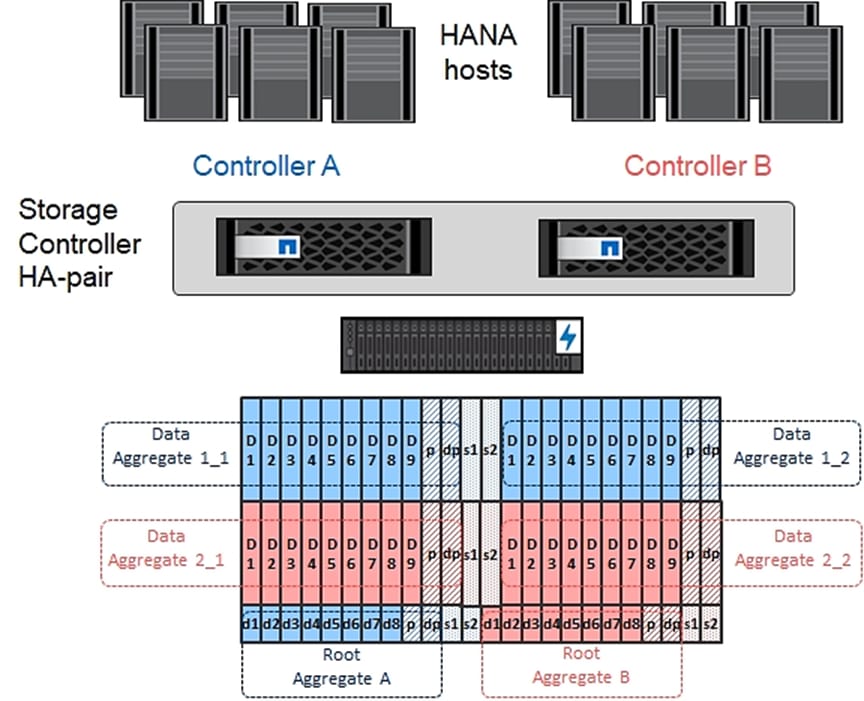
Step 1. To create new aggregates, run the following commands:
aggr create -aggregate aggr1_1 -node <clustername>-1 -diskcount 11
aggr create -aggregate aggr1_2 -node <clustername>-2 -diskcount 11
aggr create -aggregate aggr2_1 -node <clustername>-1 -diskcount 11
aggr create -aggregate aggr2_2 -node <clustername>-2 -diskcount 11
Use all disks except for two spares to create the aggregates. In this example 11 disks per aggregate were used
Optional: Rename the root aggregate on node 01 to match the naming convention for this aggregate on node 02. The aggregate is automatically renamed if system-guided setup is used.
aggr show
aggr rename –aggregate aggr0 –newname <node01-rootaggrname>
Note: You should have the minimum number of hot spare disks for the recommended hot spare disk partitions for the aggregate.
Note: For all-flash aggregates, you should have a minimum of one hot spare disk or disk partition. For non-flash homogenous aggregates, you should have a minimum of two hot spare disks or disk partitions. For Flash Pool aggregates, you should have a minimum of two hot spare disks or disk partitions for each disk type.
Note: In an AFF configuration with a small number of SSDs, you might want to create an aggregate with all, but one remaining disk (spare) assigned to the controller.
Note: The aggregate cannot be created until disk zeroing completes. Run the storage aggregate show command to display the aggregate creation status. Do not proceed until all aggregates are online.
Procedure 10. Remove Default Broadcast Domains
By default, all network ports are included in separate default broadcast domain. Network ports used for data services (for example, e0g, e0e, and e0f) should be removed from their default broadcast domain and that broadcast domain should be deleted.
Step 1. To perform this task, run the following commands:
network port broadcast-domain delete -broadcast-domain <Default-N> -ipspace Default
network port broadcast-domain show
Note: Delete the Default broadcast domains with Network ports (Default-1, Default-2, and so on). This does not include Cluster ports and management ports.
Procedure 11. Disable Flow Control on 25/100GbE Data Ports
NetApp recommends disabling flow control on all the 25/40/100GbE ports that are connected to external devices. To disable flow control, complete the following steps:
Step 1. Run the following command to configure the ports on node 01:
network port modify -node <st-node01> -port e3a,e3b -flowcontrol-admin none
network port modify -node <st-node01> -port e0e,e0f,e0g,e0h -flowcontrol-admin none
Step 2. Run the following command to configure the ports on node 02:
network port modify -node <st-node02> -port e3a,e3b -flowcontrol-admin none
network port modify -node <st-node02> -port e0e,e0f,e0g,e0h -flowcontrol-admin none
Note: Disable flow control only on ports that are used for data traffic.
AA07-A400::> net port show -node * -port e0e,e0f,e0g,e0h -fields speed-admin,duplex-admin,flowcontrol-admin
(network port show)
node port duplex-admin speed-admin flowcontrol-admin
------------ ---- ------------ ----------- -----------------
AA07-A400-01 e0e auto auto none
AA07-A400-01 e0f auto auto none
AA07-A400-01 e0g auto auto none
AA07-A400-01 e0h auto auto none
AA07-A400-02 e0e auto auto none
AA07-A400-02 e0f auto auto none
AA07-A400-02 e0g auto auto none
AA07-A400-02 e0h auto auto none
8 entries were displayed.
AA07-A400::> net port show -node * -port e3a,e3b -fields speed-admin,duplex-admin,flowcontrol-admin
(network port show)
node port duplex-admin speed-admin flowcontrol-admin
------------ ---- ------------ ----------- -----------------
AA07-A400-01 e3a auto auto none
AA07-A400-01 e3b auto auto none
AA07-A400-02 e3a auto auto none
AA07-A400-02 e3b auto auto none
4 entries were displayed.
Procedure 12. Disable Auto-Negotiate on Fibre Channel Ports (Required only for FC configuration)
Step 1. Disable each FC adapter in the controllers with the fcp adapter modify command.
fcp adapter modify -node <st-node01> -adapter 5a –status-admin down
fcp adapter modify -node <st-node01> -adapter 5b –status-admin down
fcp adapter modify -node <st-node01> -adapter 5c –status-admin down
fcp adapter modify -node <st-node01> -adapter 5d –status-admin down
fcp adapter modify -node <st-node02> -adapter 5a –status-admin down
fcp adapter modify -node <st-node02> -adapter 5b –status-admin down
fcp adapter modify -node <st-node02> -adapter 5c –status-admin down
fcp adapter modify -node <st-node02> -adapter 5d –status-admin down
Note: In the lab setup, only ports 5a and 5b on both controllers were utilized.
Step 2. Set the desired speed on the adapter and return it to the online state.
fcp adapter modify -node <st-node01> -adapter 5a -speed 32 -status-admin up
fcp adapter modify -node <st-node01> -adapter 5b -speed 32 -status-admin up
fcp adapter modify -node <st-node02> -adapter 5a -speed 32 -status-admin up
fcp adapter modify -node <st-node02> -adapter 5b -speed 32 -status-admin up
Procedure 13. Verify FCP ports are set to target ports.
Step 1. Change the FCP to target mode if they are configured as initiator. Check the ports if they configured correctly:
system node hardware unified-connect show
Current Current Pending Pending Admin
Node Adapter Mode Type Mode Type Status
------------ ------- ------- --------- ------- --------- -----------
<clustername>-01 5a fc initiator - - online
<clustername>-01 5b fc initiator - - online
<clustername>-01 5c fc initiator - - offline
<clustername>-01 5d fc initiator - - offline
<clustername>-02 5a fc initiator - - online
<clustername>-02 5b fc initiator - - online
<clustername>-02 5c fc initiator - - offline
<clustername>-02 5d fc initiator - - offline
8 entries were displayed.
Step 2. Disable all ports that need to be changed:
system node run -node <clustername>-01 -command storage disable adapter 5a
system node run -node <clustername>-01 -command storage disable adapter 5b
system node run -node <clustername>-02 -command storage disable adapter 5a
system node run -node <clustername>-02 -command storage disable adapter 5b
Step 3. Change the HBAs mode to target:
ucadmin modify -node <clustername>-* -adapter 5a -type target
Warning: FC-4 type on adapter 5b will also be changed to target.
Do you want to continue? {y|n}: y
Any changes will take effect after rebooting the system. Use the "system node reboot" command to reboot.
Any changes will take effect after rebooting the system. Use the "system node reboot" command to reboot.
2 entries were modified.
Step 4. Reboot each controller node:
node reboot -node <clustername>-01
Step 5. Wait until the first node is back up and running and reboot the second node:
node reboot -node <clustername>-01
Step 6. Verification:
AA07-A400::> system node hardware unified-connect show
Current Current Pending Pending Admin
Node Adapter Mode Type Mode Type Status
------------ ------- ------- --------- ------- --------- -----------
AA07-A400-01 5a fc target - - online
AA07-A400-01 5b fc target - - online
AA07-A400-01 5c fc target - - offline
AA07-A400-01 5d fc target - - offline
AA07-A400-02 5a fc target - - online
AA07-A400-02 5b fc target - - online
AA07-A400-02 5c fc target - - offline
AA07-A400-02 5d fc target - - offline
8 entries were displayed.
Procedure 14. Enable Cisco Discovery Protocol
Step 1. To enable the Cisco Discovery Protocol (CDP) on the NetApp storage controllers, run the following command:
node run -node * options cdpd.enable on
Procedure 15. Enable Link-layer Discovery Protocol on all Ethernet Ports
Step 1. Enable LLDP on all ports of all nodes in the cluster:
node run * options lldp.enable on
Procedure 16. Configure Timezone Synchronization on the cluster
Step 1. Set the time zone for the cluster.
timezone -timezone <timezone>
Note: For example, in the eastern United States, the time zone is America/New_York.
Procedure 17. Create Management Broadcast Domain
Step 1. If the management interfaces are required to be on a separate VLAN, create a new broadcast domain for those interfaces by running the following command:
network port broadcast-domain create -broadcast-domain AA07-SVM-MGMT -mtu 1500
Procedure 18. Create NFS Broadcast Domain
Step 1. To create an NFS data broadcast domain with a maximum transmission unit (MTU) of 9000, run the following commands in NetApp ONTAP:
network port broadcast-domain create -broadcast-domain AA07-Infra-NFS -mtu 9000
Procedure 19. Create ISCSI Broadcast Domains (Required only for iSCSI configuration)
Step 1. To create an ISCSI-A and ISCSI-B data broadcast domain with a maximum transmission unit (MTU) of 9000, run the following commands in NetApp ONTAP:
network port broadcast-domain create -broadcast-domain AA07-iSCSI-A -mtu 9000
network port broadcast-domain create -broadcast-domain AA07-iSCSI-B -mtu 9000
Procedure 20. Create Interface Groups
Step 1. To create the LACP interface groups for the 25GbE data interfaces, run the following commands:
network port ifgrp create -node <st-node01> -ifgrp a0a -distr-func port -mode multimode_lacp
network port ifgrp add-port -node <st-node01> -ifgrp a0a -port e0e
network port ifgrp add-port -node <st-node01> -ifgrp a0a -port e0f
network port ifgrp add-port -node <st-node01> -ifgrp a0a -port e0g
network port ifgrp add-port -node <st-node01> -ifgrp a0a -port e0h
network port ifgrp create -node <st-node02> -ifgrp a0a -distr-func port -mode multimode_lacp
network port ifgrp add-port -node <st-node02> -ifgrp a0a -port e0e
network port ifgrp add-port -node <st-node02> -ifgrp a0a -port e0f
network port ifgrp add-port -node <st-node02> -ifgrp a0a -port e0g
network port ifgrp add-port -node <st-node02> -ifgrp a0a -port e0h
To verify:
AA07-A400::> network port ifgrp show
Port Distribution Active
Node IfGrp Function MAC Address Ports Ports
-------- ---------- ------------ ----------------- ------- -------------------
AA07-A400-01
a0a port d2:39:ea:29:d4:4a full e0e, e0f, e0g, e0h
AA07-A400-02
a0a port d2:39:ea:29:ce:d5 full e0e, e0f, e0g, e0h
2 entries were displayed.
Procedure 21. Change MTU on Interface Groups
Step 1. To change the MTU size on the base interface-group ports before creating the VLAN ports, run the following commands:
network port modify –node <st-node01> -port a0a –mtu 9000
network port modify –node <st-node02> -port a0a –mtu 9000
To verify:
AA07-A400::> network port show -node AA07-A400-01 -port a0a -fields mtu
node port mtu
------------ ---- ----
AA07-A400-01 a0a 9000
AA07-A400::> network port show -node AA07-A400-02 -port a0a -fields mtu
node port mtu
------------ ---- ----
AA07-A400-02 a0a 9000
Step 1. Create the management VLAN ports and add them to the management broadcast domain.
network port vlan create –node <st-node01> -vlan-name a0a-<ib-mgmt-vlan-id>
network port vlan create –node <st-node02> -vlan-name a0a-<ib-mgmt-vlan-id>
network port broadcast-domain add-ports -broadcast-domain AA07-SVM-MGMT -ports <st-node01>:a0a-<ib-mgmt-vlan-id>,<st-node02>:a0a-<ib-mgmt-vlan-id>
Step 2. Create the NFS VLAN ports and add them to the Infra-NFS broadcast domain.
network port vlan create –node <st-node01> -vlan-name a0a-<infra-nfs-vlan-id>
network port vlan create –node <st-node02> -vlan-name a0a-<infra-nfs-vlan-id>
network port broadcast-domain add-ports -broadcast-domain AA07-Infra-NFS -ports <st-node01>:a0a-<infra-nfs-vlan-id>,<st-node02>:a0a-<infra-nfs-vlan-id>
Step 3. If configuring iSCSI, create iSCSI VLAN ports for the iSCSI LIFs on each storage controller and add them to the corresponding broadcast domain:
network port vlan create -node <st-node01> -vlan-name a0a-<iscsi-a-vlan-id>
network port vlan create -node <st-node01> -vlan-name a0a-<iscsi-b-vlan-id>
network port vlan create -node <st-node02> -vlan-name a0a-<iscsi-a-vlan-id>
network port vlan create -node <st-node02> -vlan-name a0a-<iscsi-b-vlan-id>
network port broadcast-domain add-ports -broadcast-domain AA07-iSCSI-A -ports <st-node01>:a0a-<iscsi-a-vlan-id>
network port broadcast-domain add-ports -broadcast-domain AA07-iSCSI-B -ports <st-node01>:a0a-<iscsi-b-vlan-id>
network port broadcast-domain add-ports -broadcast-domain AA07-iSCSI-A -ports <st-node02>:a0a-<infra-iscsi-a-vlan-id>
network port broadcast-domain add-ports -broadcast-domain AA07-iSCSI-B -ports <st-node02>:a0a-<infra-iscsi-b-vlan-id>
Step 4. Verification:
AA07-A400::> broadcast-domain show -ipspace Default
(network port broadcast-domain show)
IPspace Broadcast Update
Name Domain Name MTU Port List Status Details
------- ----------- ------ ----------------------------- --------------
Default AA07-Infra-NFS 9000
AA07-A400-02:a0a-1075 complete
AA07-A400-01:a0a-1075 complete
AA07-SVM-MGMT 1500
AA07-A400-02:a0a-1071 complete
AA07-A400-01:a0a-1071 complete
AA07-iSCSI-A 9000
AA07-A400-02:a0a-1078 complete
AA07-A400-01:a0a-1078 complete
AA07-iSCSI-B 9000
AA07-A400-02:a0a-1079 complete
AA07-A400-01:a0a-1079 complete
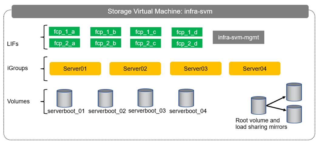
Configure SVM for the Infrastructure
Figure 3 describe the infrastructure SVM together with all required storage objects (volumes and LIFs).
Figure 3. Overview of Infrastructure SVM Components
Procedure 23. Create SVM (Storage Virtual Machine) for Infrastructure
Step 1. Run the vserver create command.
vserver create –vserver <Infra-SVM> –rootvolume infra_svm_root –aggregate aggr2_1 –rootvolume-security-style unix
Step 2. Add the required data protocols to the SVM:
vserver add-protocols -protocols nfs,iscsi,fcp -vserver <Infra-SVM>
Step 3. Remove the unused data protocols from the SVM:
vserver remove-protocols –vserver <Infra-SVM> -protocols cifs,nvme
Note: It is recommended to remove iSCSI or FCP protocols if the protocol is not in use.
Step 4. Add the two data aggregates to the Infra-SVM aggregate list for the NetApp ONTAP Tools.
vserver modify –vserver <Infra-SVM> –aggr-list aggr1_1,aggr2_1,aggr1_2,aggr2_2
Step 5. Enable and run the NFS protocol in the Infra-SVM.
vserver nfs create -vserver <Infra-SVM> -udp disabled -v3 enabled -v4.1 enabled -vstorage enabled
Note: If the NFS license was not installed during the cluster configuration, make sure to install the license before starting the NFS service.
Procedure 24. Vserver Protocol Verification
Step 1. Verify the required protocols are added to the Infra-SVM vserver.
AA07-A400::> vserver show-protocols -vserver AA07-Infra-SVM
Vserver: AA07-Infra-SVM
Protocols: nfs, fcp, iscsi
Step 2. If a protocol is not present, use the following command to add the protocol to the vserver:
vserver add-protocols -vserver <Infra-SVM> -protocols <iscsi or fcp>
Procedure 25. Create Load-Sharing Mirrors of SVM Root Volume
Step 1. Create a volume to be the load-sharing mirror of the infrastructure SVM root volume on each node.
volume create –vserver <Infra-SVM> –volume infra_svm_root_m01 –aggregate aggr2_1 –size 1GB –type DP
volume create –vserver <Infra-SVM> –volume infra_svm_root_m02 –aggregate aggr2_2 –size 1GB –type DP
Step 2. Create the mirroring relationships.
snapmirror create –source-path <Infra-SVM>:infra_svm_root -destination-path AA07-Infra-SVM:infra_svm_root_m01 –type LS -schedule 5min
snapmirror create –source-path <Infra-SVM>:infra_svm_root –destination-path AA07-Infra-SVM:infra_svm_root_m02 –type LS -schedule 5min
Step 3. Initialize the mirroring relationship.
snapmirror initialize-ls-set –source-path <Infra-SVM>:infra_svm_root
Procedure 26. Set password for SVM vsadmin user and unlock the user
Step 1. Set a password for the SVM vsadmin user and unlock the user by running the following commands:
security login password –username vsadmin –vserver AA07-Infra-SVM
Enter a new password: <password>
Enter it again: <password>
security login unlock –username vsadmin –vserver AA07-Infra-SVM
Procedure 27. Configure export policy rule
Step 1. Create a new rule for the infrastructure NFS subnet in the default export policy.
vserver export-policy rule create –vserver AA07-Infra-SVM -policyname default –ruleindex 1 –protocol nfs -clientmatch <infra-nfs-subnet-cidr> -rorule sys –rwrule sys -superuser sys –allow-suid true
Step 2. Assign the FlexPod export policy to the infrastructure SVM root volume.
volume modify –vserver AA07-Infra-SVM –volume infra_svm_root –policy default
Procedure 28. Create FlexVol Volumes
The following information is required to create a NetApp FlexVol volume:
● The volume name
● The volume size
● The aggregate on which the volume exists
Step 1. To create FlexVols for datastores, run the following commands:
volume create -vserver AA07-Infra-SVM -volume infra_datastore_1 -aggregate aggr1_1 -size 1TB -state online -policy default -junction-path /infra_datastore_1 -space-guarantee none -percent-snapshot-space 0
Step 2. To create swap volumes, run the following command:
volume create -vserver AA07-Infra-SVM -volume infra_swap -aggregate <aggr1_node01> -size 200GB -state online - policy default -junction-path /infra_swap -space-guarantee none -percent-snapshot-space 0 -snapshot-policy
none
Step 3. To create a FlexVol for the boot LUNs of servers, run the following command:
volume create -vserver AA07-Infra-SVM -volume server_boot -aggregate <aggr1_node01> -size 1TB -state online -
policy default -space-guarantee none -percent-snapshot-space 0
Step 4. Create vCLS datastores to be used by the vSphere environment to host vSphere Cluster Services (vCLS) VMs using the command below:
volume create -vserver Infra-SVM -volume vCLS -aggregate <aggr1_node01> -size 100GB -state online -
policy default -junction-path /vCLS -space-guarantee none -percent-snapshot-space 0 -snapshot-policy none
Step 5. Update set of load-sharing mirrors using the command below:
snapmirror update-ls-set -source-path Infra-SVM:infra_svm_root
Note: If you are going to setup and use SnapCenter to backup the infra_datastore_1 volume, add “-snapshot-policy none” to the end of the volume create command for the infra_datastore_1 volume.
Procedure 29. Disable Volume Efficiency on swap volume
Step 1. On NetApp AFF systems, deduplication is enabled by default. To disable the efficiency policy on the infra_swap volume, run the following command:
volume efficiency off –vserver AA07-Infra-SVM –volume infra_swap
Step 1. To create NFS LIFs, run the following commands:
network interface create -vserver AA07-Infra-SVM -lif nfs-lif-01 -service-policy default-data-files -home-node <st-node01> -home-port a0a-<infra-nfs-vlan-id> –address <node01-nfs-lif-01-ip> -netmask <node01-nfs-lif-01-mask> -status-admin up –failover-policy broadcast-domain-wide –auto-revert true
network interface create -vserver AA07-Infra-SVM -lif nfs-lif-02 -service-policy default-data-files -home-node <st-node02> -home-port a0a-<infra-nfs-vlan-id> –address <node02-nfs-lif-02-ip> -netmask <node02-nfs-lif-02-mask>> -status-admin up –failover-policy broadcast-domain-wide –auto-revert true
Note: For the tasks using network interface create command, the -role and -firewall-policy parameters have been deprecated and may be removed in a future version of NetApp ONTAP. Use the -service-policy parameter instead.
Procedure 31. Create FC LIFs (required only for FC configuration)
Step 1. Run the following commands to create four FC LIFs (two on each node):
network interface create -vserver AA07-Infra-SVM -lif fcp-lif-01a -data-protocol fcp -home-node <st-node01> -home-port 5a –status-admin up
network interface create -vserver AA07-Infra-SVM -lif fcp-lif-01b -data-protocol fcp -home-node <st-node01> -home-port 5b –status-admin up
network interface create -vserver AA07-Infra-SVM -lif fcp-lif-02a -data-protocol fcp -home-node <st-node02> -home-port 5a –status-admin up
network interface create -vserver AA07-Infra-SVM -lif fcp-lif-02b -data-protocol fcp -home-node <st-node02> -home-port 5b –status-admin up
Step 2. Verification:
AA07-A400::> network interface show -vserver AA07-Infra-SVM -data-protocol fcp
Logical Status Network Current Current Is
Vserver Interface Admin/Oper Address/Mask Node Port Home
----------- ---------- ---------- ------------------ ------------- ------- ----
AA07-Infra-SVM
fcp-lif-01a up/up 20:12:d0:39:ea:29:ce:d4
AA07-A400-01 5a true
fcp-lif-01b up/up 20:13:d0:39:ea:29:ce:d4
AA07-A400-01 5b true
fcp-lif-02a up/up 20:0f:d0:39:ea:29:ce:d4
AA07-A400-02 5a true
fcp-lif-02b up/up 20:1e:d0:39:ea:29:ce:d4
AA07-A400-02 5b true
4 entries were displayed.
Procedure 32. Create iSCSI LIFs (required only for iSCSI configuration)
Step 1. To create four iSCSI LIFs, run the following commands (two on each node):
network interface create -vserver AA07-Infra-SVM -lif iscsi-lif-01a -service-policy default-data-iscsi -home-node <st-node01> -home-port a0a-<iscsi-a-vlan-id> -address <st-node01-iscsi-a–ip> -netmask <iscsi-a-mask> -status-admin up
network interface create -vserver AA07-Infra-SVM -lif iscsi-lif-01b -service-policy default-data-iscsi -home-node <st-node01> -home-port a0a-<iscsi-b-vlan-id> -address <st-node01-iscsi-b–ip> -netmask <iscsi-b-mask> –status-admin up
network interface create -vserver AA07-Infra-SVM -lif iscsi-lif-02a -service-policy default-data-iscsi -home-node <st-node02> -home-port a0a-<iscsi-a-vlan-id> -address <st-node02-iscsi-a–ip> -netmask <iscsi-a-mask> –status-admin up
network interface create -vserver AA07-Infra-SVM -lif iscsi-lif-02b -service-policy default-data-iscsi -home-node <st-node02> -home-port a0a-<iscsi-b-vlan-id> -address <st-node02-iscsi-b–ip> -netmask <iscsi-b-mask> –status-admin up
Step 2. Verification:
AA07-A400::> network interface show -vserver AA07-Infra-SVM -data-protocol iscsi
Logical Status Network Current Current Is
Vserver Interface Admin/Oper Address/Mask Node Port Home
----------- ---------- ---------- ------------------ ------------- ------- ----
AA07-Infra-SVM
iscsi-lif-01a
up/up 10.107.8.1/24 AA07-A400-01 a0a-1078
true
iscsi-lif-01b
up/up 10.107.9.1/24 AA07-A400-01 a0a-1079
true
iscsi-lif-02a
up/up 10.107.8.2/24 AA07-A400-02 a0a-1078
true
iscsi-lif-02b
up/up 10.107.9.2/24 AA07-A400-02 a0a-1079
true
4 entries were displayed.
Procedure 33. Create SVM management LIF (Add Infrastructure SVM Administrator)
Step 1. Run the following commands:
network interface create –vserver AA07-Infra-SVM –lif svm-mgmt -service-policy default-management –home-node <st-node01> -home-port a0a-<ib-mgmt-vlan-id> –address <svm-mgmt-ip> -netmask <svm-mgmt-mask> -status-admin up –failover-policy broadcast-domain-wide –auto-revert true
Note: A cluster serves data through at least one and possibly several SVMs. These steps have been created for a single data SVM. Customers can create additional SVMs depending on their requirement.
Procedure 34. Configure AutoSupport
Step 1. NetApp AutoSupport sends support summary information to NetApp through HTTPS. To configure AutoSupport using command-line interface, run the following command:
system node autosupport modify -node * -state enable –mail-hosts <mailhost> -transport https -support enable -noteto <storage-admin-email>
Cisco Intersight Managed Mode Configuration
This chapter contains the following:
● Cisco Intersight Managed Mode Set Up
● Cisco UCS IMM Manual Configuration
● Cisco UCS IMM Setup Completion
The Cisco Intersight platform is a management solution delivered as a service with embedded analytics for Cisco and third-party IT infrastructures. The Cisco Intersight managed mode (also referred to as Cisco IMM or Intersight managed mode) is a architecture that manages Cisco Unified Computing System (Cisco UCS) fabric interconnect–attached systems through a Redfish-based standard model. Cisco Intersight managed mode standardizes both policy and operation management for Cisco UCS B200 M6 and Cisco UCSX X210c M6 compute nodes used in this deployment guide.
Cisco UCS C-Series M6 servers, connected and managed through Cisco UCS FIs, are also supported by IMM. For a complete list of supported platforms, visit: https://www.cisco.com/c/en/us/td/docs/unified_computing/Intersight/b_Intersight_Managed_Mode_Configuration_Guide/b_intersight_managed_mode_guide_chapter_01010.html
Cisco Intersight Managed Mode Set Up
Procedure 1. Set up Cisco Intersight Managed Mode on Cisco UCS Fabric Interconnects
The Cisco UCS fabric interconnects need to be set up to support Cisco Intersight managed mode. When converting an existing pair of Cisco UCS fabric interconnects from Cisco UCS Manager mode to Intersight Mange Mode (IMM), first erase the configuration and reboot your system.
Note: Converting fabric interconnects to Cisco Intersight managed mode is a disruptive process, and configuration information will be lost. Customers are encouraged to make a backup of their existing configuration. If a software version that supports Intersight Managed Mode (4.1(3) or later) is already installed on Cisco UCS Fabric Interconnects, do not upgrade the software to a recommended recent release using Cisco UCS Manager. The software upgrade will be performed using Cisco Intersight to make sure Cisco UCS X-series firmware is part of the software upgrade.
Step 1. Configure Fabric Interconnect A (FI-A). On the Basic System Configuration Dialog screen, set the management mode to Intersight. All the remaining settings are similar to those for the Cisco UCS Manager managed mode (UCSM-Managed).
Cisco UCS Fabric Interconnect A
To configure the Cisco UCS for use in a FlexPod environment in ucsm managed mode, follow these steps:
Connect to the console port on the first Cisco UCS fabric interconnect.
Enter the configuration method. (console/gui) ? console
Enter the management mode. (ucsm/intersight)? intersight
The Fabric interconnect will be configured in the intersight managed mode. Choose (y/n) to proceed: y
Enforce strong password? (y/n) [y]: Enter
Enter the password for "admin": <password>
Confirm the password for "admin": <password>
Enter the switch fabric (A/B) []: A
Enter the system name: <ucs-cluster-name>
Physical Switch Mgmt0 IP address : <ucsa-mgmt-ip>
Physical Switch Mgmt0 IPv4 netmask : <ucs-mgmt-mask>
IPv4 address of the default gateway : <ucs-mgmt-gateway>
DNS IP address : <dns-server-1-ip>
Configure the default domain name? (yes/no) [n]: y
Default domain name : <ad-dns-domain-name>
Following configurations will be applied:
Management Mode=intersight
Switch Fabric=A
System Name=<ucs-cluster-name>
Enforced Strong Password=yes
Physical Switch Mgmt0 IP Address=<ucsa-mgmt-ip>
Physical Switch Mgmt0 IP Netmask=<ucs-mgmt-mask>
Default Gateway=<ucs-mgmt-gateway>
DNS Server=<dns-server-1-ip>
Domain Name=<ad-dns-domain-name>
Apply and save the configuration (select 'no' if you want to re-enter)? (yes/no): yes
Step 2. After applying the settings, make sure you can ping the fabric interconnect management IP address. When Fabric Interconnect A is correctly set up and is available, Fabric Interconnect B will automatically discover Fabric Interconnect A during its setup process as shown in the next step.
Step 3. Configure Fabric Interconnect B (FI-B). For the configuration method, select console. Fabric Interconnect B will detect the presence of Fabric Interconnect A and will prompt you to enter the admin password for Fabric Interconnect A. Provide the management IP address for Fabric Interconnect B and apply the configuration.
Cisco UCS Fabric Interconnect B
Enter the configuration method. (console/gui) ? console
Installer has detected the presence of a peer Fabric interconnect. This Fabric interconnect will be added to the cluster. Continue (y/n) ? y
Enter the admin password of the peer Fabric interconnect: <password>
Connecting to peer Fabric interconnect... done
Retrieving config from peer Fabric interconnect... done
Peer Fabric interconnect Mgmt0 IPv4 Address: <ucsa-mgmt-ip>
Peer Fabric interconnect Mgmt0 IPv4 Netmask: <ucs-mgmt-mask>
Peer FI is IPv4 Cluster enabled. Please Provide Local Fabric Interconnect Mgmt0 IPv4 Address
Physical Switch Mgmt0 IP address : <ucsb-mgmt-ip>
Apply and save the configuration (select 'no' if you want to re-enter)? (yes/no): yes
Procedure 2. Set up Cisco Intersight Account
Step 1. Go to https://intersight.com and click Create an account.
Step 2. Read and accept the license agreement. Click Next.
Step 3. Provide an Account Name and click Create.
Step 4. On successful creation of the Intersight account, following page displays:

Note: You can also choose to add the Cisco UCS FIs to an existing Cisco Intersight account.
Procedure 3. Set up Cisco Intersight Licensing
Note: When setting up a new Cisco Intersight account (as explained in this document), the account needs to be enabled for Cisco Smart Software Licensing.
Step 1. Log into the Cisco Smart Licensing portal: https://software.cisco.com/software/smart-licensing/alerts.
Step 2. Verify that the correct virtual account is selected.
Step 3. Under Inventory > General, generate a new token for product registration.
Step 4. Copy this newly created token.
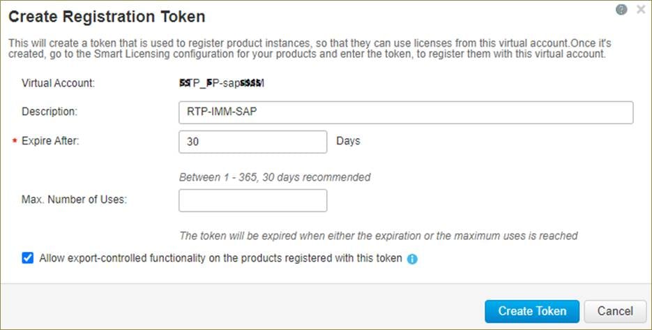
Step 5. In Cisco Intersight click Select Service > System, then click Administration > Licensing.
Step 6. Under Actions, click Register.
Step 7. Enter the copied token from the Cisco Smart Licensing portal. Click Next.
Step 8. Drop-down the pre-selected Default Tier * and select the license type (for example, Advantage for all).
Step 9. Select Move All Servers to Default Tier.
Step 10. Click Register, then click Register again.
Step 11. When the registration is successful (takes a few minutes), the information about the associated Cisco Smart account and default licensing tier selected in the last step is displayed.
Procedure 4. Set Up Cisco Intersight Resource Group
In this procedure, a Cisco Intersight resource group is created where resources such as targets will be logically grouped. In this deployment, a single resource group is created to host all the resources, but customers can choose to create multiple resource groups for granular control of the resources.
Step 1. Log into Cisco Intersight.
Step 2. Select System. Click Settings (the gear icon).
Step 3. Click Resource Groups in the middle panel.
Step 4. Click + Create Resource Group.
Step 5. Provide a name for the Resource Group (for example, AA07-sap-rg).
Step 6. Under Memberships, select Custom.
Step 7. Click Create.
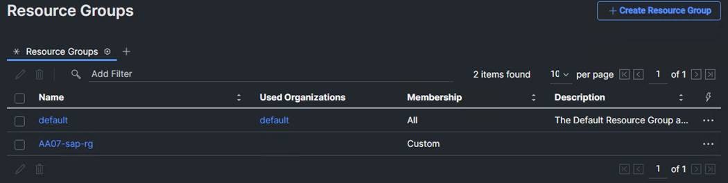
Procedure 5. Set Up Cisco Intersight Organization
In this step, an Intersight organization is created where all Cisco Intersight managed mode configurations including policies are defined.
Step 1. Log into the Cisco Intersight portal.
Step 2. Select System. Click Settings (the gear icon).
Step 3. Click Organizations.
Step 4. Click + Create Organization.
Step 5. Provide a name for the organization (for example, AA07).
Step 6. Select the Resource Group created in the last step (for example, AA07-sap-rg).
Step 7. Click Create.
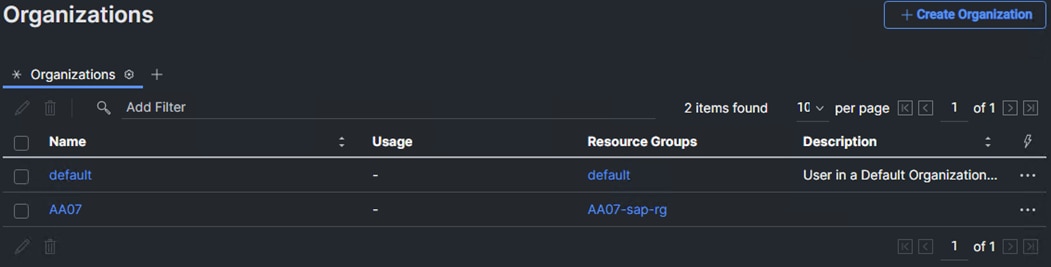
Procedure 6. Claim Cisco UCS Fabric Interconnects in Cisco Intersight
Note: Make sure the initial configuration for the fabric interconnects has been completed. Log into the Fabric Interconnect A Device Console using a web browser to capture the Cisco Intersight connectivity information.
Step 1. Use the management IP address of Fabric Interconnect A to access the device from a web browser and the previously configured admin password to log into the device.
Step 2. Under DEVICE CONNECTOR, the current device status will show “Not claimed.” Note or copy, the Device ID, and Claim Code information for claiming the device in Cisco Intersight.
Step 3. Log into Cisco Intersight.
Step 4. Select System. Click Administration > Targets.
Step 5. Click Claim a New Target.
Step 6. Select Cisco UCS Domain (Intersight Managed) and click Start.
Step 7. Copy and paste the Device ID and Claim from the Cisco UCS FI to Intersight.
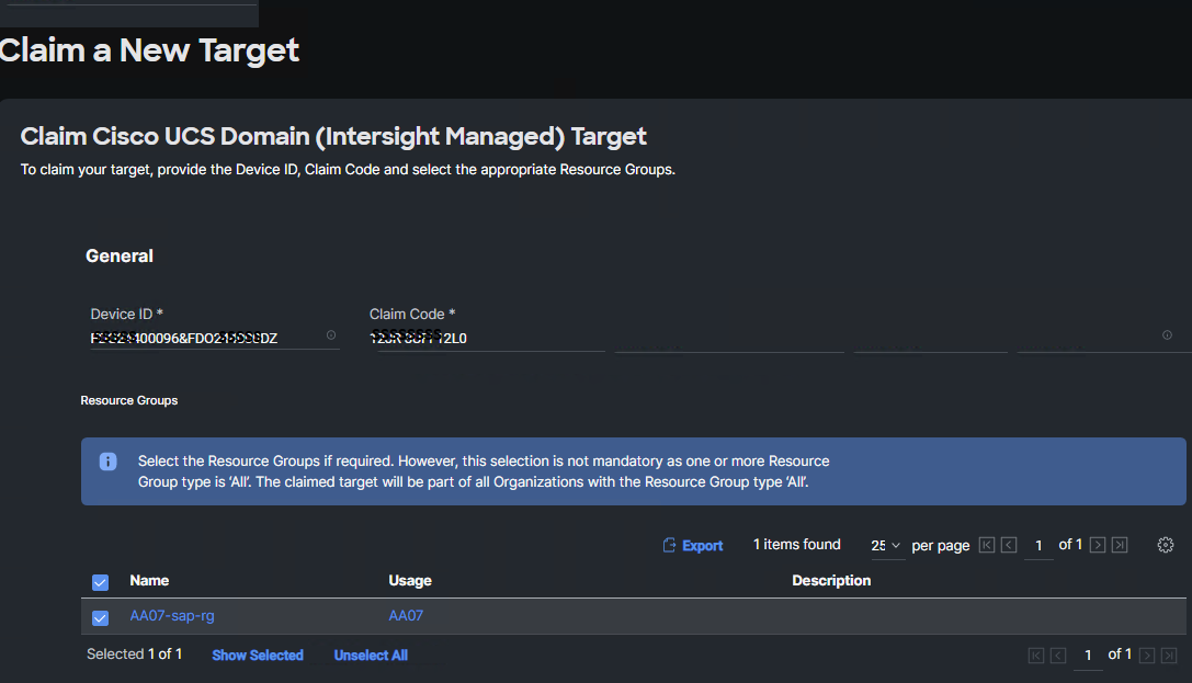
Step 8. Select the previously created Resource Group and click Claim.
With a successful device claim, Cisco UCS FI will appear as a target in Cisco Intersight.
Procedure 7. Verify Addition of Cisco UCS Fabric Interconnects to Cisco Intersight
Step 1. Log into the web GUI of the Cisco UCS Fabric Interconnect and click the browser Refresh button.
The fabric interconnect status should now be set to Claimed.
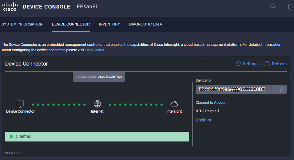
Procedure 8. Upgrade Fabric Interconnect Firmware using Cisco Intersight
Note: If Cisco UCS Fabric Interconnects were upgraded to the latest recommended software using Cisco UCS Manager, this upgrade process through Intersight will still work and will copy the Cisco UCS X-Series firmware to the fabric interconnects.
Step 1. Log into the Cisco Intersight portal.
Step 2. From the drop-down list, select Infrastructure Service and then under Operate, select Fabric Interconnects.
Step 3. Click the ellipses “…” at the end of the row for either of the Fabric Interconnects and select Upgrade Firmware.
Step 4. Click Start.
Step 5. Verify the Fabric Interconnect information and click Next.
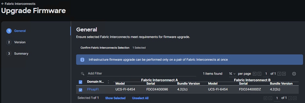
Step 6. Enable Advanced Mode using the toggle switch and uncheck Fabric Interconnect Traffic Evacuation.
Step 7. Select the recommended release from the list and click Next.
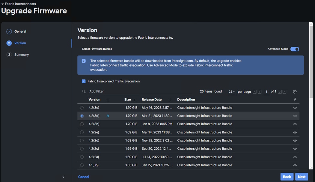
Step 8. Verify the information and click Upgrade to start the upgrade process.
Step 9. View the Request panel of the main Intersight screen since the system will ask for user permission before upgrading each FI. Click the Circle with Arrow and follow the prompts on the screen to grant permission.
Step 10. Wait for both the FIs to successfully upgrade.
Procedure 9. Configure a Cisco UCS Domain Profile
Note: A Cisco UCS domain profile configures a fabric interconnect pair through reusable policies, allows configuration of the ports and port channels, and configures the VLANs and VSANs in the network. It defines the characteristics of and configured ports on fabric interconnects. The domain-related policies can be attached to the profile either at the time of creation or later. One Cisco UCS domain profile can be assigned to one fabric interconnect domain.
Step 1. Log into the Cisco Intersight portal.
Step 2. From the drop-down list, select Infrastructure Service. Under Configure select Profiles.
Step 3. In the main window, select UCS Domain Profiles and click Create UCS Domain Profile.
Step 4. In the Create UCS Domain Profile screen, click Start.
Procedure 10. General Configuration
Step 1. Select the organization from the drop-down list (for example, AA07).
Step 2. Provide a name for the domain profile (for example, AA07-Domain-Profile).
Step 3. Provide an optional Description.
Step 4. Click Next.
Procedure 11. Cisco UCS Domain Assignment
Step 1. Assign the Cisco UCS domain to this new domain profile by clicking Assign Now and selecting the previously added Cisco UCS domain (for example, FPsapFI).
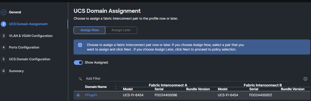
Step 2. Click Next.
In this procedure, a single VLAN policy is created for both fabric interconnects and two individual VSAN policies are created because the VSAN IDs are unique for each fabric interconnect.
Procedure 1. Create and Apply VLAN Policy
Step 1. Click Select Policy under Fabric Interconnect A.
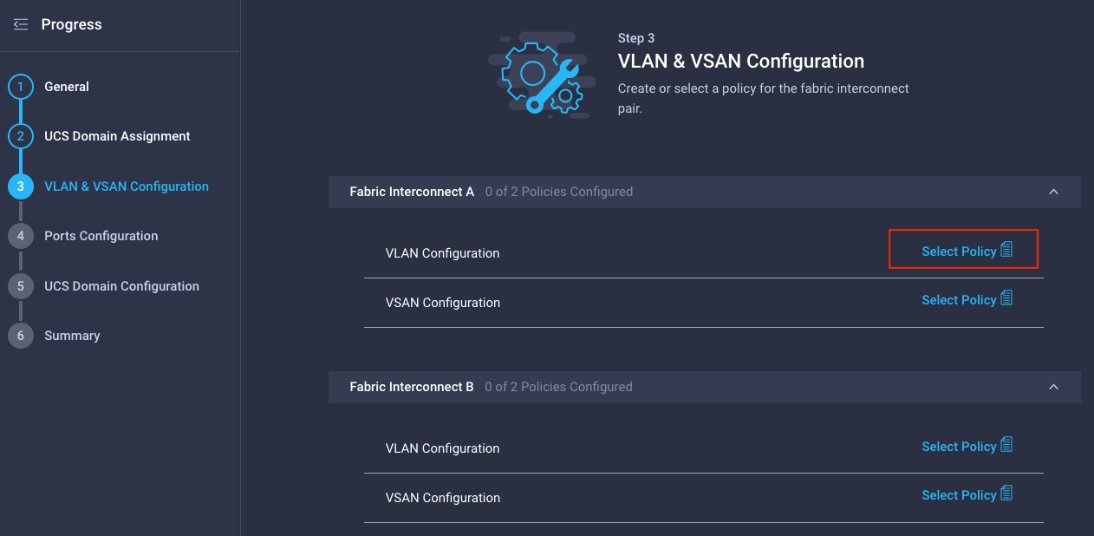
Step 2. Click Create New.
Step 3. Verify the correct organization is selected from the drop-down list (for example, AA07) and provide a name for the policy (for example, AA07-VLAN).
Step 4. Click Next.
Step 5. Click Add VLANs.
Step 6. Provide a name and VLAN ID for the native VLAN.
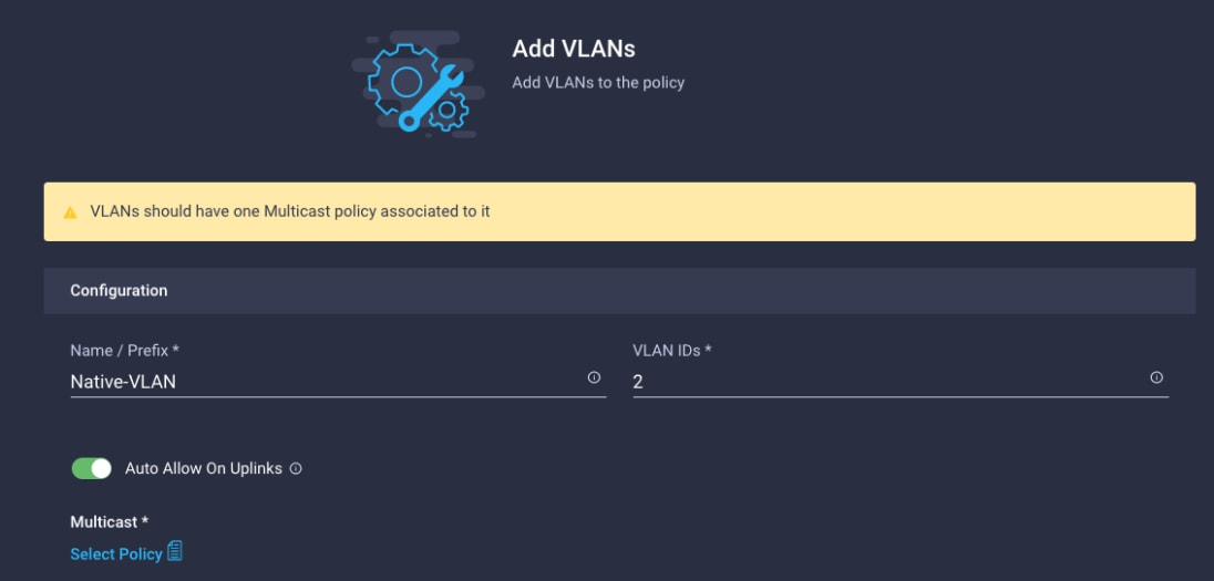
Step 7. Make sure Auto Allow On Uplinks is enabled.
Step 8. To create the required Multicast policy, under Multicast*, click Select Policy.
Step 9. Click Create New to create a new Multicast Policy.
Step 10. Provide a Name for the Multicast Policy (for example, AA07-MCAST).
Step 11. Provide optional Description and click Next.
Step 12. Leave the Snooping State selected and click Create.
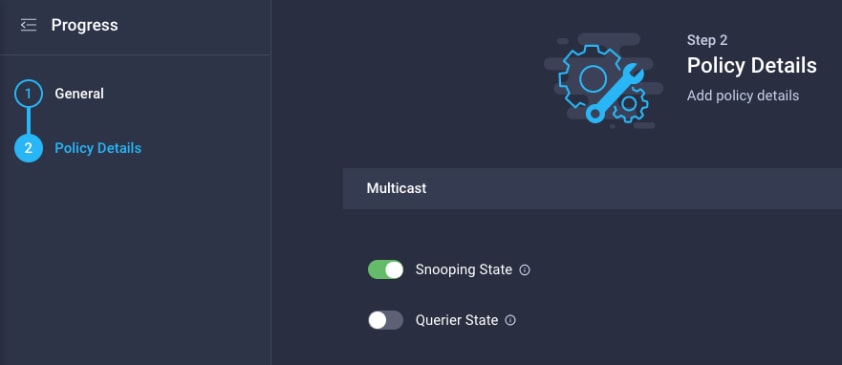
Step 13. Click Add to add the VLAN.
Step 14. Select Set Native VLAN ID and enter the VLAN number (for example, 2) under VLAN ID.
Step 15. Add the remaining VLANs for FlexPod by clicking Add VLANs and entering the VLANs one by one. Reuse the previously created multicast policy for all the VLANs.
The VLANs created during this validation are shown below:
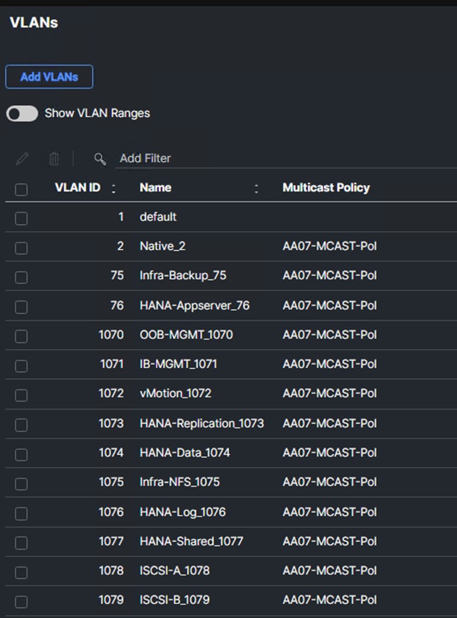
Note: VLANs corresponding to Table 1 are created in this validation setup.
Note: The iSCSI and VLANs shown in the screen image above are only needed when iSCSI is configured in the environment.
Step 16. Click Create to finish creating the VLAN policy and associated VLANs.
Step 17. Click Select Policy next to VLAN Configuration for Fabric Interconnect B and select the same VLAN policy.
Procedure 2. Create and Apply VSAN Policy (FC configuration only)
Step 1. Click Select Policy next to VSAN Configuration under Fabric Interconnect A. Click Create New.
Step 2. Verify the correct organization is selected from the drop-down list (for example, AA07) and provide a name for the policy (for example, AA07-VSAN-Pol-A).
Note: A separate VSAN-Policy is created for each fabric interconnect.
Step 3. Click Next.
Step 4. Enable Uplink Trunking.
Step 5. Click Add VSAN and provide a name (for example, VSAN-A), VSAN ID (for example, 101), and associated Fibre Channel over Ethernet (FCoE) VLAN ID (for example, 101) for SAN A.
Step 6. Set VSAN Scope as Uplink.
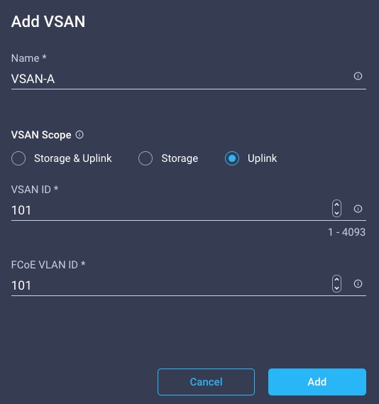
Step 7. Click Add.
Step 8. Click Create to finish creating VSAN policy for fabric A.
Step 9. Repeat the steps to create a new VSAN policy for SAN-B. Name the policy to identify the SAN-B configuration (for example, AA07-VSAN-Pol-B) and use appropriate VSAN and FCoE VLAN (for example, 102).
Step 10. Verify that a common VLAN policy and two unique VSAN policies are associated with the two fabric interconnects.
Step 11. Click Next.
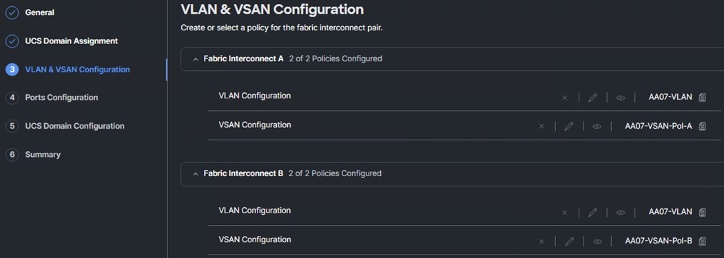
Procedure 3. Ports Configuration
Step 1. Click Select Policy for Fabric Interconnect A.
Step 2. Click Create New to define a new port configuration policy.
Note: Use two separate port policies for the fabric interconnects. Using separate policies provide flexibility when port configuration (port numbers or speed) differs between the two FIs. When configuring Fibre Channel, two port policies are required because each fabric interconnect uses a unique Fibre Channel VSAN ID.
Step 3. Verify correct organization is selected from the drop-down list (for example, AA07) and provide a name for the policy (for example, AA07-PortPol-A).
Step 4. Click Next.
Step 5. Move the slider to set up unified ports. In this deployment, the first four ports were selected as Fibre Channel ports. Click Next.
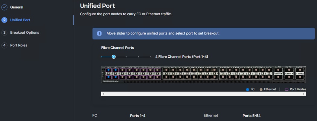
Note: If any Ethernet ports need to be configured as breakouts, either 4x25G or 4x10G, for connecting Cisco UCS C-Series servers or a Cisco UCS 5108 chassis, configure them here. In the list, select the checkbox next to any ports that need to be configured as breakout or select the breakout capable ports on the graphic. When all ports are selected, click Configure at the top of the window. In the Set Breakout popup, select either 4x10G or 4x25G based on the scenario and click Set. Click Next
Step 6. Under the Port Roles list, check the box next to any ports that need to be configured as server ports, including ports connected to chassis or Cisco UCS C-Series servers. Ports can also be selected on the graphic. When all ports are selected, click Configure. Breakout and non-breakout ports cannot be configured together. If you need to configure breakout and non-breakout ports, do this configuration in two steps.
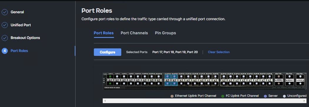
Step 7. From the drop-down list, select Server as the role. Also, unless you are using a Cisco Nexus 93180YC-FX3 as a FEX, leave Auto Negotiation enabled. If you need to do manual number of chassis or Cisco UCS C-Series servers, enable Manual Chassis/Server Numbering.
Step 8. Click Save.
Step 9. Configure the Ethernet uplink port channel by selecting Port Channel in the main pane and then clicking Create Port Channel.
Step 10. Select Ethernet Uplink Port Channel as the role, provide a port-channel ID (for example, 11), and select a value for Admin Speed from drop-down list (for example, Auto).
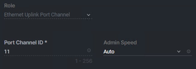
Note: You can create the Ethernet Network Group, Flow Control, Link Aggregation for defining disjoint Layer-2 domain or fine tune port-channel parameters. These policies were not used in this deployment and system default values were utilized.
Step 11. Under Link Control, click Select Policy. Click Create New.
Step 12. Verify the correct organization is selected from the drop-down list (for example, AA07) and provide a name for the policy (for example, AA07-UDLD-Link-Control). Click Next.
Step 13. Leave the default values selected and click Create.
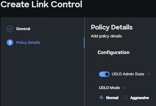
Step 14. Scroll down and select uplink ports from the list of available ports (for example, port 49 and 50)
Step 15. Click Save.
Procedure 4. Configure FC Port Channel (FC configuration only)
Note: An FC uplink port channels only needed when configuring FC SAN and can be skipped for IP-only (iSCSI) storage access.
Step 1. Configure a Fibre Channel Port Channel by selecting the Port Channel in the main pane again and clicking Create Port Channel.
Step 2. In the drop-down list under Role, select FC Uplink Port Channel.
Step 3. Provide a port-channel ID (for example, 21), select a value for Admin Speed (for example, 32Gbps), and provide a VSAN ID (for example, 101).
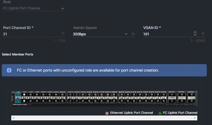
Step 4. Select ports (for example, 1 and 2).
Step 5. Click Save.
Step 6. Verify the port-channel IDs and ports after both the Ethernet uplink port channel and the Fibre Channel uplink port channel have been created.
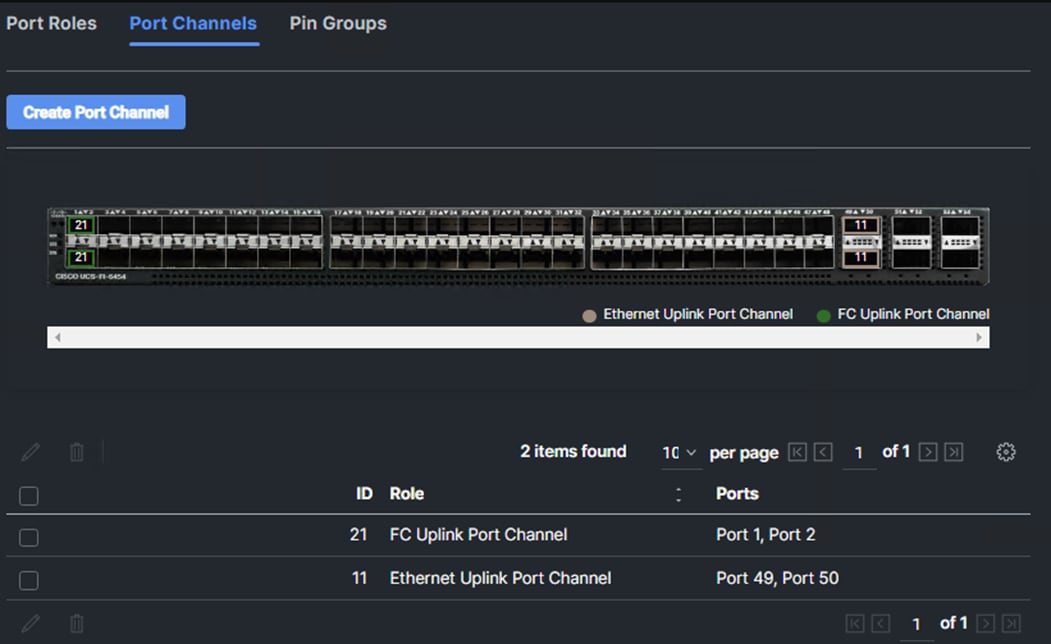
Step 7. Click Save to create the port policy for Fabric Interconnect A.
Note: Use the summary screen to verify that the ports were selected and configured correctly.
Procedure 5. Port Configuration for Fabric Interconnect B
Step 1. Repeat the steps in Ports Configuration and Configure FC Port Channel to create the port policy for Fabric Interconnect B including the Ethernet port-channel and the FC port-channel (if configuring SAN). Use the following values for various parameters:
● Name of the port policy: AA07-PortPol-B
● Ethernet port-Channel ID: 12
● FC port-channel ID: 22
● FC VSAN ID: 102
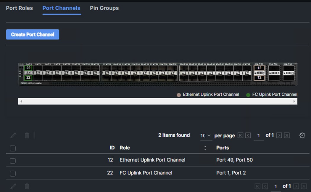
Step 2. When the port configuration for both fabric interconnects is complete and looks good, click Next.
Procedure 6. UCS Domain Configuration
Under UCS domain configuration, additional policies can be configured to setup NTP, Syslog, DNS settings, SNMP, QoS and UCS operating mode (end host or switch mode). For this deployment, four policies (NTP, Network Connectivity, SNMP, and System QoS) will be configured, as shown below:
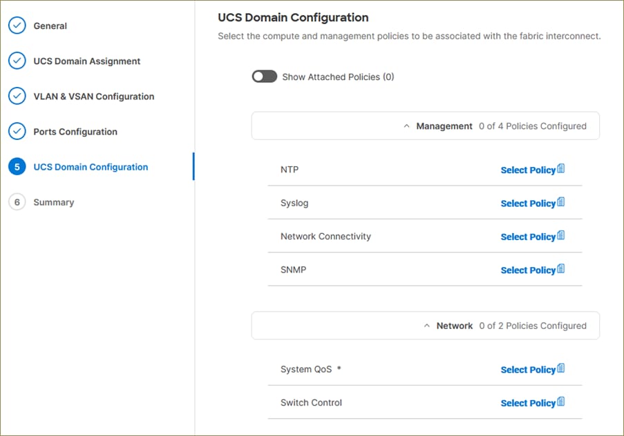
Procedure 7. Configure NTP Policy
Step 1. Click Select Policy next to NTP and click Create New.
Step 2. Verify correct organization is selected from the drop-down list (for example, AA07) and provide a name for the policy (for example, AA07-NTP).
Step 3. Click Next.
Step 4. Enable NTP, provide the first NTP server IP address, and select the time zone from the drop-down list.
Step 5. Add a second NTP server by clicking + next to the first NTP server IP address.
Note: The NTP server IP addresses should be Nexus switch management IPs. NTP distribution was configured in the Cisco Nexus switches.
Step 6. Click Create.
Procedure 8. Configure Network Connectivity Policy
Step 1. Click Select Policy next to Network Connectivity and click Create New.
Step 2. Verify correct organization is selected from the drop-down list (for example, AA07) and provide a name for the policy (for example, AA07-NetConn).
Step 3. Click Next.
Step 4. Provide DNS server IP addresses for Cisco UCS.
Step 5. Click Create.
Procedure 9. Configure SNMP Policy
Step 1. Click Select Policy next to SNMP and click Create New.
Step 2. Verify correct organization is selected from the drop-down list (for example, AA07) and provide a name for the policy (for example, AA07-SNMP).
Step 3. Click Next.
Step 4. Provide a System Contact email address, a System Location, and optional Community Strings.
Step 5. Under SNMP Users, click Add SNMP User.
Step 6. This user id will be used for Cisco DCNM SAN to query the Cisco UCS Fabric Interconnects. Fill in a user name (for example, snmpadmin), Auth Type SHA, an Auth Password with confirmation, Privacy Type AES, and a Privacy Password with confirmation. Click Add.
Step 7. Optionally, add an SNMP Trap Destination (for example, the DCNM SAN IP Address). If the SNMP Trap Destination is V2, you must add Trap Community String.
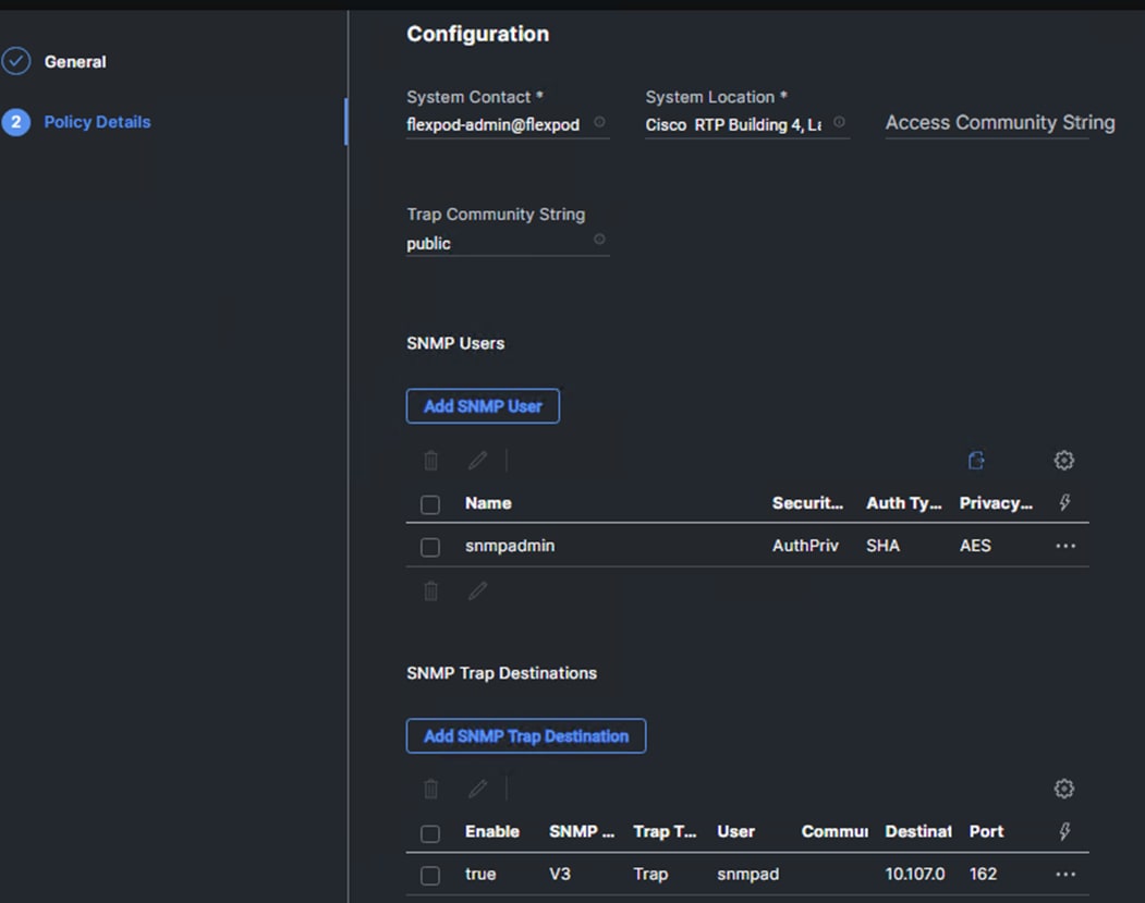
Step 8. Click Create.
Procedure 10. Configure System QoS Policy
Step 1. Click Select Policy next to System QoS* and click Create New.
Step 2. Verify correct organization is selected from the drop-down list (for example, AA07) and provide a name for the policy (for example, AA07-QoSPol).
Step 3. Click Next.
Step 4. Change the MTU for Best Effort class to 9216.
Step 5. Keep the default selections or change the parameters if necessary.
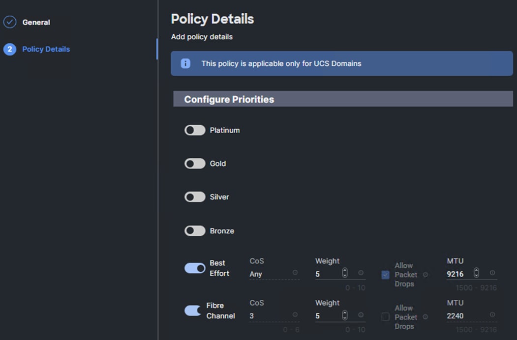
Step 6. Click Create.
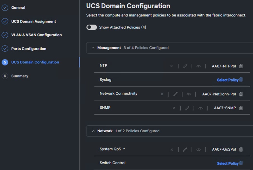
Step 7. Click Next.
Step 1. Verify all the settings including the fabric interconnect settings, by expanding the settings and make sure that the configuration is correct.
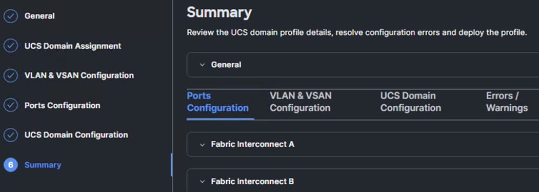
Procedure 12. Deploy the Cisco UCS Domain Profile
Step 1. From the UCS domain profile Summary view, Click Deploy.
Step 2. Acknowledge any warnings and click Deploy again.
Note: The system will take some time to validate and configure the settings on the fabric interconnects. Log into the console servers to see when the Cisco UCS fabric interconnects have finished configuration and are successfully rebooted.
Procedure 13. Verify Cisco UCS Domain Profile Deployment
When the Cisco UCS domain profile has been successfully deployed, the Cisco UCS chassis and the blades should be successfully discovered.
Note: It takes a while to discover the blades for the first time. Watch the number of outstanding requests in Cisco Intersight:
Step 1. Log into Cisco Intersight. Under Infrastructure Service > Configure > Profiles > UCS Domain Profiles, verify that the domain profile has been successfully deployed.
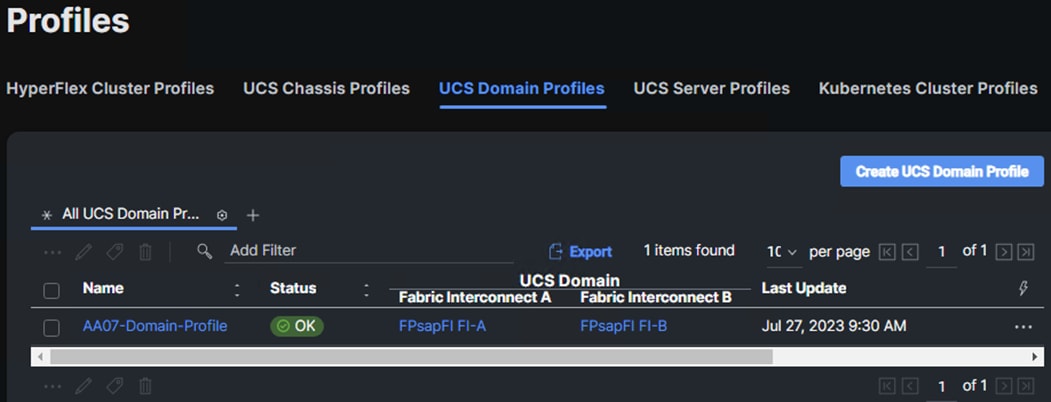
Step 2. Verify that the chassis (either UCSX-9508 or UCS 5108 chassis) has been discovered and is visible under Infrastructure Service > Operate > Chassis.
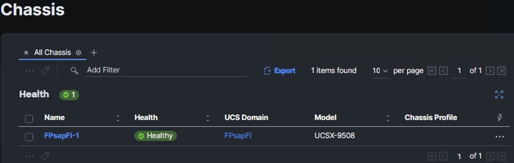
Step 3. Verify that the servers have been successfully discovered and are visible under Infrastructure Service > Operate > Servers.
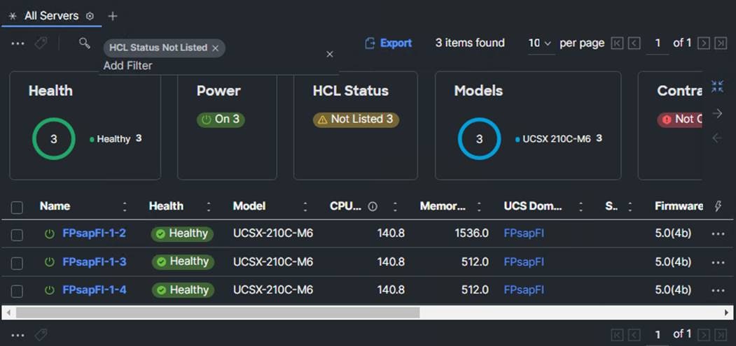
Cisco UCS IMM Manual Configuration
Configure Cisco UCS Chassis Profile
The Cisco UCS Chassis profile in Cisco Intersight allows you to configure various parameters for chassis, including:
● IMC Access Policy: IP configuration for the in-band chassis connectivity. This setting is independent of Server IP connectivity and only applies to communication to and from chassis.
● SNMP Policy, and SNMP trap settings.
● Power Policy to enable power management and power supply redundancy mode.
● Thermal Policy to control the speed of FANs
A chassis policy can be assigned to any number of chassis profiles to provide a configuration baseline for a chassis. In this deployment, a chassis profile with Power and Thermal policies was created and deployed to the chassis.
Procedure 1. Configure Power Policy
Step 1. To configure the Power Policy for the Cisco UCS Chassis profile, go to Infrastructure Service > Configure > Polices > and click Create Policy.
Step 2. Select the platform type UCS Chassis and select Power.
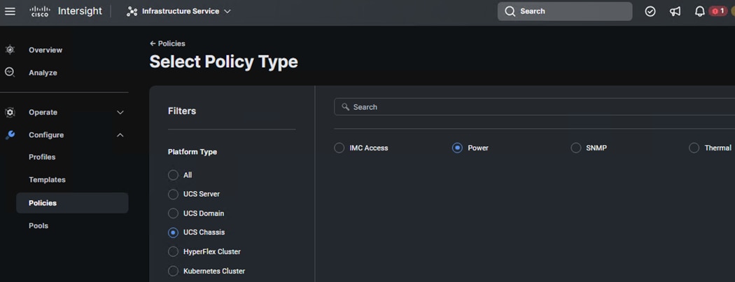
Step 3. In the Power Policy Create section, for Organization select AA07 and enter the Policy name AA07-Chassis-Power and click Next.
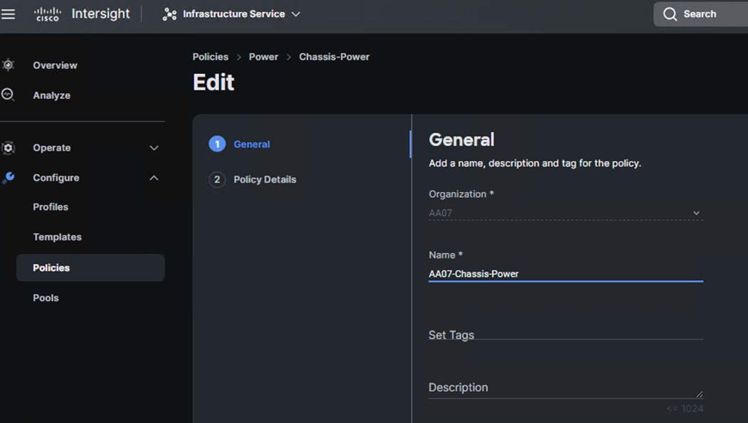
Step 4. In the Policy Details section, for Power Redundancy select N+1 and turn off Power Save Mode.
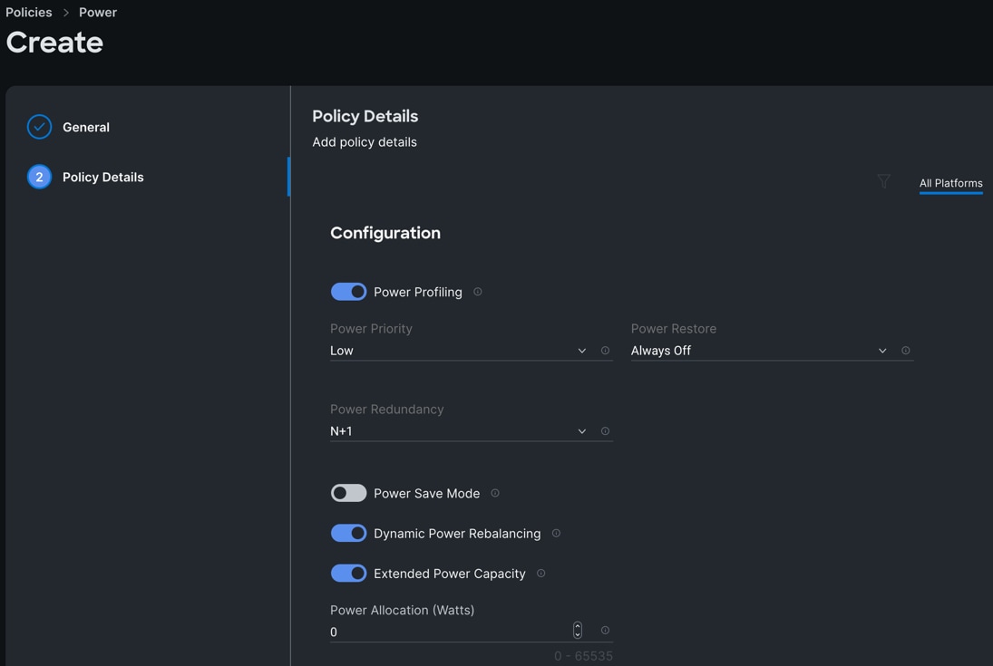
Step 5. Click Create to create this policy.
Procedure 2. Configure Thermal Policy
Step 1. To configure the Thermal Policy for the Cisco UCS Chassis profile, go to Infrastructure Service > Configure > Polices > and click Create Policy.
Step 2. For the platform type select UCS Chassis and select Thermal.
Step 3. In the Power Policy Create section, for Organization select “AA07” and enter the Policy name “AA07-Chassis-Thermal” and click Next.
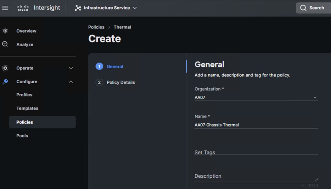
Step 4. In the Policy Details section, for Fan Control Mode select High Power.
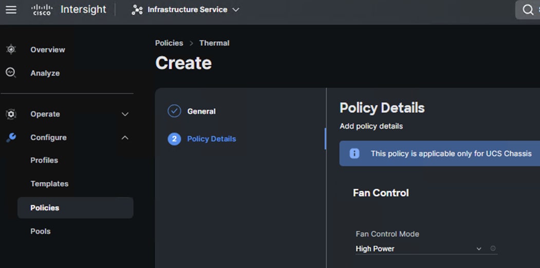
Step 5. Click Create to create this policy.
Procedure 3. Create Cisco UCS Chassis Profile
A Cisco UCS Chassis profile enables you to create and associate chassis policies to an Intersight Managed Mode (IMM) claimed chassis. When a chassis profile is associated with a chassis, Cisco Intersight automatically configures the chassis to match the configurations specified in the policies of the chassis profile. The chassis-related policies can be attached to the profile either at the time of creation or later. Please refer to this link for more details: https://intersight.com/help/saas/features/chassis/configure#chassis_profiles.
The chassis profile in a FlexPod is used to set the power policy for the chassis. By default, UCSX power supplies are configured in GRID mode, but the power policy can be utilized to set the power supplies in preferable N+1 redundant mode and correspondingly set the desired Fan Control mode.
Step 1. To create a Cisco UCS Chassis Profile, go to Infrastructure Service > Configure > Profiles > UCS Chassis Domain Profiles tab > and click Create UCS Chassis Profile.
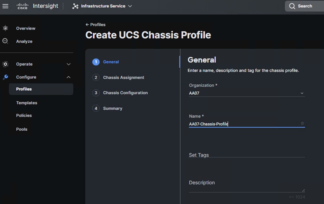
Step 2. In the Chassis Assignment menu, for the first chassis, select the listed chassis and click Next.
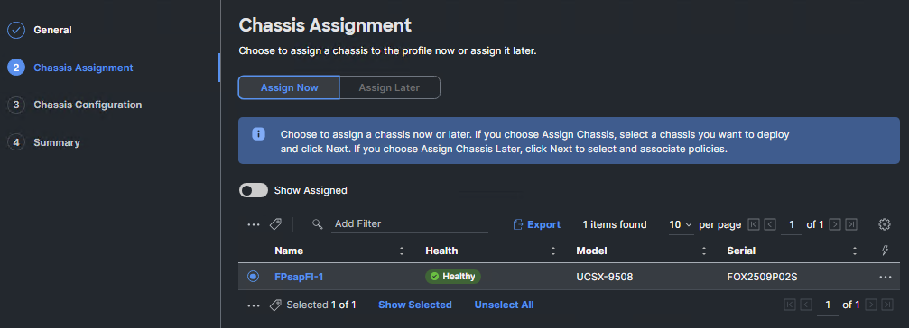
Step 3. In the Chassis configuration section, for the Power and Thermal, select the previously created policies.
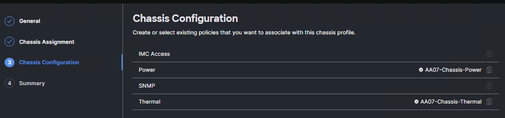
Step 4. Review the configuration settings summary for the Chassis Profile and click Deploy to create the Cisco UCS Chassis Profile for the chassis.
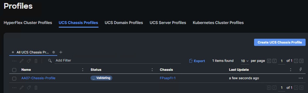
Configure Server Profile Template
In the Cisco Intersight platform, a server profile enables resource management by simplifying policy alignment and server configuration. The server profiles are derived from a server profile template. A Server profile template and its associated policies can be created using the server profile template wizard. After creating server profile template, customers can derive multiple consistent server profiles from the template.
The server profile templates captured in this deployment guide supports Cisco UCS X210c M6 with 4th Generation VICs.
vNIC and vHBA Placement for Server Profile Template
In this deployment guide, separate server profile templates are created for iSCSI connected storage and for FC connected storage. Further differentiation is made based on the SAP HANA implementation type – bare-metal or virtualized.
Note: While the SAP HANA specific networks are handled by creating respective port groups in the virtualized implementation at the time of vCenter networking configuration, you will need to create all the required vNICs now to account for application traffic like SAP Application server connect network, SAP HANA system backup network, SAP HANA system Replication network and the like, in case of bare-metal installation.
The vNIC and vHBA layout for all permutations is covered below. While most of the policies are common across various templates, the LAN connectivity and SAN connectivity policies are unique and will use the information in the tables below.
Six vNICs are configured to support iSCSI boot from SAN for virtualized SAP HANA scaleup system. Eight vNICs example for bare-metal system is provided. These vNICs are manually placed as listed in Table 6.and Table 7.
Table 6. vNIC placement for iSCSI connected storage for virtualized SAP HANA Scale-up system
| vNIC Name |
Switch ID |
PCI Order |
| 01-vSwitch0-A |
A |
0 |
| 02-vSwitch0-B |
B |
1 |
| 03-VDS0-A |
A |
2 |
| 04-VDS0-B |
B |
3 |
| 05-ISCSI-A |
A |
4 |
| 06-ISCSI-B |
B |
5 |
Table 7. vNIC placement for iSCSI connected storage for bare-metal SAP HANA Scale-up system
| vNIC Name |
Switch ID |
PCI Order |
| 01-HANA-Admin |
A |
0 |
| 02-HANA-Appserver |
A |
1 |
| 03-HANA-Replication |
B |
2 |
| 04-HANA-Shared |
B |
3 |
| 05-ISCSI-A |
A |
4 |
| 06-ISCSI-B |
B |
5 |
| 07-HANA-Data |
A |
6 |
| 08-HANA-Log |
B |
7 |
Similarly, for FC based setup, four vNICs each in either virtualized or bare-metal examples with two vHBAs that enable support to FC boot from SAN is provided below. Two vHBAs (FCP-Fabric-A and FCP-Fabric-B) are used for boot from SAN connectivity. These devices are manually placed as listed in Table 8 and Table 9
Table 8. vHBA and vNIC placement for FC connected storage for virtualized SAP HANA Scale-up system
| vNIC/vHBA Name |
Switch ID |
PCI Order |
| FCP-Fabric-A |
A |
0 |
| FCP-Fabric-B |
B |
1 |
| 01-vSwitch0-A |
A |
2 |
| 02-vSwitch0-B |
B |
3 |
| 03-VDS0-A |
A |
4 |
| 04-VDS0-B |
B |
5 |
Table 9. vHBA and vNIC placement for FC connected storage for bare-metal SAP HANA Scale-up system
| Switch ID |
PCI Order |
|
| FCP-Fabric-A |
A |
0 |
| FCP-Fabric-B |
B |
1 |
| 01-HANA-Admin |
A |
2 |
| 02-HANA-Shared |
B |
3 |
| 03-HANA-Appserver |
A |
4 |
| 04-HANA-Replication |
B |
5 |
Procedure 1. Server Profile Template Creation
Step 1. Log into Cisco Intersight.
Step 2. Go to Infrastructure Service > Configure > Templates and click Create UCS Server Profile Template.
Procedure 2. General Configuration
Step 1. Select the organization from the drop-down list (for example, AA07).
Step 2. Provide a name for the server profile template. The names used in this part of the deployment are:
◦ ISCSI-Boot-Template (iSCSI boot from SAN)
◦ FC-Boot-Template (FC boot from SAN)
Step 3. Select UCS Server (FI-Attached).
Step 4. Provide an optional description.
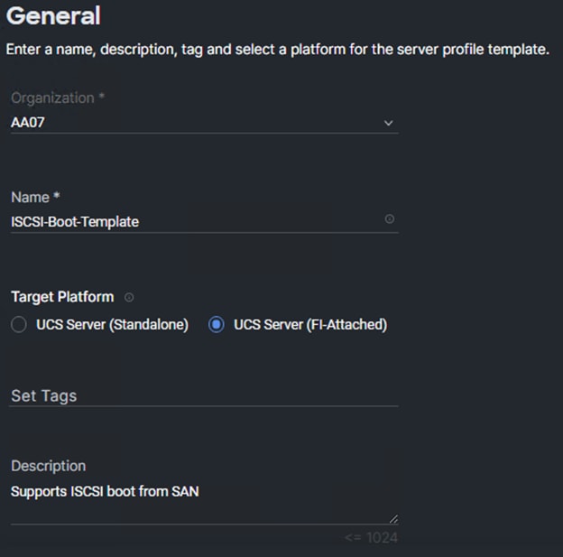
Step 5. Click Next.
Procedure 3. Compute Configuration – Configure UUID Pool
Step 1. Click Select Pool under UUID Pool and click Create New.
Step 2. Verify correct organization is selected from the drop-down list (for example, AA07) and provide a name for the UUID Pool (for example, AA07-UUID-Pool).
Step 3. Provide an optional Description and click Next.
Step 4. Provide a UUID Prefix (for example, a prefix of AA070000-0000-0001 was used).
Step 5. Add a UUID block.
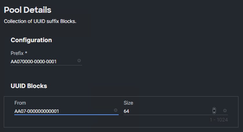
Step 6. Click Create.
Procedure 4. Configure BIOS Policy
Step 1. Click Select Policy next to BIOS and click Create New.
Step 2. Verify correct organization is selected from the drop-down list (for example, AA07) and provide a name for the policy for example, AA07-HANA-BIOS for bare-metal system and AA07-vHANA-BIOS for ESXi nodes hosting virtualized SAP HANA system.
Step 3. Click Next.
Step 4. On the Policy Details screen, select appropriate values for the BIOS settings. In this deployment, the BIOS values were selected based on recommendations in the performance tuning guide for Cisco UCS M6 BIOS: https://www.cisco.com/c/en/us/products/collateral/servers-unified-computing/ucs-b-series-blade-servers/performance-tuning-guide-ucs-m6-servers.html. Set the parameters as listed in the following tables and leave all other parameters set to “platform-default.”
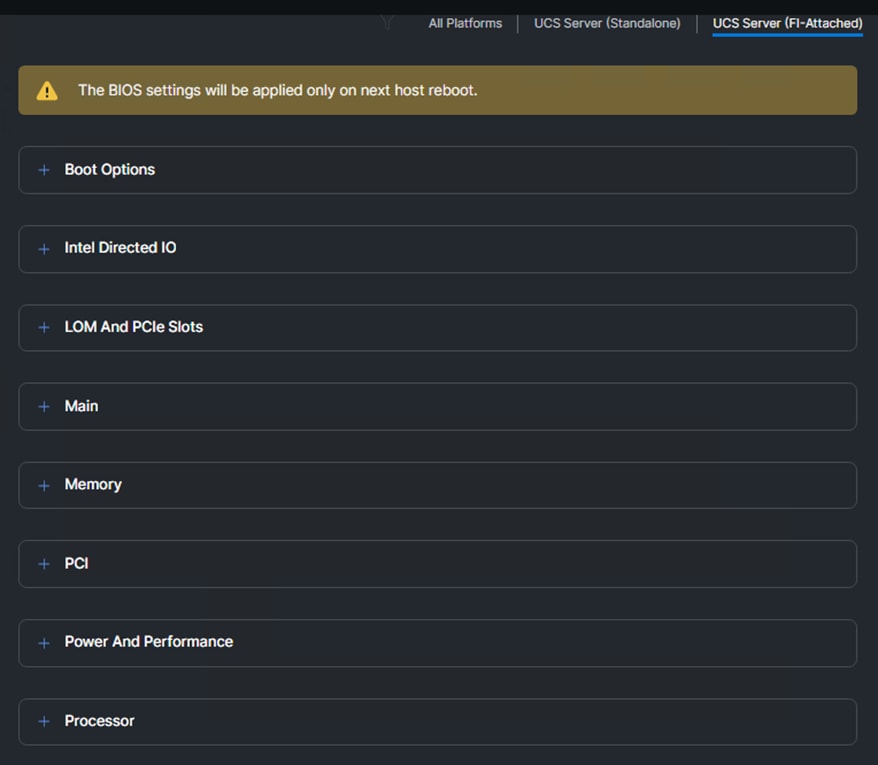
Table 10. vHBA and vNIC placement for FC connected storage for virtualized SAP HANA Scale-up system
| BIOS Tokens |
BIOS Values (platform default) |
Recommended Value |
| CPU performance |
Custom |
Enterprise |
| Enhanced CPU Performance |
Disabled |
Auto |
Table 11. vHBA and vNIC placement for FC connected storage for bare-metal SAP HANA Scale-up system
| BIOS Tokens |
BIOS Values (platform default) |
Recommended Value |
| Intel Virtualization Technology |
Enabled |
Disabled |
| Intel VT for Directed I/O |
Enabled |
Disabled |
| CPU performance |
Custom |
Enterprise |
| Enhanced CPU Performance |
Disabled |
Auto |
Note: The platform default setting for most of the BIOS tokens under Processor, Power and Performance and Memory section is in line with SAP HANA requirements relating to Processor C-States and performance tuning except for those mentioned above.
Procedure 5. Configure Boot Order Policy for iSCSI Hosts
Note: The FC boot order policy is different from iSCSI boot policy and is explained next.
Step 1. Click Select Policy next to Boot Order and then, click Create New.
Step 2. Verify correct organization is selected from the drop-down list (for example, AA07) and provide a name for the policy (for example, AA07-iSCSI-BootOrder-Pol).
Step 3. Click Next.
Step 4. For Configured Boot Mode, select Unified Extensible Firmware Interface (UEFI).
Step 5. Turn on Enable Secure Boot.
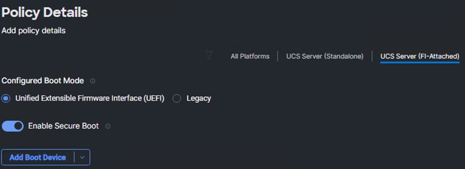
Step 6. Click Add Boot Device drop-down list and select Virtual Media.
Step 7. Provide a device name (for example, Virtual Media-ISO) and then, for the subtype, select KVM Mapped DVD.
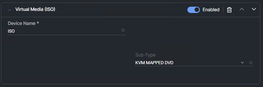
Step 8. From the Add Boot Device drop-down list, select iSCSI Boot.
Step 9. Provide the Device Name: iSCSI-A-Boot and the exact name of the interface used for iSCSI boot under Interface Name: 04-iSCSI-A.
Note: The device names (iSCSI-A-Boot and iSCSI-B-Boot) are being defined here and will be used in the later steps of the iSCSI configuration.
Step 10. From the Add Boot Device drop-down list, select iSCSI Boot.
Step 11. Provide the Device Name: iSCSI-B-Boot and the exact name of the interface used for iSCSI boot under Interface Name: 05-iSCSI-B.
Step 12. From the Add Boot Device drop-down list, select UEFIShell.
Step 13. Add Device Name UEFIShell and select the subtype UEFIShell.
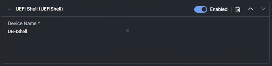
Step 14. Verify the order of the boot policies and adjust the boot order as necessary using arrows next to the Delete button.
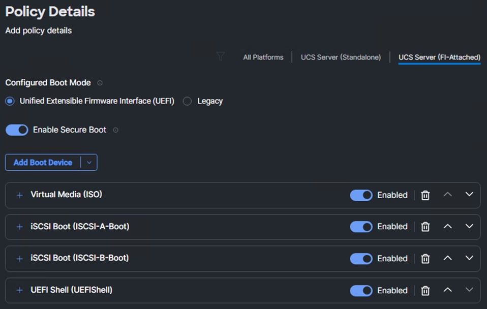
Step 15. Click Create.
Procedure 6. Configure Boot Order Policy for FC Hosts
Note: The FC boot order policy applies to all FC hosts including hosts that support FC storage access.
Step 1. Click Select Policy next to Boot Order and click Create New.
Step 2. Verify correct organization is selected from the drop-down list (for example, AA07) and provide a name for the policy (for example, AA07-FC-BootOrder-Pol).
Step 3. Click Next.
Step 4. For Configured Boot Mode, select Unified Extensible Firmware Interface (UEFI).
Step 5. Turn on Enable Secure Boot.
Step 6. Click Add Boot Device drop-down list and select Virtual Media.
Step 7. Provide a device name (for example, KVM-Mapped-ISO) and then, for the subtype, select KVM Mapped DVD.
For Fibre Channel SAN boot, all four NetApp controller FCP LIFs will be added as boot options. The four LIFs are named as follows:
● fcp-lif-01a: NetApp Controller 1, LIF for Fibre Channel SAN A
● fcp-lif-01b: NetApp Controller 1, LIF for Fibre Channel SAN B
● fcp-lif-02a: NetApp Controller 2, LIF for Fibre Channel SAN A
● fcp-lif-02b: NetApp Controller 2, LIF for Fibre Channel SAN B
Step 8. From the Add Boot Device drop-down list, select SAN Boot.
Step 9. Provide the Device Name: fcp-lif-01a and the Logical Unit Number (LUN) value (for example, 0).
Step 10. Provide an interface name FCP-Fabric-A. This value is important and should match the vHBA name.
Note: FCP-Fabric-A is used to access fcp-lif-01a and fcp-lif-02a and FCP-Fabric-B is used to access fcp-lif-01b and fcp-lif-02b.
Step 11. Add the appropriate World Wide Port Name (WWPN) as the Target WWPN.
Note: To obtain the WWPN values, log into NetApp controller using SSH and enter the following command: network interface show -vserver AA07-Infra-SVM -data-protocol fcp
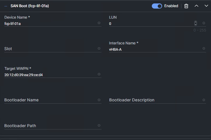
Step 12. Repeat steps 8-11 three more times to add all the NetApp LIFs.
Step 13. From the Add Boot Device drop-down list, select UEFIShell.
Step 14. Add Device Name UEFIShell and select the subtype UEFIShell.
Step 15. Verify the order of the boot policies and adjust the boot order as necessary using arrows next to the Delete button.
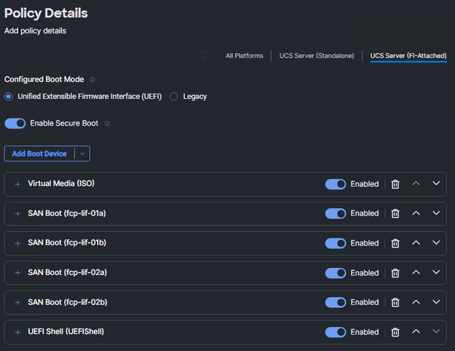
Step 16. Click Create.
Step 17. Make sure the correct Boot Order policy is selected. If not, select the correct policy.
Procedure 7. Configure Virtual Media Policy
Step 1. Click Select Policy next to Virtual Media and click Create New.
Step 2. Verify correct organization is selected from the drop-down list (for example, AA07) and provide a name for the policy (for example, AA07-vMedia-Pol).
Step 3. Turn on Enable Virtual Media, Enable Virtual Media Encryption, and Enable Low Power USB.
Step 4. Do not Add Virtual Media at this time, but the policy can be modified and used to map and ISO for a CIMC Mapped DVD.
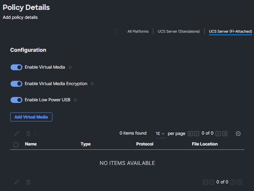
Step 5. Click Create.
Step 6. Click Next to move to Management Configuration.
The following policies will be added to the management configuration:
● IMC Access to define the pool of IP addresses for compute node KVM access
● IPMI Over LAN to allow Intersight to manage IPMI messages
● Local User to provide local administrator to access KVM
● Virtual KVM to allow the Tunneled KVM
Procedure 1. Configure Cisco IMC Access Policy
Step 1. Click Select Policy next to IMC Access and click Create New.
Step 2. Verify correct organization is selected from the drop-down list (for example, AA07) and provide a name for the policy (for example, AA07-IMC-Access).
Step 3. Click Next.
Note: You can select in-band management access to the compute node using an in-band management VLAN (for example, VLAN 1071) or out-of-band management access via the Mgmt0 interfaces of the FIs. KVM Policies like SNMP, vMedia and Syslog are currently not supported via Out-Of-Band and will require an In-Band IP to be configured.
Step 4. Click UCS Server (FI-Attached).
Step 5. Enable In-Band Configuration. Enter the IB-MGMT VLAN ID (for example, 1011) and select IPv4 address configuration.
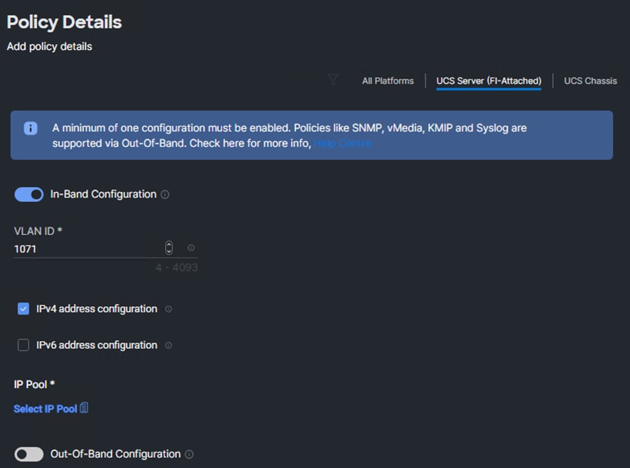
Step 6. Under IP Pool, click Select IP Pool and click Create New.
Step 7. Verify the correct organization is selected from the drop-down list (for example, AA07) and provide a name for the policy (for example, AA07-IB-MGMT-IP-Pool).
Step 8. Select Configure IPv4 Pool and provide the information to define a pool for KVM IP address assignment including an IP Block.
Note: The management IP pool subnet should be accessible from the host that is trying to open the KVM connection. In the example shown here, the hosts trying to open a KVM connection would need to be able to route to the 10.107.1.0/24 subnet.
Step 9. Click Next.
Step 10. Deselect Configure IPv6 Pool.
Step 11. Click Create to finish configuring the IP address pool.
Step 12. Click Create to finish configuring the IMC access policy.
Procedure 2. Configure IPMI Over LAN Policy
Step 1. Click Select Policy next to IPMI Over LAN and click Create New.
Step 2. Verify the correct organization is selected from the drop-down list (for example, AA07) and provide a name for the policy (for example, AA07-Enable-IPMIoLAN-Policy).
Step 3. On the right, select UCS Server (FI-Attached)
Step 4. Turn on Enable IPMI Over LAN.
Step 5. From the Privilege Level drop-down list, select admin.
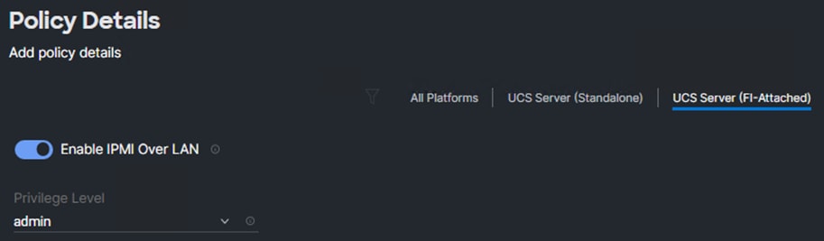
Step 6. Click Create.
Procedure 3. Configure Local User Policy
Step 1. Click Select Policy next to Local User and click Create New.
Step 2. Verify correct organization is selected from the drop-down list (for example, AA07) and provide a name for the policy (for example, AA07-LocalUser-Pol).
Step 3. Verify that UCS Server (FI-Attached) is selected.
Step 4. Verify that Enforce Strong Password is selected.
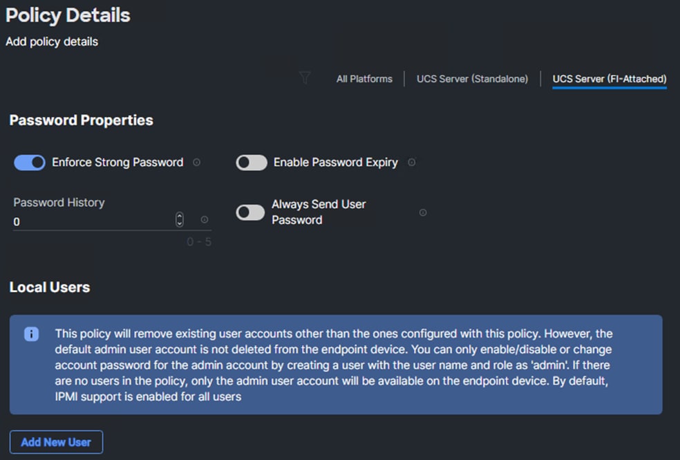
Step 5. Click Add New User and then click + next to the New User
Step 6. Provide the username (for example, admin), select a role for example, admin), and provide a password.
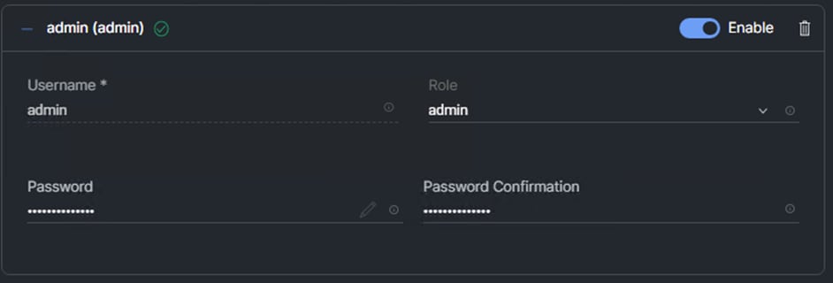
Note: The username and password combination defined here will be used as an alternate to log in to KVMs and can be used for IPMI.
Step 7. Click Create to finish configuring the user.
Step 8. Click Create to finish configuring local user policy.
Procedure 4. Configure Virtual KVM Policy
Step 1. Click Select Policy next to Virtual KVM and click Create New.
Step 2. Verify correct organization is selected from the drop-down list (for example, AA07) and provide a name for the policy (for example, AA07-KVM-Policy).
Step 3. Verify that UCS Server (FI-Attached) is selected.
Step 4. Turn on Allow Tunneled vKVM.
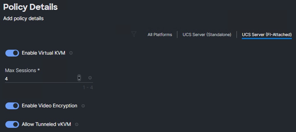
Step 5. Click Create.
Note: To fully enable Tunneled KVM, once the Server Profile Template has been created, go to System > Settings > Security and Privacy and click Configure. Turn on Allow Tunneled vKVM Launch and Allow Tunneled vKVM Configuration.
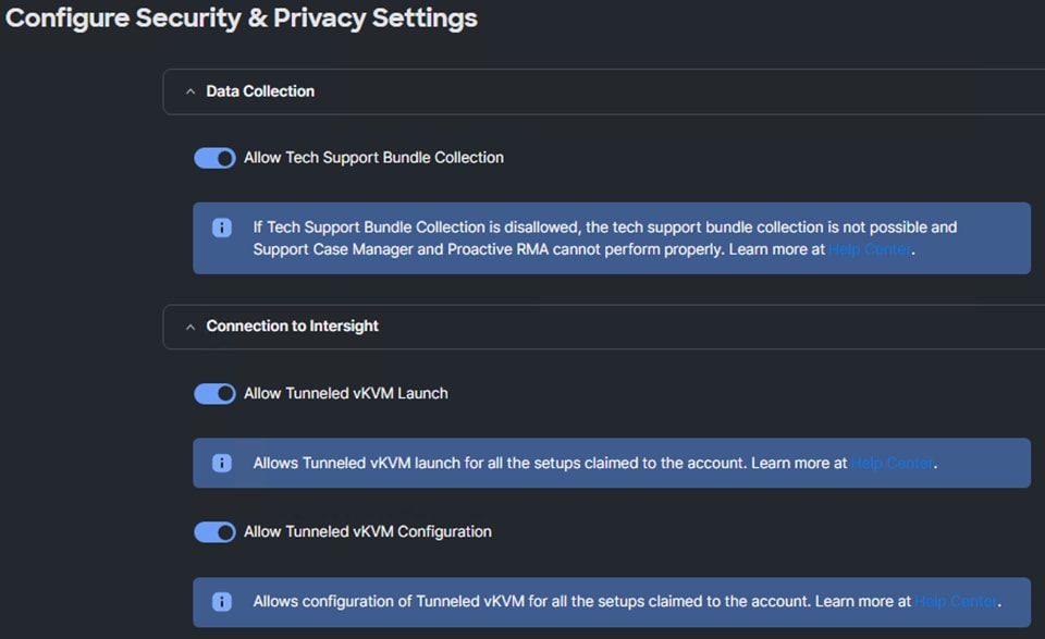
Step 6. Click Next to go to the Storage Configuration procedure.
Procedure 5. Storage Configuration
Step 1. Click Next on the Storage Configuration screen. No configuration is needed in the local storage system.
Procedure 6. Create Network Configuration - LAN Connectivity
The LAN connectivity policy defines the connections and network communication resources between the server and the LAN. This policy uses pools to assign MAC addresses to servers and to identify the vNICs that the servers use to communicate with the network. For iSCSI hosts, this policy also defines an IQN address pool.
For consistent vNIC and vHBA placement, manual vHBA/vNIC placement is utilized. Additionally, the assumption is being made here that each server contains only one VIC card. And that Simple placement, which adds vNICs to the first VIC, is being used. If you have more than one VIC in a server, the Advanced placement will need to be used.
ISCSI boot from SAN hosts and FC boot from SAN hosts require different numbers of vNICs/vHBAs and different placement order therefore the iSCSI host and the FC host LAN connectivity policies are explained separately in this section. If only configuring FC-booted hosts, skip to Procedure 14.
The iSCSI boot from SAN hosts uses 6 vNICs configured as listed in Table 12 and Table 13 in virtualized and bare-metal use-cases.
Table 12. vNIC placement for iSCSI connected storage for virtualized SAP HANA Scale-up system
| vNIC/vHBA Name |
Switch ID |
PCI Order |
| 01-vSwitch0-A |
A |
0 |
| 02-vSwitch0-B |
B |
1 |
| 03-VDS0-A |
A |
2 |
| 04-VDS0-B |
B |
3 |
| 05-ISCSI-A |
A |
4 |
| 06-ISCSI-B |
B |
5 |
Table 13. vNICs for iSCSI LAN Connectivity - bare-metal Scale-Up HANA system example
| vNIC/vHBA Name |
Switch ID |
PCI Order |
| 01-HANA-Admin |
A |
0 |
| 02-HANA-Shared |
B |
1 |
| 03-HANA-Appserver |
A |
2 |
| 04-HANA-Replication |
B |
3 |
| 05-ISCSI-A |
A |
4 |
| 06-ISCSI-B |
B |
5 |
| 07-HANA-Data |
A |
6 |
| 08-HANA-Log |
B |
7 |
Step 1. Click Select Policy next to LAN Connectivity and click Create New.
Step 2. Verify the correct organization is selected from the drop-down list (for example, AA07) and provide a name for the policy (for example, AA07-iSCSI-Boot-BM-LanConn). Select UCS Server (FI-Attached). Click Next.
Step 3. Under IQN, select Pool.
Step 4. Click Select Pool under IQN Pool and click Create New.
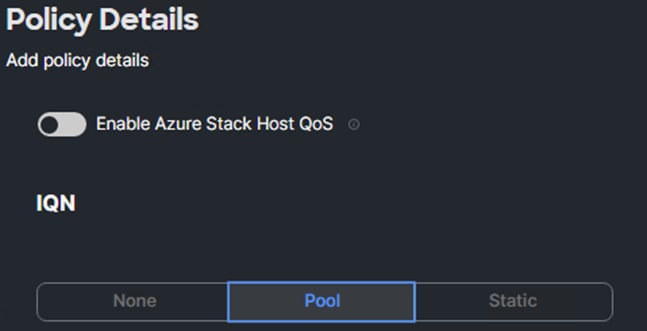
Step 5. Verify the correct organization is selected from the drop-down list (for example, AA07) and provide a name for the IQN Pool (for example, AA07-IQN Pool).
Step 6. Click Next.
Step 7. Provide the values for Prefix and IQN Block to create the IQN pool.
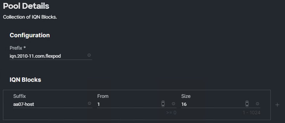
Step 8. Click Create.
Step 9. Under vNIC Configuration, select Manual vNICs Placement.
Step 10. Click Add vNIC.
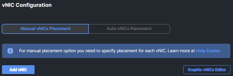
Procedure 7. Create MAC Address Pool for Fabric A and B
Note: When creating the first vNIC, the MAC address pool has not been defined yet therefore a new MAC address pool will need to be created. Two separate MAC address pools are configured for each Fabric. MAC-Pool-A will be reused for all Fabric-A vNICs, and MAC-Pool-B will be reused for all Fabric-B vNICs.
| Pool Name |
Starting MAC Address |
Size |
vNICs, if bare-metal install |
vNICs, if virtualized install |
| MAC-Pool-A |
00:25:B5:07:0A:00 |
128* |
HANA-Admin, HANA-Backup, 04-ISCSI-A |
01-vSwitch0-A, 03-VDS0-A, 05-ISCSI-A |
| MAC-Pool-B |
00:25:B5:07:0B:00 |
128* |
HANA-Replication, HANA-Shared, 05-ISCSI-B |
02-vSwitch0-B, 04-VDS0-B, 06-ISCSI-B |
Note: Each server requires 3 MAC addresses from the pool. Adjust the size of the pool according to your requirements.
Step 1. Click Select Pool under MAC Address Pool and click Create New.
Step 2. Verify the correct organization is selected from the drop-down list (for example, AA07) and provide a name for the pool from Table 14 depending on the vNIC being created (for example, MAC-Pool-A for Fabric A).
Step 3. Click Next.
Step 4. Provide the starting MAC address from Table 14 (for example, 00:25:B5:07:0A:00)
Note: For ease of troubleshooting FlexPod, some additional information is always coded into the MAC address pool. For example, in the starting address 00:25:B5:07::00, 07 is the rack number and 0A indicates Fabric A.
Step 5. Provide the size of the MAC address pool from Table 14 (for example, 128).
Step 6. Click Create to finish creating the MAC address pool.
Step 7. From the Add vNIC window, provide vNIC Name, Switch ID, and PCI Order information from Table 12 or Table 13 based on the use-case, selecting Simple placement.
Step 8. For Consistent Device Naming (CDN), from the drop-down list, select vNIC Name.
Step 9. Enable Failover if using bare-metal system vNICs. Failover will be provided by attaching multiple NICs to the VMware vSwitch and vDS, in case of virtualized scenario.
Procedure 8. Create Ethernet Network Group Policy
Ethernet Network Group policies will be created and reused on applicable vNICs as covered below. The ethernet network group policy defines the VLANs allowed for a particular vNIC, therefore multiple network group policies will be defined for this deployment as listed in Table 15 and Table 16
Table 15. Ethernet Group Policy Values for vNICs of virtualized SAP HANA Scale-up System
| Group Policy Name |
Native VLAN |
VLANs |
Apply to vNICs |
| AA07-vSwitch0-NetGrp |
Native-VLAN (2) |
IB-MGMT (1071), Infra-NFS (1075) |
01-vSwitch0-A, 02-vSwitch0-B |
| AA07-vDS0-NetGrp |
Native-VLAN (2) |
Application Traffic, vMotion (1072) HANA-Shared (1077), HANA-Data (1074), HANA-Log (1076) |
03-VDS0-A, 04-VDS0-B |
| AA07-ISCSI-A-vLAN-Policy |
iSCSI-A-VLAN (1078) |
iSCSI-A |
05-ISCSI-A |
| AA07-ISCSI-B-vLAN-Policy |
iSCSI-B-VLAN (1079) |
iSCSI-B |
06-ISCSI-B |
*Application Traffic includes HANA-Appserver, HANA Replication networks and the like that are use-case driven.
Table 16. Ethernet Group Policy Values for vNICs of bare-metal SAP HANA Scale-up System
| Group Policy Name |
Native VLAN |
VLANs |
Apply to vNICs |
| IB-MGMT (1071) |
IB-MGMT (1071) |
01-HANA-Admin |
|
| AA07-HANA-Shared-vLAN-Pol |
HANA-Shared (1077) |
HANA-Shared (1077) |
02-HANA-Shared |
| AA07-HANA-Appserver-vLAN-Pol |
HANA-Appserver (75) |
HANA-shared (75) |
03-HANA-Appserver |
| AA07-HANA-Replication-vLAN-Pol |
HANA-Replication (1073) |
HANA-Replication (1073) |
04-HANA-Replication |
| AA07-ISCSI-A-vLAN-Policy |
iSCSI-A (1078) |
iSCSI-A (1078) |
05-ISCSI-A |
| AA07-ISCSI-B-vLAN-Policy |
iSCSI-B (1079) |
iSCSI-B (1079) |
06-ISCSI-B |
| AA07-HANA-Data-vLAN-Pol |
HANA-Data (1074) |
HANA-Data (1074) |
07-HANA-Data |
| AA07-HANA-Log-vLAN-Pol |
HANA-Log (1076) |
HANA-Log (1076) |
08-HANA-log |
Step 1. Click Select Policy under Ethernet Network Group Policy and click Create New.
Step 2. Verify correct organization is selected from the drop-down list (for example, AA07) and provide a name for the policy from the Table 15 and Table 16 (for example, AA07-vSwitch0-NetGrp).
Step 3. Click Next.
Step 4. Enter the allowed VLANs (for example, 1071,1075) and the native VLAN ID from Table 16 (for example, 1071).
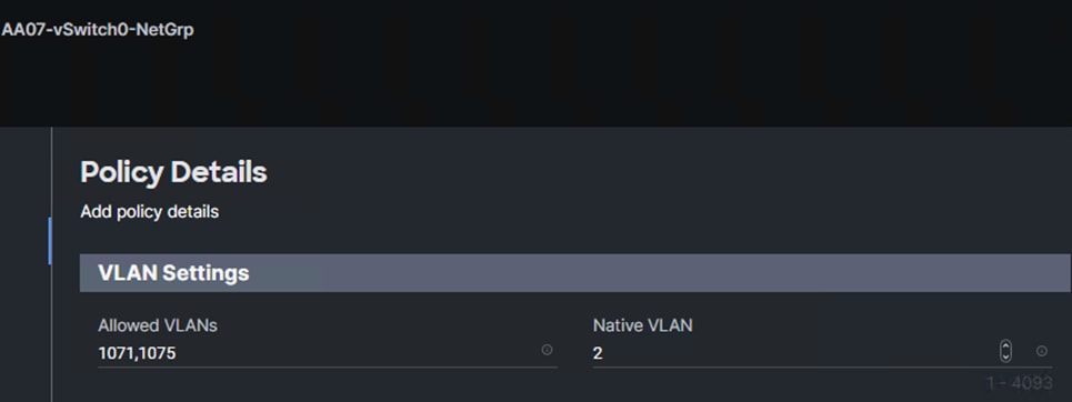
Step 5. Click Create to finish configuring the Ethernet network group policy.
Note: When ethernet group policies are shared between two vNICs, the ethernet group policy only needs to be defined for the first vNIC. For subsequent vNIC policy mapping, click Select Policy and pick the previously defined ethernet group policy from the list.
Procedure 9. Create Ethernet Network Control Policy
The Ethernet Network Control Policy is used to enable Cisco Discovery Protocol (CDP) and Link Layer Discovery Protocol (LLDP) for the vNICs. A single policy will be created here and reused for all the vNICs.
Step 1. Click Select Policy under Ethernet Network Control Policy and click Create New.
Step 2. Verify correct organization is selected from the drop-down list (for example, AA07) and provide a name for the policy (for example, AA07-Enable-CDP-LLDP).
Step 3. Click Next.
Step 4. Under LLDP, enable Cisco Discovery Protocol and Enable Transmit and Enable Receive.
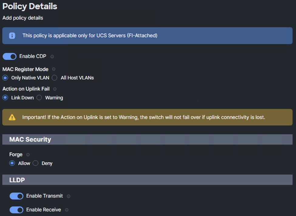
Step 5. Click Create to finish creating Ethernet network control policy.
Procedure 10. Create Ethernet QoS Policy
Note: The Ethernet QoS policy is used to enable jumbo maximum transmission units (MTUs) for all the vNICs. A single policy will be created and reused for all the vNICs.
Step 1. Click Select Policy under Ethernet QoS and click Create New.
Step 2. Verify correct organization is selected from the drop-down list (for example, AA07) and provide a name for the policy (for example, AA07-EthernetQos-Policy).
Step 3. Click Next.
Step 4. Change the MTU Bytes value to 9000.
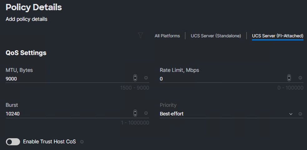
Step 5. Click Create to finish setting up the Ethernet QoS policy.
Procedure 11. Create Ethernet Adapter Policy
The ethernet adapter policy is used to set the interrupts and the send and receive queues. The values are set according to the best-practices guidance for the operating system in use. Cisco Intersight provides default VMware Ethernet Adapter policy for typical VMware deployments and Linux Ethernet Adapter policy for bare-metal deployments
Optionally, you can configure a tweaked ethernet adapter policy for additional hardware receive queues handled by multiple CPUs in scenarios where there is a lot of vMotion traffic and multiple flows. In this deployment, a modified ethernet adapter policy, AA17-VMware-High-Traffic, is created and attached to the 03-VDS0-A and 04-VDS0-B interfaces which handle vMotion.
Table 17. Ethernet Adapter Policy association to vNICs
| Policy Name |
vNICs |
Use-case |
| AA07-EthAdapter-VMware-Policy |
01-vSwitch0-A, 02-vSwitch0-B, |
Virtualized SAP HANA Scale-up system |
| AA07-EthAdapter-VMware-High-Trf |
03-VDS0-A, 04-VDS0-B |
|
| AA07-EthAdapter-Linux-Policy |
01-HANA-Admin |
Bare-metal SAP HANA Scale-up system |
| AA07-EthAdapter-Linux-High-Trf |
03-HANA-Appserver, 04-HANA-Replication, 02-HANA-Shared, 07-HANA-Data, 08-HANA-Log |
Step 1. Click Select Policy under Ethernet Adapter and click Create New.
Step 2. Verify correct organization is selected from the drop-down list (for example, AA07) and provide a name for the policy (for example, AA07-EthAdapter-VMware-Policy).
Step 3. Click Select Default Configuration under Ethernet Adapter Default Configuration.
Step 4. From the list, select VMware.
Step 5. Click Next.
Step 6. For the AA07-EthAdapter-VMware-Policy, click Create and skip the rest of the steps in this “Create Ethernet Adapter Policy” procedure.
Step 7. For the AA07-EthAdapter-VMware-High-Trf policy (for vDS0 interfaces), make the following modifications to the policy:
● Increase Interrupts to 11
● Increase Receive Queue Count to 8
● Increase Receive Ring Size to 4096
● Increase Transmit Ring Size to 4096
● Increase Completion Queue Count to 9
● Enable Receive Side Scaling
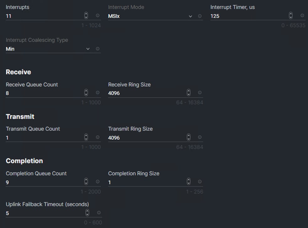

Step 8. Click Select Policy under Ethernet Adapter and click Create New.
Step 9. Verify correct organization is selected from the drop-down list (for example, AA07) and provide a name for the policy (for example, AA07-EthAdapter-Linux-Policy).
Step 10. Click Select Default Configuration under Ethernet Adapter Default Configuration.
Step 11. From the list, select Linux.
Step 12. Click Next.
Step 13. For the AA07-EthAdapter-Linux-Policy, click Create and skip the rest of the steps in this “Create Ethernet Adapter Policy” procedure.
Step 14. For the AA07-EthAdapter-Linux-High-Trf policy, make the following modifications to the policy:
● Increase Interrupts to 11
● Increase Receive Queue Count to 8
● Increase Receive Ring Size to 4096
● Increase Transmit Ring Size to 4096
● Increase Completion Queue Count to 9
● Enable Receive Side Scaling
Note: For all the non-ISCSI vNIC, skip the iSCSI-A and iSCSI-B policy creation sections.
Procedure 12. Create iSCSI-A Policy
Note: The iSCSI-A policy is only applied to vNICs 05-ISCSI-A and should not be created for data vNICs (vSwitch0 and VDS). The iSCSI-B policy creation is explained next.
To create this policy, the following information will be gathered from NetApp:
iSCSI Target:
AA07-A400::> iscsi show -vserver -AA07-Infra-SVM
Vserver: AA07-Infra-SVM
Target Name: iqn.1992-08.com.netapp:sn.2e1dbb145eec11edaf02d039ea29d44a:vs.14
Target Alias: AA07-Infra-SVM
Administrative Status: up
iSCSI LIFs:
AA07-A400::> network interface show -vserver AA07-Infra-SVM -data-protocol iscsi
Logical Status Network Current Current Is
Vserver Interface Admin/Oper Address/Mask Node Port Home
----------- ---------- ---------- ------------------ ------------- ------- ----
AA07-Infra-SVM
iscsi-lif-01a
up/up 10.107.8.1/24 AA07-A400-01 a0a-1078
true
iscsi-lif-01b
up/up 10.107.9.1/24 AA07-A400-01 a0a-1079
true
iscsi-lif-02a
up/up 10.107.8.2/24 AA07-A400-02 a0a-1078
true
iscsi-lif-02b
up/up 10.107.9.2/24 AA07-A400-02 a0a-1079
true
4 entries were displayed.
Step 1. Click Select Policy under iSCSI Boot and click Create New.
Step 2. Verify correct organization is selected from the drop-down list (for example, AA07) and provide a name for the policy (for example, AA07-ISCSI-A-Boot-Policy).
Step 3. Click Next.
Step 4. Select Static under Configuration.
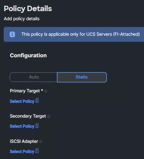
Step 5. Click Select Policy under Primary Target and click Create New.
Step 6. Verify correct organization is selected from the drop-down list (for example, AA07) and provide a name for the policy (for example, AA07-ISCSI-A-Primary-Target).
Step 7. Click Next.
Step 8. Provide the Target Name captured from NetApp, IP Address of iscsi-lif-01a, Port 3260 and Lun ID of 0.
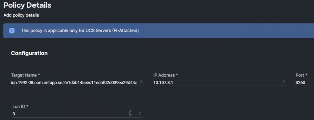
Step 9. Click Create.
Step 10. Click Select Policy under Secondary Target and click Create New.
Step 11. Verify correct organization is selected from the drop-down list (for example, AA07) and provide a name for the policy (for example, AA07-ISCSI-A-Secondary-Target).
Step 12. Click Next.
Step 13. Provide the Target Name captured from NetApp, IP Address of iscsi-lif-02a, Port 3260 and Lun ID of 0.
Step 14. Click Create.
Step 15. Click Select Policy under iSCSI Adapter and click Create New.
Step 16. Verify correct organization is selected from the drop-down list (for example, AA07) and provide a name for the policy (for example, AA07-ISCSI-Adapter-Policy).
Step 17. Click Next.
Step 18. Accept the default policies. You can adjust the timers if necessary.
Step 19. Click Create.
Step 20. Scroll down to Initiator IP Source and make sure Pool is selected.
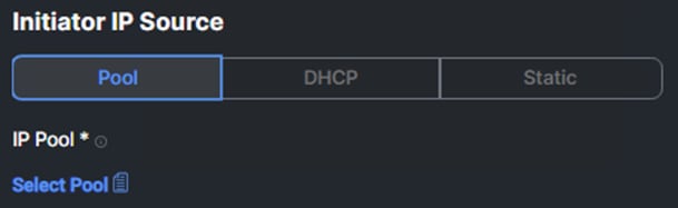
Step 21. Click Select Pool under IP Pool and click Create New.
Step 22. Verify correct organization is selected from the drop-down list (for example, AA07) and provide a name for the pool (for example, AA07-ISCSI-A-IP-Pool).
Step 23. Click Next.
Step 24. Make sure Configure IPv4 Pool is selected. Enter the IP pool information for iSCSI-A subnet.
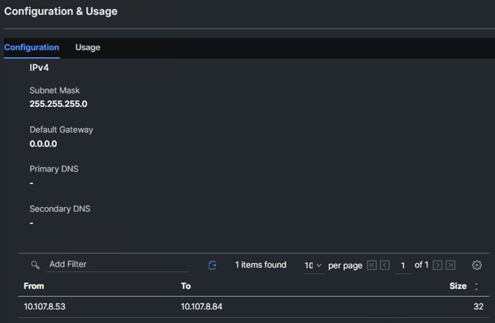
Note: Since the iSCSI network is not routable but the Gateway parameter is required, enter 0.0.0.0 for the Gateway. This will result in a gateway not being set for the interface.
Step 25. Click Next.
Step 26. Disable Configure IPv6 Pool.
Step 27. Click Create.
Step 28. Verify all the policies and pools are correctly mapped for the iSCSI-A policy.
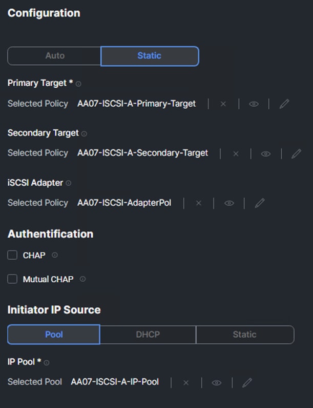
Step 29. Click Create.
Procedure 13. Create iSCSI-B Policy
Note: The iSCSI-B policy is only applied to vNIC 06-ISCSI-B and should not be created for data vNICs (vSwitch0 and vDS0).
Note: To create this policy, the following information will be gathered from NetApp:
iSCSI Target:
AA07-A400::> iscsi show -vserver AA07-Infra-SVM
Vserver: AA07-Infra-SVM
Target Name: iqn.1992-08.com.netapp:sn.2e1dbb145eec11edaf02d039ea29d44a:vs.14
Target Alias: AA07-Infra-SVM
Administrative Status: up
iSCSI LIFs:
AA07-A400::> network interface show -vserver AA07-Infra-SVM -data-protocol iscsi
Logical Status Network Current Current Is
Vserver Interface Admin/Oper Address/Mask Node Port Home
----------- ---------- ---------- ------------------ ------------- ------- ----
AA07-Infra-SVM
iscsi-lif-01a
up/up 10.107.8.1/24 AA07-A400-01 a0a-1078
true
iscsi-lif-01b
up/up 10.107.9.1/24 AA07-A400-01 a0a-1079
true
iscsi-lif-02a
up/up 10.107.8.2/24 AA07-A400-02 a0a-1078
true
iscsi-lif-02b
up/up 10.107.9.2/24 AA07-A400-02 a0a-1079
true
4 entries were displayed.
Step 1. Click Select Policy under iSCSI Boot and click Create New.
Step 2. Verify correct organization is selected from the drop-down list (for example, AA07) and provide a name for the policy (for example, AA07-iSCSI-Boot-B).
Step 3. Click Next.
Step 4. Select Static under Configuration.
Step 5. Click Select Policy under Primary Target and click Create New.
Step 6. Verify correct organization is selected from the drop-down list (for example, AA07) and provide a name for the policy (for example, AA07-ISCSI-B-Primary-Target).
Step 7. Click Next.
Step 8. Provide the Target Name captured from NetApp, IP Address of iscsi-lif-01b, Port 3260 and LUN ID of 0.
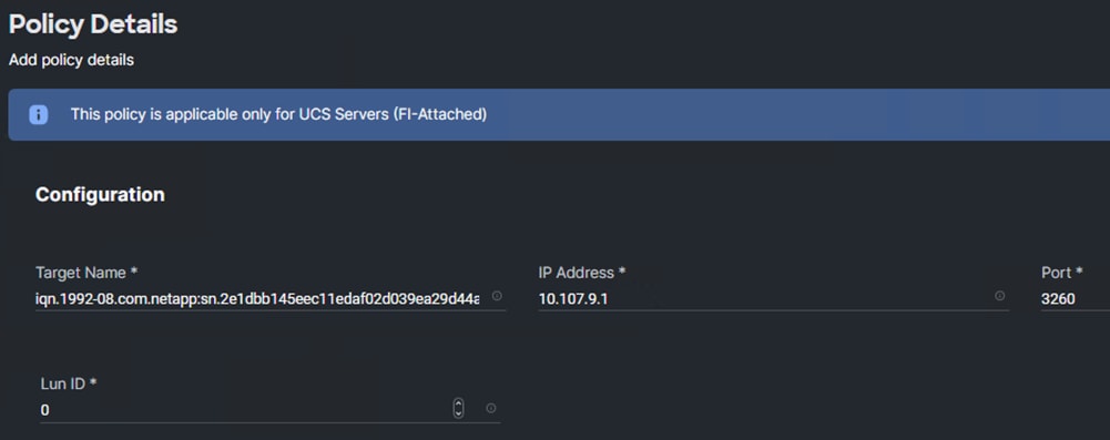
Step 9. Click Create.
Step 10. Click Select Policy under Secondary Target and click Create New.
Step 11. Verify correct organization is selected from the drop-down list (for example, AA07) and provide a name for the policy (for example, AA07-ISCSI-B-Secondary-Target).
Step 12. Click Next.
Step 13. Provide the Target Name captured from NetApp, IP Address of iscsi-lif02b, Port 3260 and Lun ID of 0.
Step 14. Click Create.
Step 15. Click Select Policy under iSCSI Adapter and select the previously configured adapter policy AA07-ISCSI-Adapter-Policy.
Step 16. Scroll down to Initiator IP Source and make sure Pool is selected.
Step 17. Click Select Pool under IP Pool and click Create New.
Step 18. Verify correct organization is selected from the drop-down list (for example, AA07) and provide a name for the pool (for example, AA07-ISCSI-B-IP-Pool).
Step 19. Click Next.
Step 20. Make sure Configure IPv4 Pool is selected. Enter the IP pool information for iSCSI-B subnet.
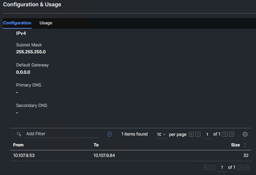
Note: Since the iSCSI network is not routable but the Gateway parameter is required, enter 0.0.0.0 for the Gateway. This will result in a gateway not being set for the interface.
Step 21. Click Next.
Step 22. Disable Configure IPv6 Pool.
Step 23. Click Create.
Step 24. Verify all the policies and pools are correctly mapped for the iSCSI-B policy.
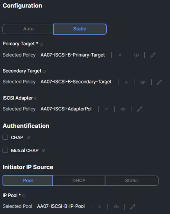
Step 25. Click Create.
Step 26. Click Create to finish creating the vNIC.
Step 27. Go back to Step 10 of Procedure 6 Add vNIC and repeat the vNIC creation for rest of all required vNICs reusing the created pools and policies wherever possible.
Step 28. Verify all required vNICs were successfully created.
Figure 4. vNIC configuration snapshot From the bare-metal SAP HANA Scale-up system configuration
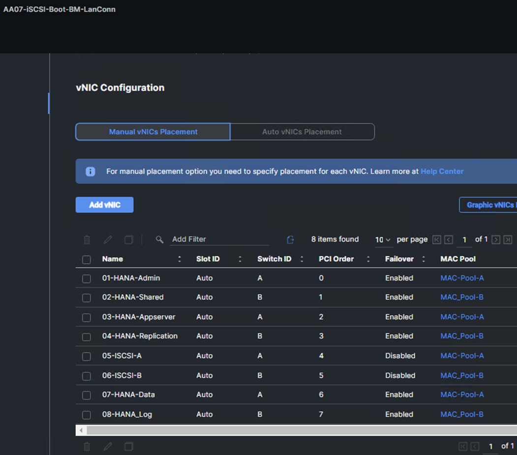
Figure 5. vNIC configuration snapshot from the virtualized SAP HANA system configuration
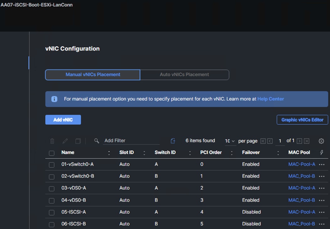
Step 29. Click Create to finish creating the LAN Connectivity policy for iSCSI hosts.
Procedure 14. Create LAN Connectivity Policy for FC Hosts
The FC boot from SAN hosts use four vNICs configured as listed in Table 18 and Table 19
Table 18. vNICs for LAN Connectivity policy for FC San booting ESXi host part of virtualized SAP HANA setup
| vNIC Name |
Switch ID |
PCI Order |
VLANs |
| 01-vSwitch0-A |
A |
2 |
IB-MGMT, Infra-NFS |
| 02-vSwitch0-B |
B |
3 |
IB-MGMT, Infra-NFS |
| 03-vDS0-A |
A |
4 |
Application Traffic, vMotion, HANA-Shared, HANA-Data, HANA-Log |
| 04-vDS0-B |
B |
5 |
Application Traffic, vMotion, HANA-Shared, HANA-Data, HANA-Log |
Note: *Application Traffic includes HANA-Appserver, HANA Replication networks and the like that are use-case driven.
Table 19. vNICs for LAN Connectivity policy for FC SAN booting bare-metal SAP HANA node
| vNIC Name |
Switch ID |
PCI Order |
VLANs |
| 01-HANA-Admin |
A |
2 |
IB-MGMT (1071) |
| 02-HANA-Shared |
B |
3 |
HANA-Shared (1077) |
| 03-HANA-Appserver |
A |
4 |
HANA-Appserver (76) |
| 04-HANA-Replication |
B |
5 |
HANA-Replication (1073) |
Step 1. Click Select Policy next to LAN Connectivity and click Create New.
Step 2. Verify correct organization is selected from the drop-down list (for example, AA07) and provide a name for the policy (for example, AA07-FC-ESXi-LanCon in case of virtualized node or AA07-FC-BM-LanConn in case of bare-metal SAP HANA node). Select UCS Server (FI-Attached). Click Next.
Step 3. The four vNICs created in the LAN Connectivity Policy for FC Hosts are identical to the first four vNICs in the LAN Connectivity Policy for iSCSI Hosts. Follow Procedure 6, starting at Step 9, only creating the first four vNICs (excluding the iSCSI vNICs).
Step 4. Verify all four vNICs were successfully created.
Figure 6. vNIC configuration for ESXi host part of virtualized SAP HANA setup
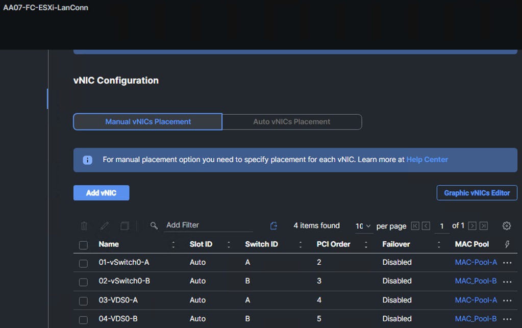
Figure 7. vNIC config from FC SAN booting bare-metal SAP HANA node
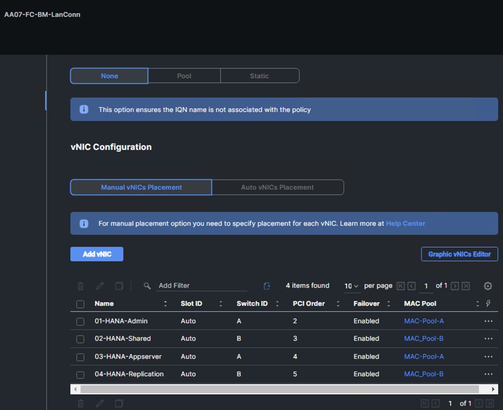
Step 5. Click Create to finish creating the LAN Connectivity policy for FC hosts.
Note: With FC connectivity observe that the vNICs are placed starting with order no.2 as the first two is slots 0 and 1 will be taken by the vHBAs that would be configured in the next step for SAN connectivity.
Procedure 15. Create Network Connectivity - SAN Connectivity
A SAN connectivity policy determines the network storage resources and the connections between the server and the storage device on the network. This policy enables customers to configure the vHBAs that the servers use to communicate with the SAN.
Note: A SAN Connectivity policy is not needed for iSCSI boot from SAN hosts and can be skipped.
Table 20 lists the details of two vHBAs that are used to provide FC connectivity and boot from SAN functionality.
Table 20. vHBA for boot from FC SAN
| vNIC/vHBA Name |
Switch ID |
PCI Order |
| vHBA-A |
A |
0 |
| vHBA-B |
B |
1 |
Step 1. Click Select Policy next to SAN Connectivity and click Create New.
Step 2. Verify correct organization is selected from the drop-down list (for example, AA07) and provide a name for the policy (for example, AA07-SanCon-Pol). Select UCS Server (FI-Attached). Click Next.
Step 3. Select Manual vHBAs Placement.
Step 4. Select Pool under WWNN Address.
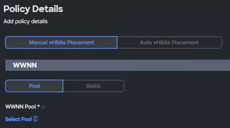
Procedure 16. Create the WWNN Address Pool
The WWNN address pools have not been defined yet therefore a new WWNN address pool has to be defined.
Step 1. Click Select Pool under WWNN Address Pool and click Create New.
Step 2. Verify correct organization is selected from the drop-down list (for example, AA07) and provide a name for the policy (for example, AA07-WWNN-Pool).
Step 3. Click Next.
Step 4. Provide the starting WWNN block address and the size of the pool.
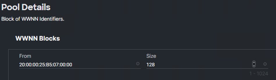
Note: As a best practice, in FlexPod some additional information is always coded into the WWNN address pool for ease of troubleshooting. For example, in the address 20:00:00:25:B5:07:00:00, 07 is the rack number.
Step 5. Click Create to finish creating the WWNN address pool.
Procedure 17. Create the vHBA-A for SAN A
Step 1. Click Add vHBA.
Step 2. For vHBA Type, select fc-initiator from the drop-down list.
Procedure 18. Create the WWPN Pool for SAN A
The WWPN address pool has not been defined yet therefore a WWPN address pool for Fabric A will be defined.
Step 1. Click Select Pool under WWPN Address Pool and click Create New.
Step 2. Verify correct organization is selected from the drop-down list (for example, AA07) and provide a name for the policy (for example, AA07-WWPN-Pool-A).
Step 3. Provide the starting WWPN block address for SAN A and the size.
Note: As a best practice, in FlexPod some additional information is always coded into the WWPN address pool for ease of troubleshooting. For example, in the address 20:00:00:25:B5:A7:0A:00, 07 is the rack number and 0A signifies SAN A.
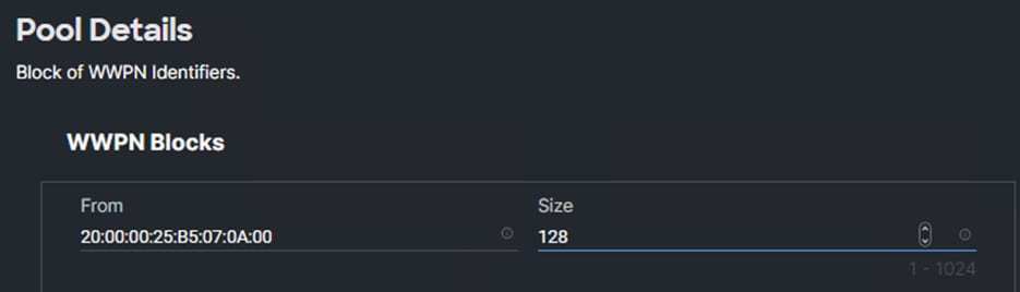
Step 4. Click Create to finish creating the WWPN pool.
Step 5. In the Create vHBA window, using Simple Placement, provide the Name (for example, FCP-Fabric-A), vHBA Type, Switch ID (for example, A) and PCI Order from Table 20.
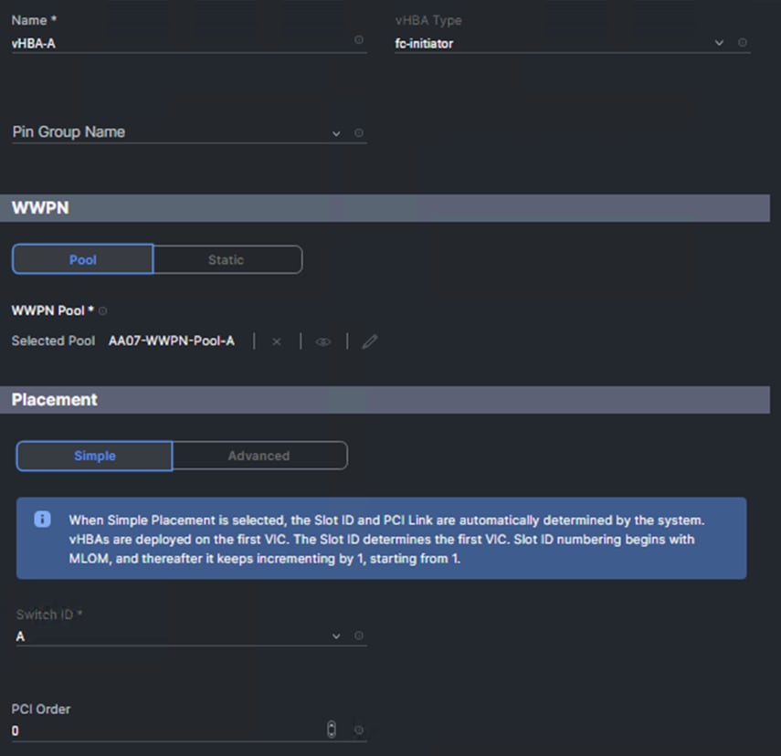
Procedure 19. Create Fibre Channel Network Policy for SAN A
A Fibre Channel network policy governs the VSAN configuration for the virtual interfaces. In this deployment, VSAN 101 will be used for vHBA-A.
Step 1. Click Select Policy under Fibre Channel Network and click Create New.
Step 2. Verify correct organization is selected from the drop-down list (for example, AA07) and provide a name for the policy (for example, AA07-SAN-A-Network).
Step 3. Under VSAN ID, provide the VSAN information (for example, 101).
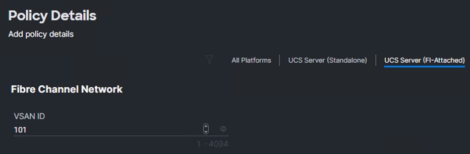
Step 4. Click Create to finish creating the Fibre Channel network policy.
Procedure 20. Create Fibre Channel QoS Policy
The Fibre Channel QoS policy assigns a system class to the outgoing traffic for a vHBA. This system class determines the quality of service for the outgoing traffic. The Fibre Channel QoS policy used in this deployment uses default values and will be shared by all vHBAs.
Step 1. Click Select Policy under Fibre Channel QoS and click Create New.
Step 2. Verify correct organization is selected from the drop-down list (for example, AA07) and provide a name for the policy (for example, AA07-FC-QoS).
Step 3. For the scope, select UCS Server (FI-Attached).
Step 4. Do not change the default values on the Policy Details screen.
Step 5. Click Create to finish creating the Fibre Channel QoS policy.
Procedure 21. Create Fibre Channel Adapter Policy
A Fibre Channel adapter policy governs the host-side behavior of the adapter, including the way that the adapter handles traffic. This validation uses the default values for the adapter policy, and the policy will be shared by all the vHBAs.
Step 1. Click Select Policy under Fibre Channel Adapter and click Create New.
Step 2. Verify correct organization is selected from the drop-down list (for example, AA07) and provide a name for the policy (for example, AA07-FC-Adapter).
Step 3. Under Fibre Channel Adapter Default Configuration, click Select Default Configuration.
Step 4. Select VMware and click Next.
Step 5. For the scope, select UCS Server (FI-Attached).
Step 6. Do not change the default values on the Policy Details screen.
Step 7. Click Create to finish creating the Fibre Channel adapter policy.
Step 8. Click Add to create vHBA vHBA-A.
Procedure 22. Create the vHBA for SAN B
Step 1. Click Add vHBA.
Step 2. For vHBA Type, select fc-initiator from the drop-down list.
Procedure 23. Create the WWPN Pool for SAN B
The WWPN address pool has not been defined yet therefore a WWPN address pool for Fabric B will be defined.
Step 1. Click Select Pool under WWPN Address Pool and click Create New.
Step 2. Verify correct organization is selected from the drop-down list (for example, AA07) and provide a name for the policy (for example, AA07-WWPN-Pool-B).
Step 3. Provide the starting WWPN block address for SAN B and the size.
Note: As a best practice, in FlexPod some additional information is always coded into the WWPN address pool for ease of troubleshooting. For example, in the address 20:00:00:25:B5:07:0B:00, 07 is the rack number and 0B signifies SAN B.
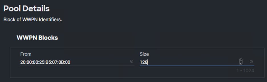
Step 4. Click Create to finish creating the WWPN pool.
Step 5. In the Create vHBA window, under Simple Placement, provide the Name (for example, FCP-Fabric-B), Switch ID (for example, B) and PCI Order from Table 20.
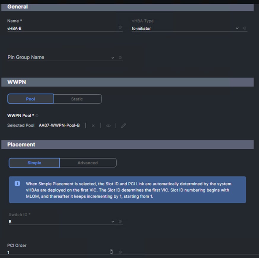
Procedure 24. Create Fibre Channel Network Policy for SAN B
Note: In this deployment, VSAN 102 is used for vHBA FCP-Fabric-B.
Step 1. Click Select Policy under Fibre Channel Network and click Create New.
Step 2. Verify correct organization is selected from the drop-down list (for example, AA07) and provide a name for the policy (for example, AA07-SAN-B-Network).
Step 3. Under VSAN ID, provide the VSAN information (for example, 102).
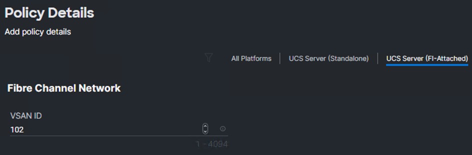
Step 4. Click Create.
Step 5. Select the Fibre Channel QoS Policy for SAN B; click Select Policy under Fibre Channel QoS and select the previously created QoS policy AA07-FC-QoS.
Step 6. Select the Fibre Channel Adapter Policy for SAN B; click Select Policy under Fibre Channel Adapter and select the previously created Adapter policy AA07-FC-Adapter.
Step 7. Verify all the vHBA policies are mapped.
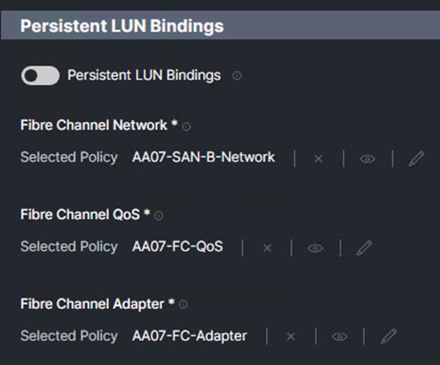
Step 8. Click Add to add the vHBA FCP-Fabric-B.
Step 9. Verify both the vHBAs are added to the SAN connectivity policy.
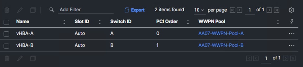
Step 1. When the LAN connectivity policy and SAN connectivity policy (for FC) is created, click Next to move to the Summary screen.
Step 2. On the summary screen, verify the policies are mapped to various settings. The screenshot below shows the summary view for an iSCSI boot from SAN server profile template for bare-metal use case.
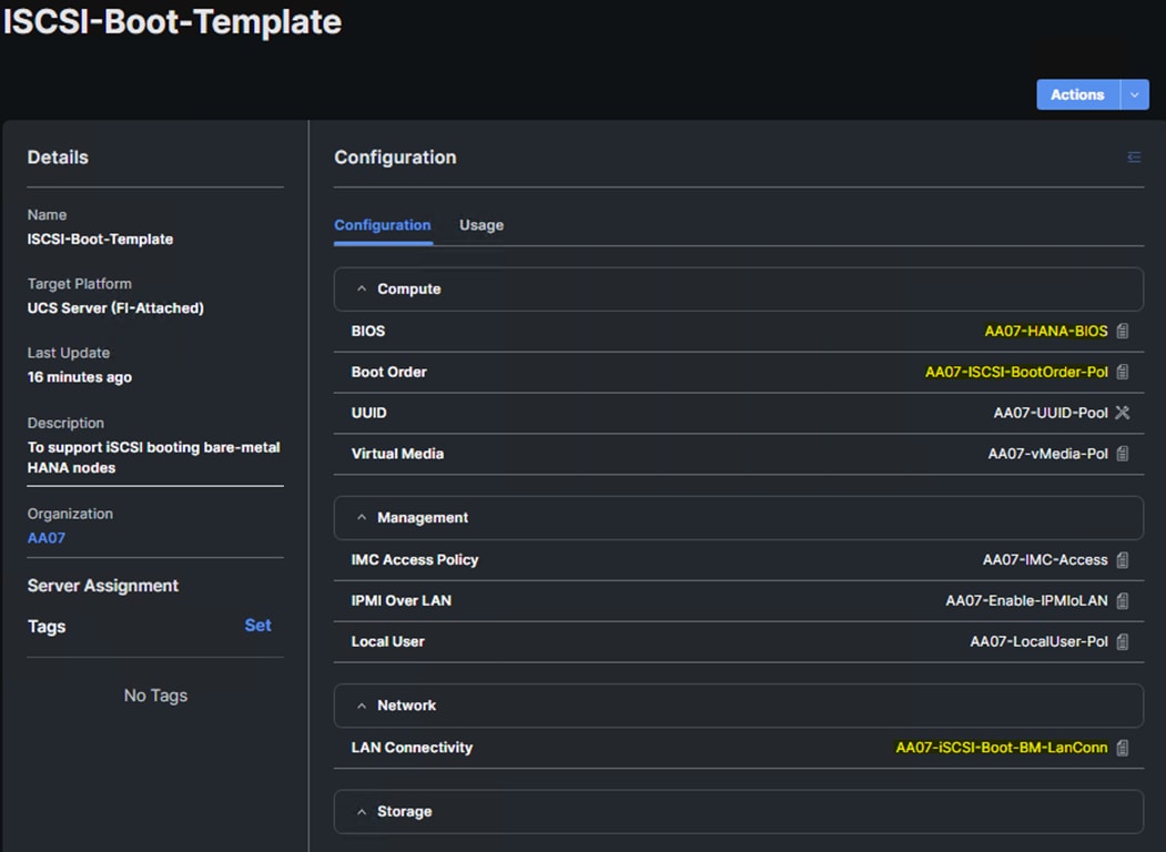
Note: A FC boot from SAN server profile template for virtualized SAP HANA setup will have a different Boot Order Policy, LAN Connectivity Policy, SAN Connectivity Policy, and BIOS Policy.
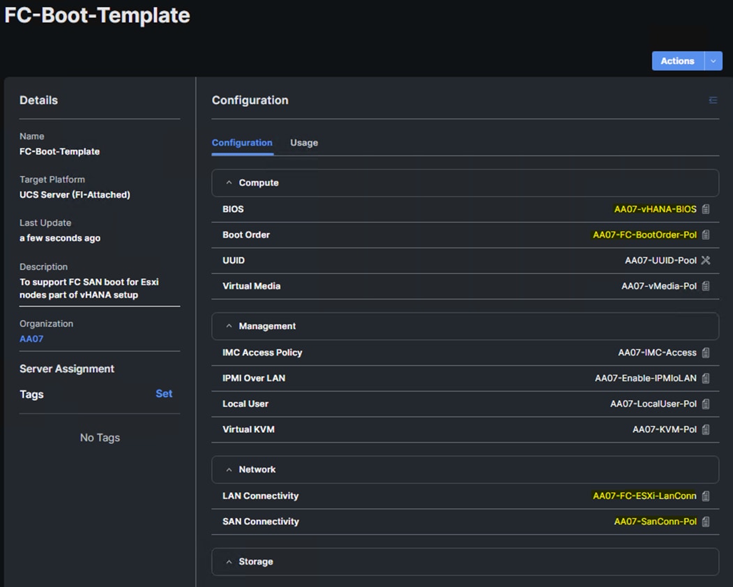
Note: A FC boot form SAN server profile template will have a different LAN connectivity Policy and BIOS policy for a bare-metal SAP HANA nodes scenario.
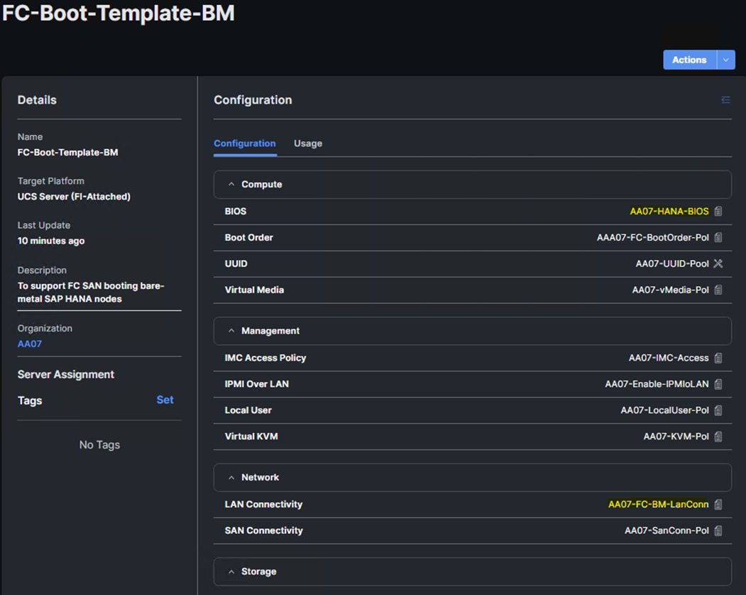
Step 3. Build additional Server Profile Templates for different boot options, CPU types, and VIC types.
Cisco UCS IMM Setup Completion
Procedure 1. Derive Server Profiles
Step 1. From the Server profile template Summary screen, click Derive Profiles.
Note: This action can also be performed later by navigating to Templates, clicking “…” next to the template name and selecting Derive Profiles.
Step 2. Under the Server Assignment, select Assign Now and select Cisco UCS X210c M6 server(s). You can select one or more servers depending on the number of profiles to be deployed.
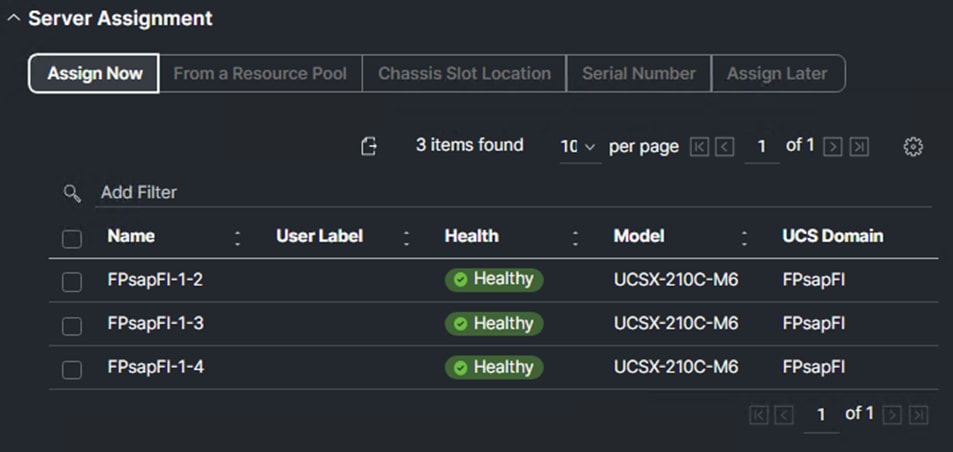
Step 3. Click Next.
Note: Cisco Intersight will fill in the default information for the number of servers selected (1 in this case).
Step 4. Adjust the fields as needed. It is recommended to use the server hostname for the Server Profile name.
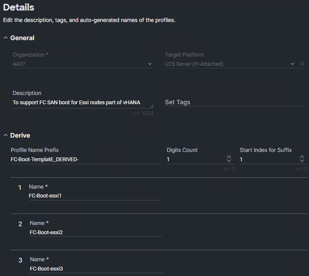
Step 5. Click Next.
Step 6. Verify the information and click Derive to create the Server Profile(s).
Step 7. In the Infrastructure Service > Configure > Profiles > UCS Server Profiles list, select the profile(s) just created and click the … and select Deploy. Click Deploy to confirm.
Note: Cisco Intersight will start deploying the server profile(s) and will take some time to apply all the policies. Use the Requests tab at the top right-hand corner of the window to see the progress.
When the Server Profile(s) are deployed successfully, they will appear under the Server Profiles with the status of OK.
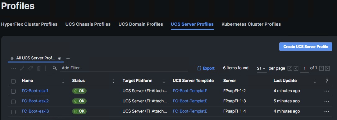
Procedure 2. Derive Service profile from FC-Boot-Template-BM
Step 1. Navigate to Templates, click “…”and select Derive Profiles.
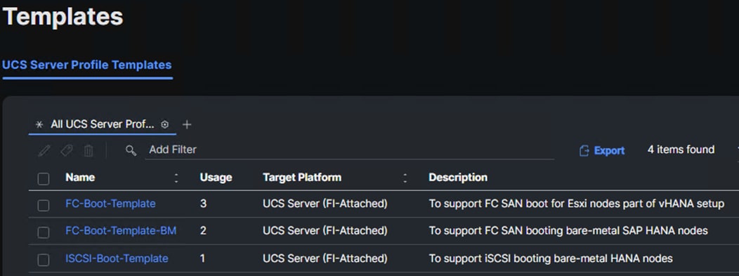
Step 2. Click Next to generate profile for FC boot from SAN bare-metal SAP HANA node preparation.
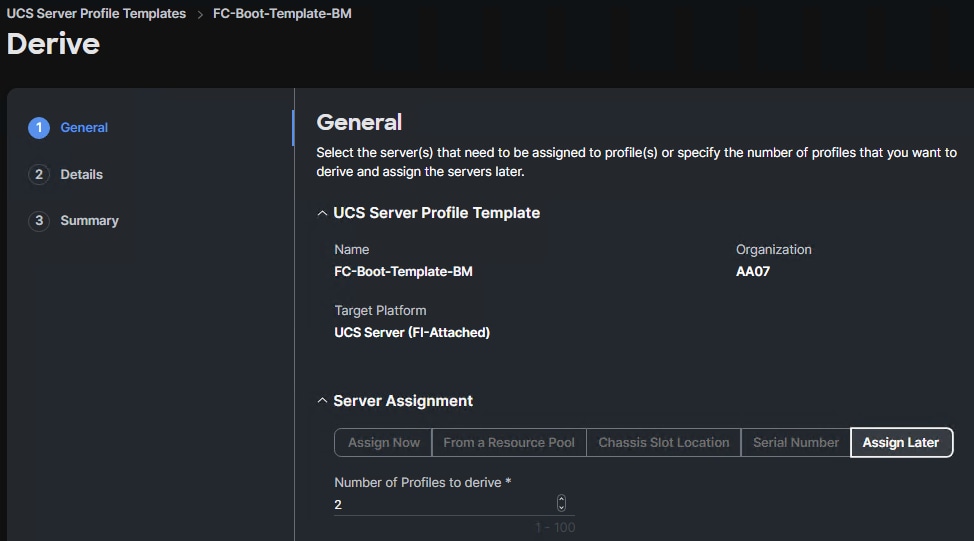
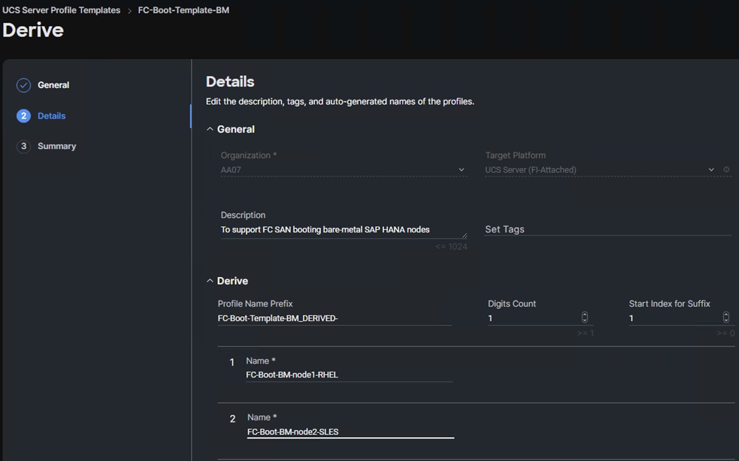
Step 3. Click Next to generate profiles.
Procedure 3. Derive Service profile from the ISCSI Boot template
Step 1. Navigate to Templates, click “…” next to the ISCI-Boot-Template name and select Derive Profiles.
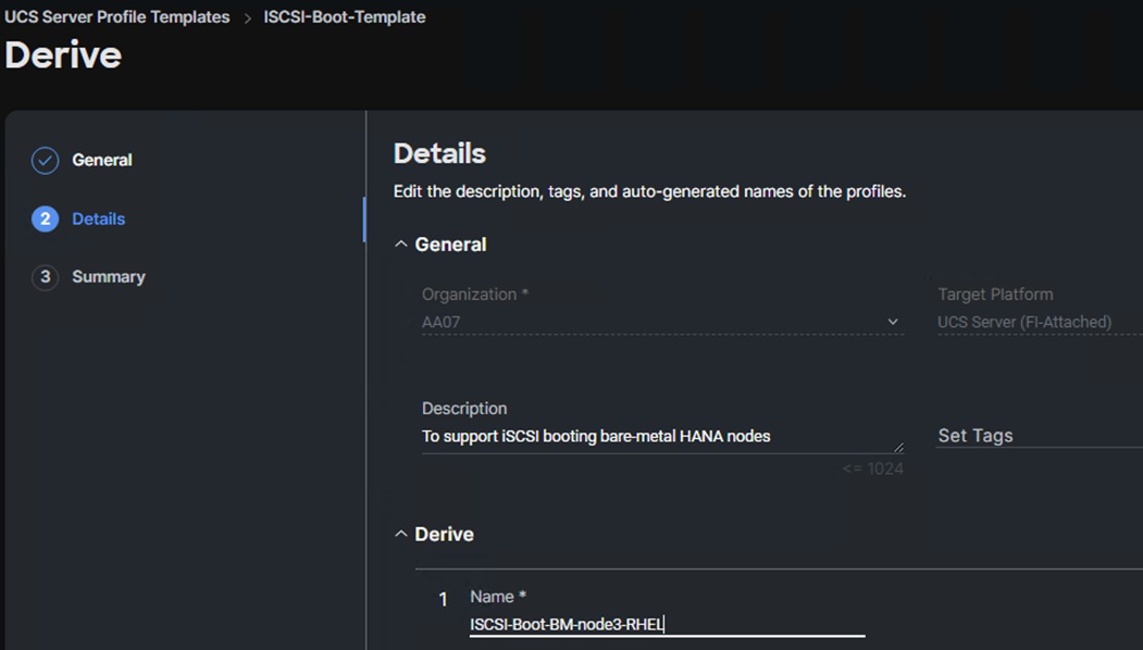
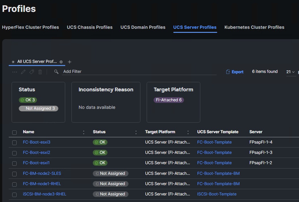
Step 2. Derive and Deploy all needed servers for your FlexPod environment.
SAN Switch Configuration – Part 1
This chapter contains the following:
● FlexPod Cisco MDS Switch Manual Configuration
This section explains how to configure the Cisco MDS 9000s for use in a FlexPod environment. The configuration detailed in this section is only needed when configuring Fibre Channel storage access.
Note: If FC connectivity is not required in the FlexPod deployment, this section can be skipped.
Follow the physical connectivity guidelines for FlexPod as explained in Physical Topology section.
The following procedures describe how to configure the Cisco MDS switches for use in a base FlexPod environment. This procedure assumes you are using the Cisco MDS 9132T with NX-OS 8.4(2c).
Procedure 1. Set up Cisco MDS 9132T A and 9132T B
Note: On initial boot and connection to the serial or console port of the switch, the NX-OS setup should automatically start and attempt to enter Power on Auto Provisioning. Enter y to get to the System Admin Account Setup.
Step 1. Configure the switch using the command line:
---- System Admin Account Setup ----
Do you want to enforce secure password standard (yes/no) [y]: Enter
Enter the password for "admin": <password>
Confirm the password for "admin": <password>
Would you like to enter the basic configuration dialog (yes/no): yes
Create another login account (yes/no) [n]: Enter
Configure read-only SNMP community string (yes/no) [n]: Enter
Configure read-write SNMP community string (yes/no) [n]: Enter
Enter the switch name : <mds-A-hostname>
Continue with Out-of-band (mgmt0) management configuration? (yes/no) [y]: Enter
Mgmt0 IPv4 address : <mds-A-mgmt0-ip>
Mgmt0 IPv4 netmask : <mds-A-mgmt0-netmask>
Configure the default gateway? (yes/no) [y]: Enter
IPv4 address of the default gateway : <mds-A-mgmt0-gw>
Configure advanced IP options? (yes/no) [n]: Enter
Enable the ssh service? (yes/no) [y]: Enter
Type of ssh key you would like to generate (dsa/rsa) [rsa]: Enter
Number of rsa key bits <1024-2048> [1024]: Enter
Enable the telnet service? (yes/no) [n]: Enter
Configure congestion/no_credit drop for fc interfaces? (yes/no) [y]: Enter
Enter the type of drop to configure congestion/no_credit drop? (con/no) [c]: Enter
Enter milliseconds in multiples of 10 for congestion-drop for logical-type edge
in range (<200-500>/default), where default is 500. [d]: Enter
Enable the http-server? (yes/no) [y]: Enter
Configure clock? (yes/no) [n]: Enter
Configure timezone? (yes/no) [n]: Enter
Configure summertime? (yes/no) [n]: Enter
Configure the ntp server? (yes/no) [n]: Enter
Configure default switchport interface state (shut/noshut) [shut]: Enter
Configure default switchport trunk mode (on/off/auto) [on]: auto
Configure default switchport port mode F (yes/no) [n]: yes
Configure default zone policy (permit/deny) [deny]: Enter
Enable full zoneset distribution? (yes/no) [n]: y
Configure default zone mode (basic/enhanced) [basic]: Enter
Step 2. Review the configuration.
Would you like to edit the configuration? (yes/no) [n]: Enter
Use this configuration and save it? (yes/no) [y]: Enter
Step 3. To set up the initial configuration of the Cisco MDS B switch, repeat steps 1 and 2 with appropriate host and IP address information.
FlexPod Cisco MDS Switch Manual Configuration
Procedure 1. Enable Features on Cisco MDS 9132T A and Cisco MDS 9132T B Switches
Step 1. Log in as admin.
Step 2. Run the following commands:
configure terminal
feature npiv
feature fport-channel-trunk
Procedure 2. Add NTP Servers and Local Time Configuration on Cisco MDS 9132T A and Cisco MDS 9132T B
Step 1. From the global configuration mode, run the following command:
ntp server <nexus-A-mgmt0-ip>
ntp server <nexus-B-mgmt0-ip>
clock timezone <timezone> <hour-offset> <minute-offset>
clock summer-time <timezone> <start-week> <start-day> <start-month> <start-time> <end-week> <end-day> <end-month> <end-time> <offset-minutes>
Note: It is important to configure the network time so that logging time alignment, any backup schedules, and SAN Analytics forwarding are correct. For more information on configuring the timezone and daylight savings time or summer time, please see Cisco MDS 9000 Series Fundamentals Configuration Guide, Release 9.x. Sample clock commands for the United States Eastern timezone are:
clock timezone EST -5 0
clock summer-time EDT 2 Sunday March 02:00 1 Sunday November 02:00 60
Procedure 1. Cisco MDS 9132T A
Step 1. From the global configuration mode, run the following commands:
channel mode active
switchport trunk allowed vsan <vsan-a-id for example, 101>
switchport description <ucs-domainname>-a
switchport speed 32000
switchport rate-mode dedicated
no shutdown
!
interface fc1/1
switchport description <st-clustername>-01:5a
switchport trunk mode off
port-license acquire
no shutdown
!
interface fc1/2
switchport description <st-clustername>-02:5a
switchport trunk mode off
port-license acquire
no shutdown
!
interface fc1/5
switchport description <ucs-domainname>-a:fc1/1
channel-group 15 force
port-license acquire
no shutdown
!
interface fc1/6
switchport description <ucs-clustername>-a:fc1/2
channel-group 15 force
port-license acquire
no shutdown
!
Procedure 2. Cisco MDS 9132T B
Step 1. From the global configuration mode, run the following commands:
interface port-channel15
channel mode active
switchport trunk allowed vsan <vsan-b-id for example, 102>
switchport description <ucs-domainname>-b
switchport speed 32000
switchport rate-mode dedicated
no shutdown
!
interface fc1/1
switchport description <st-clustername>-01:5b
switchport trunk mode off
port-license acquire
no shutdown
!
interface fc1/2
switchport description <st-clustername>-02:5b
switchport trunk mode off
port-license acquire
no shutdown
!
interface fc1/5
switchport description <ucs-domainname>-b:fc1/1
channel-group 15 force
port-license acquire
no shutdown
!
interface fc1/6
switchport description <ucs-clustername>-b:fc1/2
channel-group 15 force
port-license acquire
no shutdown
!
Note: If VSAN trunk is not configured between the Cisco UCS Fabric Interconnects and the Cisco MDS switches, do not enter “switchport trunk allowed vsan <vsan-b-id>” for interface port-channel15.
Procedure 1. Cisco MDS 9132T A
Step 1. From the global configuration mode, run the following commands:
vsan database
vsan <vsan-a-id>
vsan <vsan-a-id> name Fabric-A
exit
zone smart-zoning enable vsan <vsan-a-id>
vsan database
vsan <vsan-a-id> interface fc1/1
Traffic on fc1/1 may be impacted. Do you want to continue? (y/n) [n] y
vsan <vsan-a-id> interface fc1/2
Traffic on fc1/2 may be impacted. Do you want to continue? (y/n) [n] y
vsan <vsan-a-id> interface port-channel15
exit
Procedure 2. Cisco MDS 9132T B
Step 1. From the global configuration mode, run the following commands:
vsan database
vsan <vsan-b-id>
vsan <vsan-b-id> name Fabric-B
exit
zone smart-zoning enable vsan <vsan-b-id>
vsan database
vsan <vsan-b-id> interface fc1/1
Traffic on fc1/1 may be impacted. Do you want to continue? (y/n) [n] y
vsan <vsan-b-id> interface fc1/2
Traffic on fc1/2 may be impacted. Do you want to continue? (y/n) [n] y
vsan <vsan-b-id> interface port-channel15
exit
Procedure 1. Cisco MDS 9132T A
Step 1. The WWPN information required to create device-alias and zones can be gathered from NetApp using the following command:
network interface show -vserver <svm-name> -data-protocol fcp
Step 2. The WWPN information for a Server Profile can be obtained by logging into Intersight, go Cisco Intersight and select each of the 3 server service profiles by going to Infrastructure Service > Configure > Profiles > UCS Server Profiles > <Desired Server Profile> > Inventory > Network Adapters > <Adapter> > Interfaces . The necessary WWPNs can be found under HBA Interfaces.
Procedure 2. Create Device Aliases for Fabric A used to Create Zones
Step 1. From the global configuration mode, run the following commands:
device-alias mode enhanced
device-alias database
device-alias name Infra-SVM-fcp-lif-01a pwwn <fcp-lif-01a-wwpn>
device-alias name Infra-SVM-fcp-lif-02a pwwn <fcp-lif-02a-wwpn>
device-alias name FC-Boot-esxi1-A pwwn <fc-boot-esxi1-wwpna>
device-alias name FC-Boot-esxi2-A pwwn <fc-boot-esxi2-wwpna>
device-alias name FC-Boot-esxi3-A pwwn <fc-boot-esxi3-wwpna>
device-alias name FC-Boot-bm-node1-A pwwn <fc-bm-node1-rhel-wwpna>
device-alias name FC-Boot-bm-node2-A pwwn <fc-bm-node2-sles-wwpna>
Step 2. Commit the device alias database changes:
device-alias commit
Procedure 3. Cisco MDS 9132T B
Step 1. The WWPN information required to create device-alias and zones can be gathered from NetApp using the following command:
network interface show -vserver Infra-SVM -data-protocol fcp
Step 2. The WWPN information for a Server Profile can be obtained by logging into Intersight, go Cisco Intersight and select each of the 3 server service profiles by going to Infrastructure Service > Configure > Profiles > UCS Server Profiles > <Desired Server Profile> > Inventory > Network Adapters > <Adapter> > Interfaces . The necessary WWPNs can be found under HBA Interfaces.
Procedure 4. Create Device Aliases for Fabric B used to Create Zones
Step 1. From the global configuration mode, run the following commands:
device-alias mode enhanced
device-alias database
device-alias name Infra-SVM-fcp-lif-01b pwwn <fcp-lif-01b-wwpn>
device-alias name Infra-SVM-fcp-lif-02b pwwn <fcp-lif-02b-wwpn>
device-alias name FC-Boot-esxi1-B pwwn <fc-boot-esxi1-wwpnb>
device-alias name FC-Boot-esxi2-B pwwn <fc-boot-esxi1-wwpnb>
device-alias name FC-Boot-esxi3-B pwwn <fc-boot-esxi1-wwpnb>
device-alias name FC-Boot-bm-node1-B pwwn <fc-bm-node1-rhel-wwpnb>
device-alias name FC-Boot-bm-node2-B pwwn <fc-bm-node2-sles-wwpnb>
Step 2. Commit the device alias database changes:
device-alias commit
Procedure 1. Cisco MDS 9132T A
Step 1. To create the required zones for FC on Fabric A, run the following commands:
configure terminal
zone name FCP-Infra-SVM-A vsan <vsan-a-id>
member device-alias FC-Boot-esxi1-A init
member device-alias FC-Boot-esxi2-A init
member device-alias FC-Boot-esxi3-A init
member device-alias FC-Boot-bm-node1-A init
member device-alias FC-Boot-bm-node2-A init
member device-alias Infra-SVM-fcp-lif-01a target
member device-alias Infra-SVM-fcp-lif-02a target
exit
Step 2. To create the zoneset for the zone(s) defined above, issue the following command:
zoneset name FlexPod-Fabric-A vsan <vsan-a-id>
member FCP-Infra-SVM-A
exit
Step 3. Activate the zoneset:
zoneset activate name FlexPod-Fabric-A vsan <vsan-a-id>
Step 4. Save the configuration:
copy run start
Note: Since Smart Zoning is enabled, a single zone is created with all host initiators and targets for the Infra_SVM instead of creating separate zones for each host. If a new host is added, its initiator can simply be added to appropriate zone in each MDS switch and the zoneset is reactivated.
Procedure 2. Cisco MDS 9132T B
Step 1. To create the required zones and zoneset on Fabric B, run the following commands:
configure terminal
zone name FCP-Infra-SVM-B vsan <vsan-b-id>
member device-alias FC-Boot-esxi1-B init
member device-alias FC-Boot-esxi2-B init
member device-alias FC-Boot-esxi3-B init
member device-alias FC-Boot-bm-node1-B init
member device-alias FC-Boot-bm-node2-B init
member device-alias Infra-SVM-fcp-lif-01b target
member device-alias Infra-SVM-fcp-lif-02b target
exit
Step 2. To create the zoneset for the zone(s) defined above, run the following command:
zoneset name FlexPod-Fabric-B vsan <vsan-b-id>
member FCP-Infra-SVM-B
exit
Step 3. Activate the zoneset:
zoneset activate name FlexPod-Fabric-B vsan <vsan-b-id>
Step 4. Save the configuration:
copy run start
Storage Configuration – NetApp ONTAP Boot Storage Setup
This chapter contains the following:
● Manual NetApp ONTAP Storage Configuration Part 2
This configuration requires information from both the server profiles and NetApp storage system. After creating the boot LUNs, initiator groups, and appropriate mappings between the two, Cisco UCS server profiles will be able to see the boot disks hosted on NetApp controllers.
Manual NetApp ONTAP Storage Configuration Part 2
This section provides detailed information about the manual steps to configure NetApp ONTAP Boot storage.
Step 1. Run the following command on the NetApp Cluster Management Console to create boot LUNs for the ESXi servers:
lun create -vserver <infra-data-svm> -path <path> -size <lun-size> -ostype vmware -space-reserve disabled
The following commands were issued for configuring FC and ISCSI boot LUNs respectively:
lun create -vserver AA07-Infra-SVM -path /vol/server_boot/aa07-FCP-esxi1-boot -size 32GB -ostype vmware -space-reserve disabled
lun create -vserver AA07-Infra-SVM -path /vol/server_boot/aa07-FCP-esxi2-boot -size 32GB -ostype vmware -space-reserve disabled
lun create -vserver AA07-Infra-SVM -path /vol/server_boot/aa07-FCP-esxi3-boot -size 32GB -ostype vmware -space-reserve disabled
lun create -vserver AA07-Infra-SVM -path /vol/server_boot/aa07-FCP-bm-rhel-boot -size 100GB -ostype linux -space-reserve disabled
lun create -vserver AA07-Infra-SVM -path /vol/server_boot/aa07-FCP-bm-sles-boot -size 100GB -ostype linux -space-reserve disabled
lun create -vserver AA07-Infra-SVM -path /vol/server_boot/aa07-ISCSI-bm-rhel-boot -size 100GB -ostype linux -space-reserve disabled
Procedure 1. Obtain the WWPNs for UCS Server Profiles (required only for FC configuration)
Step 1. From the Intersight GUI, go to CONFIGURE > Profiles. Select UCS Server Profile and click [Server Profile Name]. Under Inventory, expand Network Adapters and click the Adapter. Select Interfaces tab and scroll down to find the WWPN information for various vHBAs.
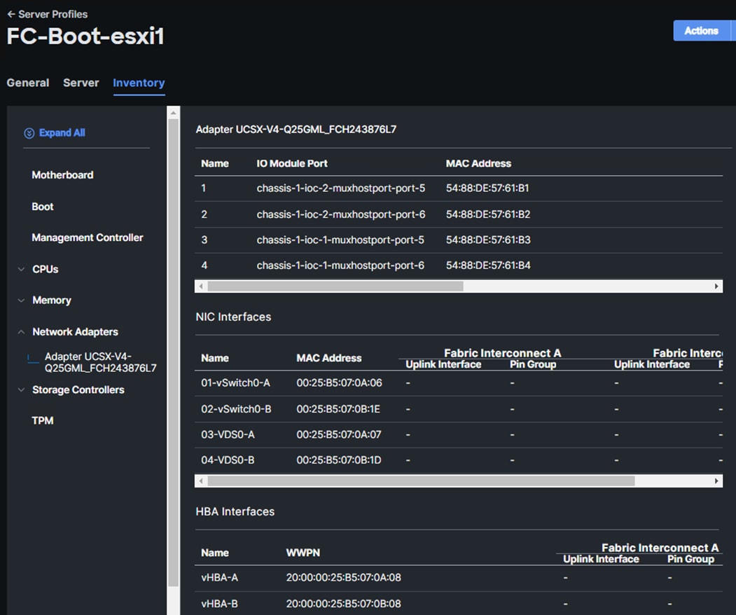
Procedure 2. Obtain the IQNs for UCS Server Profiles (required only for iSCSI configuration)
Step 1. From Cisco Intersight, go to: CONFIGURE > Pools > [IQN Pool Name] > Usage and find the IQN information for various ESXi servers:
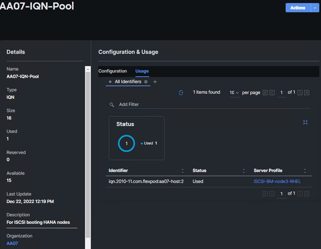
Procedure 3. Create Initiator Groups for FC Storage Access
Step 1. Run the following command on the NetApp Cluster Management Console to create the fcp initiator groups (igroups):
lun igroup create –vserver <infra-data-svm> –igroup <igroup-name> –protocol fcp –ostype vmware –initiator <vm-host-wwpna>, <vm-host-wwpnb>
Step 2. To access boot LUNs, the following FCP igroups for individual hosts are created:
lun igroup create –vserver AA07-Infra-SVM –igroup aa07-FCP-esxi2 –protocol fcp –ostype vmware –initiator 20:00:00:25:b5:07:0a:09, 20:00:00:25:b5:07:0b:09
lun igroup create –vserver AA07-Infra-SVM –igroup aa07-FCP-esxi3 –protocol fcp –ostype vmware –initiator 20:00:00:25:b5:07:0a:0a, 20:00:00:25:b5:07:0b:0a
lun igroup create –vserver AA07-Infra-SVM –igroup aa07-FCP-bm-rhel –protocol fcp –ostype linux –initiator 20:00:00:25:b5:07:0a:01, 20:00:00:25:b5:07:0b:01
lun igroup create –vserver AA07-Infra-SVM –igroup aa07-FCP-bm-sles –protocol fcp –ostype linux –initiator 20:00:00:25:b5:07:0a:02, 20:00:00:25:b5:07:0b:02
Step 3. To view and verify the FC igroups just created, run the following command:
AA07-A400::> lun igroup show -vserver Infra-SVM -protocol fcp
Vserver Igroup Protocol OS Type Initiators
--------- ------------ -------- -------- ------------------------------------
AA07-Infra-SVM aa07-FCP-esxi1
fcp vmware 20:00:00:25:b5:07:0a:08
20:00:00:25:b5:07:0b:08
AA07-Infra-SVM aa07-FCP-esxi2
fcp vmware 20:00:00:25:b5:07:0a:09
20:00:00:25:b5:07:0b:09
AA07-Infra-SVM aa07-FCP-esxi3
fcp vmware 20:00:00:25:b5:07:0a:0a
20:00:00:25:b5:07:0b:0a
AA07-Infra-SVM aa07-FCP-bm-rhel
fcp linux 20:00:00:25:b5:07:0a:01
20:00:00:25:b5:07:0b:01
AA07-Infra-SVM aa07-FCP-bm-sles
fcp linux 20:00:00:25:b5:07:0a:02
20:00:00:25:b5:07:0b:02
--------- ------------ -------- -------- ------------------------------------
5 entries were displayed.
Procedure 4. Create Initiator Groups for iSCSI Storage Access
Step 1. Run the following command on NetApp Cluster Management Console to create iscsi initiator groups (igroups):
lun igroup create –vserver <infra-svm> –igroup <igroup-name> –protocol iscsi –ostype linux –initiator <host-iqn>
Step 2. The following commands were issued for setting up ISCSI initiator groups.
lun igroup create –vserver AA07-Infra-SVM –igroup aa07-ISCSI-bm-node3-rhel -ISCSI –protocol iscsi –ostype linux -initiator iqn.2010-11.com.flexpod:aa07-host:2
Step 3. To view and verify the igroups just created, run the following command:
AA07-A400::> lun igroup show -vserver Infra-SVM -protocol iscsi
Vserver Igroup Protocol OS Type Initiators
--------- ------------ -------- -------- ------------------------------------
Infra-SVM aa07-ISCSI-bm-node3-rhel
iscsi linux iqn.2010-11.com.flexpod:aa07-host:2
1 entry were displayed.
Procedure 1. Map Boot LUNs to FCP igroups (required only for FC configuration)
Step 1. Map the boot LUNs to FC igroups, by running the following commands on NetApp cluster management console:
lun mapping create –vserver <infra-data-svm> –path <lun-path> –igroup <igroup-name> –lun-id 0
lun mapping create –vserver AA07-Infra-SVM –path /vol/server_boot/aa07-FCP-esxi1-boot –igroup aa07-FCP-esxi1 –lun-id 0
lun mapping create –vserver AA07-Infra-SVM –path /vol/server_boot/aa07-FCP-esxi2-boot –igroup aa07-FCP-esxi2 –lun-id 0
lun mapping create –vserver AA07-Infra-SVM –path /vol/server_boot/aa07-FCP-esxi3-boot –igroup aa07-FCP-esxi3 –lun-id 0
lun mapping create –vserver AA07-Infra-SVM –path /vol/server_boot/aa07-FCP-bm-rhel-boot –igroup aa07-FCP-bm-rhel –lun-id 0
lun mapping create –vserver Infra-SVM –path /vol/bm_boot/aa07-FCP-bm-sles-boot –igroup aa07-FCP-bm-sles –lun-id 0
Step 2. To verify the mapping was setup correctly, run the following command:
lun mapping show -vserver <infra-svm> -protocol fcp
AA07-A400::> lun mapping show -vserver AA07-Infra-SVM -protocol fcp
Vserver Path Igroup LUN ID Protocol
---------- ---------------------------------------- ------- ------ --------
AA07-Infra-SVM /vol/server_boot/aa07-FCP-esxi1-boot aa07-FCP-esxi1
0 fcp
AA07-Infra-SVM /vol/server_boot/aa07-FCP-esxi2-boot aa07-FCP-esxi2
0 fcp
AA07-Infra-SVM /vol/server_boot/aa07-FCP-esxi3-boot aa07-FCP-esxi3
0 fcp
AA07-Infra-SVM /vol/server_boot/aa07-FCP-bm-rhel-boot aa07-FCP-bm-rhel
0 fcp
AA07-Infra-SVM /vol/server_boot/aa07-FCP-bm-sles-boot aa07-FCP-bm-sles
0 fcp
5 entries were displayed.
Procedure 2. Map Boot LUNs to ISCSI igroups (required only for iSCSI configuration)
Step 1. Map the boot LUNs to ISCSI igroups, by running the following commands on NetApp cluster management console:
lun mapping create –vserver <infra-data-svm> –path <lun-path> –igroup <igroup-name> –lun-id 0
lun mapping create –vserver AA07-Infra-SVM –path /vol/server_boot/aa07-ISCSI-bm-rhel-boot –igroup aa07-ISCSI-bm-node3-rhel –lun-id 0
Step 2. To verify the mapping was setup correctly, run the following command:
lun mapping show -vserver <infra-data-svm> -protocol iscsi
AA07-A400::> lun mapping show -vserver AA07-Infra-SVM -protocol iscsi
Vserver Path Igroup LUN ID Protocol
---------- ---------------------------------------- ------- ------ --------
AA07-Infra-SVM /vol/server_boot/aa07-ISCSI-bm-rhel-boot aa07-ISCSI-bm-node3-rhel
0 iscsi
1 entry were displayed.
This chapter contains the following:
● Download ESXi 7.0U3i from VMware
● Access Cisco Intersight and Launch KVM with vMedia
● Set up VMware ESXi Installation
● Set up Management Networking for ESXi Hosts
● Install Cisco VIC Drivers and NetApp NFS Plug-in for VAAI
● FlexPod VMware ESXi Manual Configuration
● FlexPod VMware vSphere Distributed Switch (vDS)
● Configure vSphere Cluster Services
● Enable EVC on the VMware Cluster
This section provides detailed instructions for installing VMware ESXi 7.0U3i in a FlexPod environment. On successful completion of these steps, multiple ESXi hosts will be provisioned and ready to be added to VMware vCenter.
Several methods exist for installing ESXi in a VMware environment. These procedures focus on how to use the built-in keyboard, video, mouse (KVM) console and virtual media features in Cisco Intersight to map remote installation media to individual servers.
Download ESXi 7.0U3i from VMware
Procedure 1. Download VMware ESXi ISO
Step 1. Click the following link: Cisco Custom Image for ESXi 7.0 U3 Install CD.
Note: You will need a VMware user id and password on vmware.com to download this software.
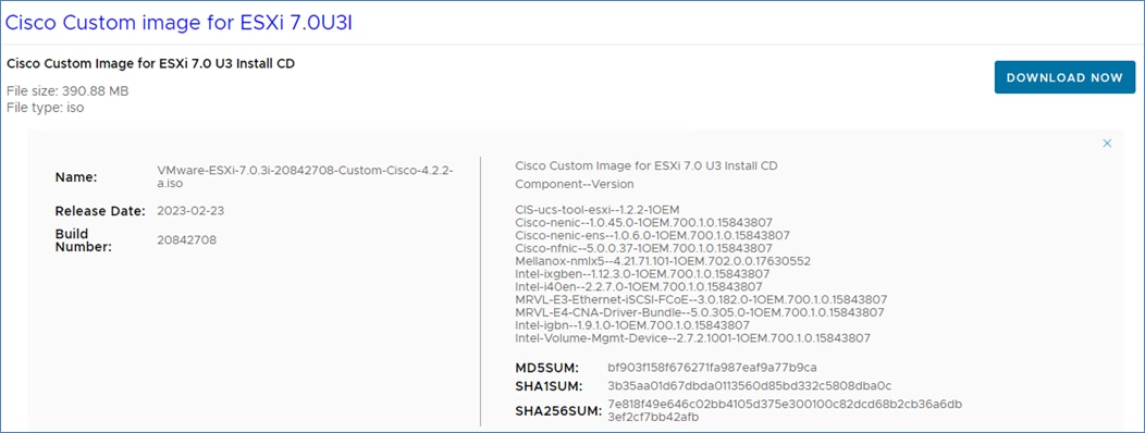
Step 2. Download the .iso file.
Access Cisco Intersight and Launch KVM with vMedia
The Cisco Intersight KVM enables the administrators to begin the installation of the operating system (OS) through remote media. It is necessary to log into the Cisco Intersight to access KVM.
Procedure 1. Log into Cisco Intersight and Access KVM
Step 1. Log into Cisco Intersight.
Step 2. From the main menu, select Infrastructure Service > Servers.
Step 3. Find the server with the desired server profile assigned and click “…” to see more options.
Step 4. Click Launch vKVM.
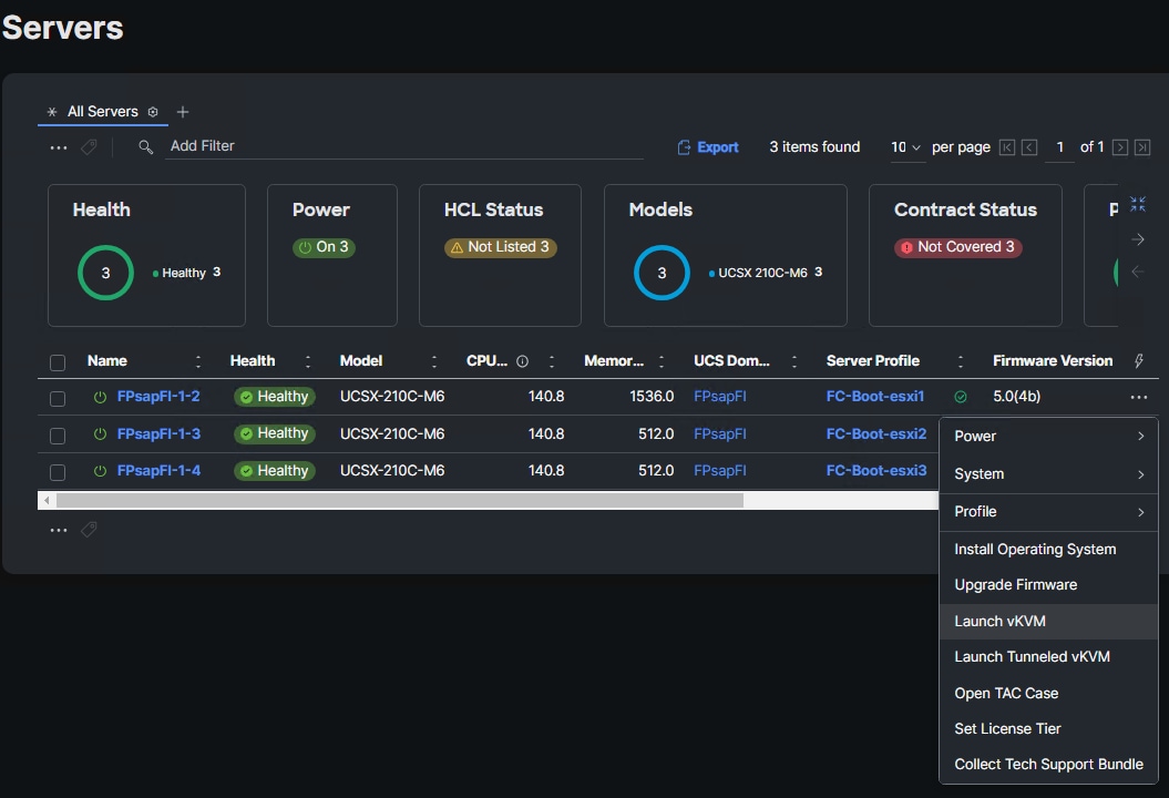
Note: Since the Cisco Custom ISO image will be mapped to the vKVM, it is important to use the standard vKVM and not the Tunneled vKVM. Make sure the Cisco Intersight interface is being run from a subnet that has direct access to the subnet on which the CIMC IPs are provisioned.
Step 5. Follow the prompts to ignore certificate workings (if any) and launch the HTML5 KVM console.
Step 6. Repeat steps 1 - 5 to launch the HTML5 KVM console for all the ESXi servers.
Set up VMware ESXi Installation
Procedure 1. Prepare the Server for the OS Installation
Note: Follow these steps on each ESXi host.
Step 1. In the KVM window, click Virtual Media > vKVM-Mapped vDVD.
Step 2. Browse and select the ESXi installer ISO image file downloaded in the last in Procedure 1 above (VMware-ESXi-7.0.3i-20842708-Custom-Cisco-4.2.2-a.iso).
Step 3. Click Map Drive.
Step 4. Click Power > Reset System and Confirm to reboot the Server if the server is showing shell prompt. If the server is shutdown, click Power > Power On System.
Step 5. Monitor the server boot process in the KVM. The server should find the boot LUNs and begin to load the ESXi installer.
Note: If the ESXi installer fails to load because the software certificates cannot be validated, reset the server, and when prompted, press F2 to go into BIOS and set the system time and date to current. The ESXi installer should load properly.
Procedure 1. Install VMware ESXi onto the bootable LUN of the UCS Servers
Note: Follow these steps on each host.
Step 1. After the ESXi installer is finished loading (from the last step), press Enter to continue with the installation.
Step 2. Read and accept the end-user license agreement (EULA). Press F11 to accept and continue.
Note: It may be necessary to map function keys as User Defined Macros under the Macros menu in the KVM console.
Step 3. Select the NetApp boot LUN that was previously set up as the installation disk for ESXi and press Enter to continue with the installation.
Step 4. Select the appropriate keyboard layout and press Enter.
Step 5. Enter and confirm the root password and press Enter.
Step 6. The installer issues a warning that the selected disk will be repartitioned. Press F11 to continue with the installation.
Step 7. After the installation is complete, press Enter to reboot the server. The ISO will be unmapped automatically.
Set up Management Networking for ESXi Hosts
Procedure 1. Add the Management Network for each VMware Host
Note: This is required for managing the host. To configure ESXi host with access to the management network, follow these steps on each ESXi host.
Step 1. After the server has finished rebooting, in the UCS KVM console, press F2 to customize VMware ESXi.
Step 2. Log in as root, enter the password set during installation, and press Enter to log in.
Step 3. Use the down arrow key to select Troubleshooting Options and press Enter.
Step 4. Select Enable ESXi Shell and press Enter.
Step 5. Select Enable SSH and press Enter.
Step 6. Press Esc to exit the Troubleshooting Options menu.
Step 7. Select the Configure Management Network option and press Enter.
Step 8. Select Network Adapters and press Enter. Ensure the vmnic numbers align with the numbers under the Hardware Label (for example, vmnic0 and 00-vSwitch0-A). If these numbers do not align, note which vmnics are assigned to which vNICs (indicated under Hardware Label).
Note: In previous FlexPod CVDs, vmnic1 was selected at this stage as the second adapter in vSwitch0. It is important not to select vmnic1 at this stage. If using the Ansible configuration, if vmnic1 is selected here, the Ansible playbook will fail.
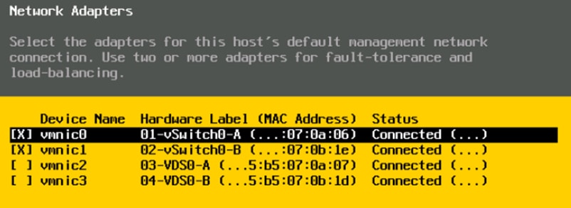
Step 9. Press Enter.
Step 10. In the UCS Configuration portion of this document, the VLAN 2 was set as the native VLAN on the 00-vSwitch0-A and 01-vSwitch0-B vNICs. Because of this, set the IB-MGMT VLAN.
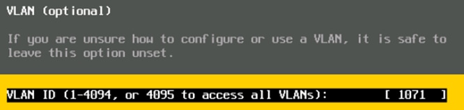
Step 11. Select IPv4 Configuration and press Enter.
Note: When using DHCP to set the ESXi host networking configuration, setting up a manual IP address is not required.
Step 12. Select the Set static IPv4 address and network configuration option by using the arrow keys and space bar.
Step 13. Under IPv4 Address, enter the IP address for managing the ESXi host.
Step 14. Under Subnet Mask, enter the subnet mask.
Step 15. Under Default Gateway, enter the default gateway.
Step 16. Press Enter to accept the changes to the IP configuration.
Step 17. Select the IPv6 Configuration option and press Enter.
Step 18. Using the spacebar, select Disable IPv6 (restart required) and press Enter.
Step 19. Select the DNS Configuration option and press Enter.
Note: If the IP address is configured manually, the DNS information must be provided.
Step 20. Using the spacebar, select Use the following DNS server addresses and hostname:
● Under Primary DNS Server, enter the IP address of the primary DNS server.
● Optional: Under Alternate DNS Server, enter the IP address of the secondary DNS server.
● Under Hostname, enter the fully qualified domain name (FQDN) for the ESXi host.
● Press Enter to accept the changes to the DNS configuration.
● Press Esc to exit the Configure Management Network submenu.
● Press Y to confirm the changes and reboot the ESXi host.
Install Cisco VIC Drivers and NetApp NFS Plug-in for VAAI
Procedure 1. Download Drivers to the Management Workstation
Consult the Cisco UCS Hardware Compatibility List and the NetApp Interoperability Matrix Tool to determine latest supported combinations of firmware and software based on the compute in use.
Step 1. Download and extract where necessary the following drivers to the Management Workstation
● VMware ESXi 7.0 nfnic 5.0.0.37 Driver for Cisco VIC Adapters – Cisco-nfnic_5.0.0.37-1OEM.700.1.0.15843807_20873938.zip – extracted from the downloaded zip
● VMware ESXi 7.0 nenic 1.0.45.0 Driver for Cisco VIC Adapters – Cisco-nenic_1.0.45.0-1OEM.700.1.0.15843807_20904742.zip – extracted from the downloaded zip
● NetApp NFS Plug-in for VMware VAAI 2.0.1 – NetAppNasPlugin2.0.1.zip extracted from the downloaded zip.
Procedure 2. Install VMware Drivers and the NetApp NFS Plug-in for VMware VAAI on the ESXi hosts and Setup
Step 1. Using an SCP program, copy the two bundles referenced above to the /tmp directory on each ESXi host.
Step 2. SSH to each VMware ESXi host and log in as root.
Step 3. Run the following commands on each host:
esxcli software component apply -d /tmp/Cisco-nfnic_5.0.0.37-1OEM.700.1.0.15843807_20873938.zip
esxcli software component apply -d /tmp/Cisco-nenic_1.0.45.0-1OEM.700.1.0.15843807_20904742.zip
esxcli software component apply -d /tmp/Broadcom-lsi-mr3_7.720.04.00-1OEM.700.1.0.15843807_19476191.zip
esxcli software vib install -d /tmp/NetAppNasPlugin2.0.1.zip
esxcfg-advcfg -s 0 /Misc/HppManageDegradedPaths
reboot
Step 4. After reboot, SSH back into each host and use the following commands to ensure the correct version are installed:
esxcli software component list | grep nfnic
esxcli software component list | grep nenic
esxcli software component list | grep lsi-mr3
esxcli software vib list | grep NetApp
esxcfg-advcfg -g /Misc/HppManageDegradedPaths
FlexPod VMware ESXi Manual Configuration
FlexPod VMware ESXi Configuration for the first ESXi Host
Procedure 1. Log into the First ESXi Host using the VMware Host Client
Step 1. Open a web browser and navigate to the first ESXi server’s management IP address.
Step 2. Enter root as the User name.
Step 3. Enter the <root password>.
Step 4. Click Log into connect.
Step 5. Decide whether to join the VMware Customer Experience Improvement Program or not and click OK.
Procedure 2. Set Up iSCSI VMkernel Ports and Virtual Switch (required only for iSCSI boot configuration)
Note: This configuration section only applies to iSCSI ESXi hosts.
Step 1. From the Web Navigator, click Networking.
Step 2. In the center pane, select the Virtual switches tab.
Step 3. Highlight the iScsiBootvSwitch line.
Step 4. Click Edit settings.
Step 5. Change the MTU to 9000.
Step 6. Click Save to save the changes to iScsiBootvSwitch.
Step 7. Select Add standard virtual switch.
Step 8. Name the switch vSwitch1.
Step 9. Change the MTU to 9000.
Step 10. From the drop-down list select vmnic5 for Uplink 1.
Step 11. Select Add to add vSwitch1.
Step 12. In the center pane, select the VMkernel NICs tab.
Step 13. Highlight the iScsiBootPG line.
Step 14. Click Edit settings.
Step 15. Change the MTU to 9000.
Step 16. Expand IPv4 Settings and enter a unique IP address in the Infra-iSCSI-A subnet but outside of the Cisco Intersight iSCSI-IP-Pool-A.
Note: It is recommended to enter a unique IP address for this VMkernel port to avoid any issues related to IP Pool reassignments in Cisco UCS.
Step 17. Click Save to save the changes to iScsiBootPG VMkernel NIC.
Step 18. Select Add VMkernel NIC.
Step 19. For New port group, enter iScsiBootPG-B.
Step 20. For Virtual switch, from the drop-down list select vSwitch1.
Step 21. Change the MTU to 9000.
Step 22. For IPv4 settings, select Static.
Step 23. Expand IPv4 Settings and enter a unique IP address and Subnet mask in the Infra-iSCSI-B subnet but outside of the Cisco UCS iSCSI-IP-Pool-B.
Step 24. Click Create to complete creating the VMkernel NIC.
Step 25. In the center pane, select the Port groups tab.
Step 26. Highlight the iScsiBootPG line.
Step 27. Click Edit settings.
Step 28. Change the Name to iScsiBootPG-A.
Step 29. Click Save to complete editing the port group name.
Step 30. Select Storage, then in the center pane select the Adapters tab.
Step 31. Select Software iSCSI to configure software iSCSI for the host.
Step 32. In the Configure iSCSI window, click Add dynamic target.
Step 33. Select Click to add address and enter the IP address of iscsi-lif-01a from Infra-SVM. Press Enter.
Step 34. Repeat steps 32-33 to add the IP addresses for iscsi-lif-02a, iscsi-lif-01b, and iscsi-lif-02b.
Step 35. Click Save configuration.
Step 36. Click Software iSCSI again open configuration window for iSCSI software adapter.
Step 37. Verify that four static targets and four dynamic targets are listed for the host.
Step 38. Click Cancel to close the window.
Procedure 3. Set Up VMkernel Ports and Virtual Switch
Step 1. From the Host Client Navigator, select Networking.
Step 2. In the center pane, select the Virtual switches tab.
Step 3. Highlight the vSwitch0 line.
Step 4. Click Edit settings.
Step 5. Change the MTU to 9000.
Step 6. Click Add uplink.
Step 7. If vmnic1 is not selected for Uplink 2, then use the pulldown to select vmnic1.
Step 8. Expand NIC teaming.
Step 9. In the Failover order section, if the status of the vmnic1 is not Active, select vmnic1 and click Mark active.
Step 10. Verify that vmnic1 now has a status of Active.
Step 11. Click Save.
Step 12. Click Networking, then click the Port groups tab.
Step 13. Right-click VM Network and select Edit settings.
Step 14. Name the port group IB-MGMT Network and leave the VLAN ID set to <IB-MGMT_VLAN>.
Note: (Optional) The IB-MGMT VLAN can be set as the native VLAN for the vSwitch0 vNIC templates and the port group’s VLAN ID can be set to 0
Step 15. Click Save to finalize the edits for the IB-MGMT Network port group.
Step 16. Click the VMkernel NICs tab.
Step 17. Click Add VMkernel NIC.
Step 18. For New port group, enter VMkernel-Infra-NFS.
Step 19. For Virtual switch, select vSwitch0.
Step 20. Enter <infra-nfs-vlan-id> (for example, 1075) for the VLAN ID.
Step 21. Change the MTU to 9000.
Step 22. Select Static IPv4 settings and expand IPv4 settings.
Step 23. Enter the NFS IP address and netmask for this ESXi host.
Step 24. Leave TCP/IP stack set at Default TCP/IP stack and do not select any of the Services.
Step 25. Click Create.
Step 26. Click the Virtual Switches tab, then select vSwitch0. The properties for vSwitch0 should be similar to the following screenshot:
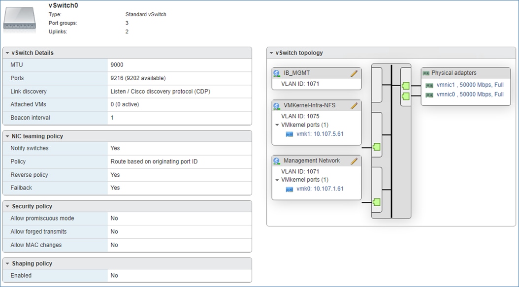
Step 1. From the Web Navigator, click Storage.
Step 2. Click the Datastores tab.
Step 3. Click New Datastore to add a new datastore.
Step 4. In the New datastore popup, select Mount NFS datastore and click Next.
Step 5. Enter infra_datastore_1 for the datastore name and IP address of the NetApp nfs-lif-02 LIF for the NFS server. Enter /infra_datastore_1 for the NFS share. Select the NFS version. Click Next.
AA07-A400::> network interface show -vserver Infra-SVM -data-protocol nfs
Logical Status Network Current Current Is
Vserver Interface Admin/Oper Address/Mask Node Port Home
----------- ---------- ---------- ------------------ ------------- ------- ----
Infra-SVM
nfs-lif-01 up/up xx.xxx.5.1/24 AA07-A400-01 a0a-1075
true
nfs-lif-02 up/up xx.xxx.5.2/24 AA07-A400-02 a0a-1075
true
2 entries were displayed.
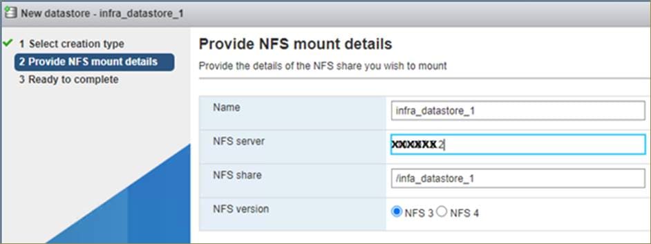
Step 6. Review the information and click Finish. The datastore will appear in the datastore list.
Step 7. Click New Datastore to add a new datastore.
Step 8. In the New datastore popup, select Mount NFS datastore and click Next.
Step 9. Enter infra_swap for the datastore name and IP address of the NetApp nfs-lif-01 LIF for the NFS server. Enter /infra_swap for the NFS share. Select the NFS version. Click Next.
Step 10. Click Finish. The datastore will appear in the datastore list.
Step 11. Click New Datastore to add a new datastore.
Step 12. In the New datastore popup, select Mount NFS datastore and click Next.
Step 13. Enter vCLS for the datastore name and IP address of the NetApp nfs-lif-01 LIF for the NFS server. Enter /vCLS for the NFS share. Select the NFS version. Click Next.
Step 14. Click Finish. The datastore should now appear in the datastore list.
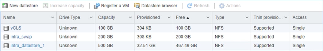
Procedure 5. Configure NTP Servers
Step 1. From the Web Navigator, click Manage.
Step 2. Click System > Time & date.
Step 3. Click Edit NTP Settings.
Step 4. Select Use Network Time Protocol (enable NTP client).
Step 5. From the drop-down list select Start and stop with host.
Step 6. Enter the NTP server IP addresses in the NTP servers.
Step 7. Click Save to save the configuration changes.
Step 8. Click the Services tab.
Step 9. Right-click ntpd and click Start.
Step 10. System > Time & date will display “Running” for the NTP service status.
Procedure 6. Configure Host Power Policy on the First ESXi Host
Note: Implementation of this policy is recommended in Performance Tuning Guide for Cisco UCS M6 Servers: https://www.cisco.com/c/en/us/products/collateral/servers-unified-computing/ucs-b-series-blade-servers/performance-tuning-guide-ucs-m6-servers.html under references recommending to "Set the power policy to High Performance” for maximum VMware ESXi performance. This policy can be adjusted based on your requirements.
Step 1. From the ESXi vcenter Web Navigator, click Manage.
Step 2. Click Hardware > Power Management.
Step 3. Click Change policy.
Step 4. Select High performance and click OK.
VMware vCenter 7.0U3l
The procedures in the following sections provide detailed instructions for installing the VMware vCenter 7.0U3l Server Appliance in a FlexPod environment.
Procedure 1. Download vCenter 7.0U3L from VMware
Step 1. Click this link: https://customerconnect.vmware.com/downloads/details?downloadGroup=VC70U3L&productId=974&rPId=95488 and download the VMware-VCSA-all-7.0.3-21477706.iso.
Step 2. You will need a VMware user id and password on vmware.com to download this software.
Procedure 2. Install the VMware vCenter Server Appliance
Note: The VCSA deployment consists of 2 stages: installation and configuration.
Step 1. Locate and copy the VMware-VCSA-all-7.0.3-21477706.iso file to the desktop of the management workstation. This ISO is for the VMware vSphere 7.0 U3l vCenter Server Appliance.
Step 2. Mount the ISO image as a disk on the management workstation. For example, with the Mount command in Windows Server 2012 and above.
Step 3. In the mounted disk directory, navigate to the vcsa-ui-installer > win32 directory and double-click installer.exe. The vCenter Server Appliance Installer wizard appears.
Step 4. Click Install to start the vCenter Server Appliance deployment wizard.
Step 5. Click NEXT in the Introduction section.
Step 6. Read and accept the license agreement and click NEXT.
Step 7. In the vCenter Server deployment target window, enter the FQDN or IP address of the destination host, User name and Password. Click NEXT.
Note: Installing vCenter on a separate, existing management infrastructure vCenter is recommended. If a separate management infrastructure is not available, select the recently configured first ESXi host as an installation target. The recently configured ESXi host is shown in this deployment.
Step 8. Click YES to accept the certificate.
Step 9. In the Set up vCenter Server VM section, enter the Appliance VM name and password details. Click NEXT.
Step 10. In the Select deployment size section, select the Deployment size and Storage size. For example, select “Small” and “Default.” Click NEXT.
Step 11. Select the datastore (for example, infra_datastore_1) for storage. Click NEXT.
Step 12. In the Network Settings section, configure the following settings:
a. Select a Network: (for example, IB-MGMT Network)
Note: When the vCenter is running on the FlexPod, it is important that the vCenter VM stay on the IB-MGMT Network on vSwitch0 and not moved to a vDS. If vCenter is moved to a vDS and the virtual environment is completely shut down and then brought back up, trying to bring up vCenter on a different host than the one it was running on before the shutdown will cause problems with the network connectivity. With the vDS, for a virtual machine to move from one host to another, vCenter must be up and running to coordinate the move of the virtual ports on the vDS. If vCenter is down, the port move on the vDS cannot occur correctly. Moving vCenter to a different host on vSwitch0 does not require vCenter to already be up and running.
b. IP version: IPV4
c. IP assignment: static
d. FQDN: <vcenter-fqdn>
e. IP address: <vcenter-ip>
f. Subnet mask or prefix length: <vcenter-subnet-mask>
g. Default gateway: <vcenter-gateway>
h. DNS Servers: <dns-server1>,<dns-server2>
Step 13. Click NEXT.
Step 14. Review all values and click FINISH to complete the installation.
Note: The vCenter Server appliance installation will take a few minutes to complete.
Step 15. When Stage 1, Deploy vCenter Server, is complete, click CONTINUE to proceed with stage 2.
Step 16. Click NEXT.
Step 17. In the vCenter Server configuration window, configure these settings:
a. Time Synchronization Mode: Synchronize time with NTP servers.
b. NTP Servers: NTP server IP addresses from IB-MGMT VLAN.
c. SSH access: Enabled.
Step 18. Click NEXT.
Step 19. Complete the SSO configuration as shown below (or according to your organization’s security policies):
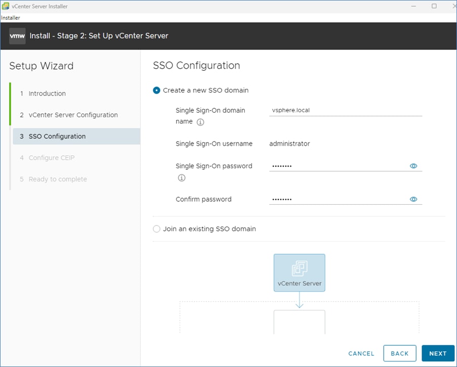
Step 20. Click NEXT.
Step 21. Decide whether to join VMware’s Customer Experience Improvement Program (CEIP).
Step 22. Click NEXT.
Step 23. Review the configuration and click FINISH.
Step 24. Click OK.
Note: The vCenter Server setup will take a few minutes to complete and Install – Stage 2 with show Complete.
Step 25. Click CLOSE. Eject or unmount the VCSA installer ISO.
Procedure 3. Verify vCenter CPU Settings
Note: If a vCenter deployment size of Small or larger was selected in the vCenter setup, it is possible that the VCSA’s CPU setup does not match the Cisco UCS server CPU hardware configuration. Cisco UCS X210c M6 and B200 M6 servers are 2-socket servers. During this validation, the Small deployment size was selected and vCenter was setup on a separate management PoD’s VMWare cluster with Cisco UCS B200 M6 nodes.
Step 1. Open a web browser on the management workstation and navigate to the vCenter or ESXi server where the vCenter appliance was deployed and login.
Step 2. Click the vCenter VM, right-click and click Edit settings.
Step 3. In the Edit settings window, expand CPU and check the value of Sockets.
Step 4. If the number of Sockets match the server configuration, click Cancel.
Step 5. If the number of Sockets does not match the server configuration, it will need to be adjusted. Right-click the vCenter VM and click Guest OS > Shut down. Click Yes on the confirmation.
Step 6. When vCenter is shut down, right-click the vCenter VM and click Edit settings.
Step 7. In the Edit settings window, expand CPU and change the Cores per Socket value to make the Sockets value equal to the server configuration.
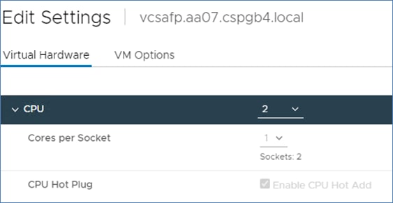
Step 8. Click Save.
Step 9. Right-click the vCenter VM and click Power > Power on. Wait approximately 10 minutes for vCenter to come up.
Procedure 4. Setup VMware vCenter Server
Step 1. Using a web browser, navigate to https://<vcenter-ip-address>:5480 and navigate the security screens.
Step 2. Log into the VMware vCenter Server Management interface as root with the root password set in the vCenter installation.
Step 3. Click Time.
Step 4. Click EDIT.
Step 5. Select the appropriate Time zone and click SAVE.
Step 6. select Administration.
Step 7. According to your Security Policy, adjust the settings for the root user and password.
Step 8. Click Update.
Step 9. Follow the prompts to stage and install any available vCenter updates.
Step 10. Click root > Logout to logout of the Appliance Management interface.
Step 11. Using a web browser, navigate to https://<vcenter-fqdn> and navigate through security screens.
Note: With VMware vCenter 7.0 and above, you must use the vCenter FQDN.
Step 12. Select LAUNCH VSPHERE CLIENT (HTML5).
Note: The VMware vSphere HTML5 Client is the only option in vSphere 7. All the old clients have been deprecated.
Step 13. Log in using the Single Sign-On username (administrator@vsphere.local) and password created during the vCenter installation. Dismiss the Licensing warning.
vCenter - Initial Configuration
Procedure 1. Configure vCenter
Step 1. Click ACTIONS > New Datacenter.
Step 2. In the Datacenter name field, type FlexPod-DC.
Step 3. Click OK.
Step 4. Expand the vCenter.
Step 5. Right-click the datacenter FlexPod-DC in the list. Click New Cluster…
Step 6. Provide a name for the cluster (for example, AA07-cluster).
Step 7. Turn on DRS and vSphere HA.
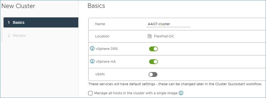
Step 8. Click NEXT and then click FINISH to create the new cluster.
Step 9. Right-click the cluster and click Settings.
Step 10. Click Configuration > General in the list and click EDIT to the right of General.
Step 11. Select Datastore specified by host for the Swap file location and click OK.
Step 12. Right-click the cluster and select Add Hosts.
Step 13. In the IP address or FQDN field, enter either the IP address or the FQDN of the first VMware ESXi host. Enter root as the Username and the root password.
Step 14. For all other configured ESXi hosts, click ADD HOST. Enter either the IP address or the FQDN of the host being added. You can either select “Use the same credentials for all hosts” or enter root and the host root password. Repeat this to add all hosts.
Step 15. Click NEXT.
Step 16. In the Security Alert window, select the host(s) and click OK.
Step 17. Verify the Host summary information and click NEXT.
Step 18. Ignore the warnings about the host being moved to Maintenance Mode and click FINISH to complete adding the host(s) to the cluster.
Note: The added ESXi host(s) will have warnings that the ESXi Shell and SSH have been enabled. These warnings can be suppressed. The host will also have a TPM Encryption Key Recovery alert that can be reset to green.
Step 19. For any hosts that are in Maintenance Mode, right-click the host and select Maintenance Mode > Exit Maintenance Mode.
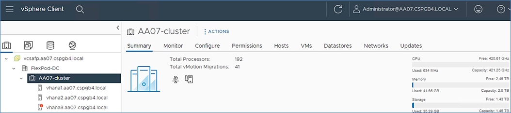
Step 20. In the list, right-click the added ESXi host(s) and click Settings.
Step 21. Under Virtual Machines, click Swap File location.
Step 22. Click EDIT.
Step 23. Select infra_swap and click OK.
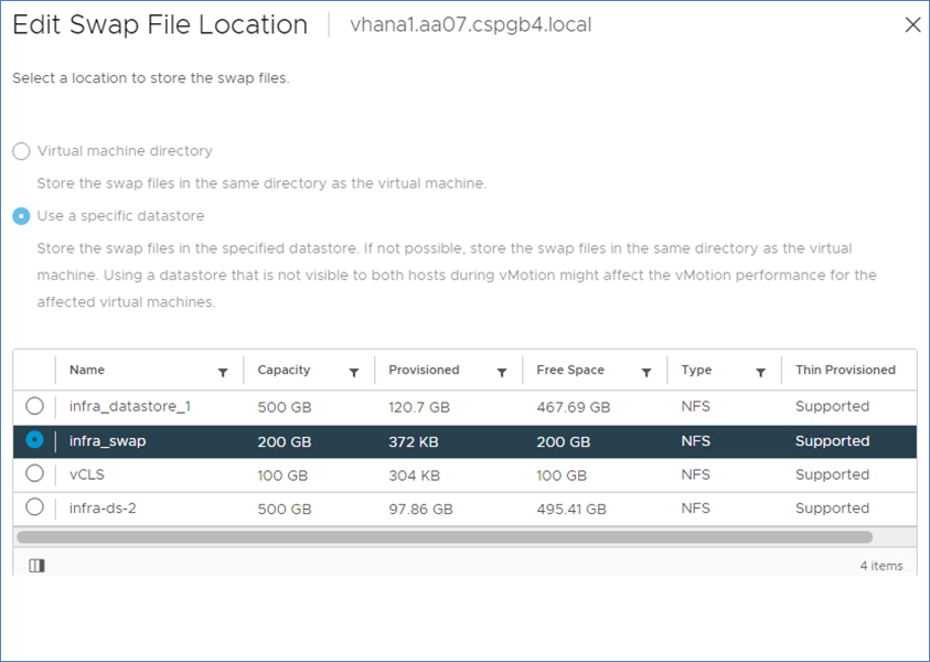
Step 24. Repeat steps 20-23 to set the swap file location for each configured ESXi host.
Step 25. Right-click the cluster and select Settings. Under vSphere Cluster Services, select Datastores. Click ADD. Select the vCLS datastore and click ADD.
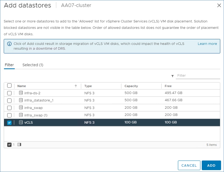
Step 26. Select the first ESXi host. Under Configure > Storage, click Storage Devices. Make sure the NetApp Fibre Channel Disk LUN 0 or NetApp iSCSI Disk LUN 0 is selected.
Step 27. Click the Paths tab.
Step 28. Ensure that 4 paths appear, two of which should have the status Active (I/O). The output below shows the paths for a FC LUN.
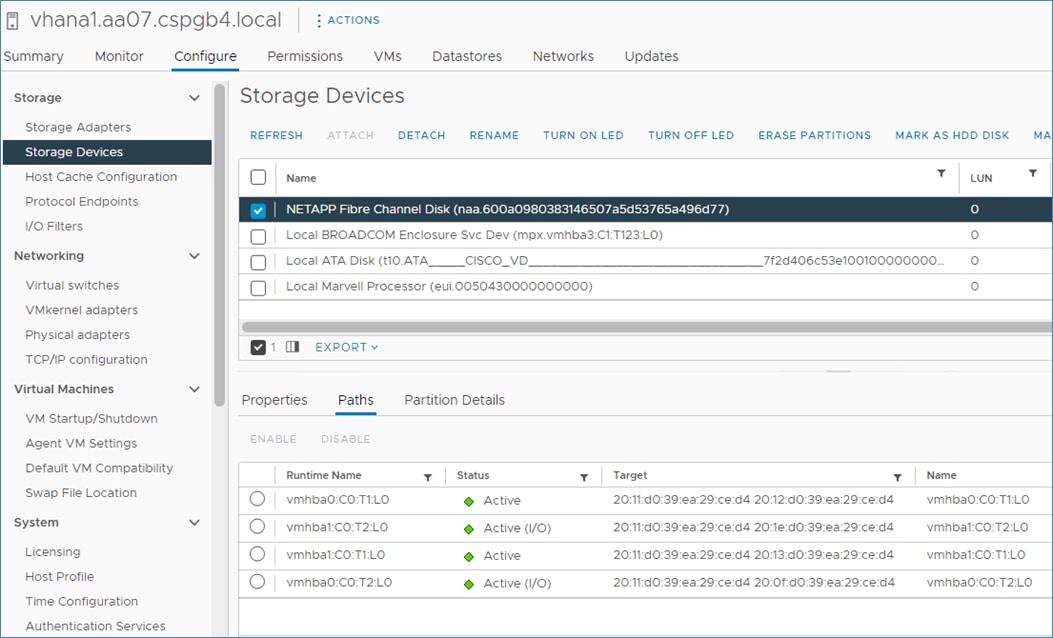
Step 29. Repeat steps 26-28 for all configured ESXi hosts.
FlexPod VMware vSphere Distributed Switch (vDS)
This section provides detailed procedures for setting up VMware vDS in vCenter. Based on the VLAN configuration in Intersight, a vMotion, and a VM-Traffic/Application traffic port group will be added to the vDS. Any additional VLAN-based port groups added to the vDS would require changes in Intersight, the Cisco Nexus 9K switches, and possibly the NetApp storage cluster.
In this document, the infrastructure ESXi management VMkernel ports, the In-Band management interfaces including the vCenter management interface, and the infrastructure NFS VMkernel ports are left on vSwitch0 to facilitate bringing the virtual environment back up in the event it needs to be completely shut down. The vMotion VMkernel ports are provisioned on the vDS to allow for future QoS support. The vMotion port group is also pinned to Cisco UCS Fabric B and pinning configuration in vDS ensures consistency across all ESXi hosts.
Procedure 1. Configure the VMware vDS in vCenter
Step 1. After logging into the VMware vSphere HTML5 Client, select Inventory.
Step 2. Click ![]() , to go to Networking.
, to go to Networking.
Step 3. Expand the vCenter and right-click the FlexPod-DC datacenter and click Distributed Switch > New Distributed Switch.
Step 4. Give the Distributed Switch a descriptive name (for example, AA07_App_DVS) and click NEXT.
Step 5. Make sure version 7.0.3 – ESXi 7.0.3 and later is selected and click NEXT.
Step 6. Change the Number of uplinks to 2. If VMware Network I/O Control is to be used for Quality of Service, leave Network I/O Control Enabled. Otherwise, Disable Network I/O Control. Enter VM-Traffic-HANA-Data for the Port group name. Click NEXT.
Step 7. Review the information and click FINISH to complete creating the vDS.
Step 8. Expand the FlexPod-DC datacenter and the newly created vDS. Click the newly created vDS.
Step 9. Right-click the VM-Traffic-HANA-Data port group and click Edit Settings.
Step 10. Select VLAN.
Step 11. Select VLAN for VLAN type and enter the VM-Traffic VLAN ID (for example, 1077). Click OK.
Step 12. Right-click the created vDS > Distributed Port Group > New Distributed Port Group. Create port groups corresponding to the use-case requirements.
Note: In the validation setup, VM-Traffic-HANA-Log [VLAN 1076], VM-Traffic-HANA-Shared [VLAN 1077], VM-Traffic-HANA-Appserver [VLAN 75], VM-Traffic-HANA-Replication [VLAN 1073] were configured.
Step 13. Right-click the vDS and click Settings > Edit Settings.
Step 14. In Edit Settings, click the Advanced tab.
Step 15. Change the MTU to 9000. The Discovery Protocol can optionally be changed to Link Layer Discovery Protocol and the Operation to Both. Click OK.
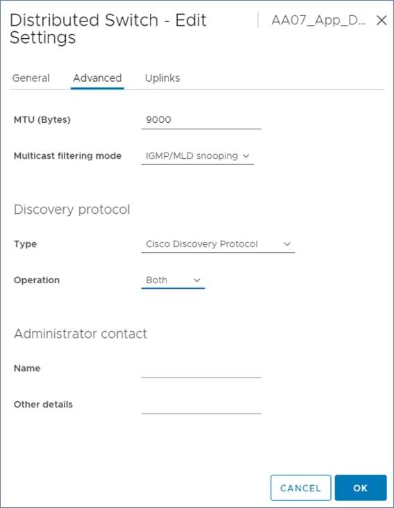
Step 16. To create the vMotion port group, right-click the vDS and select Distributed Port Group > New Distributed Port Group.
Step 17. Enter vMotion as the name and click NEXT.
Step 18. Set the VLAN type to VLAN, enter the VLAN ID used for vMotion (for example, 1072), check the box for Customize default policies configuration, and click NEXT.
Step 19. Leave the Security options set to Reject and click NEXT.
Step 20. Leave the Ingress and Egress traffic shaping options as Disabled and click NEXT.
Step 21. From the list of Active uplinks, select Uplink 1 and double-click MOVE DOWN to place Uplink 1 in the list of Standby uplinks. This will pin all vMotion traffic to UCS Fabric Interconnect B, except when a failure occurs.
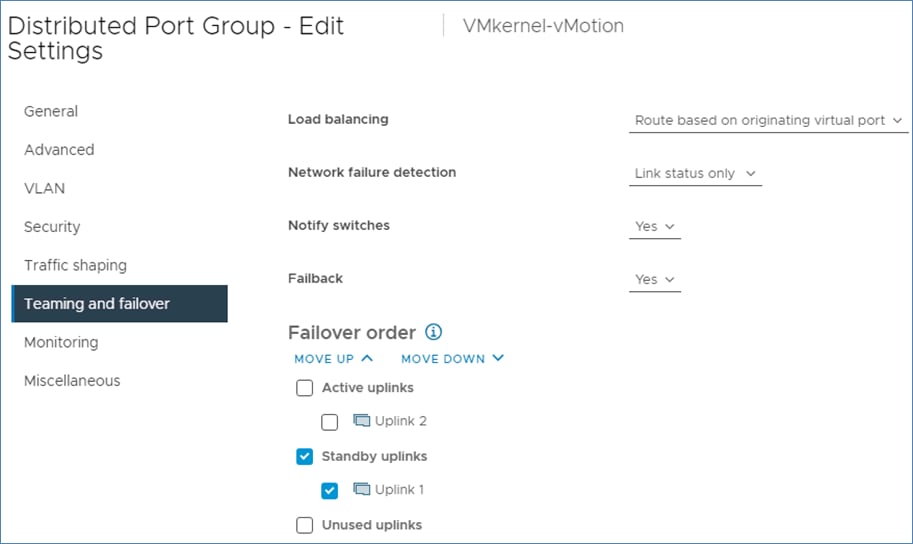
Step 22. Click NEXT.
Step 23. Leave NetFlow disabled and click NEXT.
Step 24. Leave Block all ports set as No and click NEXT.
Step 25. Confirm the options and click FINISH to create the port group.
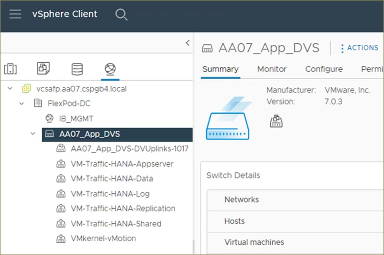
Step 26. Right-click the vDS and click Add and Manage Hosts.
Step 27. Make sure Add hosts is selected and click NEXT.
Step 28. Click SELECT ALL to select all ESXi hosts. Click NEXT.
Step 29. If all hosts had alignment in the ESXi console screen between vmnic numbers and vNIC numbers, leave Adapters on all hosts selected. In vmnic2, from the drop-down list select Uplink 1. In vmnic3, from the drop-down list select Uplink 2. Click NEXT. If the vmnic numbers and vNIC numbers did not align, select Adapters per host and select vDS uplinks individually on each host.
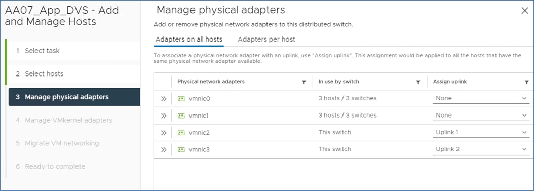
Note: It is important to assign the uplinks as shown above. This allows the port groups to be pinned to the appropriate Cisco UCS Fabric.
Step 30. Do not migrate any VMkernel ports and click NEXT.
Step 31. Do not migrate any virtual machine networking ports. Click NEXT.
Step 32. Click FINISH to complete adding the ESXi host to the vDS.
Step 33. Select Hosts and Clusters and select the first ESXi host. Click the Configure tab.
Step 34. Under Networking, select VMkernel adapters.
Step 35. Click ADD NETWORKING.
Step 36. In the Add Networking window, ensure that VMkernel Network Adapter is selected and click NEXT.
Step 37. Ensure that Select an existing network is selected and click BROWSE.
Step 38. Select vMotion and click OK.
Step 39. Click NEXT.
Step 40. From the MTU drop-down list, select Custom and ensure the MTU is set to 9000.
Step 41. From the TCP/IP stack drop-down list, select vMotion. Click NEXT.
Step 42. Select Use static IPv4 settings and fill in the IPv4 address and Subnet mask for the first ESXi host’s vMotion IPv4 address and Subnet mask. Click NEXT.
Step 43. Review the information and click FINISH to complete adding the vMotion VMkernel port.
Step 44. Repeat steps 33-43 for all other configured ESXi hosts.
Configure vSphere Cluster Services
The vSphere Cluster Services (vCLS) is a new feature introduced with vSphere 7 U1. It ensures cluster services such as vSphere DRS and vSphere HA are available to maintain the resources and health of the workloads like SAP HANA running in the cluster independent of the vCenter Server instance availability.
The vSphere Clustering service uses agent VMs to maintain cluster services health and up to three VMs are created when adding hosts to the cluster.
vSphere Clustering Service Deployment Guidelines for SAP HANA Landscapes
As of SAP Note 2937606 and subsequent guidelines per SAP HANA on vSphere 7 Update 1 – vSphere Cluster Service (vCLS), SAP HANA production VMs should not get co-deployed with any other workload VMs on the same vSphere ESXi host and NUMA node sharing between SAP HANA and non-HANA is not allowed. Because of these guidelines and due to the mandatory and automated installation process of vSphere Clustering Service, it is required to ensure vCLS VMs will get migrated to hosts that do not run SAP HANA production-level VMs.
This can be achieved by configuring a vSphere Clustering Service VM anti-affinity policy. This policy describes a relationship between VMs that have been assigned a special anti-affinity tag (for example a tag named SAP HANA) and vSphere Clustering service system VMs.
If this tag is assigned to SAP HANA VMs, the policy discourages placement of vSphere Clustering Service VMs and SAP HANA VMs on the same host. This assures that vSphere Clustering Service VMs and SAP HANA VMs do not get co-deployed.
Procedure 1. Create Category and Tag
Step 1. In the vSphere client menu select Tags & Custom Attributes.
Step 2. In the TAGS screen click Add Tag.
Step 3. Create a new category (PRODUCTION) and enter a category description. Click Create.
Step 4. Select the category. Enter a tag name (SAP HANA) and a description. Click Create.
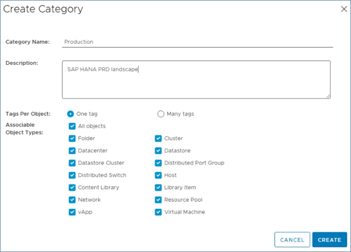
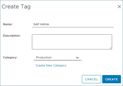
Procedure 2. Create Anti-Affinity policy for vCLS
Step 1. In the vSphere client menu select Policies and Profiles.
Step 2. Select Compute Policies and click Add.
Step 3. From the Policy type drop-down list, select Anti-affinity with vSphere Cluster Service.
Step 4. Enter a policy Name and policy Description.
Step 5. From the drop-down lists, select category Production and tag SAP HANA, click Create.
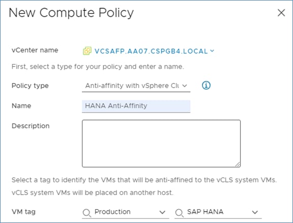
Enable EVC on the VMware Cluster
In cluster environments with mixed compute nodes and CPU architectures it is required to ensure CPU compatibility when planning to move VMs between hosts of different architectures. In addition, special attention requires the number of sockets, cores and main memory which must be adapted manually if required. Other cluster features such as vSphere DRS and vSphere HA are fully compatible with EVC.
Procedure 1. Enable EVC for Intel Hosts
Step 1. Navigate to Inventory > Hosts and Clusters and select the cluster object (AA07-cluster).
Step 2. Click the Configure tab, select Configuration - VMware EVC. Click Edit.
Step 3. Select Enable EVC for Intel Hosts.
Step 4. Select CPU mode Intel Ice Lake generation.
Step 5. Make sure the Compatibility box displays Validation succeeded. Click OK.
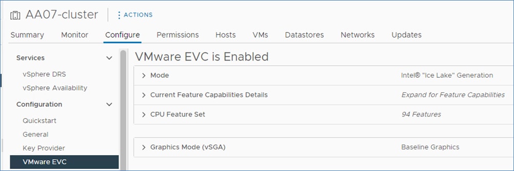
Procedure 2. VMware ESXi 7.0 U3 TPM Attestation
Note: If your Cisco UCS servers have Trusted Platform Module (TPM) 2.0 modules installed, the TPM can provide assurance that ESXi has booted with UEFI Secure Boot enabled and using only digitally signed code. In the Cisco UCS Configuration section of this document, UEFI secure boot was enabled in the boot order policy. A server can boot with UEFI Secure Boot with or without a TPM 2.0 module. If it has a TPM, VMware vCenter can attest that the server booted with UEFI Secure Boot. To verify the VMware ESXi 7.0 U3 TPM Attestation, follow these steps:
Step 1. For Cisco UCS servers that have TPM 2.0 modules installed, TPM Attestation can be verified in the vSphere HTML5 Client.
Step 2. In the vCenter HTML5 Interface, under Hosts and Clusters select the cluster.
Step 3. Click the Monitor tab.
Step 4. Click Monitor > Security from the menu. The Attestation status will show the status of the TPM. If no TPM module is installed, the status will display N/A.:
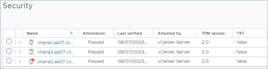
Note: It may be necessary to disconnect and reconnect or reboot a host from vCenter to get it to pass attestation the first time.
Prepare the VM Host for SAP HANA
This chapter contains the following:
● Overview
● Deployment Options with VMware Virtualization
● SAP HANA on VMware vSphere Configuration and Sizing Guidelines
● SAP HANA Virtual Machine Configuration
The VMware vSphere 7.0 virtual machine or the bare-metal node must be prepared to host the SAP HANA installation.
SAP HANA on Cisco UCS M6 2-socket nodes can be deployed as scale-up system.
Deployment Options with VMware Virtualization
The supported SAP HANA start release is SAP HANA 1.0 SPS 12 Revision 122.19; SAP HANA 2.0 is recommended. Make sure to review SAP Note 2937606 - SAP HANA on VMware vSphere 7.0 in production for the most current updates. Intel Ice Lake processors TDIv5 Model 2 sockets, requires vSphere 7.0 U3 (>= U3c).
Besides SAP HANA, most SAP applications and databases can get virtualized and are fully supported for production workloads either on dedicated vSphere hosts or running consolidated side by side.
Table 21. Overview of SAP HANA on vSphere Deployment Options
| Host Socket Size |
Certified Configuration |
Virtual SAP HANA VM Sizes |
| 2-socket |
Cisco UCS M6 Ice Lake <= 4 TiB, max. 160 CPU threads |
Scale-Up: 0.5, 1 and 2-socket wide VMs Scale-Out: N/A Min: 8 vCPUs and 128 GiB vRAM Max: 160 vCPUs and 4 TiB vRAM Up to 4 VMs per 2-socket host |
SAP HANA on VMware vSphere Configuration and Sizing Guidelines
SAP HANA must be sized according to the existing SAP HANA sizing guidelines and VMware recommendations. The sizing report provides information about the required CPU size (SAP Application Performance Standard (SAPS)), memory and storage resources.
The general sizing recommendation is to scale-up first; for production environments CPU and memory over-commitment must be avoided. Depending on workload-based sizing results (SAP Note 2779240 - Workload-based sizing for virtualized environments) a deviation from the existing core-to-memory ratio might be possible for virtualized HANA.
VMware vSphere uses datastores to store virtual disks. Datastores provide an abstraction of the storage layer that hides the physical attributes of the storage devices from the virtual machines. The datastores types applicable for FlexPod, such as VMFS, NFS or vSphere virtual volumes (vVOL) are fully supported with SAP HANA deployments.
All SAP HANA instances do have an operating system, local SAP, database log, database data, and shared SAP volume. The storage sizing calculation of these volumes is based on the overall amount of memory the node is configured with.
The storage layout and sizing follow the guidelines per SAP Note 1900823. While the OS disk/partition is carved out from an already presented NFS datastore [infra_datastore_1], it is recommended to directly mount the NFS volumes for /usr/sap partition, /hana/data, /hana/log and /hana/shared filesystems inside the host VM.
SAP HANA Virtual Machine Configuration
With the vHANA example requirements above (full-socket CPU, 1.5 TB RAM) the deployment procedure of a single SAP HANA instance can be executed as follows on a Cisco UCS X120C M6 compute node:
Procedure 1. Create an SAP HANA virtual machine
Step 1. The new vHANA instance will use the available NFS datastore created earlier, which will keep the VMDKs of the OS.
Step 2. Navigate to Inventory > Hosts and Clusters.
Step 3. Right-click the cluster object (FlexPod-DC) and select New Virtual Machine.
Step 4. Select the creation type Create a new virtual machine and click Next.
Step 5. Enter a virtual machine name (for example, vhanar86 or vhanasle154 depending on the OS) and click Next.
Step 6. Select the compute resource to run the VM. Expand the cluster object and select the ESXi host. Click Next.
Step 7. Select the datastore (infra_datastore_1) and click Next.
Step 8. Keep the ESXi 7.0 U2 and later compatibility and click Next.
Step 9. Select Linux as Guest OS Family and either the Guest OS version Red Hat Enterprise Linux 8 or SUSE Linux Enterprise 15. based on the desired OS. Click Next.
Step 10. From the drop-down list, enter 64 vCPUs.
Step 11. Expand the CPU entry and select 32 cores which changes the number of sockets to two. CPU Hot Plug stays disabled.
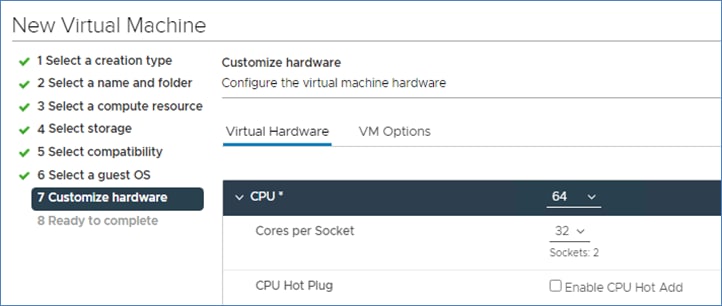
Step 12. Enter the necessary memory [for example, 1536 GB]. Expand the field and checkmark Reserve all guest memory (all locked).
Step 13. In the new hard disk field, enter 80 GB. Expand the field and change disk provisioning to thin provision.
Step 14. From the Location drop-down list, select Browse to change the location to infra_datastore_1.
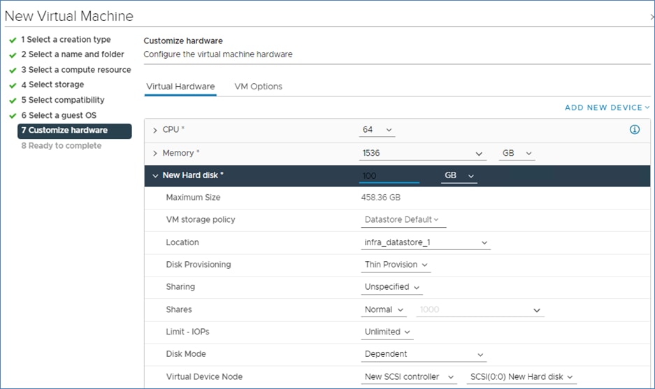
Step 15. For the New Network first select the IB_MGMT network.
Step 16. Click Add New Device and from the drop-down list, Network - Network Adapter.
Step 17. From the New Network drop-down list, select Browse and AppServer.
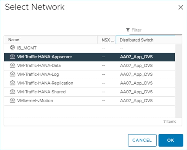
Step 18. Repeat steps 16 and 17 to add all required SAP HANA related networks.
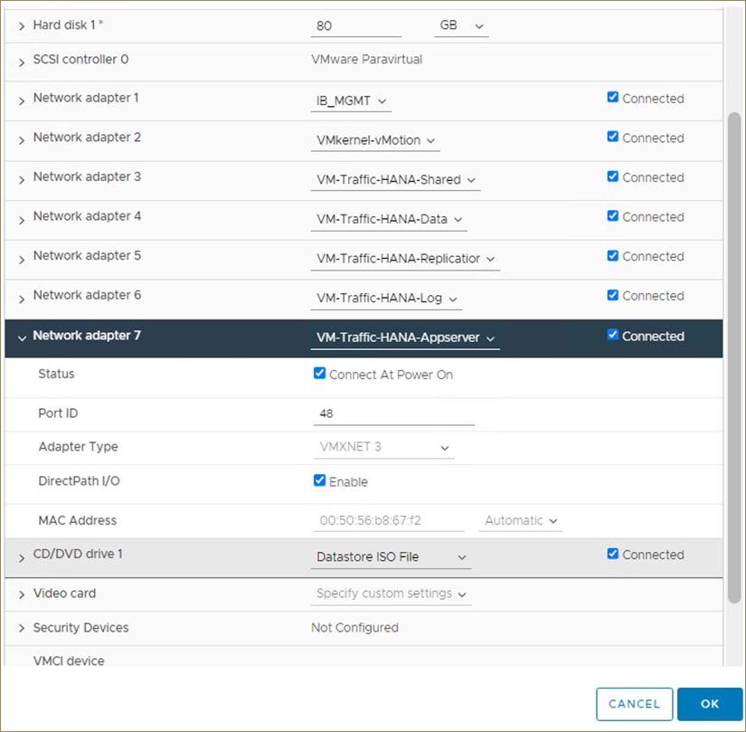
Step 19. Change the New CD/DVD drive to Datastore ISO File and select your OS installation image.
Step 20. Select the checkmark field Connect, then click Next.
Step 21. Review the configuration details and click Finish.
Procedure 2. vSphere Clustering Service deployment
According to the SAP requirements, non-SAP HANA VMs should not run on the same NUMA node where a productive SAP HANA VM is already running. Additionally, no NUMA node sharing is allowed between SAP HANA and non-HANA virtual machines.
Step 1. Navigate to Inventory > Hosts and Clusters.
Step 2. Expand the cluster object (FlexPod-DC) and select the virtual machine.
Step 3. In the Summary - Tags field select Assign Tag.
Step 4. Select the SAP HANA tag and click Assign.
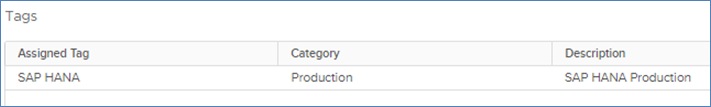
Procedure 3. Operating System Installation
The Linux operating system installations follows the Red Hat or SUSE specific installation guides:
● Red Hat Enterprise Linux 8 - Configuring RHEL 8 for SAP HANA 2 installation
● SUSE Linux Enterprise Server for SAP Applications Guide
Step 1. Select the Power On button to start the virtual machine.
Step 2. Launch the web console.
Step 3. Follow the installation wizard. Detailed information on the installation process is available in the installation guides.
Step 4. Confirm the network adapter MAC address from the virtual machine Summary tab in the VM Hardware - Network Adapter status page to ensure to configure the correct network adapter.
Step 5. When the installation finishes, reboot the machine.
Step 6. From the virtual machine overview in the vSphere client, select Install VMware Tools.
Step 7. Click Actions > Guest OS - Install VMware Tools.
As soon as the vhanar86 virtual machine is up, vSphere will check the VM is compliant with the Anti-Affinity policy created before and move the vCLS virtual machine away from the host.
Step 8. Review the status in the vhanar86 Virtual Machine Summary tab.
Procedure 4. Operating System configuration
This procedure explains of to manually define the file systems before the operating system configuration and SAP HANA installation.
Step 1. SSH into the virtual machine as root.
Step 2. Find the available disks using the command:
[root@vhanar86 ~]# lsblk
NAME MAJ:MIN RM SIZE RO TYPE MOUNTPOINT
sda 8:0 0 50G 0 disk
├─sda1 8:1 0 600M 0 part /boot/efi
├─sda2 8:2 0 1G 0 part /boot
└─sda3 8:3 0 48.4G 0 part
├─rhel-root 253:0 0 44.4G 0 lvm /
└─rhel-swap 253:1 0 4G 0 lvm [SWAP]
sr0 11:0 1 10.7G 0 rom
Step 3. Make sure to configure the recommended operating system settings according to below SAP notes and apply the latest security patches to the new system before installing SAP HANA.
● SAP Note 277299 - Red Hat Enterprise Linux 8.x: Installation and Configuration
● SAP Note 2777782 - SAP HANA DB: Recommended OS Settings for RHEL 8
● SAP Note 2578899 - SUSE Linux Enterprise Server 15: Installation Note
● SAP Note 2684254 - SAP HANA DB: Recommended OS Settings for SLES 15 / SLES for SAP Applications 15
Storage Configuration – NetApp ONTAP SAP HANA Persistence Storage Setup
This chapter contains the following:
● Manual NetApp ONTAP Storage Configuration Part 3
This configuration requires information from both the server profiles and NetApp storage system.
In this chapter, the storage is configured to provide the SAP HANA Persistence, primarily SAP HANA Data, Log and Shared filesystems.
Note: For bare-metal installations, the recommendation is to leverage FC protocol for SAP HANA Data and Log mounts and NFS v3/4.1 for SAP HANA Shared filesystem. For virtualized SAP HANA, NFS v3/4.1 filesystems for SAP HANA Data, Log and Shared are direct mounted inside the VM host,
Manual NetApp ONTAP Storage Configuration Part 3
Procedure 1. Configure SVM for HANA
Table 22 and Figure 8 describe the HANA SVM together with all the required storage objects (volumes, export-policies, and LIFs) and Figure 9 summarizes the Broadcast Domains and VLANs created so far and the ones to be created.
Figure 8. Overview of SAP HANA SVM Components
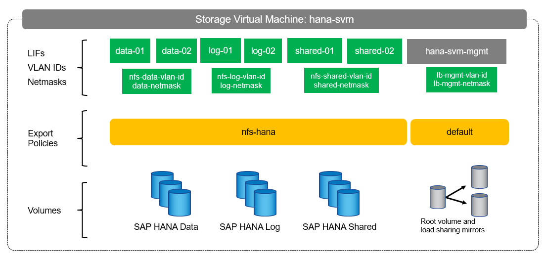
Figure 9. Summary of Broadcast Domains and VLANs
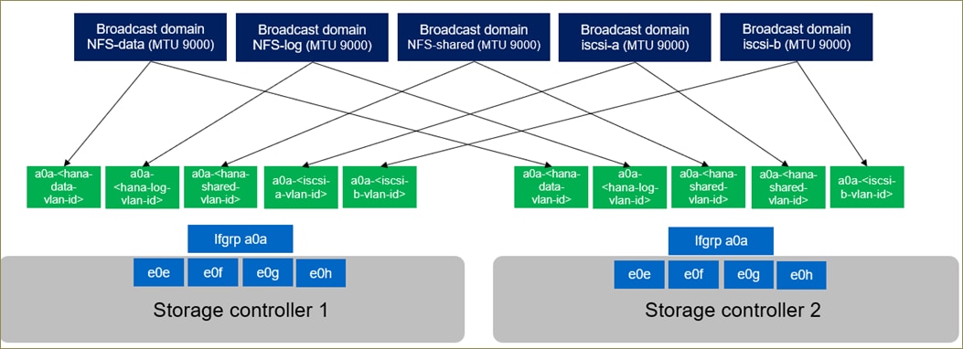
Table 22. ONTAP Software Parameter for HANA SVM
| Cluster Detail |
Cluster Detail Value |
| HANA SVM management IP / netmask |
<hana-svm-ip> / <hana-svm-netmask> |
| HANA SVM default gateway |
<hana-svm-gateway> |
| NFS Shared CIDR / netmask |
<shared-cidr> / <shared-netmask> |
| NFS Shared VLAN ID |
<nfs-shared-vlan-id> |
| NFS shared LIF node 1 IP |
<node01-shared_lif01-ip> |
| NFS shared LIF node 2 IP |
<node02-shared_lif02-ip> |
| HANA Data CIDR / netmask |
<data-cidr> / <data-netmask> |
| HANA Data VLAN ID |
<nfs-data-vlan-id> |
| Data LIF node 1 IP |
<node01-data_lif01-ip> |
| Data LIF node 2 IP |
<node02-data_lif02-ip> |
| HANA Log CIDR / netmask |
<data-cidr> / <log-netmask> |
| HANA Log VLAN ID |
<nfs-log-vlan-id> |
| Log LIF node 1 IP |
<node01-log_lif01-ip> |
| Log LIF node 2 IP |
<node02-log_lif02-ip> |
Procedure 2. Create an SVM for SAP HANA Volumes
Step 1. Run the vserver create command.
vserver create –vserver AA07-HANA-SVM –rootvolume hana_rootvol –aggregate aggr1_2 –rootvolume-security-style unix
Step 2. Select the SVM data protocols to configure, keeping NFS and FCP.
vserver remove-protocols –vserver AA07-HANA-SVM -protocols cifs,iscsi,nvme
Step 3. Add the two data aggregates to the AA07-HANA-SVM aggregate list.
vserver modify –vserver AA07-HANA-SVM –aggr-list aggr1_1,aggr1_2,aggr2_1,aggr2_2
Step 4. Disable any QOS policy at the vserver level
vserver modify -vserver AA07-HANA-SVM -qos-policy-group none
Step 5. Enable and run the NFS protocol in the Infra-SVM.
nfs create -vserver AA07-HANA-SVM -udp disabled -v3 enabled -v4.1 enabled -vstorage enabled
Step 6. Enable a large NFS transfer size.
set advanced
vserver nfs modify -vserver AA07-HANA-SVM -tcp-max-xfer-size 1048576
set admin
Step 7. Set the group ID of the user root to 0.
vserver services unix-user modify -vserver AA07-HANA-SVM -user root -primary-gid 0
Procedure 3. Create Load-Sharing Mirrors of a SVM Root Volume
Step 1. Create a volume to be the load-sharing mirror of the HANA SVM root volume on each node.
volume create –vserver AA07-HANA-SVM –volume hana_rootvol_m01 –aggregate aggr2_1 –size 1GB –type DP
volume create –vserver AA07-HANA-SVM –volume hana_rootvol_m02 –aggregate aggr2_2 –size 1GB –type DP
Step 2. Create the mirroring relationships.
snapmirror create –source-path AA07-HANA-SVM:hana_rootvol –destination-path AA07-HANA-SVM:hana_rootvol_m01 –type LS -schedule 5min
snapmirror create –source-path AA07-HANA-SVM:hana_rootvol –destination-path AA07-HANA-SVM:hana_rootvol_m02 –type LS -schedule 5min
Step 3. Initialize the mirroring relationship.
snapmirror initialize-ls-set –source-path AA07-HANA-SVM:hana_rootvol
Procedure 4. Create NFS Export Policies for the Root Volumes
Step 1. Create a new rule for the infrastructure NFS subnet in the default export policy.
vserver export-policy rule create –vserver AA07-HANA-SVM -policyname default –ruleindex 1 -clientmatch 0.0.0.0/0 -rorule sys –rwrule sys -superuser sys –allow-suid true –protocol nfs
Step 2. Assign the FlexPod export policy to the infrastructure SVM root volume.
volume modify –vserver AA07-HANA-SVM –volume hana_rootvol –policy default
Procedure 5. Add HANA SVM Management Interface and Administrator
This procedure adds the HANA SVM administrator and SVM administration LIF in the out-of-band management network.
Step 1. Run the following commands:
network interface create –vserver AA07-HANA-SVM –lif svm-mgmt -service-policy default-management –home-node <st-node02> -home-port -home-port a0a-<ib-mgmt-vlan-id> –address <hana-svm-ip> -netmask <hana-svm-netmask> -status-admin up –failover-policy broadcast-domain-wide –auto-revert true
Step 2. Create a default route to allow the SVM management interface to reach the outside world.
network route create –vserver AA07-HANA-SVM -destination 0.0.0.0/0 –gateway <hana-svm-gateway>
Step 3. Set a password for the SVM vsadmin user and unlock the user.
security login password –username vsadmin –vserver AA07-HANA-SVM
Enter a new password: <password>
Enter it again: <password>
security login unlock –username vsadmin –vserver AA07-HANA-SVM
Procedure 6. Create Broadcast Domain for SAP HANA Shared filesystem Network
Step 1. To create an NFS shared broadcast domain with a maximum transmission unit (MTU) of 9000, run the following commands in NetApp ONTAP:
network port broadcast-domain create -broadcast-domain AA07-NFS-shared -mtu 9000
Procedure 7. Optional, only needed in IP-only solution or virtualized SAP HANA scenario - Create Broadcast Domains for SAP HANA data and log filesystem networks
Step 1. To create an NFS data broadcast domain with a maximum transmission unit (MTU) of 9000, run the following commands in NetApp ONTAP:
network port broadcast-domain create -broadcast-domain AA07-NFS-data -mtu 9000
Step 2. To create an NFS log broadcast domain with a maximum transmission unit (MTU) of 9000, run the following commands in NetApp ONTAP:
network port broadcast-domain create -broadcast-domain AA07-NFS-log -mtu 9000
Procedure 8. Create VLAN ports for SAP HANA shared filesystem network
Step 1. Create the NFS VLAN ports and add them to the NFS shared broadcast domain.
network port vlan create –node <st-node01> -vlan-name a0a-<hana-shared-vlan-id>
network port vlan create –node <st-node02> -vlan-name a0a-<hana-shared-vlan-id>
network port broadcast-domain add-ports -broadcast-domain AA07-NFS-shared -ports <st-node01>:a0a-<hana-shared-vlan-id>,<st-node02>:a0a-<hana-shared-vlan-id>
Procedure 9. Optional, only needed in IP-only solution or virtualized SAP HANA scenario - Create VLAN ports for SAP HANA data and log filesystem networks
Step 1. Create the NFS VLAN ports and add them to the NFS shared broadcast domain.
network port vlan create –node <st-node01> -vlan-name a0a-<hana-data-vlan-id>
network port vlan create –node <st-node02> -vlan-name a0a-<hana-data-vlan-id>
network port broadcast-domain add-ports -broadcast-domain AA07-NFS-data -ports <st-node01>:a0a-<hana-data-vlan-id>,<st-node02>:a0a-<hana-data-vlan-id>
Step 2. Create the NFS VLAN ports and add them to the NFS shared broadcast domain.
network port vlan create –node <st-node01> -vlan-name a0a-<hana-log-vlan-id>
network port vlan create –node <st-node02> -vlan-name a0a-<hana-log-vlan-id>
network port broadcast-domain add-ports -broadcast-domain AA07-NFS-log -ports <st-node01>:a0a-<hana-log-vlan-id>,<st-node02>:a0a-<hana-log-vlan-id>
Procedure 10. Create Export Policies for the HANA SVM
Step 1. Create a new export policy for the Hana shared, HANA data, and log subnet.
vserver export-policy create -vserver AA07-HANA-SVM -policyname nfs-hana
Step 2. Create a rule for this policy.
vserver export-policy rule create -vserver AA07-HANA-SVM -policyname nfs-hana -clientmatch <data-cidr>,<log-cidr>,<shared-cidr> -rorule sys -rwrule sys -allow-suid true -allow-dev true -ruleindex 1 -protocol nfs -superuser sys
Procedure 11. Create NFS LIF for SAP HANA Shared
Step 1. To create the NFS LIFs for SAP HANA data, run the following commands:
network interface create -vserver AA07-HANA-SVM -lif shared-01 -data-protocol nfs -home-node <st-node01> -home-port a0a-<hana-shared-vlan-id> –address <node01-shared_lif01-ip> -netmask <shared-netmask> -status-admin up –failover-policy broadcast-domain-wide –auto-revert true
network interface create -vserver AA07-HANA-SVM -lif shared-02 -data-protocol nfs -home-node <st-node02> -home-port a0a-<hana-shared-vlan-id> –address <node02-shared_lif02-ip> -netmask <data-netmask> -status-admin up –failover-policy broadcast-domain-wide –auto-revert true
Step 2. Verification:
AA07-A400::> network interface show -vserver AA07-HANA-SVM -data-protocol nfs
Logical Status Network Current Current Is
Vserver Interface Admin/Oper Address/Mask Node Port Home
----------- ---------- ---------- ------------------ ------------- ------- ----
AA07-HANA-SVM
shared-01 up/up xx.xxx.7.1/24 AA07-A400-01 a0a-1077
true
shared-02 up/up xx.xxx.7.2/24 AA07-A400-02 a0a-1077
true
2 entries were displayed.
Procedure 12. Optional, only needed in IP/NFS-only solution and virtualized SAP HANA scenario - Create NFS LIF for SAP HANA Data and Log
Step 1. To create the NFS LIFs for SAP HANA data, run the following commands:
network interface create -vserver AA07-HANA-SVM -lif data-01 -data-protocol nfs -home-node <st-node01> -home-port a0a-<hana-data-vlan-id> –address <node01-data_lif01-ip> -netmask <data-netmask> -status-admin up -failover-policy broadcast-domain-wide –auto-revert true
network interface create -vserver AA07-HANA-SVM -lif data-02 -data-protocol nfs -home-node <st-node02> -home-port a0a-<hana-data-vlan-id> –address <node02-data_lif02-ip> -netmask <data-netmask> -status-admin up –failover-policy broadcast-domain-wide –auto-revert true
Step 2. To create the NFS LIFs for SAP HANA log, run the following commands:
network interface create -vserver AA07-HANA-SVM -lif log-01 -data-protocol nfs -home-node <st-node01> -home-port a0a-<hana-log-vlan-id> –address <node01-log_lif01-ip> -netmask <log-netmask> -status-admin up –failover-policy broadcast-domain-wide –auto-revert true
network interface create -vserver AA07-HANA-SVM -lif log-02 -data-protocol nfs -home-node <st-node02> -home-port a0a-<hana-log-vlan-id> –address <node02-log_lif02-ip> -netmask <log-netmask> -status-admin up –failover-policy broadcast-domain-wide –auto-revert true
Step 3. Verification:
AA07-A400::> network interface show -vserver AA07-HANA-SVM -data-protocol nfs
Logical Status Network Current Current Is
Vserver Interface Admin/Oper Address/Mask Node Port Home
----------- ---------- ---------- ------------------ ------------- ------- ----
AA07-HANA-SVM
shared-01 up/up xx.xxx.7.1/24 AA07-A400-01 a0a-1077
true
shared-02 up/up xx.xxx.7.2/24 AA07-A400-02 a0a-1077
true
data-01 up/up xx.xxx.4.1/24 AA07-A400-01 a0a-1074
true
data-02 up/up xx.xxx.4.2/24 AA07-A400-02 a0a-1074
true
log-01 up/up xx.xxx.6.1/24 AA07-A400-01 a0a-1076
true
log-02 up/up xx.xxx.6.2/24 AA07-A400-02 a0a-1076
true
6 entries were displayed.
Procedure 13. Create FCP LIFs to enable presenting HANA persistence LUNs to the earlier FC SAN booted bare metal SAP HANA nodes.
Step 1. To create four FCP LIFs (two on each node), run the following commands:
net interface create -vserver AA07-HANA-SVM -lif fcp_hana_2a -data-protocol fcp -home-node <st-node02> -home-port 5a
net interface create -vserver AA07-HANA-SVM -lif fcp_hana_2b -data-protocol fcp -home-node <st-node02> -home-port 5b
net interface create -vserver AA07-HANA-SVM -lif fcp_hana_1a -data-protocol fcp -home-node <st-node01> -home-port 5a
net interface create -vserver AA07-HANA-SVM -lif fcp_hana_1b -data-protocol fcp -home-node <st-node01> -home-port 5b
Step 2. Verification:
AA07-A400::> network interface show -vserver AA07-HANA-SVM -data-protocol fcp
Logical Status Network Current Current Is
Vserver Interface Admin/Oper Address/Mask Node Port Home
----------- ---------- ---------- ------------------ ------------- ------- ----
AA07-HANA-SVM
fcp_hana_1a up/up 20:10:d0:39:ea:29:ce:d4
AA07-A400-01 5a true
fcp_hana_1b up/up 20:08:d0:39:ea:29:ce:d4
AA07-A400-01 5b true
fcp_hana_2a up/up 20:09:d0:39:ea:29:ce:d4
AA07-A400-02 5a true
fcp_hana_2b up/up 20:0e:d0:39:ea:29:ce:d4
AA07-A400-02 5b true
4 entries were displayed..
Procedure 14. Create Portset
Step 1. To create a portset that includes all FCP LIFs, run the following commands:
portset create -vserver AA07-HANA-SVM -portset all_ports -protocol fcp -port-name fcp_hana_1a,fcp_hana_1b,fcp_hana_2a,fcp_hana_2b
Procedure 15. Create igroups to present HANA persistence LUNs to the previous FC SAN booted Bare Metal SAP HANA nodes
Step 1. To create igroups, run the following commands. Repeat this command by using the WWPNs of additional servers to create additional igroups for additional servers.
igroup create –vserver AA07-HANA-SVM –igroup aa07-FCP-esxi1 –protocol fcp –ostype vmware –initiator 20:00:00:25:b5:07:0a:08, 20:00:00:25:b5:07:0b:08 -portset all_ports
igroup create –vserver AA07-HANA-SVM –igroup aa07-FCP-esxi2 –protocol fcp –ostype vmware –initiator 20:00:00:25:b5:07:0a:09, 20:00:00:25:b5:07:0b:09 -portset all_ports
igroup create –vserver AA07-HANA-SVM –igroup aa07-FCP-esxi3 –protocol fcp –ostype vmware –initiator 20:00:00:25:b5:07:0a:0a, 20:00:00:25:b5:07:0b:0a -portset all_ports
igroup create –vserver AA07-HANA-SVM –igroup aa07-FCP-bm-rhel –protocol fcp –ostype linux –initiator 20:00:00:25:b5:07:0a:01, 20:00:00:25:b5:07:0b:01 -portset all_ports
igroup create –vserver AA07-HANA-SVM –igroup aa07-FCP-bm-sles –protocol fcp –ostype linux –initiator 20:00:00:25:b5:07:0a:02, 20:00:00:25:b5:07:0b:02 -portset all_ports
SAP HANA Scale-Up System Provisioning for Virtualized or IP/NFS-only Based Bare-Metal Nodes
This chapter contains the following:
● Configure SAP HANA Scale-Up Systems
● Configuration Example for a SAP HANA Scale-up System
This chapter describes the sequence of steps required to provision nodes for SAP HANA installation in the VMWare environment or IP/NFS only based setup. Starting with the storage volume configuration, OS preparation to mount the storage volumes and subsequent use-case specific preparation tasks. The underlying infrastructure configuration has already been defined in the previous sections of this document.
Note: The configuration steps are identical for ISCSi booting bare-metal servers and for VMware VM host.
Table 23 lists the required variables used in this section.
| Variable |
Value |
| IP address of LIF for SAP HANA shared (on storage node1) |
<node01-shared_lif01-ip> |
| IP address of LIF for SAP HANA shared (on storage node2) |
<node02-shared_lif02-ip> |
| IP address of LIF for SAP HANA Data (on storage node 1) |
<node01-data_lif01-ip> |
| IP address of LIF for SAP HANA Data (on storage node 2) |
<node02-data_lif02-ip> |
| IP address of LIF for SAP HANA Log (on storage node 1) |
<node01-log_lif01-ip> |
| IP address of LIF for SAP HANA Log (on storage node 2) |
<node02-log_lif02-ip> |
Each SAP HANA host, either bare-metal or VMware virtual machine, has three network interfaces connected o the storage network. One network interface each is used to mount the log volume, the data volume, and the shared volume for SAP HANA. The data and log volumes of the SAP HANA systems must be distributed to the storage nodes, as shown in Figure 10, so that a maximum of six data and six log volumes are stored on a single storage node.
The limitation of having six SAP HANA hosts per storage node is only valid for production SAP HANA systems for which the storage-performance key performance indicators defined by SAP must be fulfilled. For nonproduction SAP HANA systems, the maximum number is higher and must be determined during the sizing process.
Figure 10. Data and Log Volumes Distributed to the Storage Nodes
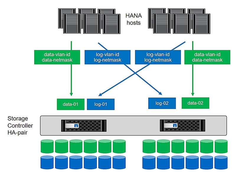
Configure SAP HANA Scale-up Systems
Figure 11 shows the volume configuration of four scale-up SAP HANA systems. The data and log volumes of each SAP HANA system are distributed to different storage controllers. For example, volume SID1_data_mnt00001 is configured on controller A, and volume SID1_log_mnt00001 is configured on controller B.
Figure 11. Four Scale-Up SAP HANA System Volume Configuration
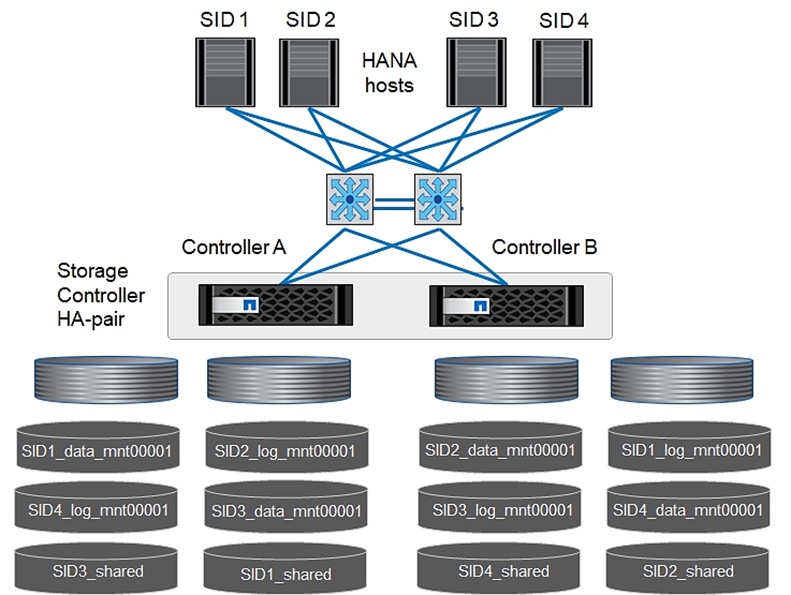
Configure a data volume, a log volume, and a volume for /hana/shared for each SAP HANA host. Table 24 lists an example configuration for scale-up SAP HANA systems.
Table 24. Volume Configuration for SAP HANA Scale-up Systems
| Purpose |
Aggregate 1 at Controller A |
Aggregate 2 at Controller A |
Aggregate 1 at Controller B |
Aggregate 2 at Controller B |
| Data, log, and shared volumes for system SID1 |
Data volume: SID1_data_mnt00001 |
Shared volume: SID1_shared |
|
Log volume: SID1_log_mnt00001 |
| Data, log, and shared volumes for system SID2 |
|
Log volume: SID2_log_mnt00001 |
Data volume: SID2_data_mnt00001 |
Shared volume: SID2_shared |
| Data, log, and shared volumes for system SID3 |
Shared volume: SID3_shared |
Data volume: SID3_data_mnt00001 |
Log volume: SID3_log_mnt00001 |
|
| Data, log, and shared volumes for system SID4 |
Log volume: SID4_log_mnt00001 |
|
Shared volume: SID4_shared |
Data volume: SID4_data_mnt00001 |
Table 25 shows an example of the mount point configuration for a scale-up system. To place the home directory of the sidadm user on the central storage, you should mount the /usr/sap/SID file system from the SID_shared volume.
Table 25. Mount Points for Scale-up Systems
| Junction Path |
Directory |
Mount Point on SAP HANA node |
| SID_data_mnt00001 |
|
/hana/data/SID/mnt00001 |
| SID_log_mnt00001 |
|
/hana/log/SID/mnt00001 |
| SID_shared |
usr-sap shared |
/usr/sap/SID /hana/shared/SID |
Configuration Example for a SAP HANA Scale-up System
The following examples show a SAP HANA database with SID=NF2 and a server RAM size of 1TB. For different server RAM sizes, the required volume sizes are different.
For a detailed description of the capacity requirements for SAP HANA, see the SAP HANA Storage Requirements white paper.
Figure 12 shows the volumes that must be created on the storage nodes and the network paths used.
Figure 12. Configuration Example for a SAP HANA Scale-up System
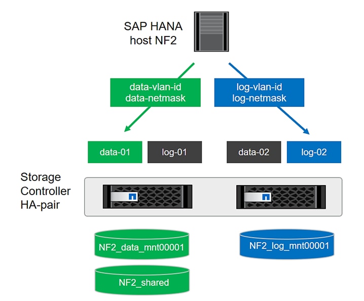
Procedure 1. Create Data Volume and Adjust Volume Options
Step 1. To create a data volume and adjust the volume options, run the following commands:
volume create -vserver hana-svm -volume NF2_data_mnt00001 -aggregate aggr1_1 -size 1536GB -state online -junction-path /NF2_data_mnt00001 -policy nfs-hana -snapshot-policy none -percent-snapshot-space 0 -space-guarantee none
vol modify -vserver hana-svm -volume NF2_data_mnt00001 -snapdir-access false
set advanced
vol modify -vserver hana-svm -volume NF2_data_mnt00001 -atime-update false
set admin
Procedure 2. Create a Log Volume and Adjust the Volume Options
Step 1. To create a log volume and adjust the volume options, run the following commands:
volume create -vserver hana-svm -volume NF2_log_mnt00001 -aggregate aggr1_2 -size 512GB -state online -junction-path /NF2_log_mnt00001 -policy nfs-hana -snapshot-policy none -percent-snapshot-space 0 -space-guarantee none
vol modify -vserver hana-svm -volume NF2_log_mnt00001 -snapdir-access false
set advanced
vol modify -vserver hana-svm -volume NF2_log_mnt00001 -atime-update false
set admin
Procedure 3. Create a HANA Shared Volume and adjust the Volume Options
Step 1. To create a HANA shared volume and qtrees, and adjust the volume options, run the following commands:
volume create -vserver hana-svm -volume NF2_shared -aggregate aggr2_1 -size 1536GB -state online -junction-path /NF2_shared -policy nfs-hana -snapshot-policy none -percent-snapshot-space 0 -space-guarantee none
vol modify -vserver hana-svm -volume NF2_shared -snapdir-access false
set advanced
vol modify -vserver hana-svm -volume NF2_shared -atime-update false
set admin
Procedure 4. Create Directories for HANA Shared Volume
Step 1. To create the required directories for the HANA shared volume mount the shared volume temporally and create the required directories
lnx-jumphost:/mnt # mount <storage-hostname>:/NF2_shared /mnt/tmp
lnx-jumphost:/mnt # cd /mnt/tmp
lnx-jumphost:/mnt/tmp # mkdir shared usr-sap
lnx-jumphost:/mnt # cd ..
lnx-jumphost:/mnt/tmp # umount /mnt/tmp
Procedure 5. Update the Load-Sharing Mirror Relation
Step 1. To update the load-sharing mirror relation, run the following command:
snapmirror update-ls-set -source-path hana-svm:hana_rootvol
Procedure 6. Create Mount Points
Step 1. To create the required mount-point directories, take one of the following actions:
mkdir -p /hana/data/NF2/mnt00001
mkdir -p /hana/log/NF2/mnt00001
mkdir -p /hana/shared
mkdir -p /usr/sap/NF2
chmod 777 -R /hana/log/NF2
chmod 777 -R /hana/data/NF2
chmod 777 -R /hana/shared
chmod 777 -R /usr/sap/NF2
Procedure 7. Verify Domain Information Synchronization
To be able to mount the volumes inside the HANA nodes, the v4-id-domain information of NFS enabled hana-svm providing the HANA persistence access should tally with domain information in /etc/idmapd.conf of the HANA nodes.
Step 1. Compare the value on NetApp and /etc/idmapd.conf file of the HANA node to verify they are synchronized.
AA07-A400::> nfs show -vserver AA07-HANA-SVM -fields v4-id-domain
vserver v4-id-domain
------------- ---------------------
AA07-HANA-SVM nfsv4domain.flexpod.com
[root@vhanar86 ~]# vi /etc/idmapd.conf
[General]
#Verbosity = 0
# The following should be set to the local NFSv4 domain name
# The default is the host's DNS domain name.
Domain = nfsv4domain.flexpod.com
Mount File Systems
The mount options are identical for all file systems that are mounted to the host:
● /hana/data/NF2/mnt00001
● /hana/log/NF2/mnt00001
● /hana/shared
● /usr/sap/NF2
Table 26 lists the required mount options.
This example uses NFSv4.1 to connect the storage. However, NFSv3 is supported for SAP HANA single host systems.
For NFSv3, NFS locking must be switched off to avoid NFS lock cleanup operations in case of a software or server failure.
With NetApp ONTAP 9, the NFS transfer size can be configured up to 1MB. Specifically, with connections to the storage system over 10GBE, you must set the transfer size to 1MB to achieve the expected throughput values.
| Common Parameter |
NFSv4.1 |
NFS Transfer Size with ONTAP 9 |
| rw, bg, hard, timeo=600, intr, noatime |
vers=4, minorversion=1, lock |
rsize=1048576, wsize=1048576 |
Procedure 1. Mount the File Systems during System Boot using the /etc/fstab Configuration File
Note: The following examples show a SAP HANA database with SID=NF2 using NFSv4.1 and a NFS transfer size of 1MB.
Step 1. Add the file systems to the /etc/fstab configuration file.
cat /etc/fstab
<node01-data_lif01-ip>:/NF2_data_mnt00001 /hana/data/NF2/mnt00001 nfs rw,bg,vers=4,minorversion=1,hard,timeo=600,rsize=1048576,wsize=1048576,intr,noatime,lock 0 0
<node02-log_lif02-ip>:/NF2_log_mnt00001 /hana/log/NF2/mnt00001 nfs rw,bg,vers=4,minorversion=1,hard,timeo=600,rsize=1048576,wsize=1048576,intr,noatime,lock 0 0
<node01-shared_lif01-ip>:/NF2_shared/usr-sap /usr/sap/NF2 nfs rw,bg,vers=4,minorversion=1,hard,timeo=600,rsize=1048576,wsize=1048576,intr,noatime,lock 0 0
<node02-shared_lif02-ip>:/NF2_shared/shared /hana/shared nfs rw,bg,vers=4,minorversion=1,hard,timeo=600,rsize=1048576,wsize=1048576,intr,noatime,lock 0 0
Step 2. Run mount –a to mount the file systems on the host.
Step 3. Ensure the mounts have the ownership root:root and 777 for permissions, as previously set.
[root@vhanar86 ~]# df -h
Filesystem Size Used Avail Use% Mounted on
devtmpfs 126G 0 126G 0% /dev
tmpfs 126G 0 126G 0% /dev/shm
tmpfs 126G 17M 126G 1% /run
tmpfs 126G 0 126G 0% /sys/fs/cgroup
/dev/mapper/rhel-root 45G 3.5G 41G 8% /
/dev/sda2 1014M 223M 792M 22% /boot
/dev/sda1 599M 5.8M 594M 1% /boot/efi
xx.xxx.6.1:/NF2_data_mnt00001 1.5T 3.0G 1.5T 1% /hana/data/NF2/mnt00001
xx.xxx.4.2:/NF2_log_mnt00001 512G 5.9G 502G 3% /hana/log/NF2/mnt00001
xx.xxx.7.1:/NF2_shared/usr-sap 1.5T 4G 1.5T 5% /usr/sap/NF2
xx.xxx.7.2:/NF2_shared/shared 1.5T 4G 1.5T 5% /hana/shared
tmpfs 26G 0 26G 0% /run/user/1000
tmpfs 26G 0 26G 0% /run/user/0
Note: It is very important to ensure the ownership of mount points and their recursive directories are set to root:root and permissions to 777 before processing with SAP HANA installation.
SAN Switch Configuration – Part 2 – Enable HANA Persistence Presentation to FC SAN Booting Bare-Metal Nodes
This chapter contains the following:
● Create hana-svm Specific Device Alias for HANA Persistence LUNs Presentation
● Create HANA-SVM Specific Zone and Zonesets for HANA Persistence LUNs Presentation
This chapter explains how to configure the Cisco MDS 9000s for use in a FlexPod environment. The configuration explained in this section is only needed when configuring fibre channel storage access to SAP HANA Persistence LUNs. This is for FC booted bare-metal nodes being prepared for SAP HANA installation which would be presented with LUNs for /hana/data. /hana/lo and /hana/shared, and any scale-up systems.
Note: For virtualized SAP HANA, database filesystems such as /hana/data, /hana/log and /hana/shared are NFS mounted directly inside the HANA VMs.
Note: If FC connectivity is not leveraged for SAP HANA specific storage partitions in the deployment, this section can be skipped.
Create hana-svm Specific Device Alias for HANA Persistence LUNs Presentation
To create the hana-svm specific zone that is used solely for presentation of HANA persistence LUNs to designated hosts, you need the information of the logical ports it is connected to and the LIFs information. The LIFs information can be obtained from the array command line:
AA07-A400::> network interface show -vserver AA07-HANA-SVM -data-protocol fcp
Logical Status Network Current Current Is
Vserver Interface Admin/Oper Address/Mask Node Port Home
----------- ---------- ---------- ------------------ ------------- ------- ----
AA07-HANA-SVM
fcp_hana_1a up/up 20:10:d0:39:ea:29:ce:d4
AA07-A400-01 5a true
fcp_hana_1b up/up 20:08:d0:39:ea:29:ce:d4
AA07-A400-01 5b true
fcp_hana_2a up/up 20:09:d0:39:ea:29:ce:d4
AA07-A400-02 5a true
fcp_hana_2b up/up 20:0e:d0:39:ea:29:ce:d4
AA07-A400-02 5b true
4 entries were displayed..
Procedure 1. Add Device Aliases for LIFs Specific to hana-svm for Fabric A - Cisco MDS 9132T A to create Zone
Step 1. From the global configuration mode, run the following commands:
device-alias mode enhanced
device-alias database
device-alias name HANA-SVM-fcp-lif-01a pwwn <lif-fcp_hana_1a-wwpn>
device-alias name HANA-SVM-fcp-lif-02a pwwn <lif-fcp_hana_2a-wwpn>
device-alias commit
Procedure 2. Add Device Aliases for LIFs Specific to hana-svm for Fabric B - Cisco MDS 9132T B to create Zone
Step 1. From the global configuration mode, run the following commands:
device-alias mode enhanced
device-alias database
device-alias name HANA-SVM-fcp-lif-01b pwwn <lif-fcp_hana_1b-wwpn>
device-alias name HANA-SVM-fcp-lif-02b pwwn <lif-fcp_hana_2b-wwpn>
device-alias commit
Create HANA-SVM Specific Zone and Zonesets for HANA Persistence LUNs Presentation
Note: Since Smart Zoning is enabled, a single zone is created with all host initiators and targets for the HANA_SVM instead of creating separate zones for each host. If a new host is added, its initiator can simply be added to appropriate zone in each MDS switch and the zoneset is reactivated.
Procedure 1. Cisco MDS 9132T A
Step 1. To create the required zones and zoneset on Fabric A, run the following commands:
configure terminal
zone name HANA-SVM-Fabric-A vsan <vsan-a-id>
member device-alias FC-Boot-bm-node1-A init
member device-alias FC-Boot-bm-node2-A init
member device-alias HANA-SVM-fcp-lif-01a target
member device-alias HANA-SVM-fcp-lif-02a target
exit
zoneset name FlexPod-Fabric-A vsan <vsan-a-id>
member HANA-SVM-Fabric-A
exit
zoneset activate name FlexPod-Fabric-A vsan <vsan-a-id>
show zoneset active
copy r s
Procedure 2. Cisco MDS 9148T B
Step 1. To create the required zone and zoneset on Fabric B, run the following commands:
configure terminal
zone name hana-svm-Fabric-B vsan <vsan-b-id>
member device-alias FC-Boot-bm-node1-B init
member device-alias FC-Boot-bm-node2-B init
member device-alias HANA-SVM-fcp-lif-01b target
member device-alias HANA-SVM-fcp-lif-02b target
exit
zoneset name Fabric-B vsan <vsan-b-id>
member hana-svm-Fabric-B
exit
zoneset activate name Fabric-B vsan <vsan-b-id>
exit
show zoneset active
copy r s
Bare-metal FC SAN Booting SAP HANA Node Preparation
This chapter contains the following:
● Access Cisco Intersight and Launch KVM with vMedia
This chapter details the preparation of bare-metal FC booting HANA nodes based on SLES for SAP Applications 15 SP4 and RHEL 8.6. It provides the Linux Operating System installation procedure using SAN Boot and includes operating system customization to fulfill all SAP HANA requirements.
Procedure 1. Download Linux ISOs
Step 1. Click the following link:
RHEL for SAP Solutions of x86_64 ver 8.6 ISO or SLES for SAP 15 SP4 ISO
Note: You will need a Red Hat Customer or SUSE account to download the DVD ISOs.
Step 2. Download the .iso file.
Access Cisco Intersight and Launch KVM with vMedia
The Cisco Intersight KVM enables the administrators to begin the installation of the operating system (OS) through remote media. It is necessary to log into the Cisco Intersight to access KVM.
Procedure 1. Log into Cisco Intersight and Access KVM
Step 1. Log into Cisco Intersight.
Step 2. From the main menu, select Infrastructure Service > Servers.
Step 3. Find the Server with the desired Server Profile assigned and click “…” for more options.
Step 4. Click Launch vKVM.
Note: Since the Linux ISO image will be mapped to the vKVM, it is important to use the standard vKVM and not the Tunneled vKVM and that the Cisco Intersight interface is being run from a subnet that has direct access to the subnet that the CIMC IPs (10.107.0.112 in this example) are provisioned on.
Step 5. Follow the prompts and ignore certificate workings (if any) and launch the HTML5 KVM console.
Step 6. Repeat steps 1 - 5 to launch the HTML5 KVM console for all the ESXi servers.
Procedure 1. Prepare the Server for the OS Installation
Note: Follow these steps on each ESXi host.
Step 1. In the KVM window, click Virtual Media > vKVM-Mapped vDVD.
Step 2. Browse and select the RHEL or SLES ISO image file downloaded in the last in Procedure 1 above.
Step 3. Click Map Drive.
Step 4. Select Power > Reset System and Confirm to reboot the Server if the server is showing shell prompt. If the server is shutdown, select Power > Power On System.
Step 5. Monitor the server boot process in the KVM. The server should find the boot LUNs and begin to load the OS installer.
Procedure 2. Operating System Installation
The Linux operating system installations follows the Red Hat or SUSE specific installation guides:
● Red Hat Enterprise Linux 8 - Configuring RHEL 8 for SAP HANA 2 installation
● SUSE Linux Enterprise Server for SAP Applications 15 SP4 Guide
Procedure 3. Operating System configuration
This step details how to manually define the file systems before the operating system configuration and SAP HANA installation.
Step 1. SSH into the virtual machine as root.
Step 2. Make to configure the recommended operating system settings according to the SAP notes and apply the latest security patches to the new system before installing SAP HANA.
● SAP Note 277299 - Red Hat Enterprise Linux 8.x: Installation and Configuration
● SAP Note 2777782 - SAP HANA DB: Recommended OS Settings for RHEL 8
● SAP Note 2578899 - SUSE Linux Enterprise Server 15: Installation Note
● SAP Note 2684254 - SAP HANA DB: Recommended OS Settings for SLES 15 / SLES for SAP Applications 15
SAP HANA Scale-Up System Provisioning on FC SAN Booting Bare-metal Nodes
This chapter contains the following:
● Configure SAP HANA Scale-up Systems
● Configuration Example for an SAP HANA Scale-up System
Table 25 lists the required variables used in this section.
| Variable |
Value |
| IP address LIF for SAP HANA shared (on storage node1) |
<node01-shared_lif01-ip> |
| IP address LIF for SAP HANA shared (on storage node2) |
<node02-shared_lif02-ip> |
Each SAP HANA host uses at least two FCP ports for the data and log LUNs of the SAP HANA system and has network interfaces connected to the storage network, which is used for the SAP HANA shared filesystem. In case of Scale-up system, the /hana/shared can also be a LUN formatted in xfs filesystem [like that of data and log mounts], as it is local to the system. The LUNs must be distributed to the storage nodes, as shown in Figure 13, so that a maximum of eight data and eight log volumes are stored on a single storage node.
The limitation of having six SAP HANA hosts per storage node is only valid for production SAP HANA systems for which the storage-performance key performance indicators defined by SAP must be fulfilled. For nonproduction SAP HANA systems, the maximum number is higher and must be determined during the sizing process.
Configure SAP HANA Scale-up Systems
Figure 13 shows the volume configuration of four scale-up SAP HANA systems. The data and log volumes of each SAP HANA system are distributed to different storage controllers. For example, volume SID1_data_mnt00001 is configured on controller A and volume SID1_log_mnt00001 is configured on controller B. Within each volume, a single LUN is configured.
Figure 13. Volume Layout for SAP HANA Scale-up Systems
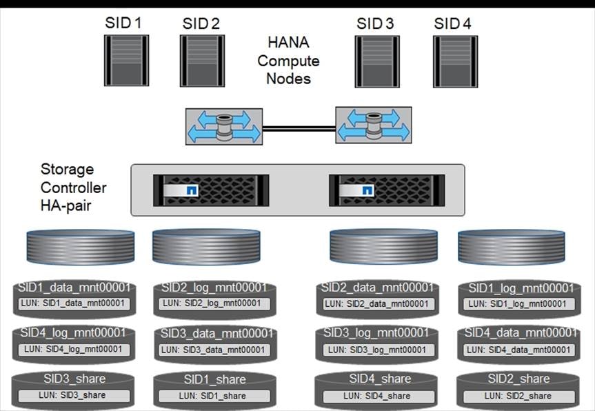
For each SAP HANA host, a data volume, a log volume, and a volume for /hana/shared are configured. Table 28 lists an example configuration with four SAP HANA scale-up systems.
Table 28. Volume Configuration for SAP HANA Scale-up Systems
| Purpose |
Aggregate 1 at Controller A |
Aggregate 2 at Controller A |
Aggregate 1 at Controller B |
Aggregate 2 at Controller B |
| Data, log, and shared volumes for system SID1 |
Data volume: SID1_data_mnt00001 |
Shared volume: SID1_shared |
– |
Log volume: SID1_log_mnt00001 |
| Data, log, and shared volumes for system SID2 |
– |
Log volume: SID2_log_mnt00001 |
Data volume: SID2_data_mnt00001 |
Shared volume: SID2_shared |
| Data, log, and shared volumes for system SID3 |
Shared volume: SID3_shared |
Data volume: SID3_data_mnt00001 |
Log volume: SID3_log_mnt00001 |
– |
| Data, log, and shared volumes for system SID4 |
Log volume: SID4_log_mnt00001 |
– |
Shared volume: SID4_shared |
Data volume: SID4_data_mnt00001 |
Table 29 lists an example mount point configuration for a scale-up system.
Table 29. Mount Points for Scale-up Systems
| LUN |
Mount Point at HANA Host |
Note |
| SID1_data_mnt00001 |
/hana/data/SID1/mnt00001 |
Mounted using /etc/fstab entry |
| SID1_log_mnt00001 |
/hana/log/SID1/mnt00001 |
Mounted using /etc/fstab entry |
| SID1_shared |
/hana/shared/SID1 |
Mounted using /etc/fstab entry |
Configuration Example for an SAP HANA Scale-up System
The following examples show an SAP HANA database with SID=FCS and a server RAM size of 1.5TB. For different server RAM sizes, the required volume sizes are different.
In this example, FC LUN formatted with xfs is used for /hana/shared, since it is a scale-up system and /hana/shared is local to the system.
For a detailed description of the capacity requirements for SAP HANA, see the SAP HANA Storage Requirements white paper.
Procedure 1. Create Volumes and Adjust Volume Options
Step 1. To create a data, log, and shared volume and adjust the volume options, run the following commands:
volume create -vserver AA07-HANA-SVM -volume FCS_data_mnt00001 -aggregate aggr1_1 -size 1750GB -state online -snapshot-policy none -percent-snapshot-space 0 -space-guarantee none
volume create -vserver AA07-HANA-SVM -volume FCS_log_mnt00001 -aggregate aggr1_2 -size 700GB -state online -snapshot-policy none -percent-snapshot-space 0 -space-guarantee none
volume create -vserver AA07-HANA-SVM -volume FCS_shared -aggregate aggr2_1 -size 1750GB -state online -snapshot-policy none -percent-snapshot-space 0 -space-guarantee none
vol modify -vserver hana-svm -volume FCS* -snapdir-access false
Step 1. To create a data, log and shared LUNS run the following commands:
lun create -vserver AA07-HANA-SVM -volume FCS_data_mnt00001 -lun FCS_data_mnt00001 -size 1.5TB -ostype Linux -space-reserve disabled
lun create -vserver AA07-HANA-SVM -volume FCS_log_mnt00001 -lun FCS_log_mnt00001 -size 512G -ostype Linux -space-reserve disabled
lun create -vserver AA07-HANA-SVM -volume FCS_shared -lun FCS_shared -size 1.5TB -ostype Linux -space-reserve disabled
Procedure 3. Map the LUNs to the hosts
Step 1. To create a map the LUNs to the host server-01, run the following commands:
lun map -vserver AA07-HANA-SVM -volume FCS_data_mnt00001 -lun FCS_data_mnt00001 -igroup aa07-FCP-bm-rhel
lun map -vserver AA07-HANA-SVM -volume FCS_log_mnt00001 -lun FCS_log_mnt00001 -igroup aa07-FCP-bm-rhel
lun map -vserver AA07-HANA-SVM -volume FCS_shared -lun FCS_shared -igroup aa07-FCP-bm-rhel
Procedure 4. Update the Load-Sharing Mirror Relation
Step 1. To update the load-sharing mirror relation, run the following command:
snapmirror update-ls-set -source-path AA07-HANA-SVM:hana_rootvol
Before setting up the host, NetApp SAN host utilities must be downloaded from the NetApp Support site and installed on the HANA servers. The host utility documentation includes information about additional software that must be installed depending on the FCP HBA used.
The documentation also contains information on multipath configurations that are specific to the Linux version used. This document explains the required configuration steps for SLES 12 SP1 or higher and RHEL 7.2 or later, as described in the Linux Host Utilities 7.1 Installation and Setup Guide.
Procedure 1. Configure Multipathing
Step 1. Run the Linux rescan-scsi-bus.sh -a command on each server to discover new LUNs.
Step 2. Run the sanlun lun show command and verify that all required LUNs are visible. The following example shows the sanlun lun show command output for scale-up HANA system with one data LUN, one LOG LUN, and a LUN for /hana/shared. The output shows the LUNs and the corresponding device files, such as LUN FCS_data_mnt00001 and the device file /dev/sdag Each LUN has four FC paths from the host to the storage controllers.
aa07-FCP-bm-rhel:~ # sanlun lun show
controller(7mode/E-Series)/ device host lun
vserver(cDOT/FlashRay) lun-pathname filename adapter protocol size product
--------------------------------------------------------------------------------------------------------------------------
AA07-HANA-SVM /vol/FCS_shared_FC/FCS_shared /dev/sdr host4 FCP 1.5t cDOT
AA07-HANA-SVM /vol/FCS_shared_FC/FCS_shared /dev/sdq host4 FCP 1.5t cDOT
AA07—HANA-SVM /vol/FCS_shared_FC/FCS_shared /dev/sdp host0 FCP 1.5t cDOT
AA07-HANA-SVM /vol/FCS_shared_FC/FCS_shared /dev/sdo host0 FCP 1.5t cDOT
AA07-Infra-SVM /vol/server_boot/aa07-FCP-bm-rhel-boot /dev/sdl host4 FCP 100g cDOT
AA07-HANA-SVM /vol/FCS_data_mnt00001/FCS_data_mnt00001 /dev/sdm host4 FCP 1.5t cDOT
AA07-HANA-SVM /vol/FCS_log_mnt00001/FCS_log_mnt00001 /dev/sdn host4 FCP 512g cDOT
AA07-HANA-SVM /vol/FCS_data_mnt00001/FCS_data_mnt00001 /dev/sdj host4 FCP 1.5t cDOT
AA07-HANA-SVM /vol/FCS_log_mnt00001/FCS_log_mnt00001 /dev/sdk host4 FCP 512g cDOT
AA07-Infra-SVM /vol/server_boot/aa07-FCP-bm-rhel-boot /dev/sdi host4 FCP 100g cDOT
AA07-HANA-SVM /vol/FCS_data_mnt00001/FCS_data_mnt00001 /dev/sdg host0 FCP 1.5t cDOT
AA07-HANA-SVM /vol/FCS_log_mnt00001/FCS_log_mnt00001 /dev/sde host0 FCP 512g cDOT
AA07-HANA-SVM /vol/FCS_log_mnt00001/FCS_log_mnt00001 /dev/sdh host0 FCP 512g cDOT
AA07-HANA-SVM /vol/FCS_data_mnt00001/FCS_data_mnt00001 /dev/sdd host0 FCP 1.5t cDOT
AA07-Infra-SVM /vol/server_boot/aa07-FCP-bm-rhel-boot /dev/sdf host0 FCP 100g cDOT
AA07-Infra-SVM /vol/server_boot/aa07-FCP-bm-rhel-boot /dev/sdc host0 FCP 100g cDOT
Step 3. Run the multipath -ll command to get the worldwide identifiers (WWIDs) for the device file names.
Note: In this example, there are four LUNs.
aa07-FCP-bm-rhel:~ # multipath -ll
3600a0980383146507a5d53765a496d71 dm-5 NETAPP,LUN C-Mode
size=100G features='3 queue_if_no_path pg_init_retries 50' hwhandler='1 alua' wp=rw
|-+- policy='service-time 0' prio=50 status=active
| |- 0:0:0:0 sdc 8:32 active ready running
| `- 4:0:0:0 sdi 8:128 active ready running
`-+- policy='service-time 0' prio=10 status=enabled
|- 0:0:1:0 sdf 8:80 active ready running
`- 4:0:1:0 sdl 8:176 active ready running
3600a0980383146507a5d53765a496e43 dm-16 NETAPP,LUN C-Mode
size=1.5T features='3 queue_if_no_path pg_init_retries 50' hwhandler='1 alua' wp=rw
|-+- policy='service-time 0' prio=50 status=active
| |- 0:0:0:3 sdo 8:224 active ready running
| `- 4:0:0:3 sdq 65:0 active ready running
`-+- policy='service-time 0' prio=10 status=enabled
|- 0:0:1:3 sdp 8:240 active ready running
`- 4:0:1:3 sdr 65:16 active ready running
3600a0980383146507a5d53765a496d73 dm-9 NETAPP,LUN C-Mode
size=1.5T features='3 queue_if_no_path pg_init_retries 50' hwhandler='1 alua' wp=rw
|-+- policy='service-time 0' prio=50 status=active
| |- 0:0:0:1 sdd 8:48 active ready running
| `- 4:0:0:1 sdj 8:144 active ready running
`-+- policy='service-time 0' prio=10 status=enabled
|- 0:0:1:1 sdg 8:96 active ready running
`- 4:0:1:1 sdm 8:192 active ready running
3600a0980383146514324523637544247 dm-6 NETAPP,LUN C-Mode
size=512G features='3 queue_if_no_path pg_init_retries 50' hwhandler='1 alua' wp=rw
|-+- policy='service-time 0' prio=50 status=active
| |- 0:0:1:2 sdh 8:112 active ready running
| `- 4:0:1:2 sdn 8:208 active ready running
`-+- policy='service-time 0' prio=10 status=enabled
|- 0:0:0:2 sde 8:64 active ready running
`- 4:0:0:2 sdk 8:160 active ready running
Step 4. Edit the /etc/multipath.conf file and add the WWIDs and alias names.
aa07-FCP-bm-rhel:~ # cat /etc/multipath.conf
multipath {
wwid 3600a0980383146507a5d53765a496d73
alias hana-svm-FCS_data_mnt00001
}
multipath {
wwid 3600a0980383146514324523637544247
alias hana-svm-FCS_log_mnt00001
}
multipath {
wwid 3600a0980383146507a5d53765a496e43
alias hana-svm-FCS_shared
}
}
Step 5. Run the multipath -r command to reload the device map.
Step 6. Verify the configuration by running the multipath -ll command to list all the LUNs, alias names, and active and standby paths.
Note: The multipath device dm-0 is the boot LUN from the infra-svm.
aa07-FCP-bm-rhel:~ # multipath -ll
3600a0980383146507a5d53765a496d71 dm-5 NETAPP,LUN C-Mode
size=100G features='3 queue_if_no_path pg_init_retries 50' hwhandler='1 alua' wp=rw
|-+- policy='service-time 0' prio=50 status=active
| |- 0:0:0:0 sdc 8:32 active ready running
| `- 4:0:0:0 sdi 8:128 active ready running
`-+- policy='service-time 0' prio=10 status=enabled
|- 0:0:1:0 sdf 8:80 active ready running
`- 4:0:1:0 sdl 8:176 active ready running
Micron_5300_MTFDDAV240TDS_MSA24220AWC dm-1 ATA,Micron_5300_MTFD
size=224G features='0' hwhandler='0' wp=rw
`-+- policy='service-time 0' prio=1 status=active
`- 1:0:0:0 sda 8:0 active ready running
Micron_5300_MTFDDAV240TDS_MSA24220AWD dm-0 ATA,Micron_5300_MTFD
size=224G features='0' hwhandler='0' wp=rw
`-+- policy='service-time 0' prio=1 status=active
`- 2:0:0:0 sdb 8:16 active ready running
hana-svm-FCS_data_mnt00001 (3600a0980383146507a5d53765a496d73) dm-9 NETAPP,LUN C-Mode
size=1.0T features='3 queue_if_no_path pg_init_retries 50' hwhandler='1 alua' wp=rw
|-+- policy='service-time 0' prio=50 status=active
| |- 0:0:0:1 sdd 8:48 active ready running
| `- 4:0:0:1 sdj 8:144 active ready running
`-+- policy='service-time 0' prio=10 status=enabled
|- 0:0:1:1 sdg 8:96 active ready running
`- 4:0:1:1 sdm 8:192 active ready running
hana-svm-FCS_log_mnt00001 (3600a0980383146514324523637544247) dm-6 NETAPP,LUN C-Mode
size=512G features='3 queue_if_no_path pg_init_retries 50' hwhandler='1 alua' wp=rw
|-+- policy='service-time 0' prio=50 status=active
| |- 0:0:1:2 sdh 8:112 active ready running
| `- 4:0:1:2 sdn 8:208 active ready running
`-+- policy='service-time 0' prio=10 status=enabled
|- 0:0:0:2 sde 8:64 active ready running
`- 4:0:0:2 sdk 8:160 active ready running
hana-svm-FCS_shared (3600a0980383146507a5d53765a496e43) dm-16 NETAPP,LUN C-Mode
size=1.5T features='3 queue_if_no_path pg_init_retries 50' hwhandler='1 alua' wp=rw
|-+- policy='service-time 0' prio=50 status=active
| |- 0:0:0:3 sdo 8:224 active ready running
| `- 4:0:0:3 sdq 65:0 active ready running
`-+- policy='service-time 0' prio=10 status=enabled
|- 0:0:1:3 sdp 8:240 active ready running
`- 4:0:1:3 sdr 65:16 active ready running
Procedure 2. Create File Systems
Step 1. To create the XFS file system on each LUN belonging to the HANA system, run the following commands:
aa07-FCP-bm-rhel:/ # mkfs.xfs -f /dev/mapper/hana-svm-FCS_data_mnt00001
aa07-FCP-bm-rhel:/ # mkfs.xfs -f /dev/mapper/hana-svm-FCS_log_mnt00001
aa07-FCP-bm-rhel:/ # mkfs.xfs -f /dev/mapper/hana-svm-FCS_shared
Procedure 3. Create Mount Points
Step 1. To create the required mount-point directories, run the following commands:
mkdir -p /hana/data/FCS/mnt00001
mkdir -p /hana/log/FCS/mnt00001
mkdir -p /hana/shared
mkdir -p /usr/sap/FCS
chmod 777 -R /hana/log/FCS
chmod 777 -R /hana/data/FCS
chmod 777 -R /hana/shared
chmod 777 -R /usr/sap/FCS
Procedure 4. Mount File Systems during System Boot using /etc/fstab Configuration File
Step 1. Add the required file systems to the /etc/fstab configuration file.
Note: The XFS file systems for the data and log LUNs must be mounted with the relatime and inode64 mount options.
server-01:/ # cat /etc/fstab
/dev/mapper/hana-svm-FCS_shared /hana/shared xfs defaults 0 0
/dev/mapper/hana-svm-FCS_log_mnt00001 /hana/log/FCS/mnt00001 xfs relatime,inode64 0 0
/dev/mapper/hana-svm-FCS_data_mnt00001 /hana/data/FCS/mnt00001 xfs relatime,inode64 0 0
Step 2. Run mount –a to mount the file systems on the host.
This chapter contains the following:
For information about the SAP HANA installation, please use the official SAP documentation, which describes the installation process with and without the SAP unified installer.
Note: Read the SAP Notes before you start the installation (see Important SAP Notes) These SAP Notes contain the latest information about the installation, as well as corrections to the installation documentation: SAP HANA Server Installation and Update Guide
Read the following SAP Notes before you start the installation. These SAP Notes contain the latest information about the installation, as well as corrections to the installation documentation.
The latest SAP Notes can be found here: https://service.sap.com/notes.
SAP HANA Server installation and update guide: https://help.sap.com/docs/SAP_HANA_PLATFORM/2c1988d620e04368aa4103bf26f17727/7eb0167eb35e4e2885415205b8383584.html
SAP HANA network requirements white paper: https://www.sap.com/documents/2016/08/1cd2c2fb-807c-0010-82c7-eda71af511fa.html
SAP HANA Hardware and Cloud Measurement Tools: https://help.sap.com/docs/HANA_HW_CLOUD_TOOLS/02bb1e64c2ae4de7a11369f4e70a6394/7e878f6e16394f2990f126e639386333.html
SAP HANA: Supported Operating Systems: https://launchpad.support.sap.com/#/notes/2235581
SAP HANA on VMware vSphere Best Practices and Reference Architecture Guide: https://core.vmware.com/resource/sap-hana-vmware-vsphere-best-practices-and-reference-architecture-guide
SAP HANA on VMware vSphere: https://wiki.scn.sap.com/wiki/display/VIRTUALIZATION/SAP+HANA+on+VMware+vSphere
Recover the Secure ESXi configuration: https://docs.vmware.com/en/VMware-vSphere/7.0/com.vmware.vsphere.security.doc/GUID-23FFB8BB-BD8B-46F1-BB59-D716418E889A.html
VMware Cisco custom image for ESXi 7.0 U3: https://customerconnect.vmware.com/downloads/details?downloadGroup=OEM-ESXI70U3-CISCO&productId=974
VMware vCenter Server 7.0U3: https://customerconnect.vmware.com/downloads/details?downloadGroup=VC70U3H&productId=974&rPId=95488
SAP HANA on VMware vSphere 7.0 in production: https://launchpad.support.sap.com/#/notes/2937606
Red Hat
Red Hat Enterprise Linux 8 - Configuring RHEL 8 for SAP HANA 2 installation: https://access.redhat.com/documentation/de-de/red_hat_enterprise_linux/8/html/configuring_rhel_8_for_sap_hana_2_installation/index
Red Hat Enterprise Linux 8.x: Installation and Configuration: https://launchpad.support.sap.com/#/notes/2772999
SAP HANA DB: Recommended OS Settings for RHEL 8: https://launchpad.support.sap.com/#/notes/2777782
SUSE
SUSE Linux Enterprise Server for SAP Applications 15 SP4 Guide: https://documentation.suse.com/sles-sap/15-SP4/html/SLES-SAP-guide/index.html
SUSE Linux Enterprise Server 15 Installation Note: https://launchpad.support.sap.com/#/notes/2578899
SAP HANA DB: Recommended OS Settings for SLES 15 / SLES for SAP Applications 15: https://launchpad.support.sap.com/#/notes/2684254
NetApp Technical Reports
TR-4436-SAP HANA on NetApp AFF Systems with FCP
TR-4435: SAP HANA on NetApp AFF Systems with NFS
TR-4614-SAP HANA Backup and Recovery with SnapCenter
TR-4646-SAP HANA Disaster Recovery with Storage Replication
FlexPod Management Tools Setup
This chapter contains the following:
● Cisco Intersight Hardware Compatibility List (HCL) Status
● NetApp ONTAP Tools 9.12 Deployment
● Provision Datastores using NetApp ONTAP Tools (Optional)
● Active IQ Unified Manager 9.12 Installation
● Configure Active IQ Unified Manager
● Deploy Cisco Intersight Assist Appliance
● Claim VMware vCenter using Cisco Intersight Assist Appliance
● Claim NetApp Active IQ Manager using Cisco Intersight Assist Appliance
● Claim Cisco Nexus Switches using Cisco Intersight Assist Appliance
● Claim Cisco MDS Switches using Cisco Intersight Assist Appliance
Cisco Intersight Hardware Compatibility List (HCL) Status
Cisco Intersight evaluates the compatibility of customer’s UCS system to check if the hardware and software have been tested and validated by Cisco or Cisco partners. Intersight reports validation issues after checking the compatibility of the server model, processor, firmware, adapters, operating system, and drivers, and displays the compliance status with the Hardware Compatibility List (HCL).
To determine HCL compatibility for VMware ESXi, Cisco Intersight uses Cisco UCS Tools. The Cisco UCS Tools is part of VMware ESXi Cisco custom ISO, and no additional configuration is required.
For more details on Cisco UCS Tools manual deployment and troubleshooting, refer to: https://intersight.com/help/saas/resources/cisco_ucs_tools#about_cisco_ucs_tools
Procedure 1. View Compute Node Hardware Compatibility
Step 1. To find detailed information about the hardware compatibility of a compute node, in Cisco Intersight select Infrastructure Service > Operate > Servers, click a server, select HCL.
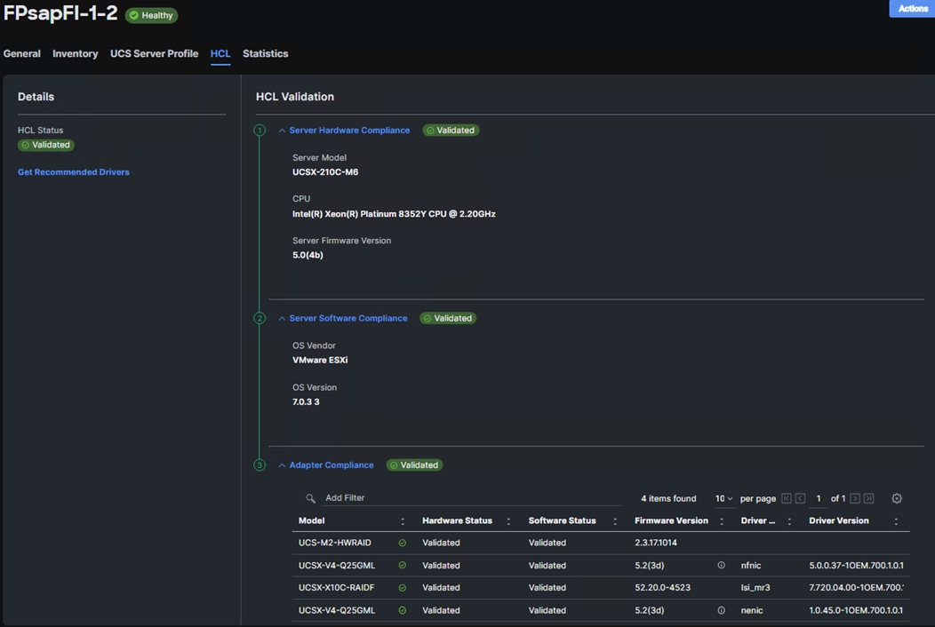
NetApp ONTAP Tools 9.12 Deployment
The NetApp ONTAP tools for VMware vSphere provide end-to-end life cycle management for virtual machines in VMware environments that use NetApp storage systems. It simplifies storage and data management for VMware environments by enabling administrators to directly manage storage within the vCenter Server. This topic describes the deployment procedures for the NetApp ONTAP Tools for VMware vSphere.
NetApp ONTAP Tools for VMware vSphere 9.12 Pre-installation Considerations
The following licenses are required for NetApp ONTAP Tools on storage systems that run NetApp ONTAP 9.8 or above:
● Protocol licenses (NFS, FCP, and/or iSCSI).
● NetApp FlexClone ((optional) Required for performing test failover operations for SRA and for vVols operations of VASA Provider.
● NetApp SnapRestore (for backup and recovery).
● The NetApp SnapManager Suite.
● NetApp SnapMirror or NetApp SnapVault (optional, required for performing failover operations for SRA and VASA Provider when using vVols replication).
The Backup and Recovery capability has been integrated with SnapCenter and requires additional licenses for SnapCenter to perform backup and recovery of virtual machines and applications.
Note: Beginning with NetApp ONTAP 9.10.1, all licenses are delivered as NLFs (NetApp License File). NLF licenses can enable one or more NetApp ONTAP features, depending on your purchase. NetApp ONTAP 9.10.1 also supports 28-character license keys using System Manager or the CLI. However, if an NLF license is installed for a feature, you cannot install a 28-character license key over the NLF license for the same feature.
Table 30. Port Requirements for NetApp ONTAP Tools
| TCP Port |
Requirement |
| 443 (HTTPS) |
Secure communications between VMware vCenter Server and the storage systems |
| 8143 (HTTPS) |
NetApp ONTAP Tools listens for secure communications |
| 9083 (HTTPS) |
VASA Provider uses this port to communicate with the vCenter Server and obtain TCP/IP settings |
Note: The requirements for deploying NetApp ONTAP Tools are listed here.
Procedure 1. Install NetApp ONTAP Tools Manually
Step 1. Download the NetApp ONTAP Tools 9.12 OVA (NETAPP-ONTAP-TOOLS-FOR-VMWARE-VSPHERE-9.11-8450.OVA) from NetApp support: ONTAP tools for VMware vSphere 9.12
Step 2. Launch the vSphere Web Client and navigate to Hosts and Clusters.
Step 3. Select ACTIONS for the FlexPod-DC datacenter and select Deploy OVF Template.
Step 4. Browse to the NetApp ONTAP tools OVA file and select the file.
Step 5. Enter the VM name and select a datacenter or folder to deploy the VM and click NEXT.
Step 6. Select a host cluster resource to deploy OVA and click NEXT.
Step 7. Review the details and accept the license agreement.
Step 8. Select the infra_datastore_1 volume and select the Thin Provision option for the virtual disk format.
Step 9. From Select Networks, select a destination network (for example, IB-MGMT) and click NEXT.
Step 10. From Customize Template, enter the NetApp ONTAP tools administrator password, vCenter name or IP address and other configuration details and click NEXT.
Step 11. Review the configuration details entered and click FINISH to complete the deployment of NetApp ONTAP-Tools VM.
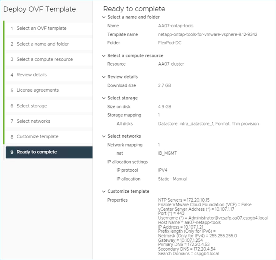
Step 12. Power on the NetApp ONTAP-tools VM and open the VM console.
Step 13. During the NetApp ONTAP-tools VM boot process, you see a prompt to install VMware Tools. From vCenter, right-click the ONTAP-tools VM > Guest OS > Install VMware Tools.
Note: Networking configuration and vCenter registration information was provided during the OVF template customization, therefore after the VM is up and running, NetApp ONTAP-Tools and vSphere API for Storage Awareness (VASA) is registered with vCenter.
Step 14. Refresh the vCenter Home Screen and confirm that the NetApp ONTAP tools is installed.
Note: The NetApp ONTAP tools vCenter plug-in is only available in the vSphere HTML5 Client and is not available in the vSphere Web Client.
Procedure 2. Download the NetApp NFS Plug-in for VAAI
Note: The NFS Plug-in for VAAI was previously installed on the ESXi hosts along with the Cisco UCS VIC drivers; it is not necessary to re-install the plug-in at this time. However, for any future additional ESXi host setup, instead of using esxcli commands, NetApp ONTAP-Tools can be utilized to install the NetApp NFS plug-in. The steps below upload the latest version of the plugin to NetApp ONTAP tools.
Step 1. Download the NetApp NFS Plug-in 2.0.1 for VMware file from: NetApp NFS Plug-in for VMware VAAI 2.0.1.
Step 2. Unzip the file and extract NetApp_bootbank_NetAppNasPlugin_2.0-16.vib from vib20 > NetAppNasPlugin.
Step 3. Rename the .vib file to NetAppNasPlugin.vib to match the predefined name that NetApp ONTAP tools uses.
Step 4. Click Settings in the NetApp ONTAP tool Getting Started page.
Step 5. Click NFS VAAI Tools tab.
Step 6. Click Change in the Existing version section.
Step 7. Browse and select the renamed .vib file and then click Upload to upload the file to the virtual appliance.
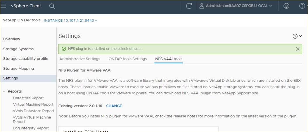
Note: The next step is only required on the hosts where NetApp VAAI plug-in was not installed alongside Cisco VIC driver installation.
Step 8. In the Install on ESXi Hosts section, select the ESXi host where the NFS Plug-in for VAAI is to be installed, and then click Install.
Step 9. Reboot the ESXi host after the installation finishes.
Procedure 3. Verify the VASA Provider
Note: The VASA provider for NetApp ONTAP is enabled by default during the installation of the NetApp ONTAP tools.
Step 1. From the vSphere Client, click Menu > ONTAP tools.
Step 2. Click Settings.
Step 3. Click Manage Capabilities in the Administrative Settings tab.
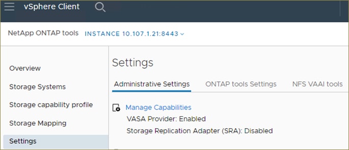
Step 4. In the Manage Capabilities dialog box, click Enable VASA Provider if it was not pre-enabled.
Step 5. Enter the IP address of the virtual appliance for NetApp ONTAP tools, VASA Provider, and VMware Storage Replication Adapter (SRA) and the administrator password, and then click Apply.
Procedure 4. Discover and Add Storage Resources
Step 1. Using the vSphere Web Client, log in to the vCenter. If the vSphere Web Client was previously opened, close the tab, and then reopen it.
Step 2. In the Home screen, click the Home tab and click ONTAP tools.
Note: When using the cluster admin account, add storage from the cluster level.
Note: You can modify the storage credentials with the vsadmin account or another SVM level account with role-based access control (RBAC) privileges. Refer to the NetApp ONTAP 9 Administrator Authentication and RBAC Power Guide for additional information.
Step 3. Click Storage Systems, and then click ADD under Add Storage System.
Step 4. Specify the vCenter Server where the storage will be located.
Step 5. In the Name or IP Address field, enter the storage cluster management IP.
Step 6. Enter admin for the username and the admin password for the cluster.
Step 7. Confirm Port 443 to Connect to this storage system.
Step 8. Click ADD to add the storage configuration to NetApp ONTAP tools.
Step 9. Wait for the Storage Systems to update. You might need to click Refresh to complete this update.
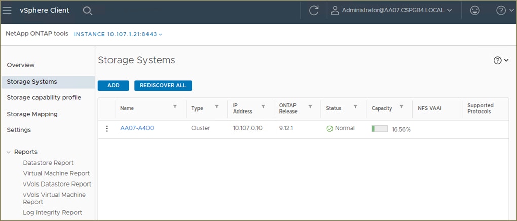
Step 10. From the vSphere Client Home page, click Hosts and Clusters.
Step 11. Right-click the FlexPod-DC datacenter, click NetApp ONTAP tools > Update Host and Storage Data.
Step 12. On the Confirmation dialog box, click OK. It might take a few minutes to update the data.
Procedure 5. Optimal Storage Settings for ESXi Hosts
Note: NetApp ONTAP tools enables the automated configuration of storage-related settings for all ESXi hosts that are connected to NetApp storage controllers.
Step 1. From the VMware vSphere Web Client Home page, click vCenter > Hosts and Clusters.
Step 2. Select a host and then click Actions > NetApp ONTAP tools > Set Recommended Values.
Step 3. In the NetApp Recommended Settings dialog box, select all the applicable values for the ESXi host.
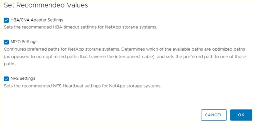
Note: This functionality sets values for HBAs and converged network adapters (CNAs), sets appropriate paths and path-selection plug-ins, and verifies appropriate settings for NFS I/O. A vSphere host reboot may be required after applying the settings.
Step 4. Click OK.
Provision Datastores using NetApp ONTAP Tools (Optional)
Using NetApp ONTAP tools, the administrator can provision an NFS, FC or iSCSI datastore and attach it to a single or multiple hosts in the cluster. The following steps describe provisioning a datastore and attaching it to the cluster.
Note: It is a NetApp best practice to use NetApp ONTAP tools to provision any additional datastores for the FlexPod infrastructure. When using VSC to create vSphere datastores, all NetApp storage best practices are implemented during volume creation and no additional configuration is needed to optimize performance of the datastore volumes.
Storage Capabilities
A storage capability is a set of storage system attributes that identifies a specific level of storage performance (storage service level), storage efficiency, and other capabilities such as encryption for the storage object that is associated with the storage capability.
Create the Storage Capability Profile
In order to leverage the automation features of VASA two primary components must first be configured. The Storage Capability Profile (SCP) and the VM Storage Policy. The Storage Capability Profile expresses a specific set of storage characteristics into one or more profiles used to provision a Virtual Machine. The SCP is specified as part of VM Storage Policy. NetApp ONTAP tools comes with several pre-configured SCPs such as Platinum, Bronze, and so on.
Note: The NetApp ONTAP tools for VMware vSphere plug-in also allows you to set Quality of Service (QoS) rule using a combination of maximum and/or minimum IOPs.
Procedure 1. Review or Edit the Built-In Profiles Pre-Configured with NetApp ONTAP Tools
Step 1. From the vCenter console, click Menu > ONTAP tools.
Step 2. In the NetApp ONTAP tools click Storage Capability Profiles.
Step 3. Select the Platinum Storage Capability Profile and select Clone from the toolbar.
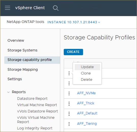
Step 4. Enter a name for the cloned SCP (for example, AFF_Platinum_Encrypted) and add a description if desired. Click NEXT.
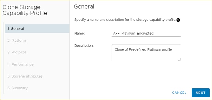
Step 5. Select All Flash FAS(AFF) for the storage platform and click NEXT. Go with default Any for Protocol.
Step 6. Select None to allow unlimited performance or set the desired minimum and maximum IOPS for the QoS policy group. Click NEXT.
Step 7. On the Storage attributes page, change the Encryption and Tiering policy to the desired settings and click NEXT. In the example below, Encryption was enabled.
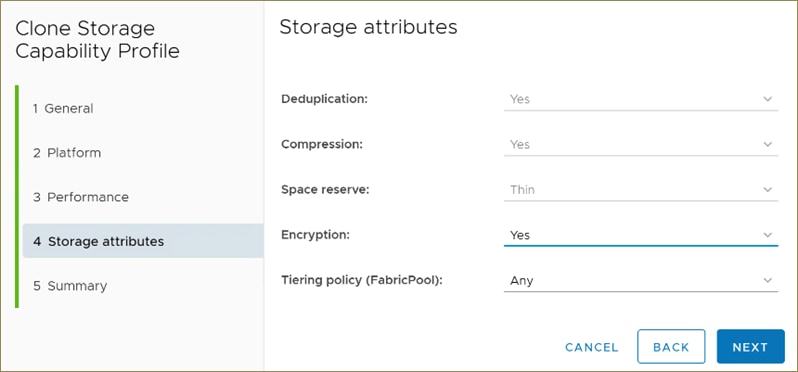
Step 8. Review the summary page and click FINISH to create the storage capability profile.
Note: It is recommended to Clone the Storage Capability Profile if you wish to make any changes to the predefined profiles rather than editing the built-in profile.
Procedure 2. Create a VM Storage Policy
Note: You must create a VM storage policy and associate SCP to the datastore that meets the requirements defined in the SCP.
Step 1. From the vCenter console, click Menu > Policies and Profiles.
Step 2. Select VM Storage Policies and click CREATE.
Step 3. Create a name for the VM storage policy and enter a description and click NEXT.
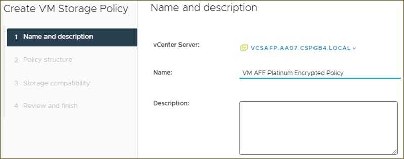
Step 4. Select Enable rules for NetApp.clustered.Data.ONTAP.VP.VASA10 storage located under the Datastore specific rules section and click NEXT.
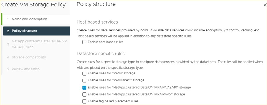
Step 5. On the Placement tab select the SCP created in the previous step and click NEXT.
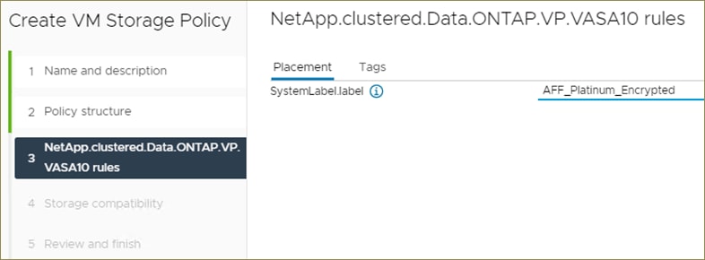
Step 6. All the datastores with matching capabilities are displayed, click NEXT.
Step 7. Review the policy summary and click FINISH.
Procedure 3. Provision NFS Datastore
Step 1. From the vCenter console, click Menu > ONTAP tools.
Step 2. From the NetApp ONTAP tools Home page, click Overview.
Step 3. In the Getting Started tab, click Provision.
Step 4. Click Browse to select the destination to provision the datastore.
Step 5. Select the type as NFS and Enter the datastore name (for example, NFS_DS_1).
Step 6. Provide the size of the datastore and the NFS Protocol.
Step 7. Check the storage capability profile and click NEXT.
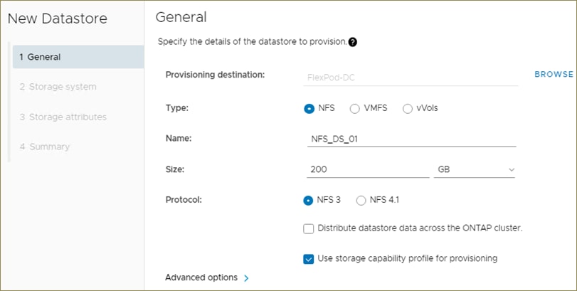
Step 8. Select the desired Storage Capability Profile, cluster name and the desired SVM to create the datastore. In this example, the Infra-SVM is selected.
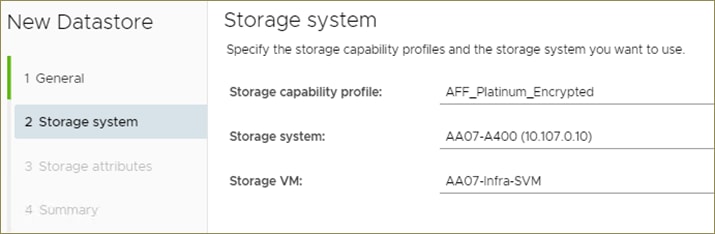
Step 9. Click NEXT.
Step 10. Select the aggregate name and click NEXT.
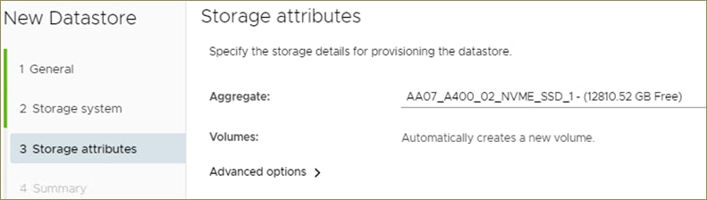
Step 11. Review the Summary and click FINISH.
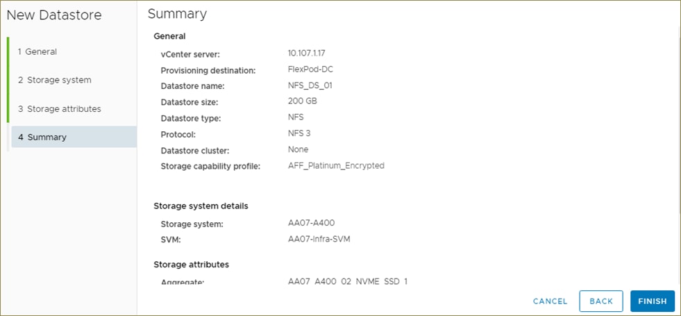
Step 12. The datastore is created and mounted on the hosts in the cluster. Click Refresh from the vSphere Web Client to see the newly created datastore.
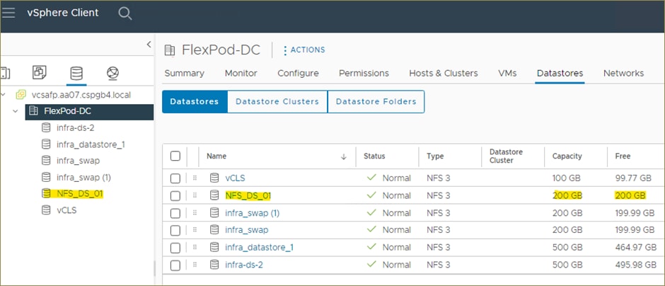
Step 13. Distributed datastore is supported from NetApp ONTAP 9.8, which provides FlexGroup volume on NetApp ONTAP storage. To create a Distributed Datastore across the NetApp ONTAP Cluster select NFS 4.1 and check the box for Distributed Datastore data across the NetApp ONTAP Cluster.
Active IQ Unified Manager 9.12 Installation
Active IQ Unified Manager enables customers to monitor and manage the health and performance of ONTAP storage systems and virtual infrastructure from a single interface. Unified Manager provides a graphical interface that displays the capacity, availability, protection, and performance status of the monitored storage systems. Active IQ Unified Manager is required to integrate NetApp storage with Cisco Intersight.
This section describes the steps to deploy NetApp Active IQ Unified Manager 9.12 as a virtual appliance.
Procedure 1. Install NetApp Active IQ Unified Manager 9.12
Step 1. Download NetApp Active IQ Unified Manager for VMware vSphere OVA file from: https://mysupport.netapp.com/site/products/all/details/activeiq-unified-manager/downloads-tab.
Step 2. In the VMware vCenter GUI, click VMs and Templates and then click Actions > Deploy OVF Template.
Step 3. Specify the location of the OVF Template and click NEXT.
Step 4. On the Select a name and folder page, enter a unique name for the VM, and select a deployment location, and then click NEXT.
Step 5. On the Select a compute resource screen, select the cluster where VM will be deployed and click NEXT.
Step 6. On the Review details page, verify the OVA template details and click NEXT.
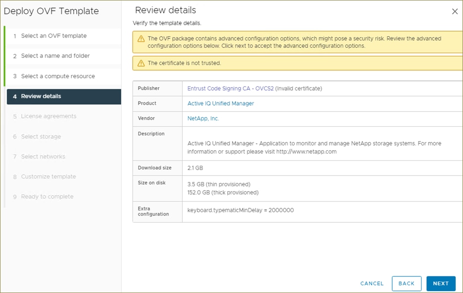
Step 7. On the License agreements page, read and check the box for I accept all license agreements. Click NEXT.
Step 8. On the Select storage page, select following parameters for the VM deployment:
a. Select the disk format for the VMDKs (for example, Think Provisioning).
b. Select a VM Storage Policy (for example, Datastore Default).
c. Select a datastore to store the deployed OVA template (for example, infra_datastore_1).
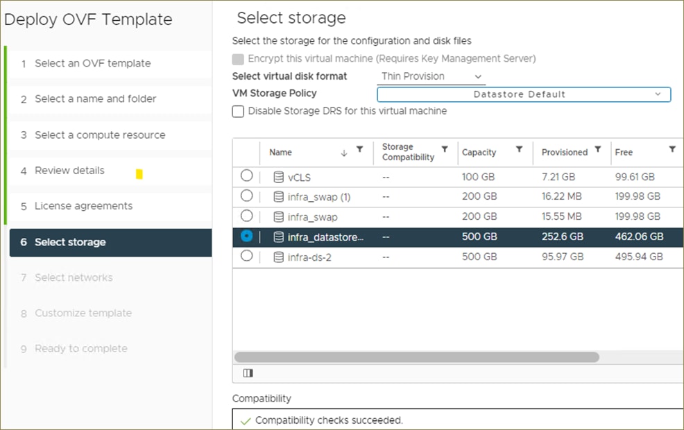
Step 9. Click NEXT.
Step 10. On the Select networks page, select the destination network (for example, IB-MGMT) and click NEXT.
Step 11. On the Customize template page, provide network details such as hostname, IP address, gateway, and DNS.
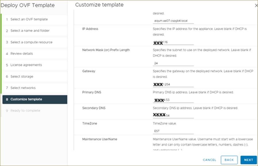
Note: Scroll through the customization template to ensure all required values are entered.
Step 12. Click NEXT.
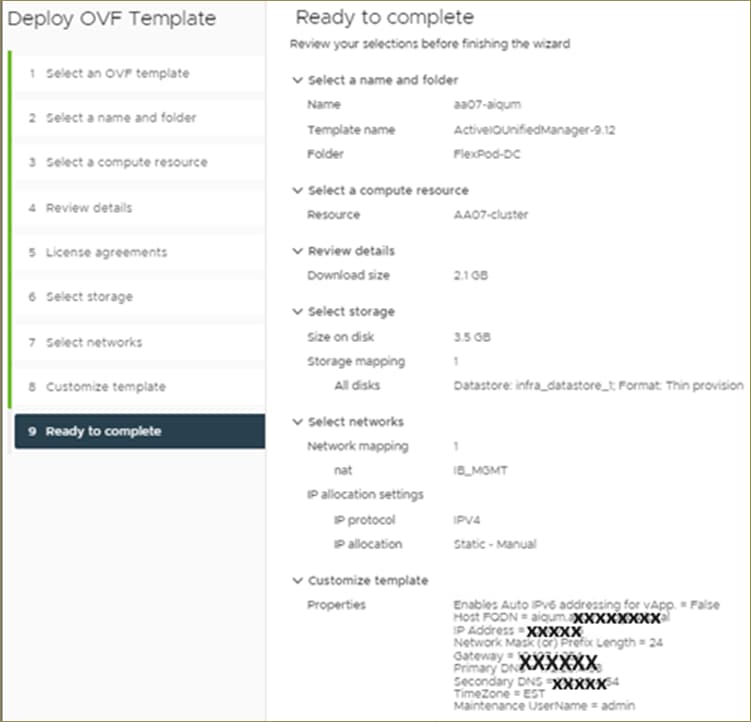
Step 13. On the Ready to complete page, review the settings and click FINISH. Wait for the VM deployment to complete before proceeding to the next step.
Step 14. Select the newly created Active IQ Unified Manager VM, right-click and select Power > Power On.
Step 15. While the virtual machine is powering on, click the prompt in the yellow banner to Install VMware tools.
Note: Because of timing, VMware tools might not install correctly. In that case VMware tools can be manually installed after Active IQ Unified Manager VM is up and running.
Step 16. Open the VM console for the Active IQ Unified Manager VM and login using the admin user.admin.
Step 17. Log into NetApp Active IQ Unified Manager using the IP address or URL displayed on the deployment screen using the maintenance user credentials created in the last step.
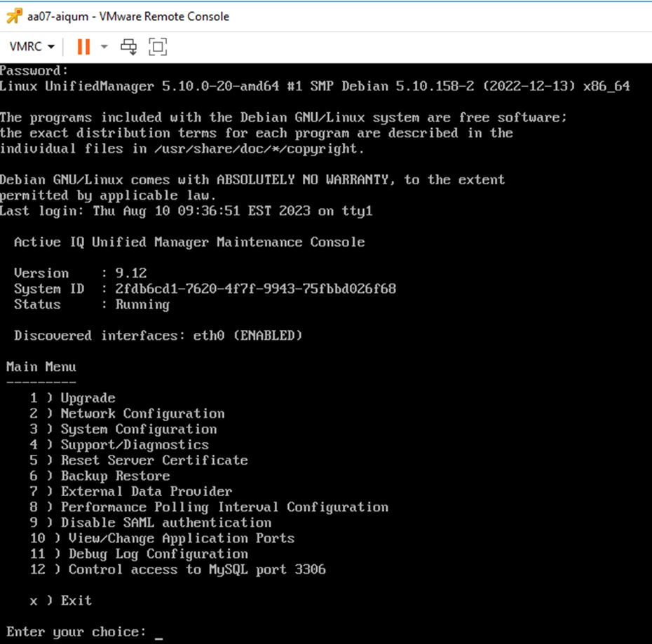
Configure Active IQ Unified Manager
Procedure 1. Initial Setup Active IQ Unified Manager and add Storage System
Step 1. Launch a web browser and log into Active IQ Unified Manger using the URL shown in the VM console.
Step 2. Enter the email address that Unified Manager will use to send alerts and the mail server configuration. Click Continue.
Step 3. Select Agree and Continue on the Set up AutoSupport configuration.
Step 4. Check the box for Enable API Gateway and click Continue.
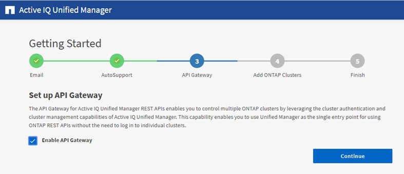
Step 5. Enter the ONTAP cluster hostname or IP address and the admin login credentials.
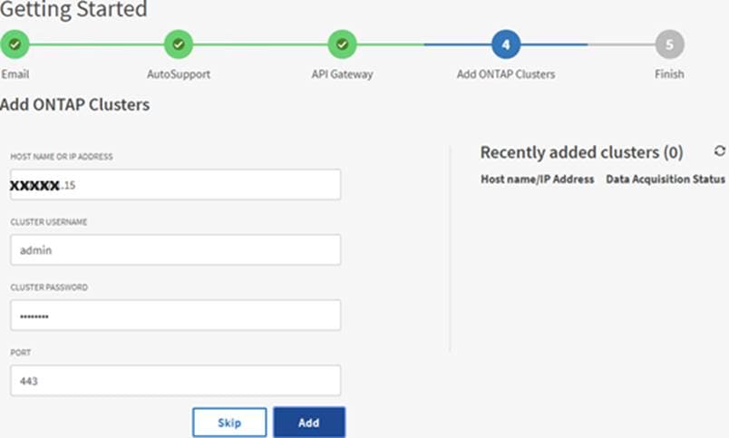
Step 6. Click Add.
Step 7. Click Yes to trust the self-signed cluster certificate and finish adding the storage system.
Note: The initial discovery process can take up to 15 minutes to complete.
Review Security Compliance with Active IQ Unified Manager
Active IQ Unified Manager identifies issues and makes recommendations to improve the security posture of ONTAP. Active IQ Unified Manager evaluates ONTAP storage based on recommendations made in the Security Hardening Guide for ONTAP 9. Items are identified according to their level of compliance with the recommendations. Review the Security Hardening Guide for NetApp ONTAP 9 (TR-4569) for additional information and recommendations for securing ONTAP 9.
Note: All events identified do not inherently apply to all environments, for example, FIPS compliance.
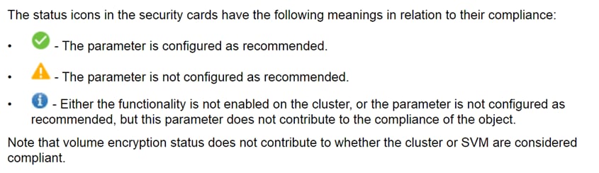
Procedure 1. Identify Security Events in Active IQ Unified Manager
Step 1. Navigate to the URL of the Active IQ Unified Manager and login.
Step 2. Select the Dashboard in Active IQ Unified Manager.
Step 3. Locate the Security card and note the compliance level of the cluster and SVM.
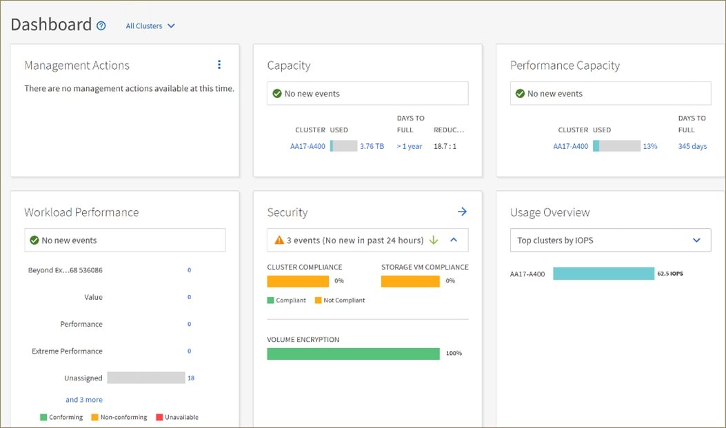
Deploy Cisco Intersight Assist Appliance
Cisco Intersight works with NetApp’s ONTAP storage and VMware vCenter using third-party device connectors and Cisco Nexus and MDS switches using Cisco device connectors. Since third-party infrastructure and Cisco switches do not contain any usable built-in Intersight device connector, Cisco Intersight Assist virtual appliance enables Cisco Intersight to communicate with these devices.
Note: A single Cisco Intersight Assist virtual appliance can support both NetApp ONTAP storage, VMware vCenter, and Cisco Nexus and MDS switches.
Figure 14. Managing NetApp and VMware vCenter through Cisco Intersight using Intersight Assist
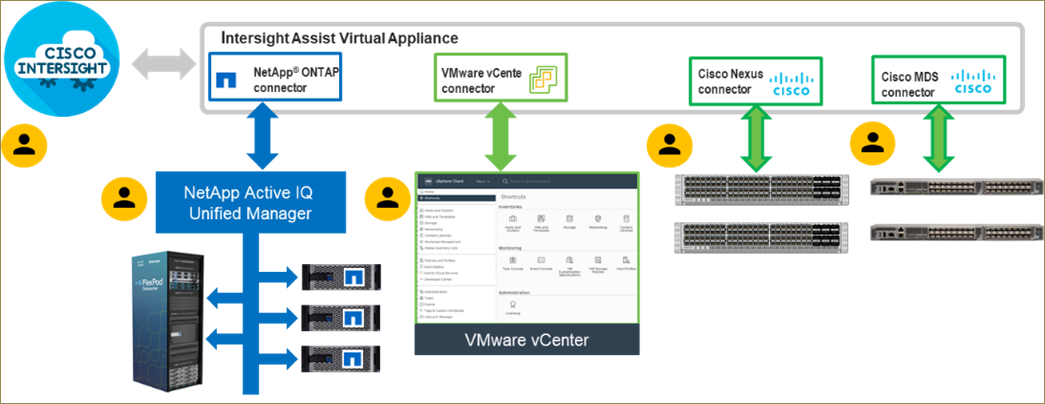
Procedure 1. Install Cisco Intersight Assist
Step 1. To install Cisco Intersight Assist from an Open Virtual Appliance (OVA), download the latest release of the Cisco Intersight Virtual Appliance for vSphere from https://software.cisco.com/download/home/286319499/type/286323047/release/1.0.9-499.
Note: It is important to install release 1.0.9-499 at a minimum.
Procedure 2. Set up DNS entries
Step 1. Setting up Cisco Intersight Virtual Appliance requires an IP address and 2 hostnames for that IP address. The hostnames must be in the following formats:
● myhost.mydomain.com: A hostname in this format is used to access the GUI. This must be defined as an A record and PTR record in DNS. The PTR record is required for reverse lookup of the IP address. If an IP address resolves to multiple hostnames, the first one in the list is used.
● dc-myhost.mydomain.com: The dc- must be prepended to your hostname. This hostname must be defined as the CNAME of myhost.mydomain.com. Hostnames in this format are used internally by the appliance to manage device connections.
Step 2. In this lab deployment the following information was used to deploy a Cisco Intersight Assist VM:
● Hostname: iafp.aa07.xxxxxx.local
● IP address: xx.xxx.1.18
● DNS Entries (Windows AD/DNS):
◦ A Record
![]()
◦ CNAME:
![]()
◦ PTR (reverse lookup):
![]()
For more information, refer to: https://www.cisco.com/c/en/us/td/docs/unified_computing/Intersight/b_Cisco_Intersight_Appliance_Getting_Started_Guide/b_Cisco_Intersight_Appliance_Install_and_Upgrade_Guide_chapter_00.html.
Procedure 3. Deploy Cisco Intersight OVA
Note: Ensure that the appropriate entries of type A, CNAME, and PTR records exist in the DNS, as explained in the previous section. Log into the vSphere Client and select Hosts and Clusters.
Step 1. From Hosts and Clusters, right-click the cluster and click Deploy OVF Template.
Step 2. Select Local file and click UPLOAD FILES. Browse to and select the intersight-appliance-installer-vsphere-1.0.9-342.ova or the latest release file and click Open. Click NEXT.
Step 3. Name the Intersight Assist VM and select the location. Click NEXT.
Step 4. Select the cluster and click NEXT.
Step 5. Review details, click Ignore All, and click NEXT.
Step 6. Select a deployment configuration. If only the Intersight Assist functionality is needed, a deployment size of Tiny can be used. If Intersight Workload Optimizer (IWO) is being used in this Intersight account, use the Small deployment size. Click NEXT.
Step 7. Select the appropriate datastore (for example, infra_datastore_1) for storage and select the Thin Provision virtual disk format. Click NEXT.
Step 8. Select appropriate management network (for example, IB-MGMT Network) for the OVA. Click NEXT.
Note: The Cisco Intersight Assist VM must be able to access both the IB-MGMT network on FlexPod and Intersight.com. Select and configure the management network appropriately. If selecting IB-MGMT network on FlexPod, make sure the routing and firewall is setup correctly to access the Internet.
Step 9. Fill in all values to customize the template. Click NEXT.
Step 10. Review the deployment information and click FINISH to deploy the appliance.
Step 11. When the OVA deployment is complete, right-click the Intersight Assist VM and click Edit Settings.
Step 12. Expand CPU and verify the socket configuration. For example, in the following deployment, on a 2-socket system, the VM was configured for 16 sockets:
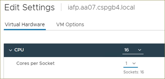
Step 13. Adjust the Cores per Socket so that the number of Sockets matches the server CPU configuration (2 sockets in this deployment):
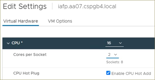
Step 14. Click OK.
Step 15. Right-click the Intersight Assist VM and select Power > Power On.
Step 16. When the VM powers on and login prompt is visible (use remote console), connect to https://<intersight-assist-fqdn>.
Note: It may take a few minutes for https://<intersight-assist-fqdn> to respond.
Step 17. Navigate the security prompts and select Intersight Assist. Click Start.
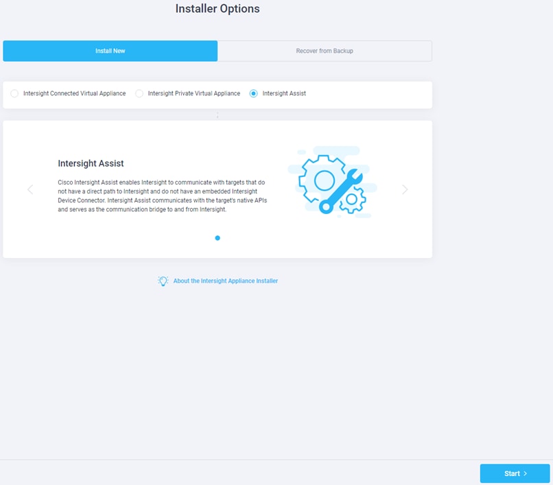
Step 18. Cisco Intersight Assist VM needs to be claimed in Cisco Intersight using the Device ID and Claim Code information visible in the GUI.
Step 19. Log into Cisco Intersight and connect to the appropriate account.
Step 20. From Cisco Intersight, select System, then click Administration > Targets.
Step 21. Click Claim a New Target. Select Cisco Intersight Assist and click Start.
Step 22. Copy and paste the Device ID and Claim Code shown in the Intersight Assist web interface to the Cisco Intersight Device Claim window.
Step 23. Select the Resource Group and click Claim.
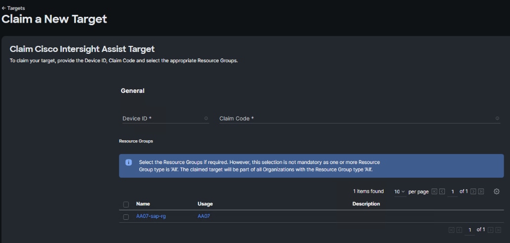
Note: Intersight Assist will now appear as a claimed device.
Step 24. In the Intersight Assist web interface, verify that Intersight Assist is Connected Successfully and click Continue.
Note: The Cisco Intersight Assist software will now be downloaded and installed into the Intersight Assist VM. This can take up to an hour to complete.
Note: When the software download is complete, an Intersight Assist login screen will appear.
Step 25. Log into Intersight Assist with the admin user and the password supplied in the OVA installation. Check the Intersight Assist status and log out of Intersight Assist.
Claim VMware vCenter using Cisco Intersight Assist Appliance
Procedure 1. Claim the vCenter from Cisco Intersight
Step 1. Log into Cisco Intersight and connect to the account for this FlexPod.
Step 2. Select System > Administration > Targets and click Claim a New Target.
Step 3. Under Select Target Type, select VMware vCenter under Hypervisor and click Start.
Step 4. In the VMware vCenter window, verify the correct Intersight Assist is selected.
Step 5. Fill in the vCenter information. If Intersight Workflow Optimizer (IWO) is used, turn on Datastore Browsing Enabled and Guest Metrics Enabled. If it is desired to use Hardware Support Manager (HSM) to be able to upgrade IMM server firmware from VMware Lifecycle Manager, turn on HSM. Click Claim.
Note: It is recommended to use an admin-level user other than administrator@vsphere.local to claim VMware vCenter to Intersight. The administrator@vsphere.local user has visibility to the vSphere Cluster Services (vCLS) virtual machines. These virtual machines would then be visible in Intersight and Intersight operations could be executed on them. VMware does not recommend users executing operations on these VMs. Using a user other than administrator@vsphere.local would make the vCLS virtual machines inaccessible from Cisco Intersight.
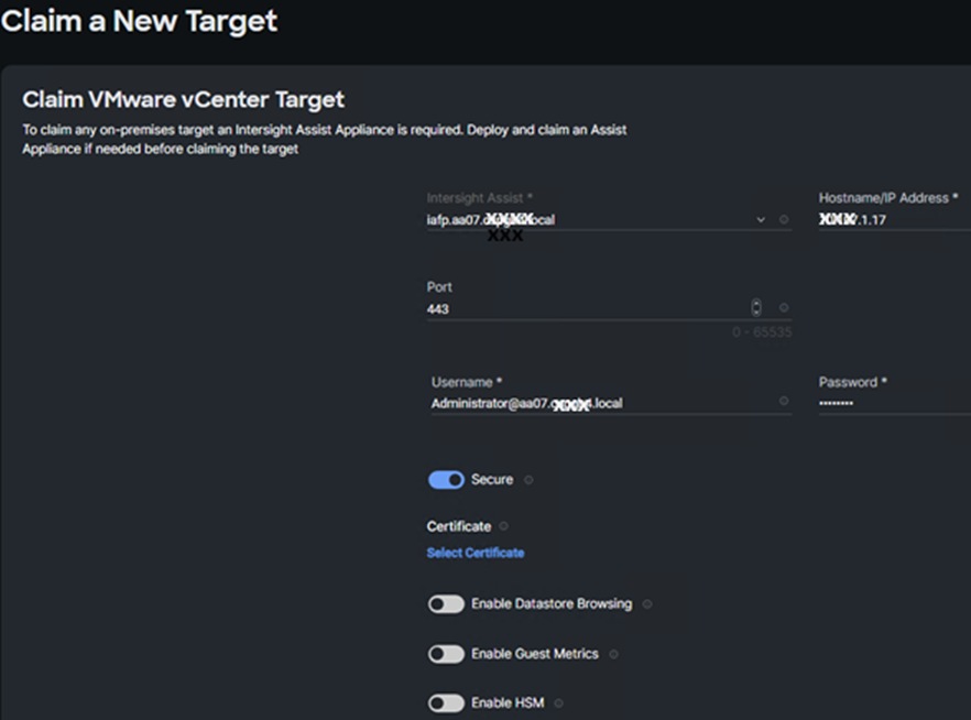
Step 6. After a few minutes, the VMware vCenter will show Connected in the Targets list and will also appear under Infrastructure Service > Operate > Virtualization.
Step 7. Detailed information obtained from the vCenter can now be viewed by clicking Infrastructure Service > Operate > Virtualization and selecting the Datacenters tab. Other VMware vCenter information can be obtained by navigating through the Virtualization tabs.
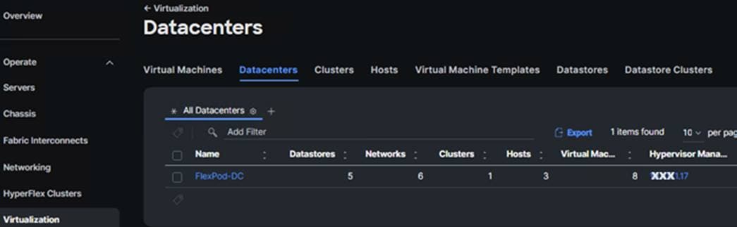
Procedure 2. Interact with Virtual Machines
VMware vCenter integration with Cisco Intersight allows you to directly interact with the virtual machines (VMs) from the Cisco Intersight dashboard. In addition to obtaining in-depth information about a VM, including the operating system, CPU, memory, host name, and IP addresses assigned to the virtual machines, you can use Cisco Intersight to perform the following actions on the virtual machines:
● Start/Resume
● Stop
● Soft Stop
● Suspend
● Reset
● Launch VM Console
Step 1. Log into Cisco Intersight and connect to the account for this FlexPod.
Step 2. Select Infrastructure Service > Operate > Virtualization.
Step 3. Click the Virtual Machines tab.
Step 4. Click “…” next to a VM and select from the various VM options.
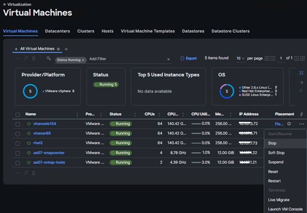
Step 5. To gather more information about a VM, click a VM name. The same interactive options are available under Actions.
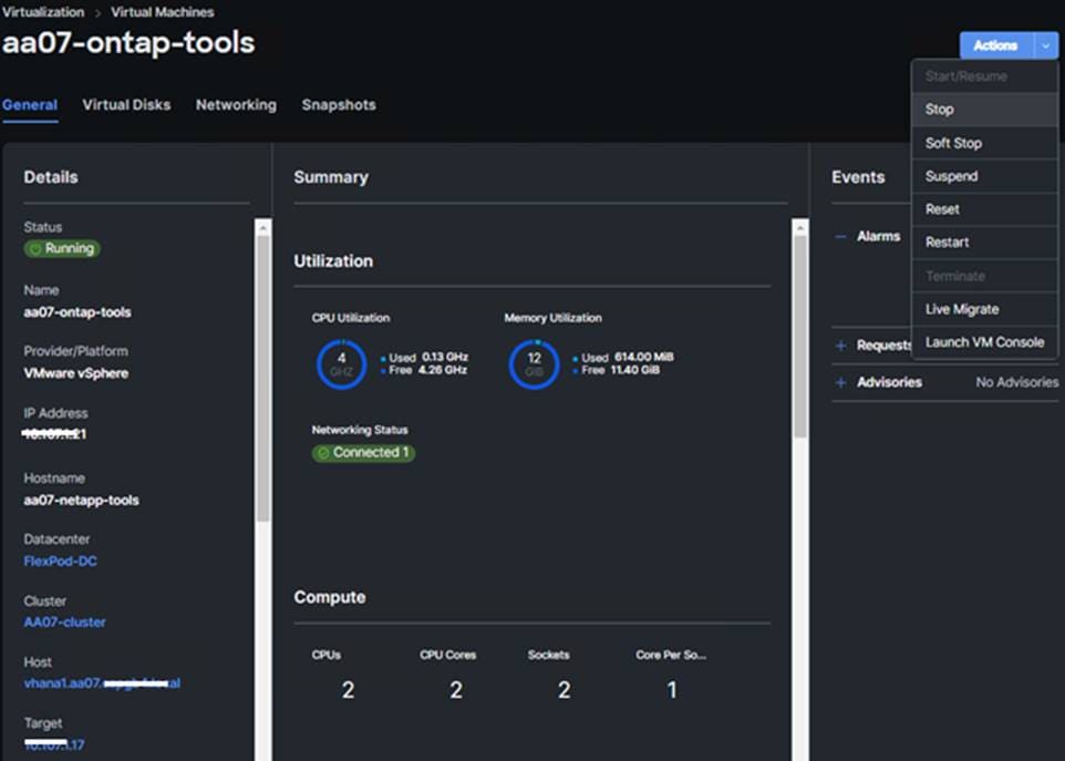
Claim NetApp Active IQ Manager using Cisco Intersight Assist Appliance
Procedure 1. Manually Claim the NetApp Active IQ Unified Manager into Cisco Intersight
Step 1. Log into Cisco Intersight and connect to the account for this FlexPod.
Step 2. From Cisco Intersight, click System > Administration > Targets.
Step 3. Click Claim a New Target. In the Select Target Type window, select NetApp Active IQ Unified Manager under Storage and click Start.
Step 4. In the Claim NetApp Active IQ Unified Manager Target window, verify the correct Intersight Assist is selected.
Step 5. Fill in the NetApp Active IQ Unified Manager information and click Claim.
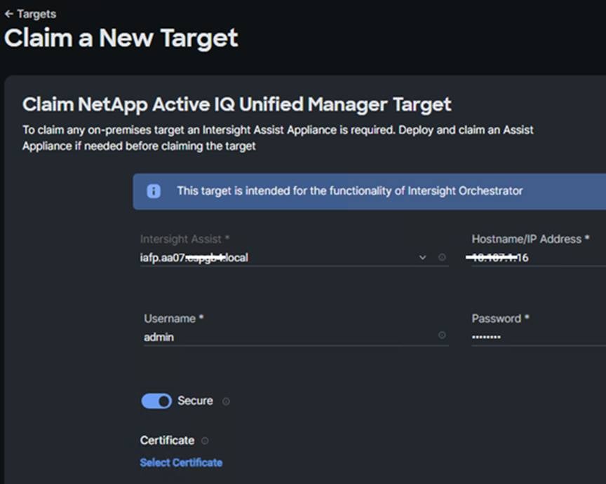
Step 6. After a few minutes, the NetApp ONTAP Storage configured in the Active IQ Unified Manager will appear under Infrastructure Service > Operate > Storage tab.
Step 7. Click the storage cluster name to see detailed General, Inventory, and Checks information on the storage.
Step 8. Click My Dashboard > Storage to see storage monitoring widgets.
Claim Cisco Nexus Switches using Cisco Intersight Assist Appliance
Procedure 1. Claim Cisco Nexus Switches
Step 1. Log into Cisco Intersight and connect to the account for this FlexPod.
Step 2. From Cisco Intersight, click System > Administration > Targets.
Step 3. Click Claim a New Target. In the Select Target Type window, select Cisco Nexus Switch under Network and click Start.
Step 4. In the Claim Cisco Nexus Switch Target window, verify the correct Intersight Assist is selected.
Step 5. Fill in the Cisco Nexus Switch information and click Claim.
Note: You can use the admin user on the switch.
Step 6. Repeat steps 1 - 5 to add the second Cisco Nexus Switch.
After a few minutes, the two switches will appear under Infrastructure Service > Operate > Networking > Ethernet Switches.
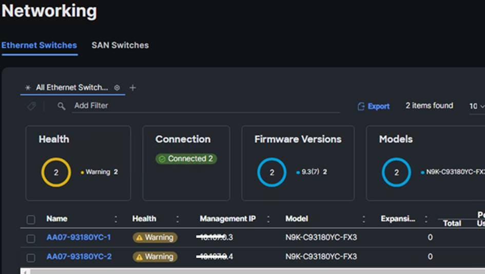
Step 7. Click one of the switch names to get detailed General and Inventory information on the switch.
Claim Cisco MDS Switches using Cisco Intersight Assist Appliance
Procedure 1. Claim Cisco MDS Switches (if they are part of the FlexPod)
Step 1. Log into Cisco Intersight and connect to the account for this FlexPod.
Step 2. From Cisco Intersight, click System > Administration > Targets.
Step 3. Click Claim a New Target. In the Select Target Type window, select Cisco MDS Switch under Network and click Start.
Step 4. In the Claim Cisco MDS Switch Target window, verify the correct Intersight Assist is selected.
Step 5. Fill in the Cisco MDS Switch information including use of Port 8443 and click Claim.
Note: You can use the admin user on the switch.
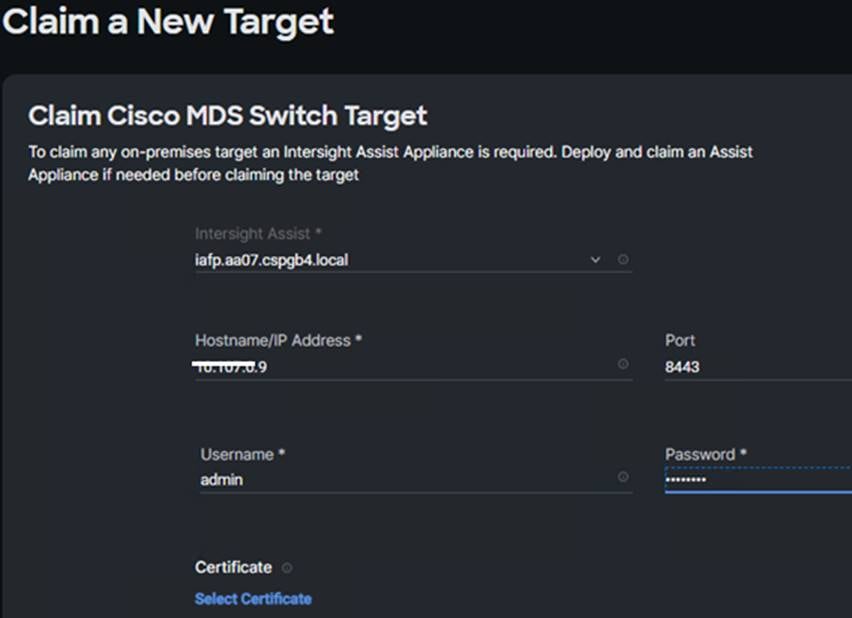
Step 6. Repeat steps 1 - 5 to add the second Cisco MDS Switch.
After a few minutes, the two switches will appear under Infrastructure Service > Operate > Networking > SAN Switches.
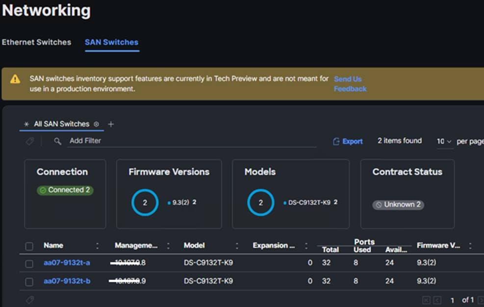
Step 7. Click one of the switch names to get detailed General and Inventory information on the switch.
Pramod Ramamurthy, Technical Marketing Engineer, Cloud and Compute Group, Cisco Systems GmbH.
Pramod is a Technical Marketing Engineer with Cisco Computing Systems Product Group’s UCS Solutions team. Pramod has over 20 years of experience in the IT industry focusing on SAP, SAP HANA, and Datacenter technologies. As part of Cisco’s SAP Business Unit in charge of Cisco UCS based SAP HANA Appliance build and validation and TDI solutions, Pramod focuses on the Converged Infrastructure Solutions design, validation, and associated collaterals build for SAP HANA.
Marco Schoen, Technical Marketing Engineer, NetApp, Inc.
Marco is a Technical Marketing Engineer with NetApp and has over 20 years of experience in the IT industry focusing on SAP technologies. His specialization areas include SAP NetWeaver Basis technology and SAP HANA. He is currently focusing on the SAP HANA infrastructure design, validation and certification on NetApp Storage solutions and products including various server technologies.
Acknowledgements
For their support and contribution to the design, validation, and creation of this Cisco Validated Design, the authors would like to thank:
● John George, Technical Marketing Engineer, Cisco Systems, Inc.
● Haseeb Niazi, Principal Technical Marketing Engineer, Cisco Systems, Inc.
For comments and suggestions about this guide and related guides, join the discussion on Cisco Community at https://cs.co/en-cvds.
ALL DESIGNS, SPECIFICATIONS, STATEMENTS, INFORMATION, AND RECOMMENDATIONS (COLLECTIVELY, "DESIGNS") IN THIS MANUAL ARE PRESENTED "AS IS," WITH ALL FAULTS. CISCO AND ITS SUPPLIERS DISCLAIM ALL WARRANTIES, INCLUDING, WITHOUT LIMITATION, THE WARRANTY OF MERCHANTABILITY, FITNESS FOR A PARTICULAR PURPOSE AND NONINFRINGEMENT OR ARISING FROM A COURSE OF DEALING, USAGE, OR TRADE PRACTICE. IN NO EVENT SHALL CISCO OR ITS SUPPLIERS BE LIABLE FOR ANY INDIRECT, SPECIAL, CONSEQUENTIAL, OR INCIDENTAL DAMAGES, INCLUDING, WITHOUT LIMITATION, LOST PROFITS OR LOSS OR DAMAGE TO DATA ARISING OUT OF THE USE OR INABILITY TO USE THE DESIGNS, EVEN IF CISCO OR ITS SUPPLIERS HAVE BEEN ADVISED OF THE POSSIBILITY OF SUCH DAMAGES.
THE DESIGNS ARE SUBJECT TO CHANGE WITHOUT NOTICE. USERS ARE SOLELY RESPONSIBLE FOR THEIR APPLICATION OF THE DESIGNS. THE DESIGNS DO NOT CONSTITUTE THE TECHNICAL OR OTHER PROFESSIONAL ADVICE OF CISCO, ITS SUPPLIERS OR PARTNERS. USERS SHOULD CONSULT THEIR OWN TECHNICAL ADVISORS BEFORE IMPLE-MENTING THE DESIGNS. RESULTS MAY VARY DEPENDING ON FACTORS NOT TESTED BY CISCO.
CCDE, CCENT, Cisco Eos, Cisco Lumin, Cisco Nexus, Cisco StadiumVision, Cisco TelePresence, Cisco WebEx, the Cisco logo, DCE, and Welcome to the Human Network are trademarks; Changing the Way We Work, Live, Play, and Learn and Cisco Store are service marks; and Access Registrar, Aironet, AsyncOS, Bringing the Meeting To You, Catalyst, CCDA, CCDP, CCIE, CCIP, CCNA, CCNP, CCSP, CCVP, Cisco, the Cisco Certified Internetwork Expert logo, Cisco IOS, Cisco Press, Cisco Systems, Cisco Systems Capital, the Cisco Systems logo, Cisco Unified Computing System (Cisco UCS), Cisco UCS B-Series Blade Servers, Cisco UCS C-Series Rack Servers, Cisco UCS S-Series Storage Servers, Cisco UCS Manager, Cisco UCS Management Software, Cisco Unified Fabric, Cisco Application Centric Infrastructure, Cisco Nexus 9000 Series, Cisco Nexus 7000 Series. Cisco Prime Data Center Network Manager, Cisco NX-OS Software, Cisco MDS Series, Cisco Unity, Collaboration Without Limitation, EtherFast, EtherSwitch, Event Center, Fast Step, Follow Me Browsing, FormShare, GigaDrive, HomeLink, Internet Quotient, IOS, iPhone, iQuick Study, LightStream, Linksys, MediaTone, MeetingPlace, MeetingPlace Chime Sound, MGX, Networkers, Networking Academy, Network Registrar, PCNow, PIX, PowerPanels, ProConnect, ScriptShare, SenderBase, SMARTnet, Spectrum Expert, StackWise, The Fastest Way to Increase Your Internet Quotient, TransPath, WebEx, and the WebEx logo are registered trade-marks of Cisco Systems, Inc. and/or its affiliates in the United States and certain other countries. (LDW_P2)
All other trademarks mentioned in this document or website are the property of their respective owners. The use of the word partner does not imply a partnership relationship between Cisco and any other company. (0809R)