FlashStack Datacenter for Oracle RAC 19c Databases on VMware vSphere
Available Languages
Bias-Free Language
The documentation set for this product strives to use bias-free language. For the purposes of this documentation set, bias-free is defined as language that does not imply discrimination based on age, disability, gender, racial identity, ethnic identity, sexual orientation, socioeconomic status, and intersectionality. Exceptions may be present in the documentation due to language that is hardcoded in the user interfaces of the product software, language used based on RFP documentation, or language that is used by a referenced third-party product. Learn more about how Cisco is using Inclusive Language.
- US/Canada 800-553-2447
- Worldwide Support Phone Numbers
- All Tools
 Feedback
 Feedback


In partnership with:
![]()
Document Organization
This document is organized into the following chapters:
| Chapter |
Description |
| High-level overview of the solution, benefits, and conclusion. |
|
| Provides the solution overview, intended audience, and new features |
|
| Provides the requirements, considerations, and performance details for the solution design |
|
| Provides the installation and configuration steps |
|
| Provides the OS and database deployment considerations and steps |
|
| Provides the tests implemented and results |
|
| Details the resiliency of the solution and the failure tests implemented |
|
| Summarizes the solution and its benefits |
|
| Provides information about known issues, enhancements, fixes, and recommendations |
|
| Provides a list of references used in this document |
|
| Provides details about the authors of this CVD |
|
| Additional configuration information and resources |
|
| Provide links for feedback and CVD Program information |
About the Cisco Validated Design Program
The Cisco Validated Design (CVD) program consists of systems and solutions designed, tested, and documented to facilitate faster, more reliable, and more predictable customer deployments. For more information, go to: http://www.cisco.com/go/designzone.
Icons Used in this Document
The IT industry has been transforming rapidly to converged infrastructure, which enables faster provisioning, scalability, lower data center costs, simpler management infrastructure with technology advancement. There is a current industry trend for pre-engineered solutions which standardize the data center infrastructure and offers operational efficiencies and agility to address enterprise applications and IT services. This standardized data center needs to be seamless instead of siloed when spanning multiple sites, delivering a uniform network and storage experience to the compute systems and end users accessing these data centers. Cisco Unified Computing System (Cisco UCS) is a next-generation data center platform that unites computing, network, storage access, and virtualization into a single cohesive system.
The FlashStack solution provides best of breed technology from Cisco Unified Computing System and Pure Storage to gain the benefits that converged infrastructure brings to the table. FlashStack solution provides the advantage of having the compute, storage, and network stack integrated with the programmability of Cisco Unified Computing System (Cisco UCS). Cisco Validated Designs (CVDs) consist of systems and solutions that are designed, tested, and documented to facilitate and improve customer deployments. These designs incorporate a wide range of technologies and products into a portfolio of solutions that have been developed to address the business needs of customers and to guide them from design to deployment. The combination of Cisco UCS, Pure Storage, Oracle Real Application Cluster Database and VMware vSphere architecture can accelerate your IT transformation by enabling faster deployments, greater flexibility of choice, efficiency, high availability, and lower risk.
This Cisco Validated Design (CVD) describes a FlashStack reference architecture for deploying a highly available Oracle Multitenant RAC 19c Databases environment on Pure Storage FlashArray//X90 R3 using Cisco UCS Compute Servers, Cisco Fabric Interconnect Switches, Cisco Nexus Switches, Cisco MDS Switches with VMware vSphere and Red Hat Enterprise Linux. Cisco and Pure Storage have validated the reference architecture with various Database workloads like OLTP (Online Transactional Processing) and Data Warehouse in Cisco’s UCS Datacenter lab. This document presents the hardware and software configuration of the components involved, results of various tests performed and offers a framework for implementing highly available Oracle RAC Databases and best practices guidance.
This chapter is organized into the following subjects:
| Chapter |
Subject |
| Solution Overview |
This Cisco Validated Design (CVD) describes how Cisco Unified Computing System (Cisco UCS) with the new Cisco UCS B200 M6 blade servers, can be used in conjunction with Pure Storage FlashArray//X90 R3 System to implement a mission-critical application such as an Oracle Multitenant Real Application Cluster (RAC) 19c Database solution using VMware vSphere 7.0 on Fibre-Channel based storage access.
The Oracle Multitenant architecture helps customers reduce IT costs by simplifying consolidation, provisioning, upgrades and more. The Oracle Multitenant architecture allows Container database to hold many pluggable databases and it fully complements other options, including Oracle Real Application Clusters and Oracle Active Data Guard. Organizations of all kinds rely on their relational databases for both transaction processing (OLTP) and analytics (OLAP), but many still have challenges in meeting their goals of high availability, security, and performance.
FlashStack embraces the latest technology and efficiently simplifies data center workloads that redefine the way IT delivers value:
● A cohesive, integrated system that is managed, serviced, and tested as a whole.
● Guarantee customer success with prebuilt, pre-tested drivers and Oracle database software.
● Faster Time to Deployment – Leverage a pre-validated platform to minimize business disruption, improve IT agility, and reduce deployment time from months to weeks.
● Reduces Operational Risk – Highly available architecture with no single point of failure, non-disruptive operations, and no downtime.
The intended audience for this document includes, but is not limited to, sales engineers, field consultants, database administrators, IT managers, Oracle database architects, and customers who want to deploy an Oracle RAC 19c database solution on the FlashStack Converged Infrastructure with Pure Storage FlashArray, Cisco UCS platform and VMWare vSphere. A working knowledge of Oracle RAC Database, Linux, VMware, Storage technology, and Network is assumed but is not a prerequisite to read this document.
This document provides a step-by-step configuration and implementation guide for the FlashStack Datacenter with Cisco UCS Compute Servers, Cisco Fabric Interconnect Switches, Cisco MDS Switches, Cisco Nexus Switches and Pure Storage FlashArray Storage to deploy an Oracle RAC Database solution on VMWare vSphere environment.
The following are the objectives of this reference document:
● Provide reference architecture design guidelines for deploying Oracle RAC Databases on Virtual Server Infrastructures.
● Highlight the performance, manageability, and high availability for OLTP and OLAP type of Oracle Databases on the FlashStack CI Solution.
● Demonstrate the seamless scalability to meet growth needs of Oracle Databases.
● Confirm high availability of Database instances, without performance compromise through software and hardware failures.
In this solution, we will deploy both types of databases (Non-Container Database and Container Database) and perform testing on various types of workloads to check how performance on both aspects of it. We will demonstrate the scalability and performance of this solution by running database stress tests such as SwingBench and SLOB (Silly Little Oracle Benchmark) on OLTP (Online Transaction Processing) and DSS (Decision Support System) databases with varying users, nodes, and read/write workload characteristics.
This release introduces the Pure Storage FlashArray//X90 R3 that brings the low latency and high performance of NVMe technology to the storage network along with Cisco UCS B200 M6 Blade Servers (6th Generation) to deploy Oracle RAC Database Release 19c, using traditional Fibre Channel on VMware and Red Hat Enterprise Linux.
It incorporates the following features:
● Cisco UCS B200 M6 Blade Servers with 3rd Gen Intel Xeon Scalable Processors
● Validation of Oracle RAC 19c Container and Non-Container Database deployments
● Support for the Cisco UCS Infrastructure and UCS Manager Software Release 4.2(1i)
● Support for Purity 6.1.11
● Validation of VMware vSphere 7.0.2
The FlashStack platform, developed by Cisco and Pure Storage, is a flexible, integrated infrastructure solution that delivers pre-validated storage, networking, and server technologies. Composed of defined set of hardware and software, this FlashStack solution is designed to increase IT responsiveness to organizational needs and reduce the cost of computing with maximum uptime and minimal risk. Cisco and Pure Storage have carefully validated and verified the FlashStack solution architecture and its many use cases while creating a portfolio of detailed documentation, information, and references to assist customers in transforming their data centers to this shared infrastructure model.
This portfolio includes, but is not limited to, the following items:
● Best practice architectural design
● Implementation and deployment instructions and provides application sizing based on results
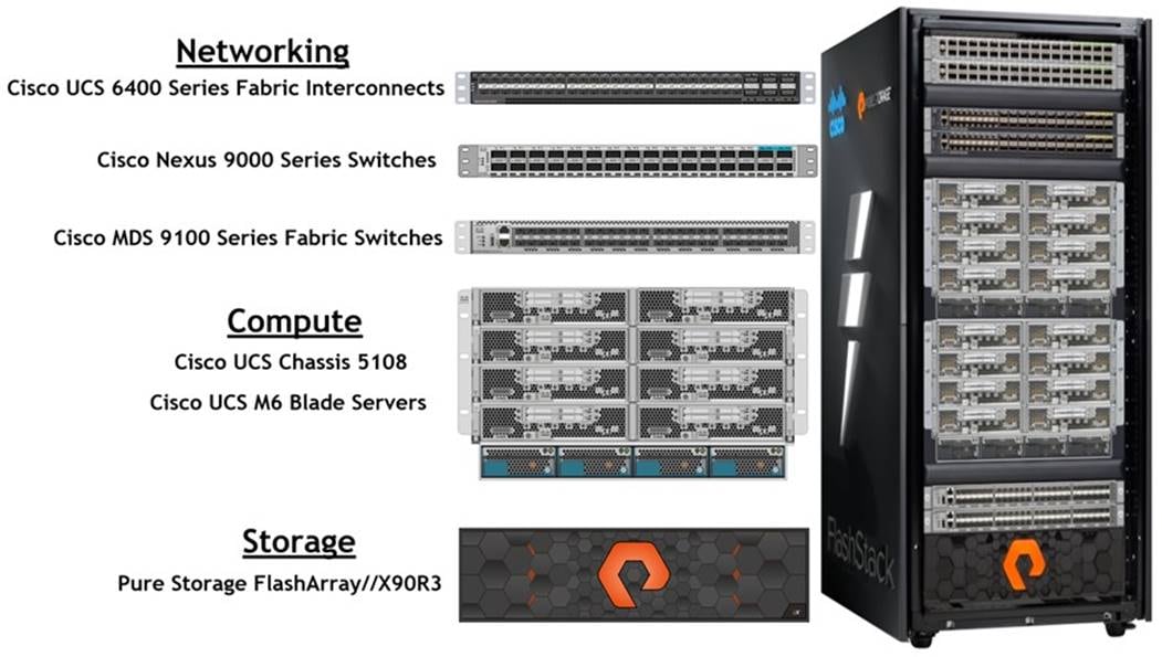
As shown in Figure 1, these components are connected and configured according to best practices of both Cisco and Pure Storage and provides the ideal platform for running a variety of enterprise database workloads with confidence. FlashStack can scale up for greater performance and capacity (adding compute, network, or storage resources individually as needed), or it can scale out for environments that require multiple consistent deployments.
The reference architecture explained in this document leverages the Pure Storage FlashArray//X90 R3 Controller with NVMe based DirectFlash Fabric for Storage, Cisco UCS B200 M6 Blade Server for Compute, Cisco Nexus 9000 Series Switches for the networking element, Cisco MDS 9000 Series Switches for the SAN Storage Networking element, and Cisco Fabric Interconnects 6400 series for System Management. As shown in Figure 1, FlashStack Architecture can maintain consistency at scale. Each of the component families shown in (Cisco UCS, Cisco Nexus, Cisco MDS, Cisco FI, and Pure Storage) offers platform and resource options to scale the infrastructure up or down, while supporting the same features and functionality that are required under the configuration and connectivity best practices of FlashStack.
FlashStack provides a jointly supported solution by Cisco and Pure Storage. Bringing a carefully validated architecture built on superior compute, world-class networking, and the leading innovations in all flash storage. The portfolio of validated offerings from FlashStack includes but is not limited to the following:
● Consistent Performance and Scalability
● Operational Simplicity
● Mission Critical and Enterprise Grade Resiliency
Cisco and Pure Storage have also built a robust and experienced support team focused on FlashStack solutions, from customer account and technical sales representatives to professional services and technical support engineers. The support alliance between Pure Storage and Cisco gives customers and channel services partners direct access to technical experts who collaborate with cross vendors and have access to shared lab resources to resolve potential issues.
This chapter is organized into the following subjects:
| Chapter |
Subject |
| Solution Design |
The reference FlashStack architecture covered in this document is built on the Pure Storage FlashArray//X90 R3 Series for Storage, Cisco B200 M6 Blade Servers for Compute, Cisco Nexus 9336C-FX2 Switches, Cisco MDS 9148T Fibre Channel Switches and Cisco Fabric Interconnects 6454 Fabric Interconnects for System Management in a single package. The design is flexible enough that the networking, computing, and storage can fit in one data center rack or be deployed according to a customer's data center design. The reference architecture reinforces the "wire-once" strategy, because as additional storage is added to the architecture, no re-cabling is required from the hosts to the Cisco UCS fabric interconnect.
The processing capabilities of CPUs have increased much faster than the processing demands of most database workloads. Sometimes databases are limited by CPU work, but it is generally a result of the processing limits of a single core and is not a limitation of the CPU. The result is an increasing number of idle cores on database servers that still must be licensed for the Oracle Database software. This underutilization of CPU resources is a waste of capital expenditure, not only in terms of licensing costs, but also in terms of the cost of the server itself, heat output, and so on. The Cisco UCS servers comes with different CPU options in terms of higher clock-speed which would help the database workloads and customer will have the option of using Higher clock-speed CPU with lower cores to keep the Oracle licensing costs down.
Requirements
This subject is organized into the following sections:
| Subject |
Section |
| Requirements |
This section describes the hardware and software components used to deploy an eight node Oracle RAC 19c Database solution on this architecture.
The inventory of the components used in this solution architecture is listed in Table 1.
Table 1. Hardware Inventory and Bill of Material
| Name |
Model/Product ID |
Description |
Quantity |
| Cisco UCS Blade Server Chassis |
UCSB-5108-AC2 |
Cisco UCS AC Blade Server Chassis, 6U with Eight Blade Server Slots |
2 |
| Cisco UCS Fabric Extender |
UCS-IOM-2408 |
Cisco UCS 2408 8x25 Gb Port IO Module |
4 |
| Cisco UCS B200 M6 Blade Server |
UCSB-B200-M6 |
Cisco UCS B200 M6 2 Socket Blade Server |
8 |
| Cisco UCS VIC 1440 |
UCSB-MLOM-40G-04 |
Cisco UCS VIC 1440 Blade MLOM |
8 |
| Cisco UCS Port Expander Card |
UCSB-MLOM-PT-01 |
Port Expander Card for Cisco UCS MLOM |
8 |
| Cisco UCS 6454 Fabric Interconnect |
UCS-FI-6454 |
Cisco UCS 6454 Fabric Interconnect |
2 |
| Cisco Nexus Switch |
N9K-9336C-FX2 |
Cisco Nexus 9336C-FX2 Switch |
2 |
| Cisco MDS Switch |
DS-C9148T-24PETK9 |
Cisco MDS 9148T 32-Gbps 48-Port Fibre Channel Switch |
2 |
| Pure Storage FlashArray |
FA-X90 R3 |
Pure Storage FlashArray//X90 R3 |
1 |
In this solution design, eight identical Cisco UCS B200 M6 Blade Servers were used for hosting an eight node Oracle RAC Database. The Cisco UCS B200 M6 two socket blade server is half-width blade server with two sockets, up to 32 DIMMs, two drive bays, two NVMe slots, Intel Xeon Processor Scalable Family, one mLOM, and two Mezz slots. The Cisco UCS B200 M6 Server configuration is listed in Table 2.
Table 2. Cisco UCS B200 M6 Blade Server
| Cisco UCS B200 M6 2 Socket Blade Server Configuration |
||
| Processor |
2 x Intel(R) Xeon(R) Gold 6348 2.60 GHz 235W 28C 42.00MB Cache DDR4 3200MHz 6TB |
UCS-CPU-I6348 |
| Memory |
16 x Samsung 32GB RDIMM DRx4 3200 |
UCS-MR-X32G2RW |
| Cisco UCS VIC 1440 |
Cisco UCS VIC 1440 Blade MLOM |
UCSB-MLOM-40G-04 |
| Cisco UCS Port Expander Card |
Port Expander Card for Cisco UCS MLOM |
UCSB-MLOM-PT-01 |
| Storage Controller |
Cisco FlexStorage 12G SAS RAID Controller. Supports RAID levels 0, 1, 10 and JBOD. Supports SSD (solid state drives) |
UCSB-RAID12G-M6 |
| SSD Disk |
480GB 2.5-inch Enterprise Value 6G SATA SSD |
UCS-SD480GBKS4-EV |
In this solution, six vNICs and four vHBAs were configured on each host to carry all the network and storage traffic as listed in Table 3.
Table 3. vNIC and vHBA Configured on each Linux Host
| vNIC Details |
|
| vNIC 0 (eth0) |
ESXi Management Network Traffic Interface on Fabric Interconnect – A (Allowed VLAN 134) MTU = 1500 |
| vNIC 1 (eth1) |
ESXi Management Network Traffic Interface on Fabric Interconnect – B (Allowed VLAN 134) MTU = 1500 |
| vNIC 2 (eth2) |
VM Management and vMotion Network Traffic Interface on Fabric Interconnect – A (Allowed VLAN 2, 11 & 135) MTU = 9000 |
| vNIC 3 (eth3) |
VM Management and vMotion Network Traffic Interface on Fabric Interconnect – B (Allowed VLAN 2, 11 & 135) MTU = 9000 |
| vNIC 4 (eth4) |
Private Server-to-Server Network (Cache Fusion) Traffic Interface for Oracle RAC on Fabric Interconnect – A (Allowed VLAN 2 & 10) MTU = 9000 |
| vNIC 5 (eth5) |
Private Server-to-Server Network (Cache Fusion) Traffic Interface for Oracle RAC on Fabric Interconnect – B (Allowed VLAN 2 & 10) MTU = 9000 |
| vHBA0 |
FC Network (Oracle RAC Storage) Traffic on Fabric Interconnect – A to MDS-A Switch |
| vHBA1 |
FC Network (Oracle RAC Storage) Traffic on Fabric Interconnect – B to MDS-B Switch |
| vHBA2 |
FC Network (Oracle RAC Storage) Traffic on Fabric Interconnect – A to MDS-A Switch |
| vHBA3 |
FC Network (Oracle RAC Storage) Traffic on Fabric Interconnect – B to MDS-B Switch |
The vNICs are configured for redundancy and failover on both the Fabric Interconnects and ESXi as listed in Table 4.
Table 4. vNIC and vHBA Configured on Each Linux Host
| Server vNICs |
FI |
Redundancy |
MTU |
Switch Type |
ESXi Failover |
| vNIC 0 |
FI – A |
Primary |
1500 |
vSwitch-0 |
ACTIVE |
| vNIC 1 |
FI – B |
Secondary |
ACTIVE |
||
| vNIC 2 |
FI – A |
Primary |
9000 |
vDS-0 |
ACTIVE |
| vNIC 3 |
FI – B |
Secondary |
ACTIVE |
||
| vNIC 4 |
FI – A |
Primary |
9000 |
vDS-1 |
ACTIVE |
| vNIC 5 |
FI – B |
Secondary |
ACTIVE |
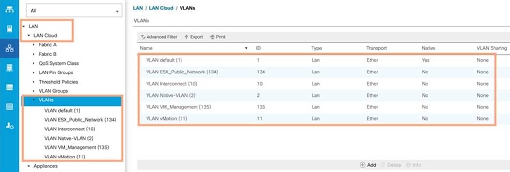
For this solution, five VLANs were configured to carry ESXi Management, VM Management, vMotion, and Oracle RAC private network traffic, as well as two VSANs to carry FC storage traffic, as listed in Table 5.
Table 5. VLAN and VSAN Configuration
| VLAN and VSAN Configuration |
||
| VLAN |
||
| Name |
ID |
Description |
| Native VLAN |
2 |
Native VLAN |
| ESXi Management Network |
134 |
VLAN for ESXi Management Network Traffic |
| VM Management |
135 |
VLAN for VM Management Network Traffic |
| Interconnect |
10 |
VLAN for Private Server-to-Server Network (Cache Fusion) Traffic for Oracle RAC |
| vMotion & Backup |
11 |
VLAN for vMotion and Database Backup Network Traffic |
| VSAN |
||
| Name |
ID |
Description |
| VSAN-A |
151 |
FC Network (Oracle RAC Storage) Traffic through Fabric Interconnect A |
| VSAN-B |
152 |
FC Network (Oracle RAC Storage) Traffic through Fabric Interconnect B |
This FlashStack solution consist of FlashArray //X90R3 Storage as listed in Table 6.
Table 6. Pure Storage FlashArray //X90 R3 Storage Configuration
| Storage Components |
Description |
| FlashArray//X90 R3 |
Pure Storage FlashArray//X90 R3 |
| Capacity |
27.26 TB |
| Connectivity |
8 x 32 Gb/s redundant FC, 1 Gb/s redundant Ethernet (Management port) |
| Physical |
3 Rack Units |
Table 7 lists the versions of the software and firmware releases used in this FlashStack solution.
Table 7. Software and Firmware Revisions
| Software and Firmware |
Version |
| Cisco Nexus 9336C-FX2 NXOS |
NXOS 9.3(2) |
| Cisco MDS 9148T System |
System Version 8.4(2c) |
| Cisco UCS Manager System |
4.2(1i) |
| Cisco UCS Adapter VIC 1440 |
Package Version – 4.2 (1i)B Running Version – 5.2 (1b) |
| Pure Storage FlashArray //X90R3 |
Purity//FA 6.1.11 |
| VMware vSphere ESXi Cisco Custom ISO |
VMware ESXi, 7.0.2, 17630552 |
| Virtual Machine OS |
Red Hat Enterprise Linux 7.9 (64-bit) |
| Cisco UCS VIC Storage Driver for VMWare Driver for ESXi_7.0U2 esxcli software vib list |grep nfnic |
Cisco_bootbank_nfnic_4.0.0.71-1OEM.670.0.0.8169922.vib 4.0.0.71-1OEM.670.0.0.8169922 |
| Cisco UCS VIC Network Driver for VMWare Driver for ESXi_7.0U2 esxcli software vib list |grep nenic |
Cisco_bootbank_nenic_1.0.35.0-1OEM.670.0.0.8169922.vib 1.0.35.0-1OEM.670.0.0.8169922 |
| VMware vCenter |
7.0 |
| Oracle Database 19c Grid Infrastructure for Linux x86-64 |
19.12.0.0.0 |
| Oracle Database 19c Enterprise Edition for Linux x86-64 |
19.12.0.0.0 |
| FIO |
fio-3.7-3.el8.x86_64 |
| Oracle SwingBench |
2.5.971 |
| SLOB |
2.5.2.4 |
Physical Topology
This solution consists of the following set of hardware combined into a single stack:
● Compute: Cisco UCS B200 M6 Blade Servers with Cisco Virtual Interface Cards (VICs) 1440
● Network: Cisco Nexus 9336C-FX2, Cisco MDS 9148T Fibre Channel and Cisco UCS Fabric Interconnect 6454 for network and management connectivity
● Storage: Pure Storage FlashArray//X90 R3
In this solution design, two Cisco UCS 5108 Blade Server Chassis with eight identical Intel Xeon CPU-based Cisco UCS B200 M6 Blade Servers for hosting the 8-Node Oracle RAC Databases were deployed. The Cisco UCS B200 M6 Server has a Virtual Interface Card (VIC) 1440 with a port expander and they were connected to eight ports from each Cisco Fabric extender 2408 from the Cisco UCS Chassis to the Cisco Fabric Interconnects. These were connected to the Cisco MDS Switches for upstream SAN connectivity to access the Pure FlashArray storage.
Figure 2 shows the architecture diagram of the FlashStack components deploying an eight node Oracle RAC 19c Database solution. This reference design is a typical network configuration that can be deployed in a customer's environments.
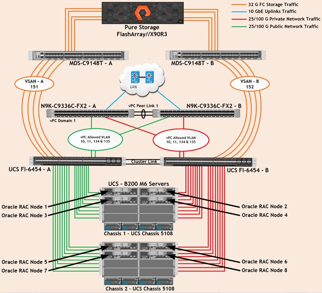
As shown in Figure 2, a pair of Cisco UCS 6454 Fabric Interconnects (FI) carries both storage and network traffic from the Cisco UCS B200 M6 server with the help of Cisco Nexus 9336C-FX2 and Cisco MDS 9132T switches. Both the Fabric Interconnects and the Cisco Nexus switches are clustered with the peer link between them to provide high availability.
Figure 2 shows 16 (8 x 25G link per chassis) links from the blade server chassis go to Fabric Interconnect – A. Similarly, 16 (8 x 25G link per chassis) links from the blade server chassis go to Fabric Interconnect – B. Fabric Interconnect – A links are used for Oracle Public Network Traffic (VLAN-134) shown as green lines while Fabric Interconnect – B links are used for Oracle Private Interconnect Traffic (VLAN- 10) shown as red lines. Two virtual Port-Channels (vPCs) are configured to provide public network and private network traffic paths for the server blades to northbound nexus switches.
FC Storage access from both Fabric Interconnects to MDS Switches and Pure Storage FlashArray are shown as orange lines. Four 32Gb links are connected from FI – A to MDS – A Switch. Similarly, four 32Gb links are connected from FI – B to MDS – B Switch. The Pure Storage FlashArray //X90R3 has eight active FC connection goes to the Cisco MDS Switches. Four FC ports are connected to MDS-A, and other four FC ports are connected to MDS-B Switch. The Pure Storage Controller CT0 and Controller CT1 SAN ports FC0 and FC8 are connected to MDS – A Switch while the Controller CT0 and Controller CT1 SAN ports FC1 and FC9 are connected to MDS – B Switch. Also, two FC Port-Channels (PC) are configured to provide storage network paths from the server blades to storage array. Each PC has VSANs created for application and storage network data access.
| Tech tip |
| For Oracle RAC configuration on Cisco Unified Computing System, we recommend keeping all private interconnects network traffic local on a single Fabric interconnect. In such a case, the private traffic will stay local to that fabric interconnect and will not be routed via northbound network switch. In that way, all the inter server blade (or RAC node private) communications will be resolved locally at the fabric interconnects and this significantly reduces latency for Oracle Cache Fusion traffic. |
Additional 1Gb management connections are needed for an out-of-band network switch that sits apart from this FlashStack infrastructure. Each UCS FI, MDS and Nexus switch is connected to the out-of-band network switch, and each Pure Storage controller also has two connections to the out-of-band network switch.
Although this is the base design, each of the components can be scaled easily to support specific business requirements. For example, more servers or even blade chassis can be deployed to increase compute capacity, additional disk shelves can be deployed to improve I/O capability and throughput, and special hardware or software features can be added to introduce new features. This document guides you through the detailed steps for deploying the base architecture, as shown in the above figure. These procedures cover everything from physical cabling to network, compute, and storage device configurations.
This chapter is organized into the following subjects:
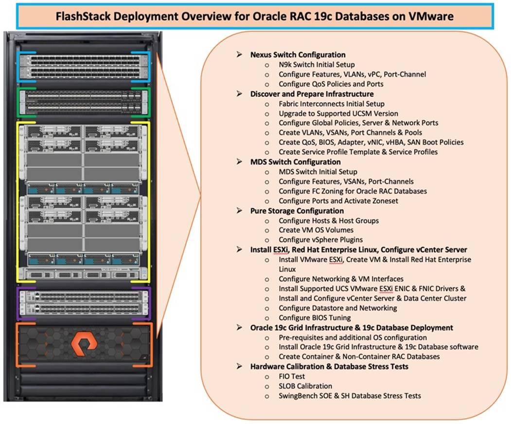
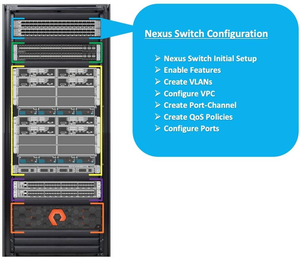
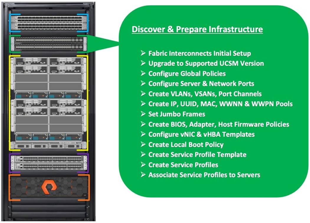
Figure 3 illustrates the high-level overview and steps for configuring various components to deploy and test the Oracle RAC Database 19c on FlashStack reference architecture.
Cisco Nexus Switch Configuration
This section details the high-level steps to configure Cisco Nexus Switches as shown in Figure 4.
The following procedures describe how to configure the Cisco Nexus switches for use in a base FlashStack environment. This procedure assumes you’re using Cisco Nexus 9336C-FX2 switches deployed with the 100Gb end-to-end topology.
Procedure 1. Initial Setup – Cisco Nexus A and B Switch
Note: On initial boot and connection to the serial or console port of the switch, the NX-OS setup should automatically start and attempt to enter Power on Auto Provisioning.
Step 1. Set up the initial configuration for the Cisco Nexus A switch on <nexus-A-hostname>, by running the following:
Abort Power on Auto Provisioning and continue with normal setup? (yes/no) [n]: yes
Do you want to enforce secure password standard (yes/no) [y]: Enter
Enter the password for "admin": <password>
Confirm the password for "admin": <password>
Would you like to enter the basic configuration dialog (yes/no): yes
Create another login account (yes/no) [n]: Enter
Configure read-only SNMP community string (yes/no) [n]: Enter
Configure read-write SNMP community string (yes/no) [n]: Enter
Enter the switch name: <nexus-A-hostname>
Continue with Out-of-band (mgmt0) management configuration? (yes/no) [y]: Enter
Mgmt0 IPv4 address: <nexus-A-mgmt0-ip>
Mgmt0 IPv4 netmask: <nexus-A-mgmt0-netmask>
Configure the default gateway? (yes/no) [y]: Enter
IPv4 address of the default gateway: <nexus-A-mgmt0-gw>
Configure advanced IP options? (yes/no) [n]: Enter
Enable the telnet service? (yes/no) [n]: Enter
Enable the ssh service? (yes/no) [y]: Enter
Type of ssh key you would like to generate (dsa/rsa) [rsa]: Enter
Number of rsa key bits <1024-2048> [1024]: Enter
Configure the ntp server? (yes/no) [n]: y
NTP server IPv4 address: <global-ntp-server-ip>
Configure default interface layer (L3/L2) [L3]: L2
Configure default switchport interface state (shut/noshut) [noshut]: Enter
Configure CoPP system profile (strict/moderate/lenient/dense/skip) [strict]: Enter
Would you like to edit the configuration? (yes/no) [n]: Enter
Step 2. Repeat Step 1 to setup the initial configuration for the Cisco Nexus B Switch and change the relevant switch hostname and management IP address.
Procedure 2. Configure Global Settings
Step 1. Login as admin user on the Cisco Nexus Switch A and run the following commands to set the global configurations on Switch A:
configure terminal
feature interface-vlan
feature hsrp
feature lacp
feature vpc
feature udld
feature lldp
spanning-tree port type network default
spanning-tree port type edge bpduguard default
port-channel load-balance src-dst l4port
policy-map type network-qos jumbo
class type network-qos class-default
mtu 9216
system qos
service-policy type network-qos jumbo
vrf context management
ip route 0.0.0.0/0 10.29.135.1
copy run start
Step 2. Repeat Step 1 for the Cisco Nexus Switch B and run the commands to set global configurations on Cisco Nexus Switch B.
Note: Make sure to run copy run start to save the configuration on each switch after the configuration is completed.
Procedure 3. VLAN Configuration
Note: Follow these steps on Cisco Nexus A and B Switches.
Step 1. Login as admin user on Cisco Nexus Switch A.
Step 2. Create VLAN 10 for Oracle RAC Private Network Traffic, VLAN 11 for vMotion, VLAN 134 for ESXi Management and VLAN 135 for VM Management and Oracle RAC Public Network Traffic:
configure terminal
vlan 2
name Native_VLAN
no shutdown
vlan 10
name Oracle_RAC_Private_Network
no shutdown
vlan 11
name vMotion
no shutdown
vlan 134
name ESX_Public_Network
no shutdown
vlan 135
name Oracle_RAC_Public_Network
no shutdown
interface Ethernet1/29
description connect to uplink switch
switchport access vlan 134
speed 1000
interface Ethernet1/31
description connect to uplink switch
switchport access vlan 135
speed 1000
copy run start
Step 3. Repeat Step 1 for the Cisco Nexus Switch B and create VLAN 10 for Oracle RAC Private Network Traffic, VLAN 11 for vMotion, VLAN 134 for ESXi Management and VLAN 135 for VM Management & Oracle RAC Public Network Traffic.
Note: Make sure to run copy run start to save the configuration on each switch after the configuration is completed.
Virtual Port Channel (vPC) for Network Traffic
A port channel bundles individual links into a channel group to create a single logical link that provides the aggregate bandwidth of up to eight physical links. If a member port within a port channel fails, traffic previously carried over the failed link switches to the remaining member ports within the port channel. Port channeling also load balances traffic across these physical interfaces. The port channel stays operational as long as at least one physical interface within the port channel is operational. Using port channels, Cisco NX-OS provides wider bandwidth, redundancy, and load balancing across the channels
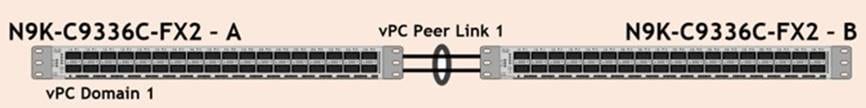
In the Cisco Nexus Switch topology, a single vPC feature is enabled to provide HA, faster convergence in the event of a failure, and greater throughput. Cisco Nexus vPC configurations with the vPC domains and corresponding vPC names and IDs for Oracle Database Servers is listed in Table 8.
| vPC Domain |
vPC Name |
vPC ID |
| 1 |
Peer-Link |
1 |
| 1 |
vPC FI-A |
41 |
| 1 |
vPC FI-B |
42 |
As listed in Table 7, a single vPC domain with Domain ID 1 is created across two Cisco Nexus switches to define vPC members to carry specific VLAN network traffic. In this topology, we defined a total number of 3 vPCs.
vPC ID 1 is defined as Peer link communication between the two Cisco Nexus switches. vPC IDs 41 and 42 are configured for both Cisco UCS fabric interconnects. Please follow these steps to create this configuration.
| Tech tip |
| A port channel bundles up to eight individual interfaces into a group to provide increased bandwidth and redundancy. |
Procedure 1. Create vPC Peer-Link
Note: For vPC 1 as Peer-link, we used interfaces 1 and 2 for Peer-Link. You may choose an appropriate number of ports based on your needs.
Step 1. Login as admin user into the Cisco Nexus Switch A:
configure terminal
vpc domain 1
peer-keepalive destination 10.29.135.154 source 10.29.135.153
auto-recovery
interface port-channel1
description vPC peer-link
switchport mode trunk
switchport trunk allowed vlan 1-2,10-11,134-135
spanning-tree port type network
vpc peer-link
interface Ethernet1/1
description Peer link 100g connected to N9K-B-Eth1/1
switchport mode trunk
switchport trunk allowed vlan 1-2,10-11,134-135
channel-group 1 mode active
interface Ethernet1/2
description Peer link 100g connected to N9K-B-Eth1/2
switchport mode trunk
switchport trunk allowed vlan 1-2,10-11,134-135
channel-group 1 mode active
copy run start
Step 2. Login as admin user into the Cisco Nexus Switch B and configure the second Cisco Nexus switch as follows:
| Tech tip |
| Make sure to change the description of interfaces and peer-keepalive destination and source IP addresses. |
configure terminal
vpc domain 1
peer-keepalive destination 10.29.135.153 source 10.29.135.154
auto-recovery
interface port-channel1
description vPC peer-link
switchport mode trunk
switchport trunk allowed vlan 1-2,10-11,134-135
spanning-tree port type network
vpc peer-link
interface Ethernet1/1
description Peer link 100g connected to N9K-A-Eth1/1
switchport mode trunk
switchport trunk allowed vlan 1-2,10-11,134-135
channel-group 1 mode active
interface Ethernet1/2
description Peer link 100g connected to N9K-A-Eth1/2
switchport mode trunk
switchport trunk allowed vlan 1-2,10-11,134-135
channel-group 1 mode active
copy run start
Create vPC Configuration between the Cisco Nexus Switches and Fabric Interconnects
This section describes how to create and configure port channel 41 and 42 for network traffic between the Cisco Nexus and Fabric Interconnect Switches.
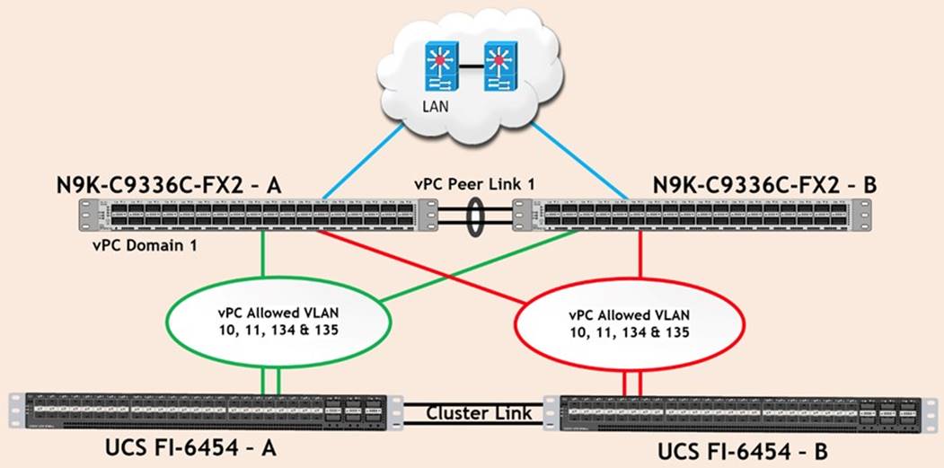
Table 9 lists the vPC IDs, allowed VLAN IDs, and Ethernet uplink ports.
| vPC Description |
vPC ID |
Fabric Interconnects Ports |
Cisco Nexus Switch Ports |
Allowed VLANs |
| Port Channel FI-A |
41 |
FI-A Port 1/49 |
N9K-A Port 1/25 |
10,11,134,135 |
| FI-A Port 1/50 |
N9K-B Port 1/25 |
|||
| Port Channel FI-B |
42 |
FI-B Port 1/49 |
N9K-A Port 1/26 |
10,11,134,135 |
| FI-B Port 1/50 |
N9K-B Port 1/26 |
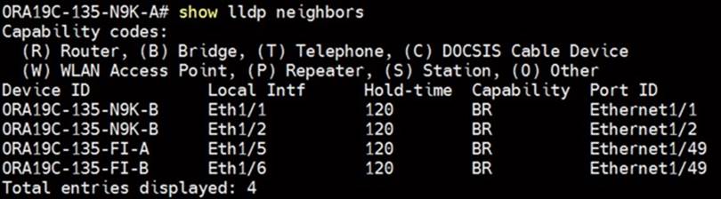
Verify the ports connectivity on both Cisco Nexus switches as shown below:

Procedure 1. Configure Port Channels on Cisco Nexus Switches
Step 1. Login as admin user into the Cisco Nexus Switch A:
configure terminal
interface port-channel41
description Port-Channel FI-A
switchport mode trunk
switchport trunk allowed vlan 1-2,10-11,134-135
spanning-tree port type edge trunk
mtu 9216
vpc 41
no shutdown
interface port-channel42
description Port-Channel FI-B
switchport mode trunk
switchport trunk allowed vlan 1-2,10-11,134-135
spanning-tree port type edge trunk
mtu 9216
vpc 42
no shutdown
interface Ethernet1/5
description 100g link to FI-A Port 49
switchport mode trunk
switchport trunk allowed vlan 1-2,10-11,134-135
spanning-tree port type edge trunk
mtu 9216
channel-group 41 mode active
no shutdown
interface Ethernet1/6
description 100g link to FI-B Port 49
switchport mode trunk
switchport trunk allowed vlan 1-2,10-11,134-135
spanning-tree port type edge trunk
mtu 9216
channel-group 42 mode active
no shutdown
copy run start
Step 2. Login as admin user into the Cisco Nexus Switch B and run the following commands to configure the second Cisco Nexus switch:
configure terminal
interface port-channel41
description Port-Channel FI-A
switchport mode trunk
switchport trunk allowed vlan 1-2,10-11,134-135
spanning-tree port type edge trunk
mtu 9216
vpc 41
no shutdown
interface port-channel42
description Port-Channel FI-B
switchport mode trunk
switchport trunk allowed vlan 1-2,10-11,134-135
spanning-tree port type edge trunk
mtu 9216
vpc 42
no shutdown
interface Ethernet1/5
description 100g link to FI-A Port 50
switchport mode trunk
switchport trunk allowed vlan 1-2,10-11,134-135
spanning-tree port type edge trunk
mtu 9216
channel-group 41 mode active
no shutdown
interface Ethernet1/6
description 100g link to FI-B Port 50
switchport mode trunk
switchport trunk allowed vlan 1-2,10-11,134-135
spanning-tree port type edge trunk
mtu 9216
channel-group 42 mode active
no shutdown
copy run start
Procedure 2. Verify all vPC status
Step 1. Run this command for the Cisco Nexus Switch A Port-Channel Summary:
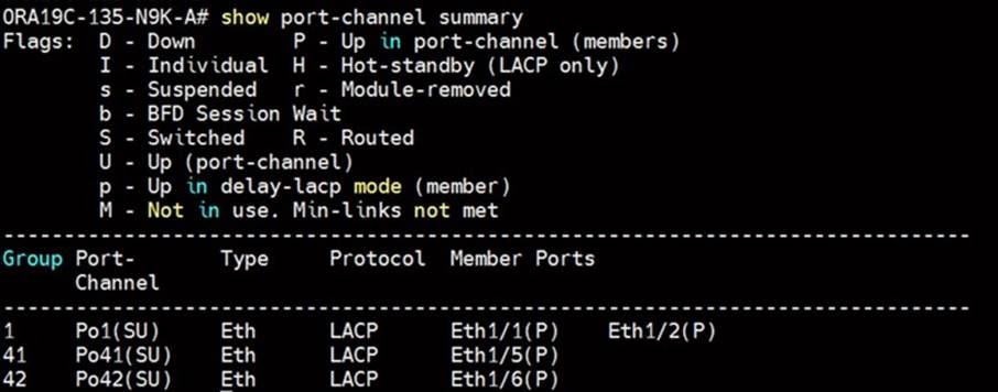
Step 2. Run this command for the Cisco Nexus Switch B Port-Channel Summary:

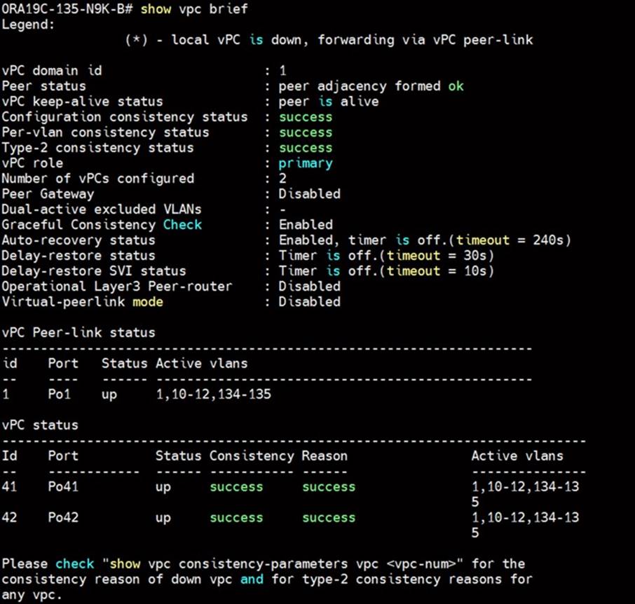
Step 3. Run this command for the Cisco Nexus Switch A vPC Status:

Step 4. Run this command for the Cisco Nexus Switch B vPC Status:
This section details the Cisco UCS configuration that was completed as part of the infrastructure buildout. The racking, power, and installation of the chassis are described in the installation guide, see: https://www.cisco.com/c/en/us/support/servers-unified-computing/ucs-manager/products-installation-guides-list.html
Note: It is beyond the scope of this document to explain the Cisco UCS infrastructure setup and connectivity. The documentation guides and examples are available here: https://www.cisco.com/c/en/us/support/servers-unified-computing/ucs-manager/products-installation-and-configuration-guides-list.html.
Note: This document details all the tasks to configure Cisco UCS but only some screenshots are included.
Using logical servers that are disassociated from the physical hardware removes many limiting constraints around how servers are provisioned. Cisco UCS Service Profiles contain values for a server's property settings, including virtual network interface cards (vNICs), MAC addresses, boot policies, firmware policies, fabric connectivity, external management, and HA information. The service profiles represent all the attributes of a logical server in Cisco UCS model. By abstracting these settings from the physical server into a Cisco Service Profile, the Service Profile can then be deployed to any physical compute hardware within the Cisco UCS domain. Furthermore, Service Profiles can, at any time, be migrated from one physical server to another. Furthermore, Cisco is the only hardware provider to offer a truly unified management platform, with Cisco UCS Service Profiles and hardware abstraction capabilities extending to both blade and rack servers.
High-Level Steps to Configure Base Cisco UCS
The following are the high-level steps involved for a Cisco UCS configuration:
1. Perform Initial Setup of Fabric Interconnects for a Cluster Setup
2. Upgrade UCS Manager Software to Version 4.2(1i)
3. Synchronize Cisco UCS to NTP
4. Configure Fabric Interconnects for Chassis and Blade Discovery
5. Configure Global Policies
6. Configure Server Ports
7. Configure LAN and SAN
8. Configure Ethernet LAN Uplink Ports
9. Create Uplink Port Channels to Nexus Switches
10. Configure FC SAN Uplink Ports
11. Configure VLANs
12. Configure VSANs
13. Create FC Uplink Port Channels to MDS Switches
14. Enable FC Uplink VSAN Trunking (FCP)
15. Configure IP, UUID, Server, MAC, WWNN and WWPN Pools
16. IP Pool Creation
17. UUID Suffix Pool Creation
18. Server Pool Creation
19. MAC Pool Creation
20. WWNN and WWPN Pool
21. Set Jumbo Frames in both the Fabric Interconnect
22. Configure Server BIOS Policy
23. Create Adapter Policy
24. Create Adapter Policy for Public and Private Network Interfaces
25. Create Adapter Policy for NVMe FC Storage Network Interfaces
26. Configure Update Default Maintenance Policy
27. Configure Host Firmware Policy
28. Configure vNIC and vHBA Template
29. Create Public vNIC Template
30. Create Private vNIC Template
31. Create Storage FC Storage vHBA Template
32. Create Server Boot Policy for SAN Boot
The details for each of these steps are documented in the following sections.
Perform Initial Setup of Cisco UCS 6454 Fabric Interconnects for a Cluster Setup
This section provides detailed procedures for configuring the Cisco Unified Computing System (Cisco UCS) for use in a FlashStack environment.
| Tech tip |
| The steps are necessary to provision the Cisco UCS B-Series and C-Series servers and should be followed precisely to avoid improper configuration. |
Procedure 1. Configure FI-A and FI-B
Step 1. Verify the following physical connections on the fabric interconnect:
The management Ethernet port (mgmt0) is connected to an external hub, switch, or router
The L1 ports on both fabric interconnects are directly connected to each other
The L2 ports on both fabric interconnects are directly connected to each other
Step 2. Connect to the console port on the first Fabric Interconnect and run the following:
Enter the configuration method. (console/gui) ? console
Enter the setup mode; setup newly or restore from backup. (setup/restore) ? setup
You have chosen to setup a new Fabric interconnect. Continue? (y/n): y
Enforce strong password? (y/n) [y]: Enter
Enter the password for "admin": <password>
Confirm the password for "admin": <password>
Is this Fabric interconnect part of a cluster(select 'no' for standalone)? (yes/no) [n]: y
Enter the switch fabric (A/B) []: A
Enter the system name: <ucs-cluster-name>
Physical Switch Mgmt0 IP address : <ucsa-mgmt-ip>
Physical Switch Mgmt0 IPv4 netmask : <ucsa-mgmt-mask>
IPv4 address of the default gateway : <ucsa-mgmt-gateway>
Cluster IPv4 address : <ucs-cluster-ip>
Configure the DNS Server IP address? (yes/no) [n]: y
DNS IP address : <dns-server-1-ip>
Configure the default domain name? (yes/no) [n]: y
Default domain name : <ad-dns-domain-name>
Join centralized management environment (UCS Central)? (yes/no) [n]: Enter
Apply and save the configuration (select 'no' if you want to re-enter)? (yes/no): yes
Step 3. Review the settings printed to the console. Answer yes to apply and save the configuration.
Step 4. Wait for the login prompt to make the configuration has been saved to Fabric Interconnect A.
Step 5. Connect console port on the second Fabric Interconnect B and run the following:
Enter the configuration method. (console/gui) ? console
Installer has detected the presence of a peer Fabric interconnect. This Fabric interconnect will be added to the cluster. Continue (y/n) ? y
Enter the admin password of the peer Fabric interconnect: <password>
Connecting to peer Fabric interconnect... done
Retrieving config from peer Fabric interconnect... done
Peer Fabric interconnect Mgmt0 IPv4 Address: <ucsa-mgmt-ip>
Peer Fabric interconnect Mgmt0 IPv4 Netmask: <ucsa-mgmt-mask>
Cluster IPv4 address : <ucs-cluster-ip>
Peer FI is IPv4 Cluster enabled. Please Provide Local Fabric Interconnect Mgmt0 IPv4 Address
Physical Switch Mgmt0 IP address : <ucsb-mgmt-ip>
Local fabric interconnect model(UCS-FI-6454)
Peer fabric interconnect is compatible with the local fabric interconnect. Continuing with the installer...
Apply and save the configuration (select 'no' if you want to re-enter)? (yes/no): yes
Step 6. Review the settings printed to the console. Answer yes to apply and save the configuration.
Step 7. Wait for the login prompt to make the configuration has been saved to Fabric Interconnect B.
Procedure 2. Log into Cisco UCS Manager
Step 1. Log into Cisco Unified Computing System (Cisco UCS) environment.
Step 2. Open a web browser and navigate to the Cisco UCS fabric interconnect cluster address.
Step 3. Click the Launch UCS Manager link under HTML to launch Cisco UCS Manager.
Step 4. If prompted to accept security certificates, accept as necessary.
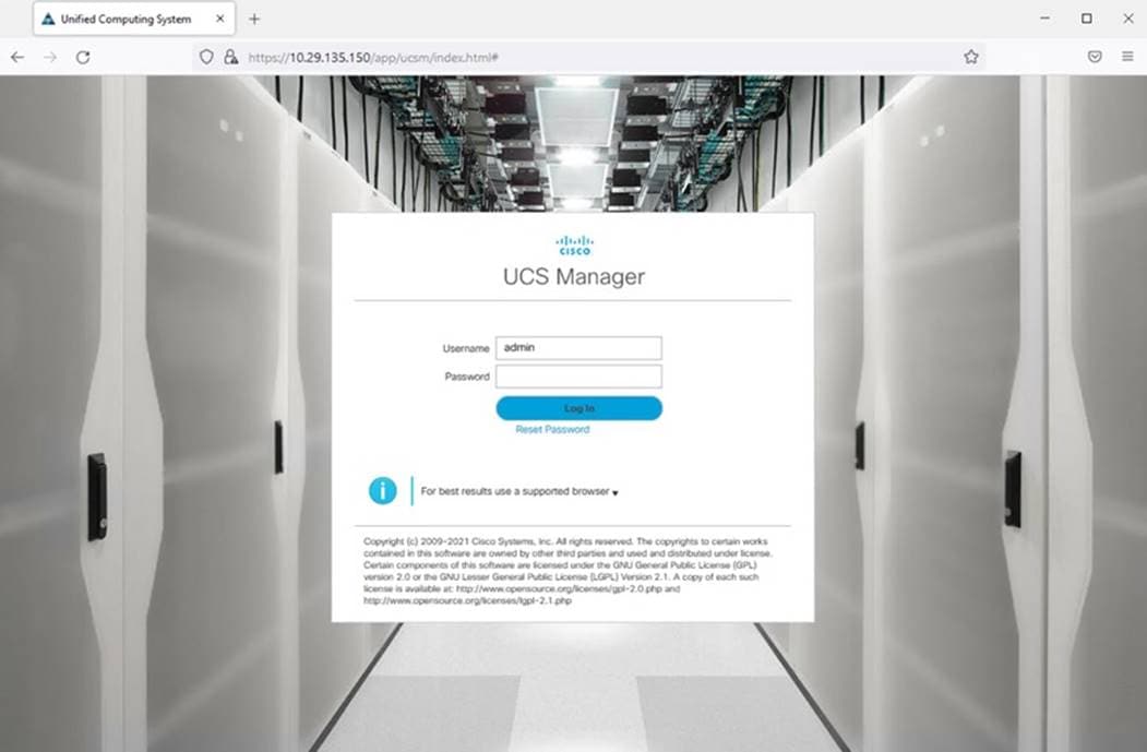
Step 5. When prompted, enter admin as the username and enter the administrative password.
Step 6. Click Login to log into Cisco UCS Manager.
Procedure 3. Configure Cisco UCS Call Home
| Tech tip |
| It is highly recommended by Cisco to configure Call Home in Cisco UCS Manager. Configuring Call Home will accelerate resolution of support cases. |
Step 1. In Cisco UCS Manager, click Admin.
Step 2. Select All > Communication Management > Call Home.
Step 3. Change the State to On.
Step 4. Fill in all the fields according to your Management preferences and click Save Changes and OK to complete configuring Call Home.
Upgrade Cisco UCS Manager Software to Version 4.2 (1i)
This solution was configured on Cisco UCS 4.2(1i) software release. To upgrade the Cisco UCS Manager software and the Cisco UCS Fabric Interconnect software to version 4.2, go to: https://software.cisco.com/download/home/283612660/type/283655658/release/4.2(1i)
For more information about Install and Upgrade Guides, go to: https://www.cisco.com/c/en/us/support/servers-unified-computing/ucs-manager/products-installation-guides-list.html
Synchronize Cisco UCS to NTP Server
It’s important to synchronize Cisco UCS to the NTP server, because you want to make sure that logging information and timestamps have the accurate time and date.
Procedure 1. Synchronize Cisco UCS to NTP
Step 1. In Cisco UCS Manager, in the navigation pane, click the Admin tab.
Step 2. Select All > Time zone Management.
Step 3. In the Properties pane, select the appropriate time zone in the Time zone menu.
Step 4. Click Save Changes and then click OK.
Step 5. Click Add NTP Server.
Step 6. Enter the NTP server IP address and click OK.
Step 7. Click OK to finish.
Configure Fabric Interconnect for Chassis and Server Discovery
Cisco UCS 6454 Fabric Interconnects are configured for redundancy. It provides resiliency in case of failures. The first step to establish connectivity between blades and Fabric Interconnects.
Procedure 1. Configure Global Policies
| Tech tip |
| The chassis discovery policy determines how the system reacts when you add a new chassis. We recommend using the platform max value as shown. Using platform max helps ensure that Cisco UCS Manager uses the maximum number of IOM uplinks available. |
Step 1. Go to Equipment > Policies > Global Policies > Chassis/FEX Discovery Policies. As shown in the screenshot below, select Action as Platform Max from the drop-down list and set Link Grouping to Port Channel.
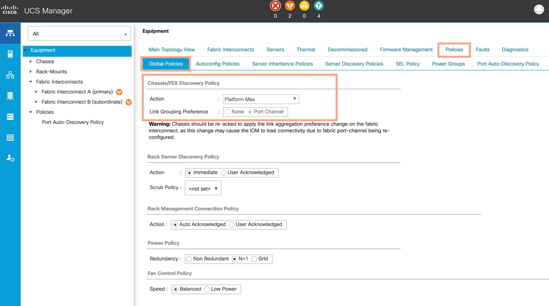
Step 2. Click Save Changes.
Step 3. Click OK.
Procedure 2. Configure Server Ports
You need to configure Server Ports to initiate the chassis and blade discovery.
Step 1. Go to Equipment > Fabric Interconnects > Fabric Interconnect A > Fixed Module > Ethernet Ports.
Step 2. Select the ports (for this solution ports are 17-32) which are connected to the Cisco IO Modules of the two Cisco UCS B-Series 5108 Chassis.
Step 3. Right-click and select Configure as Server Port.
Step 4. Click Yes to confirm and click OK.
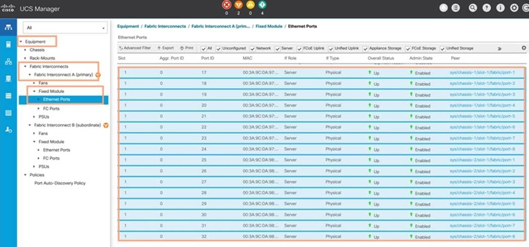
Step 5. Repeat steps 1-4 for Fabric Interconnect B.
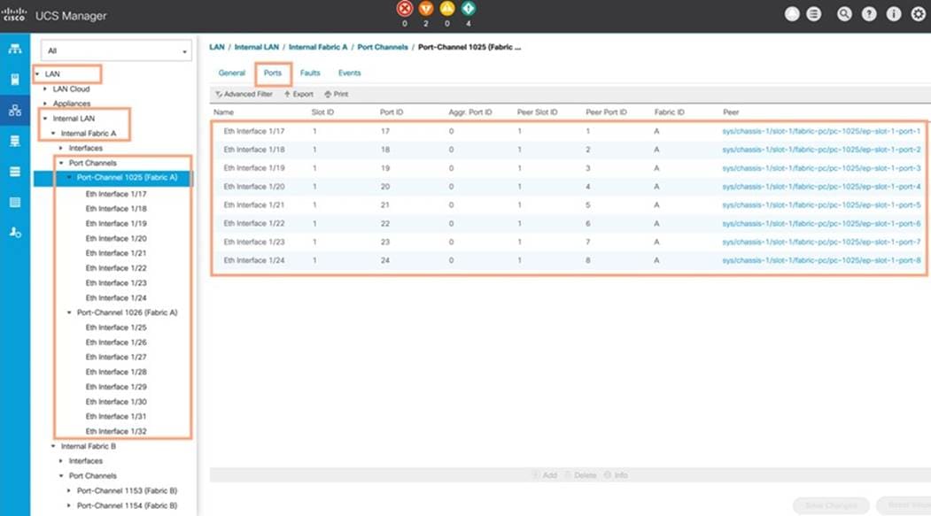
Step 6. After configuring Server Ports, acknowledge both Chassis. Go to Equipment > Chassis > Chassis 1 > General > Actions > select Acknowledge Chassis. Repeat this step to acknowledge the Chassis 2.
Step 7. After acknowledging both chassis, re-acknowledge all servers placed in the chassis. Go to Equipment > Chassis 1 > Servers > Server 1 > General > Actions > select Server Maintenance > select option Re-acknowledge and click OK. Repeat this step to re-acknowledge all eight Servers.
Step 8. When the acknowledgement of the Servers is completed, verify the Port-channel of Internal LAN on both chassis as shown below. Go to tab LAN > Internal LAN > Internal Fabric A > Port Channels on both chassis as shown below.
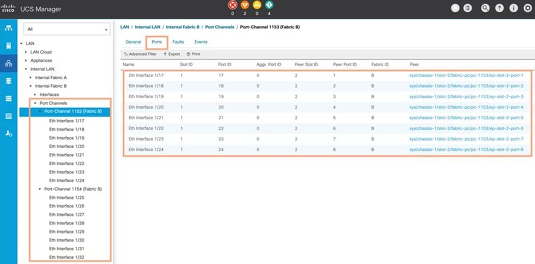
Step 9. Verify the same for Internal Fabric B.
Configure LAN and SAN on Cisco UCS Manager
Configure Ethernet Uplink Ports and Fibre Channel (FC) Storage ports on Cisco UCS Manager as explained below.
Procedure 1. Configure Ethernet LAN Uplink Ports
Step 1. In Cisco UCS Manager, in the navigation pane, click the Equipment tab.
Step 2. Select Equipment > Fabric Interconnects > Fabric Interconnect A > Fixed Module.
Step 3. Expand Ethernet Ports.
Step 4. Select ports (for this solution ports are 49-50) that are connected to the Cisco Nexus switches, right-click them, and select Configure as Network Port.
Step 5. Click Yes to confirm ports and click OK.
Step 6. Verify the Ports connected to Nexus upstream switches are now configured as network ports.
Step 7. Repeat steps 1-6 for Fabric Interconnect B. The screenshot shows the network uplink ports for Fabric A.
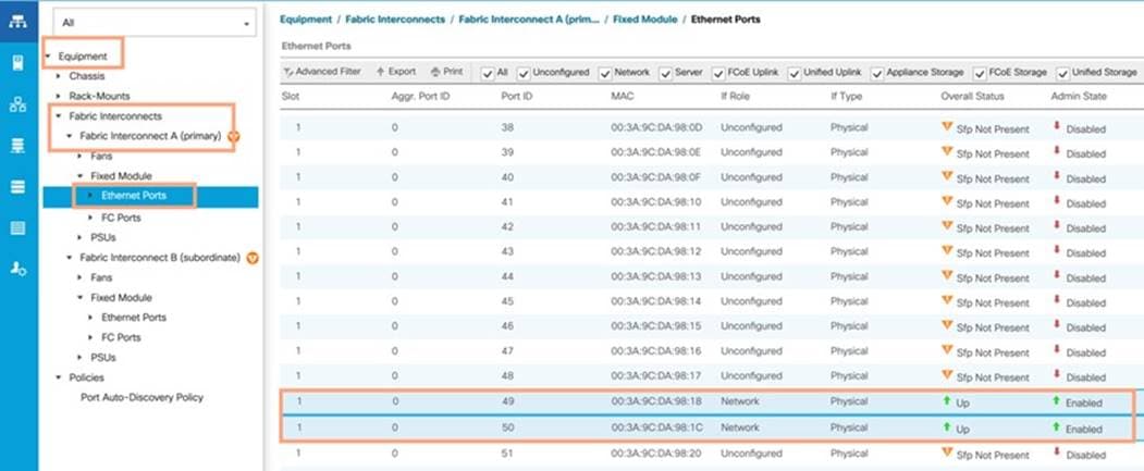
Now two uplink ports have been created on each Fabric Interconnect as shown above. These ports will be used to create Virtual Port Channel in the next section.
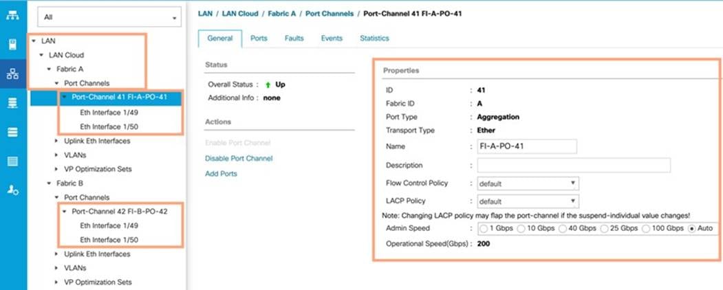
Procedure 2. Create Uplink Port Channels to Cisco Nexus Switches
| Tech tip |
| In this procedure, two port channels are created: one from Fabric A to both Cisco Nexus switches and one from Fabric B to both Cisco Nexus switches. |
Step 1. In Cisco UCS Manager, click the LAN tab in the navigation pane.
Step 2. Under LAN > LAN Cloud, expand node Fabric A tree.
Step 3. Right-click Port Channels.
Step 4. Select Create Port Channel.
Step 5. Enter 41 as the unique ID of the port channel.
Step 6. Enter FI-A-PO-41 as the name of the port channel.
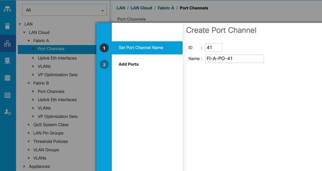
Step 7. Click Next.
Step 8. Select Ethernet ports 49-50 for the port channel.
Step 9. Click >> to add the ports to the port channel
Step 10. Click Finish to create the port channel and then click OK.
Step 11. Repeat steps 1-10 for Fabric Interconnect B, substituting 52 for the port channel number and FI-B for the name.
Procedure 3. Configure FC SAN Uplink Ports for Fabric Interconnect 6454
Step 1. In Cisco UCS Manager, click Equipment.
Step 2. Select Equipment > Fabric Interconnects > Fabric Interconnect A (primary).
Step 3. Select Configure Unified Ports.
Step 4. Click Yes on the pop-up window warning that changes to the fixed module will require a reboot of the fabric interconnect and changes to the expansion module will require a reboot of that module.
Step 5. Within the Configured Fixed Ports pop-up window move the gray slider bar from the left to the right to select either 4, 8, or 12 ports to be set as FC Uplinks.
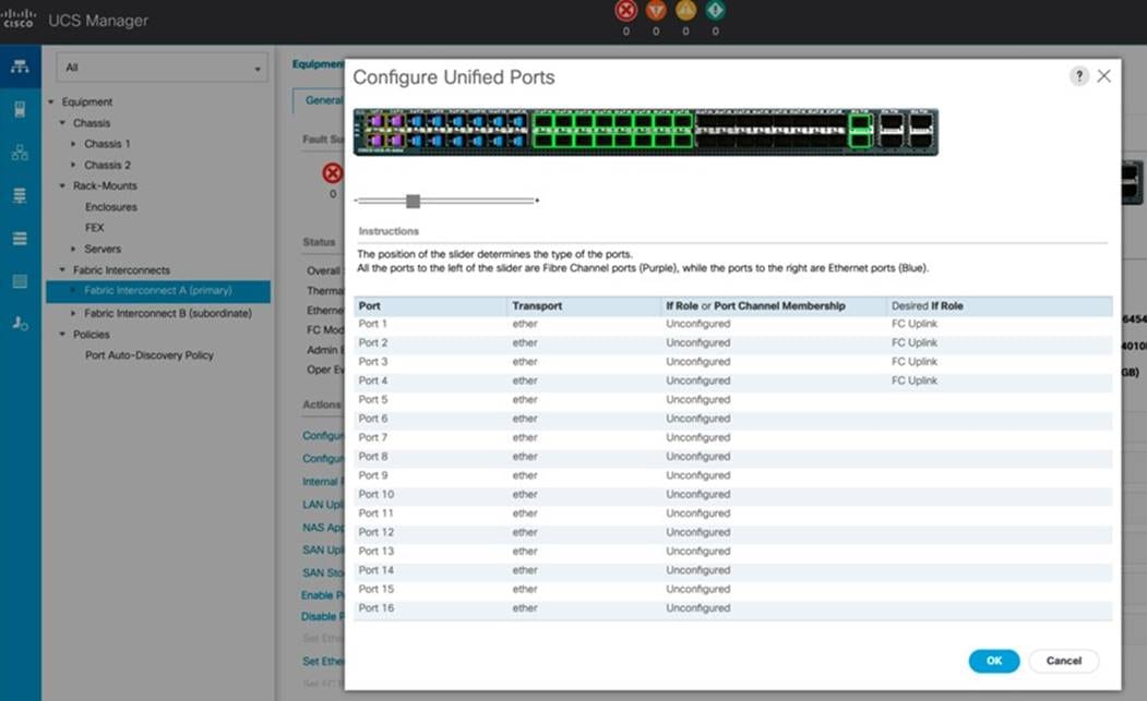
Note: For this solution, we configured the first four ports on the FI as FC Uplink ports.
Step 6. Click OK, then click Yes, then click OK to continue.
Note: Applying this configuration will cause the immediate reboot of Fabric Interconnect and/or Expansion Module(s).
Step 7. Click Equipment > Fabric Interconnects > Fabric Interconnect B (primary).
Step 8. Click Configure Unified Ports.
Step 9. Click Yes on the pop-up window warning that changes to the fixed module will require a reboot of the fabric interconnect and changes to the expansion module will require a reboot of that module.
Step 10. Within the Configured Fixed Ports pop-up window move the gray slider bar from the left to the right to select either 4, 8, or 12 ports to be set as FC Uplinks.
Step 11. Click OK then click Yes then click OK to continue.
Step 12. Wait for both Fabric Interconnects to reboot.
Step 13. Log back into Cisco UCS Manager.
Procedure 4. Configure VLAN
Note: In this solution, five VLANs were created as listed in Table 5: VLAN 2 for Native VLAN, VLAN 134 for ESXi Management Network, VLAN 135 for VM Management Network, VLAN 10 for Private Server-to-Server Network (Cache Fusion) Traffic for Oracle RAC and VLAN 11 for vMotion and Database Backup Network Traffic. These VLANs will be used in the vNIC templates that are discussed later.
| Tech tip |
| It is very important to create both VLANs as global across both fabric interconnects. This way, the VLAN identity is maintained across the fabric interconnects in case of a NIC failover. |
Step 1. In Cisco UCS Manager, click the LAN tab in the navigation pane.
Step 2. Click LAN > LAN Cloud.
Step 3. Right-click VLANs.
Step 4. Click Create VLANs.
Step 5. Enter ESX_Public_Network as the name of the VLAN to be used for ESXi Management Network Traffic.
Step 6. Keep the Common/Global option selected for the scope of the VLAN.
Step 7. Enter 134 as the ID of the VLAN ID.
Step 8. Keep the Sharing Type as None.
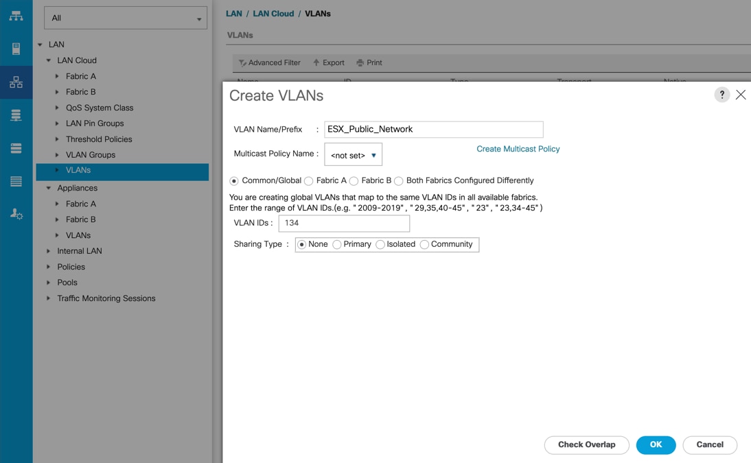
Step 9. Click OK and then click OK again.
Step 10. Create the remaining VLANs for VM Management Network, Private Server-to-Server Network (Interconnect), vMotion and Native VLAN as shown below:
Note: These VLANs will be used in the vNIC templates that are described in this CVD.
Procedure 5. Configure VSAN
Note: In this solution, we created two VSANs. VSAN-A 151 and VSAN-B 152 for FC SAN Storage Access.
Step 1. In Cisco UCS Manager, click the SAN tab in the navigation pane.
Step 2. Select SAN > SAN Cloud > Fabric A > VSANs
Step 3. Under VSANs, right-click on VSANs.
Step 4. Select Create VSAN.
Step 5. Enter VSAN-A as the name of the VSAN.
Step 6. Leave FC Zoning set at Disabled.
Step 7. Select Fabric A for the scope of the VSAN.
Step 8. Enter VSAN ID as 151.
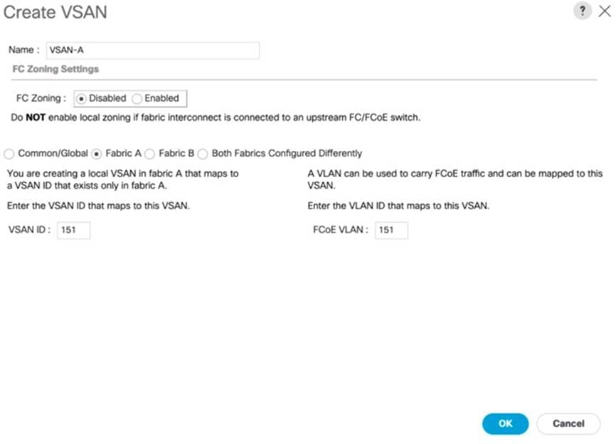
Step 9. Click OK and then click OK again
Step 10. Repeat steps 1-9 to create the VSAN 152 on FI-B.
| Tech tip |
| Enter a unique VSAN ID and a corresponding FCoE VLAN ID that matches the configuration in the MDS switch for Fabric A. It is recommended to use the same ID for both parameters and to use something other than 1. |
Procedure 6. Create FC Uplink Port Channels to MDS Switches
Note: In this solution, we created two FC Port Chanel. The first FC Port Channel is between FI-A to MDS-A and the second FC Port Channel is between FI-B to MDS-B.
Step 1. In Cisco UCS Manager, click SAN tab on the left.
Step 2. Click SAN > SAN Cloud > Fabric A > FC Port Channels > and then right-click on the FC Port Channel.
Step 3. Enter the name of Port Channel as FC-PC-A and unique ID as 251and click Next
Step 4. Select the appropriate ports of FI-A which are going to MDS-A and click the button >> to select those ports as a member of the Port Channel.
Note: For this solution, we configured all four ports as Port Channel ports as shown in the screenshot below:
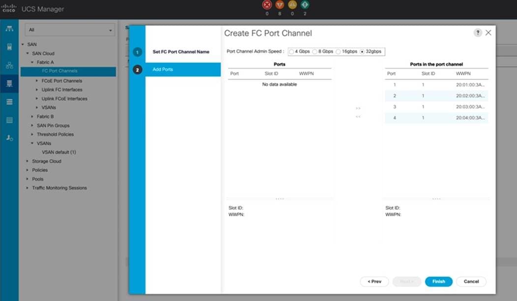
Step 5. Click Finish to create this FC Port Channel for FI-A.
Step 6. Repeat steps 1-5 to create the FC Port Channel on FI-B with related FC Ports going to MDS-B.
Note: We configured the FI-B Port Channel as FC-PC-B with unique ID 252 as shown below:
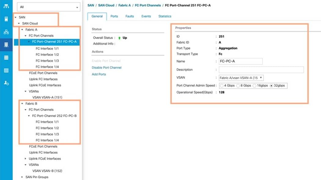
Step 7. Click VSAN-A 151 for FC-PC-A and click Save Changes.
Step 8. Click VSAN-B 152 for FC-PC-B and click Save Changes.
Note: The MDS Switch is configured in the following section and after the appropriate VSAN and FC ports configuration, the FC Ports and Port-Channel will become ACTIVE.
Procedure 7. Enable FC Uplink VSAN Trunking (FCP)
Step 1. In Cisco UCS Manager, click SAN.
Step 2. Expand SAN > SAN Cloud.
Step 3. Choose Fabric A and in the Actions pane choose Enable FC Uplink Trunking.
Step 4. Click Yes on the Confirmation and Warning and then click OK.
Step 5. Choose Fabric B and in the Actions pane choose Enable FC Uplink Trunking.
Step 6. Click Yes on the Confirmation and Warning. Click OK to finish.
| Tech tip |
| Enabling VSAN trunking is optional. It is important that the Cisco Nexus VSAN trunking configuration match the configuration set in Cisco UCS Manager. |
Configure IP, UUID, Server, MAC, WWNN and WWPN Pools
Procedure 1. IP Pool Creation
| Tech tip |
| An IP address pool on the out-of-band management network must be created to facilitate KVM access to each compute node in the UCS domain. |
Step 1. In Cisco UCS Manager, in the navigation pane, click the LAN tab.
Step 2. Click Pools > root > IP Pools >click Create IP Pool.
Note: For this solution, the IP Pool is named ORA19C-KVM Pool.
Step 3. Select the option Sequential to assign IP in sequential order then click Next.
Step 4. Click Add IPv4 Block.
Step 5. Enter the starting IP address of the block and the number of IP addresses required and the subnet and gateway information according to your environment, as shown below:
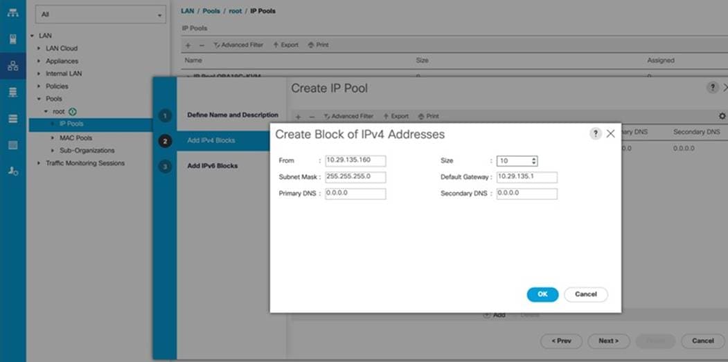
Step 6. Click Next and then click Finish to create the IP block.
Procedure 2. UUID Suffix Pool Creation
Step 1. In Cisco UCS Manager, click the Servers tab in the navigation pane.
Step 2. Click Pools > root.
Step 3. Right-click UUID Suffix Pools and then select Create UUID Suffix Pool.
Step 4. Enter ORA19C-UUID as the name of the UUID Pool name.
Step 5. Optional: Enter a description for the UUID pool.
Step 6. Keep the prefix at the derived option and select Sequential in as Assignment Order then click Next.
Step 7. Click Add to add a block of UUIDs.
Step 8. Create a starting point UUID as per your environment.
Step 9. Specify a size for the UUID block that is sufficient to support the available blade or server resources.
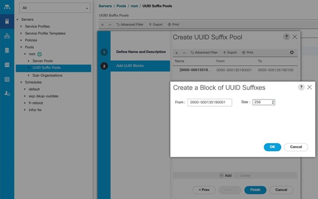
Step 10. Clink OK then click Finish to complete the UUID Pool configuration.
Procedure 3. Server Pool Creation
| Tech tip |
| Consider creating unique server pools to achieve the granularity that is required in your environment. |
Step 1. In Cisco UCS Manager, click the Servers tab in the navigation pane.
Step 2. Select Pools > root > Right-click Server Pools > Select Create Server Pool.
Step 3. Enter ORA19C-SERVER-POOL as the name of the server pool.
Step 4. Optional: Enter a description for the server pool then click Next.
Step 5. Select all the eight servers to be used for the Oracle RAC management and click >> to add them to the server pool.
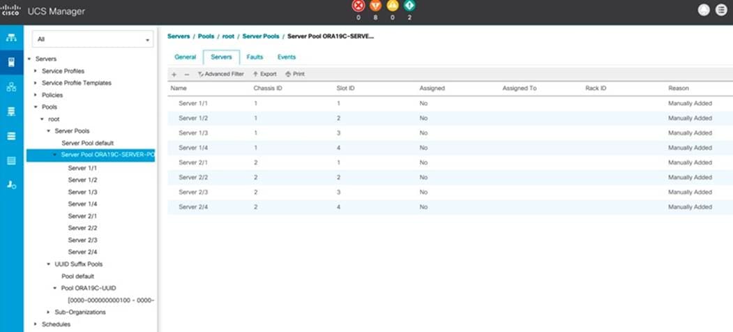
Step 6. Click Finish and then click OK.
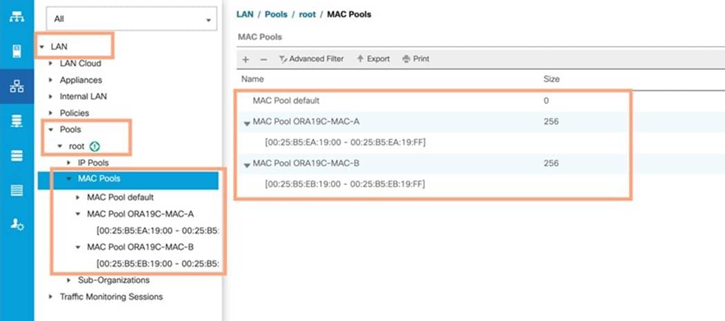
Procedure 4. MAC Pool Creation
Note: In this solution, we created two MAC Pool as ORA19C-MAC-A and ORA19C-MAC-B to provide MAC addresses for all of the Network Interfaces.
Step 1. In Cisco UCS Manager, click the LAN tab in the navigation pane.
Step 2. Select Pools > root > right-click MAC Pools under the root organization.
Step 3. Select Create MAC Pool to create the MAC address pool.
Step 4. Enter ORA19C-MAC-A as the name for MAC pool.
Step 5. Enter the seed MAC address and provide the number of MAC addresses to be provisioned.
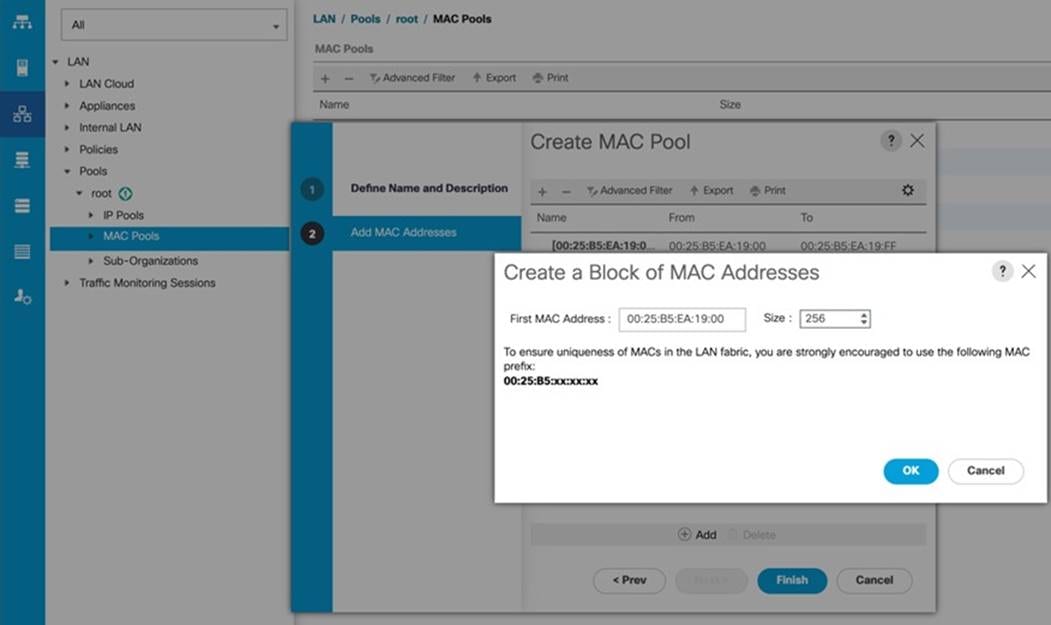
Step 6. Click OK and then click Finish.
Step 7. In the confirmation message, click OK.
Step 8. Create MAC Pool B as “ORA19C-MAC-B” and assign unique MAC Addresses as shown below:
Procedure 5. Create a WWNN Pool
Note: In this solution, we configured one WWNN Pool to provide SAN access point for ESX and Linux VM hosts.
| Tech tip |
| These WWNN and WWPN entries will be used to access storage through SAN configuration. |
Step 1. In Cisco UCS Manager, click the SAN tab in the navigation pane.
Step 2. Click Pools > Root > WWNN Pools > right-click WWNN Pools > click Create WWNN Pool.
Step 3. Assign the name ORA19C-WWNN and Assignment Order as sequential and click Next.
Step 4. Click Add and create a WWN Block as shown below:
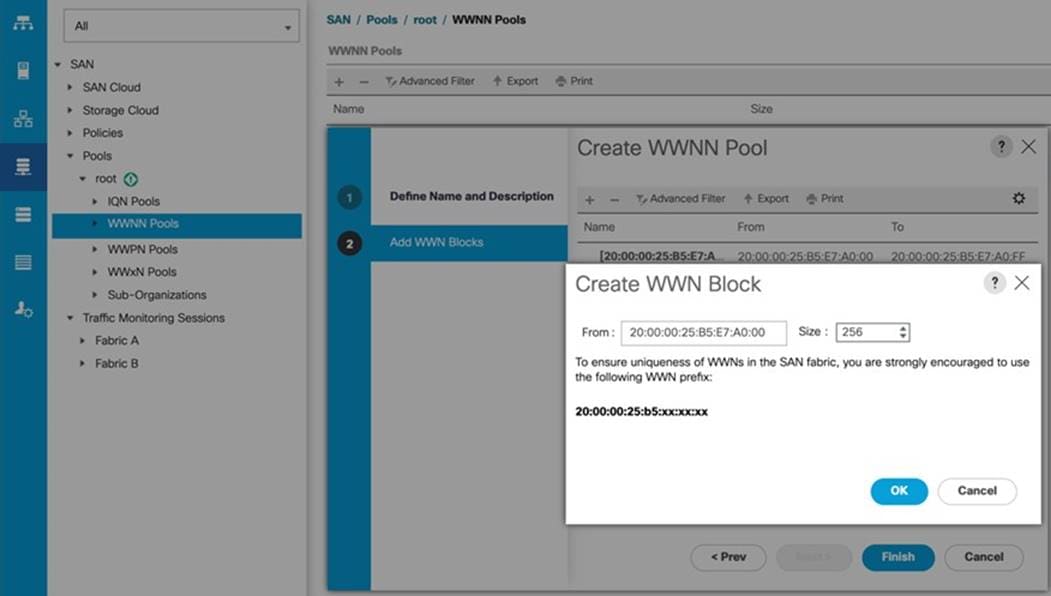
Step 5. Click OK and then click Finish.
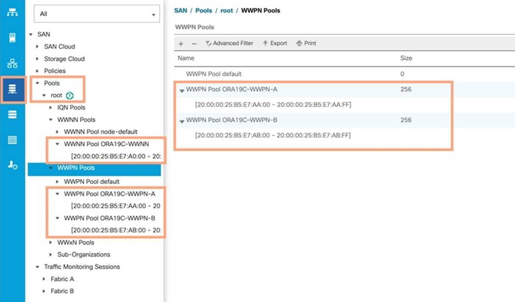
Procedure 6. Create WWPN Pools
Note: In this solution, we created two WWPNs; ORA19C-WWPN-A and ORA19C-WWPN-B Pool, for the World Wide Port Name.
Step 1. In Cisco UCS Manager, click the SAN tab in the navigation pane.
Step 2. Click Pools > Root > WWPN Pools > right-click WWPN Pools > click Create WWPN Pool.
Step 3. Assign the name ORA19C-WWPN-A and Assignment Order as sequential.
Step 4. Click Next and then click Add to add block of Ports.
Step 5. Enter Block for WWN and size.
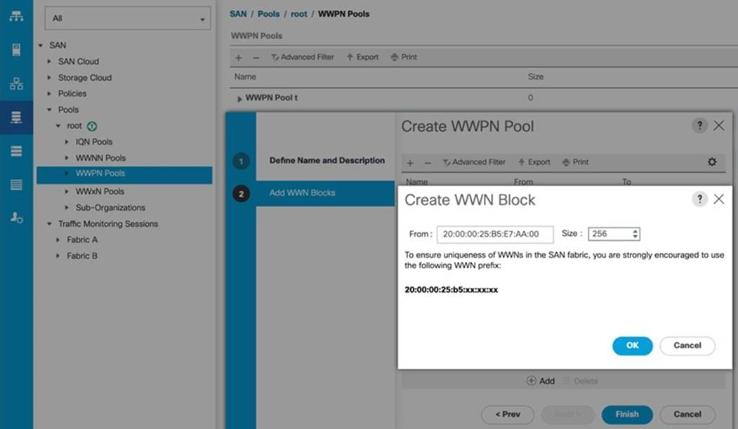
Step 6. Click OK and then click Finish.
Step 7. Configure the ORA19C-WWPN-B Pool as well and assign the unique block IDs as shown below:
| Tech tip |
| When there are multiple UCS domains sitting in adjacency, it is important that these blocks; the WWNN, WWPN, and MAC, hold differing values between each set. |
Set Jumbo Frames in both Cisco Fabric Interconnects
This section describe how to configure jumbo frames and enable quality of service in the Cisco UCS fabric.
Procedure 1. Set Jumbo Frames
Step 1. In Cisco UCS Manager, click the LAN tab in the navigation pane.
Step 2. Select LAN > LAN Cloud > QoS System Class.
Step 3. In the right pane, click the General tab.
Step 4. On the Best Effort row, enter 9216 in the box under the MTU column.
Step 5. Click Save Changes in the bottom of the window.
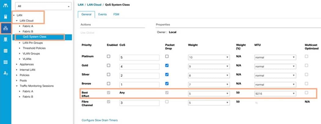
Step 6. Click OK.
Note: The only the Fibre Channel and Best Effort QoS System Classes are enabled in this FlashStack implementation. The Cisco UCS and Cisco Nexus switches are intentionally configured this way so that all IP traffic within the FlashStack will be treated as Best Effort.
| Tech tip |
| Enabling the other QoS System Classes without having a comprehensive, end-to-end QoS setup in place can cause difficult to troubleshoot issues. |
All the Server BIOS policies may be required for your setup. Please follow the steps according to your environment and requirements. The following changes were made on the test bed where Oracle RAC installed. Please validate and change as needed.
For more detailed information on BIOS Settings, go to https://www.cisco.com/c/en/us/products/collateral/servers-unified-computing/ucs-b-series-blade-servers/performance-tuning-guide-ucs-m6-servers.html
Procedure 1. Create a Server BIOS Policy for the Cisco UCS environment
Step 1. In Cisco UCS Manager, click Servers.
Step 2. Click Policies > root.
Step 3. Right-click BIOS Policies.
Step 4. Click Create BIOS Policy.
Step 5. Enter ORA-VM as the BIOS policy name
Step 6. Select and click the newly created BIOS Policy.
Step 7. Click the Main tab and select CDN Control value as Enabled.
Step 8. Click the Advanced tab, leaving the Processor tab selected within the Advanced tab.
Step 9. Set the following within the Processor tab:
● Enhanced CPU Performance: Disabled
● Intel HyperThreading Tech: Enabled
● Energy Efficient Turbo: Disabled
● IMC Inteleave: 1-way Interleave
● Sub NUMA Clustering: Enabled
● Processor C1E: Disabled
● LLC Prefetch: Disabled
● XPT Prefetch: Enabled
● Patrol Scrub: Disabled
● UPI Power Management: Enabled
Step 10. Set the following within the RAS Memory tab:
● LLC Dead Line: Disabled
● Memory Refresh Rate: 1x Refresh
Step 11. Click Save Changes and then click OK.
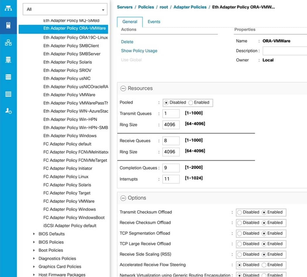
Note: In this solution, we used the default UCS “vmware” adapter policy for the ethernet NICs and fibre channel HBA. However, for the Oracle RAC interconnect NICs, we customized the ethernet adapter policy as explained below.
Procedure 1. Create Adapter Policy for Ethernet Traffic (only for Oracle RAC Private Network Interfaces)
Step 1. In Cisco UCS Manager, click the Servers tab in the navigation pane.
Step 2. Select Policies > root > right-click Adapter Policies.
Step 3. Select Create Ethernet Adapter Policy.
Step 4. Provide a name for the Ethernet adapter policy as “ORA-VMWare”. Change the following fields and click Save Changes:
● Resources:
◦ Transmit Queues: 1
◦ Ring Size: 4096
◦ Receive Queues: 8
◦ Ring Size: 4096
◦ Completion Queues: 9
◦ Interrupts: 11
● Options:
◦ Receive Side Scaling (RSS): Enabled
Step 5. Configure the adapter policy as shown below:
RSS distributes network receive processing across multiple CPUs in multiprocessor systems, as follows:
● Disabled—Network receive processing is always handled by a single processor even if additional processors are available.
● Enabled—Network receive processing is shared across processors whenever possible.
Configure Default Maintenance Policy
You’ll need to configure your default maintenance policy for your specific environment requirements.
Procedure 1. Configure Default Maintenance Policy
Step 1. In Cisco UCS Manager, click the Servers tab in the navigation pane.
Step 2. Click Policies > root > Maintenance Policies > Default.
Step 3. Change the Reboot Policy to User Ack.
Step 4. Click Save Changes.
Step 5. Click OK to accept the changes.
Configure Host Firmware Policy
Firmware management policies allow the administrator to choose the corresponding packages for a given server configuration. These policies often include packages for adapter, BIOS, board controller, FC adapters, host bus adapter (HBA) option ROM, and storage controller properties.
Procedure 1. Create Default Firmware Management Policy
Step 1. In Cisco UCS Manager, click Servers.
Step 2. Expand Policies > root.
Step 3. Expand Host Firmware Packages and right-click to “Create Host Firmware Policy.”
Step 4. Give the policy the name 4.2-1i and select the Blade and Rack Packages as shown below:
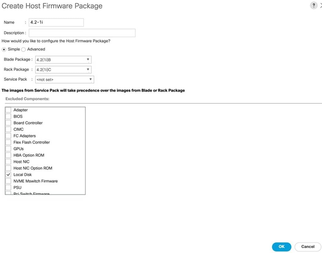
Step 5. Click OK, to create the host firmware package for this UCSM version.
Configure vNIC and vHBA Template
Note: For this solution, we created two vNIC template for Public Network and Private Network Traffic. We will use these vNIC templates when creating the Service Profile later in this section.
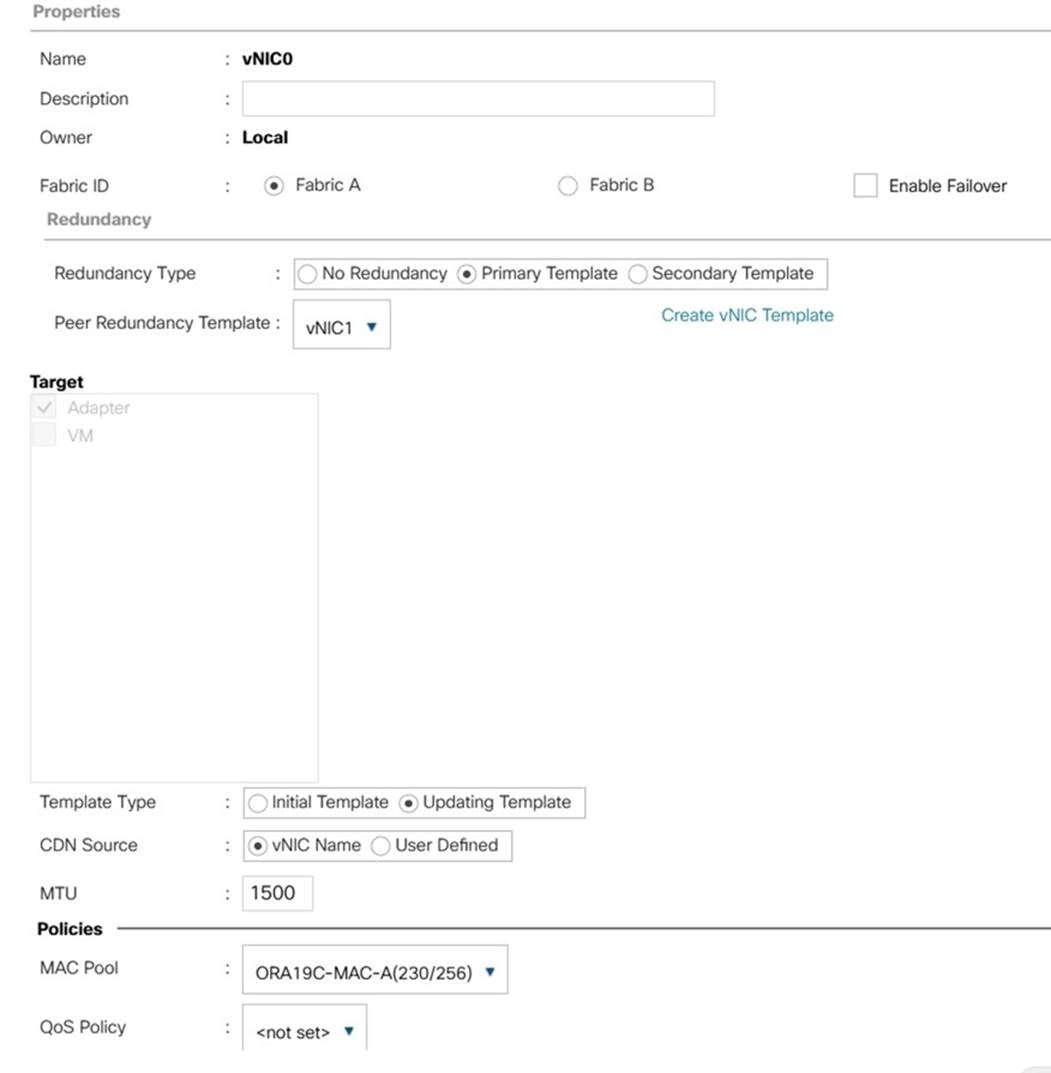
Procedure 1. Create vNIC Template
Step 1. In Cisco UCS Manager, click the LAN tab in the navigation pane.
Step 2. Click Policies > root > vNIC Templates > Right-click to vNIC Template and click Create vNIC Template.
Step 3. Enter “vNIC0” for the vNIC template name and keep Fabric A selected.
Step 4. Select the Redundancy Type “Primary Template” since you are going to configure Primary and Secondary Template for all the NICs. Leave the Peer Redundancy Template blank since you will configure this when you create vNIC1 as peer template of vNIC0.
Step 5. For Template Type, select Updating Template.
Step 6. Under VLANs, check the boxes ESX_Public_Network and select Native VLAN and VLAN ID as 134.
Step 7. Keep MTU value 1500.
Step 8. In the MAC Pool list, click ORA19C-MAC-A.
Step 9. Click OK to create the vNIC0.
Step 10. Right-click the vNIC Template and select Create vNIC Template.
Step 11. Enter vNIC1 for the vNIC template name and keep Fabric B selected.
Step 12. For Redundancy Type select Secondary Template and from the Peer Redundancy Template drop-down list, select vNIC0 to configure Primary & Secondary Redundancy on FI-A and FI-B.
Step 13. For Template Type, select Updating Template and under VLANs, check the boxes ESX_Public_Network and for Native VLAN and VLAN ID select 134 and keep MTU value 1500.
Step 14. In the MAC Pool list, select ORA19C-MAC-B and click OK to create the vNIC1 as shown below:
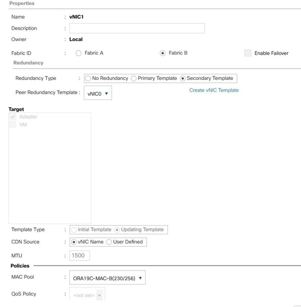
Step 15. Click OK to finish.
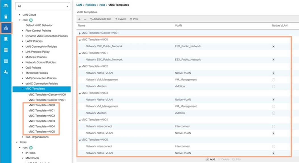
Note: We created vNIC2 and vNIC3 for carrying VM Management and vMotion Traffic in redundancy pairs across both FI.
Step 16. Right-click the vNIC Template and select Create vNIC Template.
Step 17. Enter vNIC2 for the vNIC template name and keep Fabric A selected.
Step 18. For Redundancy Type, select Primary Template since you are going to configure Primary Template as vNIC2 and Secondary Template as vNIC3.
Step 19. Leave the Peer Redundancy Template blank since you will configure this when you create vNIC3 as the peer template of vNIC2.
Step 20. For Template Type, select Updating Template.
Step 21. Under VLANs, check the boxes Native-VLAN, VM_Management, and vMotion. Select VLAN 2 for the Native VLAN.
Step 22. Change MTU value 9000.
Step 23. In the MAC Pool list, select ORA19C-MAC-A.
Step 24. Click OK to create the vNIC2.
Step 25. Right-click the vNIC Template and click Create vNIC Template.
Step 26. Enter vNIC3 for the vNIC template name and keep Fabric B selected
Step 27. For Redundancy Type, select Secondary Template and from the Peer Redundancy Template drop-down list, select vNIC2 to configure Primary & Secondary Redundancy on FI-A and FI-B.
Step 28. For Template Type, select Updating Template and under VLANs, check the boxes Native-VLAN, VM_Management, and vMotion. Select VLAN 2 as Native VLAN.
Step 29. Change MTU value 9000.
Step 30. In the MAC Pool list, select ORA19C-MAC-B and click OK to create the vNIC3 as shown below:

Step 31. Right-click the vNIC Template and select Create vNIC Template.
Step 32. Enter vNIC4 for the vNIC template name and keep Fabric A selected.
Step 33. For Redundancy Type, select Primary Template since you are going to configure the Primary Template as vNIC4 and Secondary Template as vNIC5.
Step 34. Leave the Peer Redundancy Template blank since you will configure this when you create vNIC5 as the peer template of vNIC4.
Step 35. For Template Type, select Updating Template.
Step 36. Under VLANs, check the boxes Native-VLAN and Interconnect. Select VLAN 2 as Native VLAN.
Step 37. Change MTU value 9000.
Step 38. In the MAC Pool list, select ORA19C-MAC-A.
Step 39. Click OK to create the vNIC4.
Step 40. Right-click the vNIC Template and select Create vNIC Template.
Step 41. Enter vNIC5 for the vNIC template name and keep Fabric B selected
Step 42. For the Redundancy Type, select Secondary Template and from the Peer Redundancy Template drop-down list, select vNIC4 to configure Primary & Secondary Redundancy on FI-A and FI-B.
Step 43. For Template Type, select Updating Template and under VLANs, check the boxes Native-VLAN and Interconnect. Select VLAN 2 as Native VLAN.
Step 44. Change MTU value 9000.
Step 45. In the MAC Pool list, select ORA19C-MAC-B and click OK to create the vNIC5 as shown below:

Below is the screenshot of all the vNIC configured for this environment:
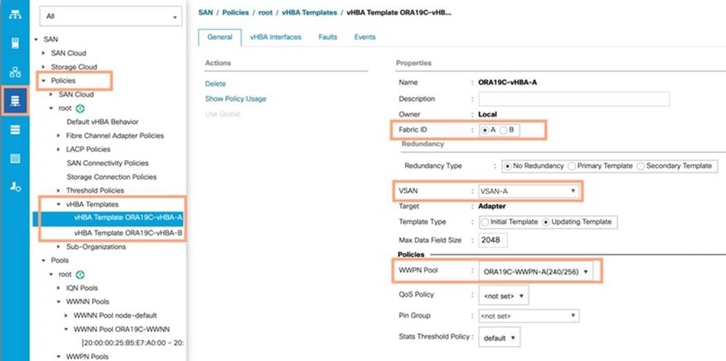
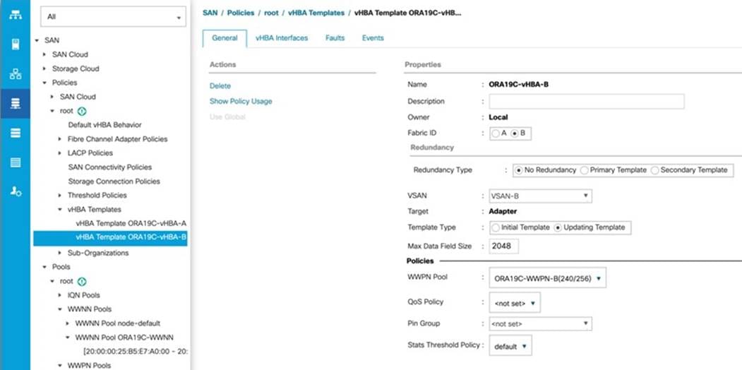
For this solution, we created two vHBA; ORA19C-vHBA-A and ORA19C-vHBA-B.
Procedure 1. Create virtual Host Bus Adapter (vHBA) templates
Step 1. In Cisco UCS Manager, click the SAN tab in the navigation pane.
Step 2. Click Policies > root > right-click vHBA Templates > click Create vHBA Template.
Step 3. Enter the name ORA19C-vHBA-A and keep Fabric A selected.
Step 4. For VSAN, select VSAN-A and template type as Updating Template.
Step 5. For WWPN Pool, select ORA19C-WWPN-A from the drop-down list and click OK to create the first vHBA.
Step 6. Create the second vHBA and change the name to ORA19C-vHBA-B.
Step 7. For the Fabric ID, select B, template type as Updating Template, and WWPN as ORA19C-WWPN-B.
Step 8. Click OK to create second vHBA.
Two vHBA templates have been created as shown below:
Create Local Disk Configuration Policy for Local Disk Boot
Note: For this Cisco Validated Design, we used local disks to install the VMware hypervisor ESXi on all eight blade servers. A Local disk configuration for Cisco UCS is necessary if the servers in the environments have a local disk.
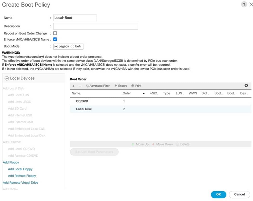
Procedure 1. Create Boot Policies for the Cisco UCS Environments
Step 1. Go to Cisco UCS Manager and then go to Servers > Policies > root > Boot Policies.
Step 2. Right-click and select Create Boot Policy. Enter Local-Boot for the name of the boot policy as shown below:
Note: We used two front disks on each blade server and created a RAID-1 Storage Profile and RAID-1 Storage Policy for high availability in case any disk failure occurs.
| Tech tip |
| You will create the Disk Group Policy first then you will create Storage Profile. |
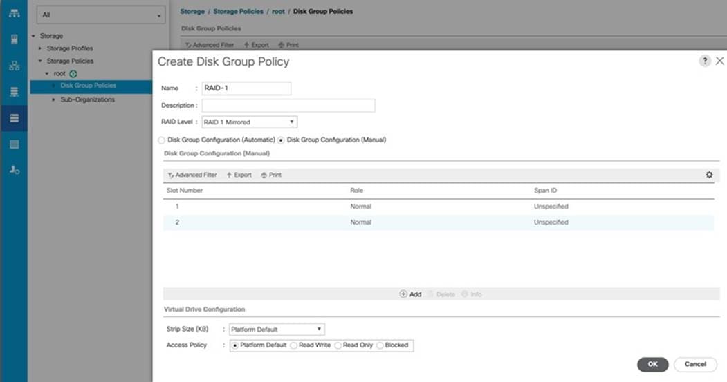
Procedure 1. Create the Disk Group Policy
Step 1. Go to Cisco UCS Manager and click the Storage Tab in the navigation pane.
Step 2. Go to Storage Policies > root > Disk Group Policies.
Step 3. Right-click and select Create Disk Group Policy.
Step 4. Name the Policy “RAID-1” and from the RAID Level drop-down list select RAID 1 Mirrored.
Step 5. Select Disk Group Configuration (Manual) and then click +Add to manually add the disk on slot 1 from the blade server as shown below:
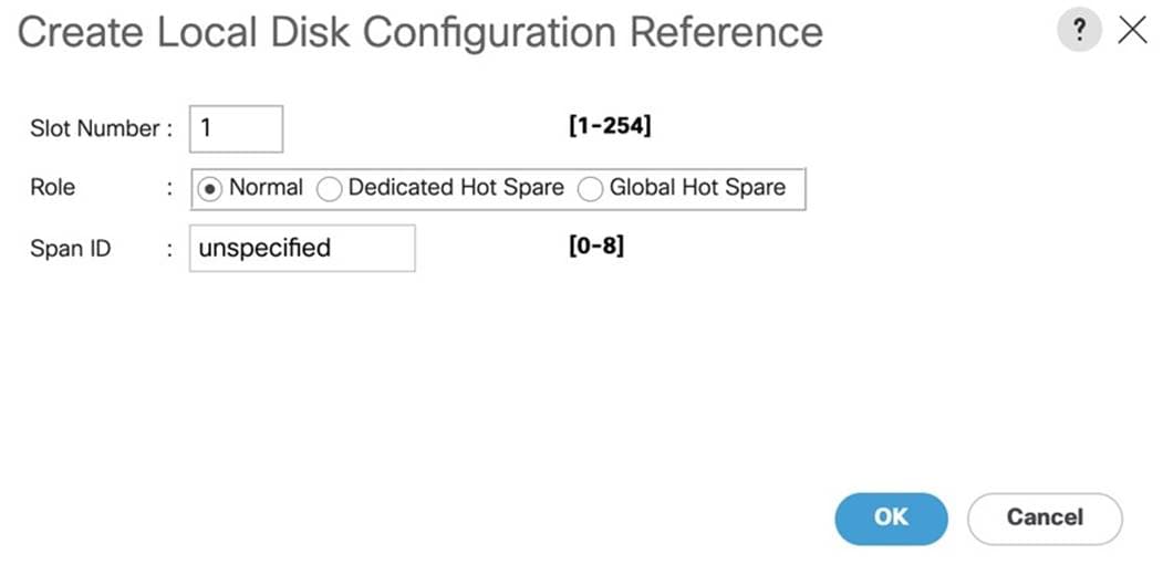
Step 6. Click +Add to manually add the disk on slot 2 from the blade server.
Step 7. Keep the Virtual Drive Configuration options as default and clink OK to create Disk Group Policy as show below:
Procedure 2. Create a Storage Profile for RAID-1
Step 1. Go to Cisco UCS Manager and click the Storage Tab in the navigation pane.
Step 2. Go to Storage Profiles > root > and then right-click Create Storage Profile.
Step 3. Name the Storage Profile “RAID-1” and then click +Add to add Local LUNs into Storage Profile.
Step 4. From the Create Local LUN menu, enter the name “RAID-1” and check the box Expand To Available.
Step 5. For the Select Disk Group Configuration options, select RAID-1 for the Disk Group Policy which you previously created as shown below:
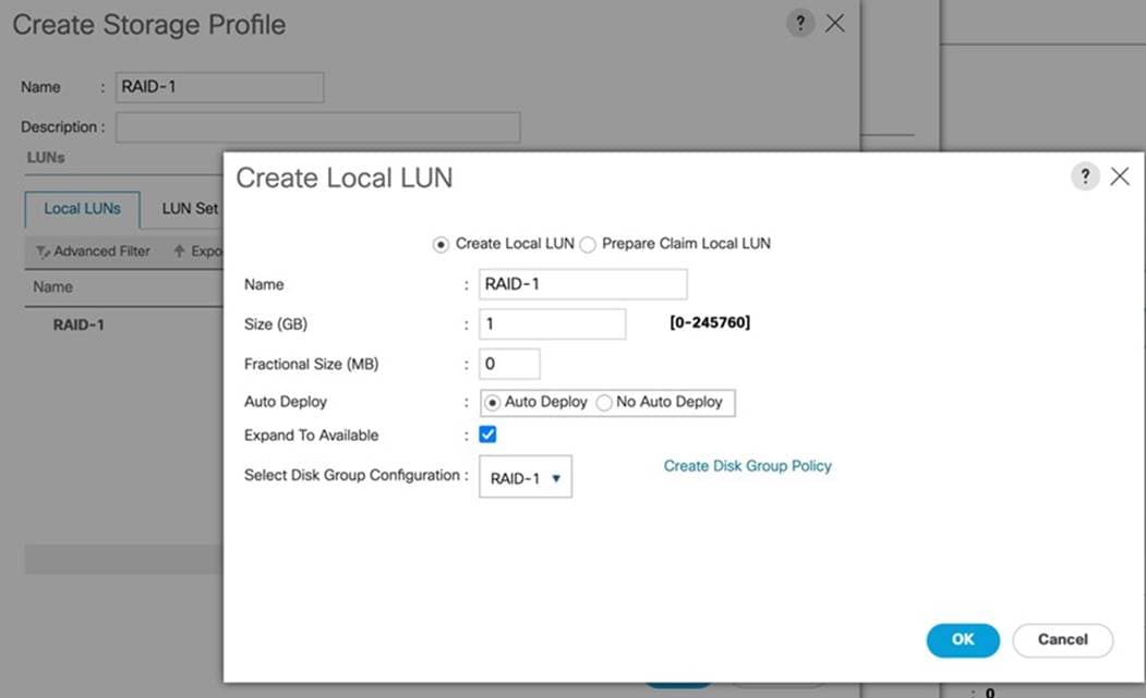
Step 6. Click OK to Create Local LUN and then click OK to finish creating the Storage Profile.
Note: For this solution, we used both slot 1 and slot 2 front disk to create RAID-1 mirrored Local LUN and presented this LUN as the Boot Option for the blade server so that the blade server can boot the OS from this local RAID-1 Volume. We ave installed VMware Hypervisor ESXi on this local RAID-1 Volume for each of the blade servers. We will assign this boot profile and local boot policy to the Service Profiles as explained in the following section.
Create and Configure Service Profile Template
Service profile templates enable policy-based server management that helps ensure consistent server resource provisioning suitable to meet predefined workload needs.
The Cisco UCS service profiles with SAN boot policy provides the following benefits:
● Scalability—Rapid deployment of new servers to the environment in a very few steps.
● Manageability—Enables seamless hardware maintenance and upgrades without any restrictions.
● Flexibility—Easy to repurpose physical servers for different applications and services as needed.
● Availability—Hardware failures are not impactful and critical. In rare case of a server failure, it is easier to associate the logical service profile to another healthy physical server to reduce the impact.
| Tech tip |
| For this solution, you will create one Service Profile Template “ORA19C.” |
Procedure 1. Create Service Profile Template
Step 1. In Cisco UCS go to Servers > Service Profile Templates > root and right-click Create Service Profile Template as shown below:
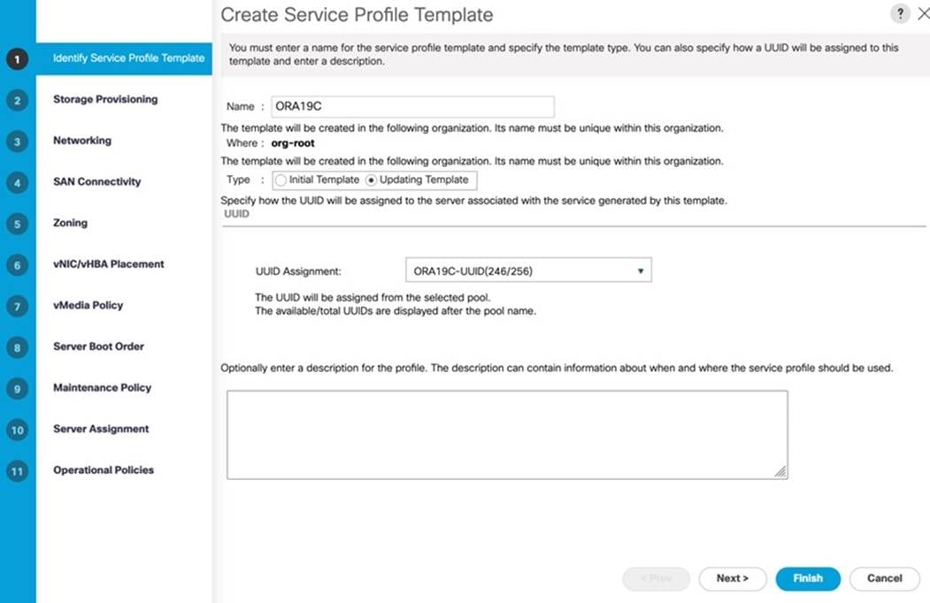
Step 2. For the Service Profile Template name “ORA19C” and select the UUID Pool that was created earlier and click Next.
Step 3. In the Storage Provisioning menu, go to the Storage Profile Policy tab and for the Storage Profile select “RAID-1” as shown below:
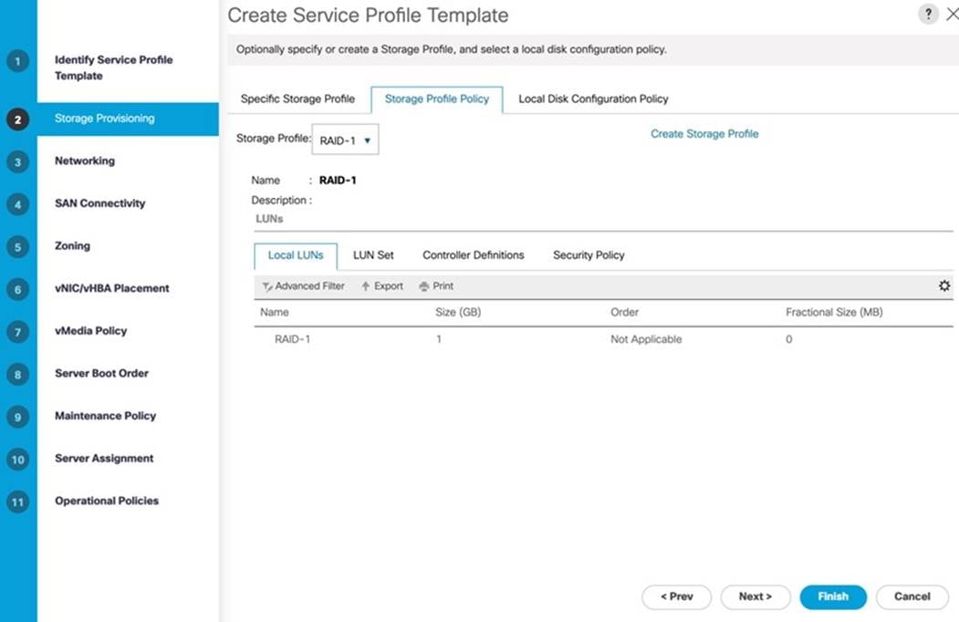
Step 4. Go to the Local Disk Configuration Policy as select the default option for the Local Storage and click Next.
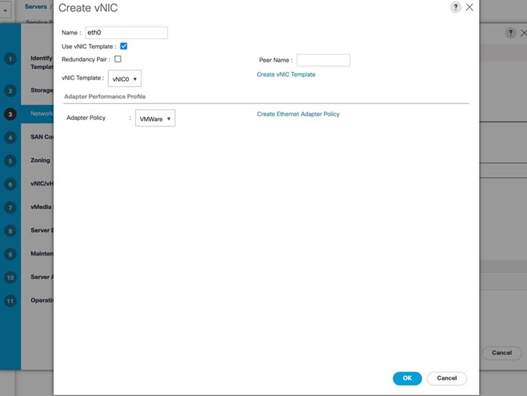
Step 5. In the Networking window, select Expert and click Add to create vNICs that the server should use to connect to the LAN.
Note: In this solution, we created six vNICs as previously explained. We named the first vNIC “eth0” and the second vNIC “eth1”. Similarly, we named the third vNIC as “eth2” and the forth vNIC “eth3”. The fifth vNIC “eth4” and sixth vNIC “eth5” as explained below.
The following six vNIC were created as follows:
● vNIC0 using vNIC Template vNIC0
● vNIC1 using vNIC Template vNIC1
● vNIC2 using vNIC Template vNIC2
● vNIC3 using vNIC Template vNIC3
● vNIC4 and vNIC5 were created using vNIC Template vNIC4 and vNIC Template vNIC5 while these two vNICs used the Adapter Policy “ORA-VMWare” previously created.
● All vNICs use the Adapter Policy “VMWare”
Step 6. In the Create vNIC menu, enter the name “eth0” and check the box “Use vNIC Template.” Select vNIC Template “vNIC0” with the Adapter Policy “VMWare.”
Step 7. Add the second vNIC “eth1” and check the box for “Use vNIC Template.” Select the vNIC Template vNIC1 and Adapter Policy as VMWare.
Step 8. Add the third vNIC “eth2” and check the box for “Use vNIC Template.” Select the vNIC Template vNIC2 and Adapter Policy as VMWare.
Step 9. Add the fourth vNIC “eth3” and check the box for “Use vNIC Template.” Select the vNIC Template vNIC3 and Adapter Policy as VMWare.
Step 10. Add the fifth vNIC “eth4” and check the box for “Use vNIC Template.” Select the vNIC Template vNIC4 and Adapter Policy “ORA-VMWare” previously create for Oracle RAC Private Interconnect Traffic.
Step 11. Add the sixth vNIC “eth5” and check the box for “Use vNIC Template.” Select the vNIC Template vNIC5 and Adapter Policy as “ORA-VMWare”. As shown below, we configured six vNICs as eth0 to eth5 so the servers could connect to the LAN.
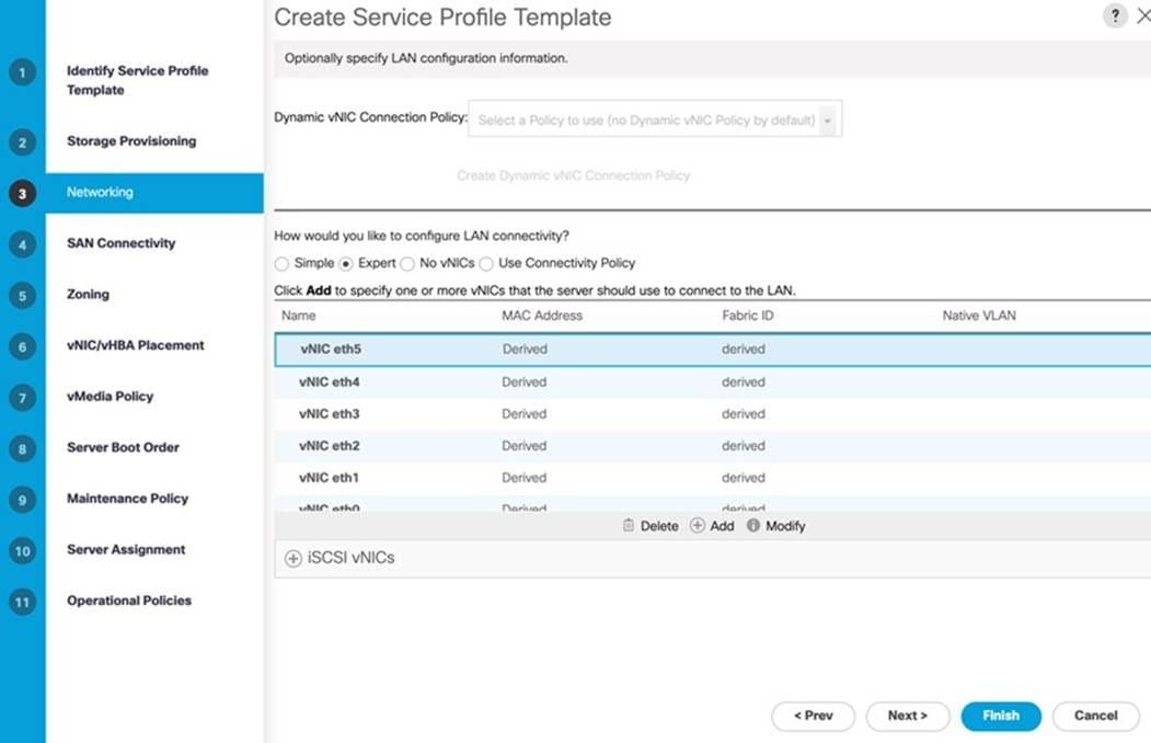
Step 12. When all the vNICs are created and added, click Next.
Step 13. In the SAN Connectivity menu, select Expert to configure the SAN connectivity. Select WWNN (World Wide Node Name) pool ORA19C-WWNN, previously create.
Step 14. Click Add to add vHBAs as shown below:
Note: For this solution, we configured four vHBAs. vHBA0 and vHBA2 are configured to carry FC SAN Network Traffic from FI-A to MDS-A Switch while vHBA1 and vHBA3 are configured for FC SAN Network Traffic from FI-B to MDS-B Switch.
The four vHBAs are as follows:
● vHBA0 and vHBA2 using vHBA Template ORA19C-vHBA-A and FC Adapter Policy as “VMWare”
● vHBA1 and vHBA3 using vHBA Template ORA19C-vHBA-B and FC Adapter Policy as “VMWare”
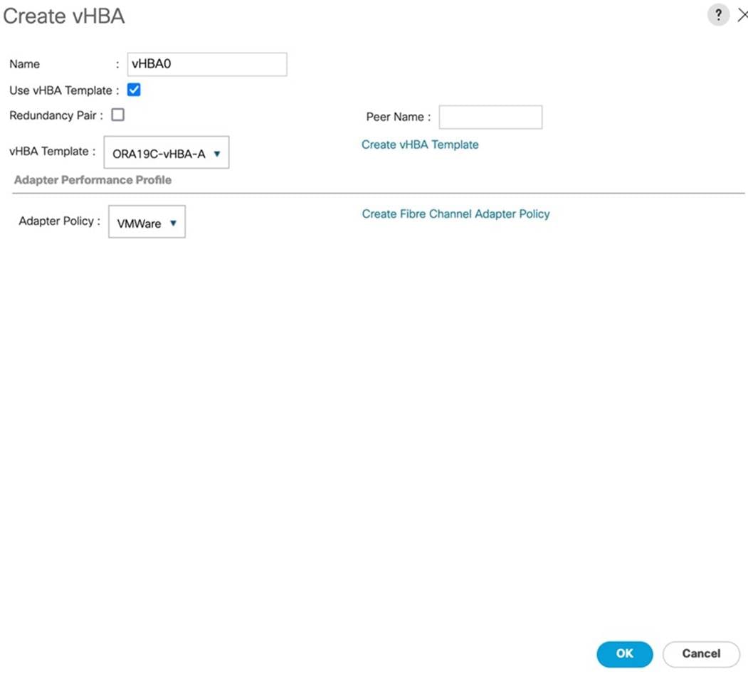
Four vHBAs are configured as shown below:
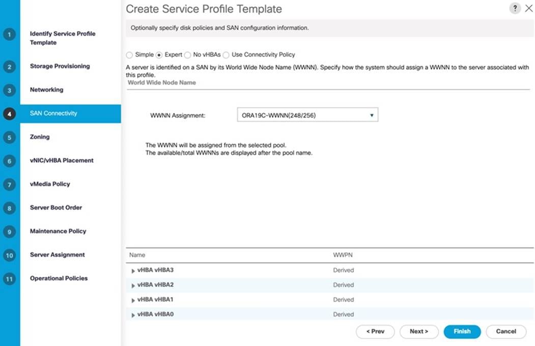
Step 15. Click Next.
Step 16. For this Oracle RAC Configuration, the Cisco MDS 9148T is used for zoning. So, skip zoning and click Next.
Note: For this solution, we placed all NICs and HBAs under vCon1.
Step 17. In the vNIC/vHBA Placement menu, select the Placement options, click Specify Manually.
Step 18. Click vCon1 and select eth0, click >> assign >> to move eth0 under vCon1. Then select eth1 and click >> assign >> to move eth1 under vCon1. Add the remaining eth2, eth3, eth4 and eth5 under the same vCon1 one-by-one.
Step 19. Go to vHBA options and then add vHBA0, vHBA1, vHBA2 and vHBA3 one-by-one under vCon1 as shown below:
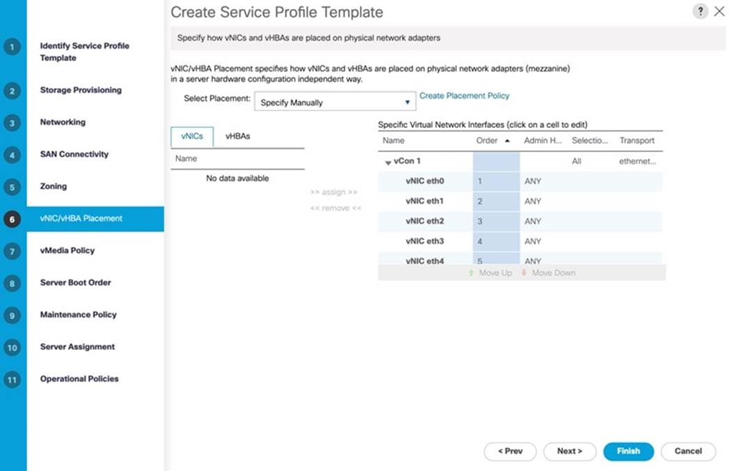
| Tech tip |
| vNIC/vHBA placement on physical network interface is controlled by placement preferences. vNIC/vHBA Placement specifies how vNICs and vHBAs are placed on physical network adapters. |
Step 20. Click Next.
Note: For this solution, we did not configure any vMedia Policy.
Step 21. Click Next.
Step 22. In the Server Boot Order menu, select Local-Boot for the Local Disk Boot Policy which was created earlier and click Next.
Note: The maintenance policy was not selected in this configuration,
Step 23. Click Next.
Step 24. In the Server Assignment menu, from the Firmware Management option, click “4.2-1i” for the Host Firmware Package which was created earlier. Click Next.
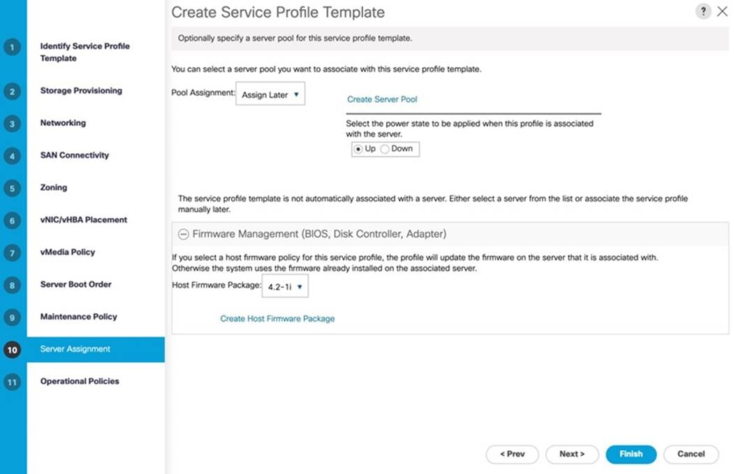
Step 25. In the Operational Policies, select the BIOS Configuration and the BIOS Policy as “ORA-VM” created earlier. Select the Management IP Address options and go to Outband IPv4 and for the Management IP Address Policy, select “ORA19C-KVM” for KVM Access.
Step 26. Click Finish to create Service Profile Template “ORA19C.”
Now you’ve created one Service profile template “ORA19C” having four vHBAs and six vNICs. This service profile template will be used to create eight service profiles for eight ESXi Host named “ORAESX1” to “ORAESX8.” With each ESXi Host, you will create one RHEL VM and all eight VM named “ORAVM1” to “ORAVM8” for hosting eight oracle RAC nodes as explained in the next section.
Create Service Profiles from Template and Associate to Servers
Note: We created eight Service profiles for all eight ESXi Host as explained below.
| Tech tip |
| For all eight ESXi Hosts (ORAESX1, ORAESX2, ORAESX3, ORAESX4, ORAESX5, ORAESX6, ORAESX7 and ORAESX8), you will create eight Service Profiles: ORAESX1, ORAESX2, ORAESX3, ORAESX4, ORAESX5, ORAESX6, ORAESX7 and ORAESX8 from the template “ORA19C.” |
Procedure 1. Create Service Profiles from Template
Step 1. Go to Servers > Service Profiles > root > and right-click Create Service Profiles from Template.
Step 2. Select the Service profile template ORA19C, previously created and name the service profile “ORAESX.”
Step 3. To create eight service profiles, for the Number of Instances enter 8. This process will create service profiles ORAESX1, ORAESX2, ORAESX3, ORAESX4, ORAESX5, ORAESX6, ORAESX7 and ORAESX8.
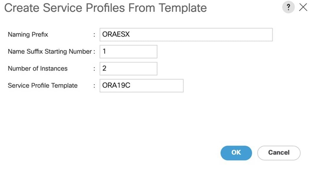
Step 4. When the service profiles are created, associate them to the servers as described in the following section.
Procedure 2. Associate Service Profiles to the Servers
Step 1. Under the server tab, right-click the name of service profile you want to associate with the server and select the option Change Service Profile Association.
Step 2. In the Change Service Profile Association page, from the Server Assignment drop-down list, select the existing server that you would like to assign, and click OK.
Step 3. Make sure all the service profiles are associated.
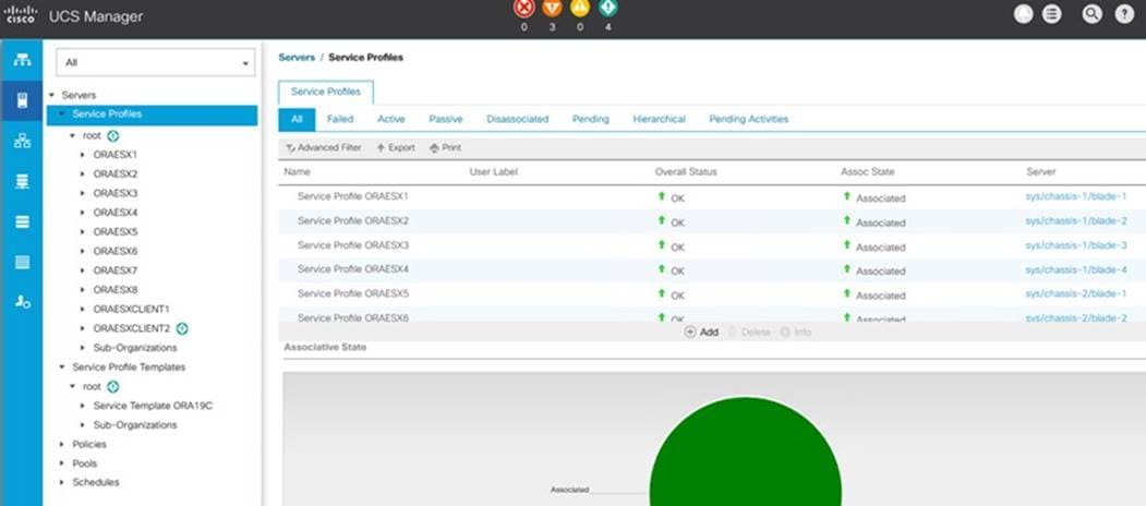
Note: As shown above and below, make sure all server nodes have no major or critical fault and all are in an operable state.
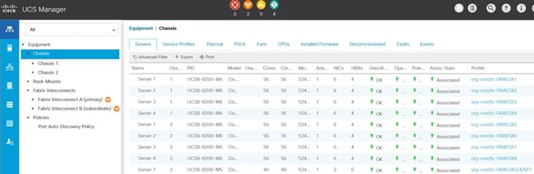
The following service profiles have been assigned:
● Service Profile ORAESX1 to Chassis 1 Server 1
● Service Profile ORAESX2 to Chassis 1 Server 2
● Service Profile ORAESX3 to Chassis 1 Server 3
● Service Profile ORAESX4 to Chassis 1 Server 4
● Service Profiles ORAESX5 to Chassis 2 Server 1
● Service Profile ORAESX6 to Chassis 2 Server 2
● Service Profile ORAESX7 to Chassis 2 Server 3
● Service Profile ORAESX8 to Chassis 2 Server 4
This completes the configuration required for the Cisco UCS Manager Setup.
| Tech tip |
| Additional server pools, service profile templates, and service profiles can be created in the respective organizations to add more servers to the FlashStack unit. All other pools and policies are at the root level and can be shared among the organizations. |
This section provides detailed procedures for configuring the Cisco MDS 9148T Switches.
| Tech tip |
| Follow these steps precisely because failure to do so could result in an improper configuration. |
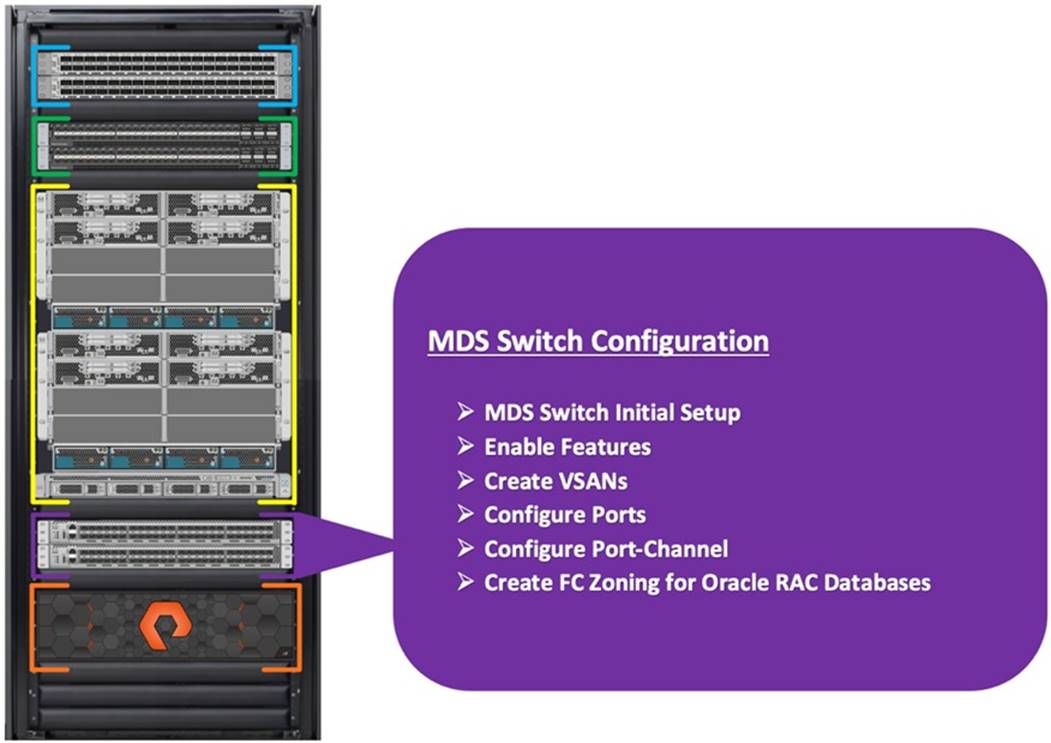
Figure 6 illustrates the connections used in this solution: the MDS Switches to Fabric Interconnects and Pure Storage FlashArray //X90R3 System.
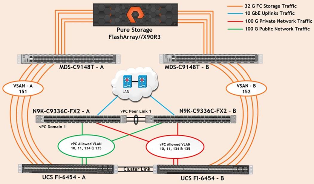
Note: For this solution, we connected four ports (ports 1 to 4) of MDS Switch A to Fabric Interconnect A (ports 1-4). We also connected four ports (ports 1 to 4) of MDS Switch B to Fabric Interconnect B (ports 1-4). All ports carry 32 Gb/s FC Traffic. Table 10 lists the port connectivity of the Cisco MDS Switches to the Fabric Interconnects.
Table 10. MDS Switch Connectivity to Fabric Interconnects
| MDS Switch |
MDS Switch Port |
FI Ports |
Fabric Interconnect |
| MDS Switch A |
FC Port 1/1 |
FI-A Port 1/1 |
Fabric Interconnect A (FI-A) |
| FC Port 1/2 |
FI-A Port 1/2 |
||
| FC Port 1/3 |
FI-A Port 1/3 |
||
| FC Port 1/4 |
FI-A Port 1/4 |
||
| MDS Switch B |
FC Port 1/1 |
FI-B Port 1/1 |
Fabric Interconnect B (FI-B) |
| FC Port 1/2 |
FI-B Port 1/2 |
||
| FC Port 1/3 |
FI-B Port 1/3 |
||
| FC Port 1/4 |
FI-B Port 1/4 |
Note: For this solution, we connected four ports (ports 5 to 8) of MDS Switch A to the Pure Storage //X90R3 Storage controller. We also connected four ports (ports 5 to 8) of MDS Switch B to the Pure Storage //X90R3 Storage controller. All ports carry 32 Gb/s FC Traffic. Table 11 lists the port connectivity of the Cisco MDS Switches to Pure FlashArray //X90R3 Controller.
Table 11. MDS Switch Connectivity to the Pure Storage FlashArray //X90R3
| MDS Switch |
MDS Switch Port |
Pure Storage Controller |
Pure Storage Controller Ports |
| MDS Switch A
|
FC Port 1/5 |
Pure Storage FA-X90R3 Controller 0 |
CT0.FC0 |
| FC Port 1/6 |
Pure Storage FA-X90R3 Controller 0 |
CT0.FC8 |
|
| FC Port 1/7 |
Pure Storage FA-X90R3 Controller 1 |
CT1.FC0 |
|
| FC Port 1/8 |
Pure Storage FA-X90R3 Controller 1 |
CT1.FC8 |
|
| MDS Switch B |
FC Port 1/5 |
Pure Storage FA-X90R3 Controller 0 |
CT0.FC1 |
| FC Port 1/6 |
Pure Storage FA-X90R3 Controller 0 |
CT0.FC9 |
|
| FC Port 1/7 |
Pure Storage FA-X90R3 Controller 1 |
CT1.FC1 |
|
| FC Port 1/8 |
Pure Storage FA-X90R3 Controller 1 |
CT1.FC9 |
Procedure 1. Configure Features
Step 1. Login as admin user into the MDS Switch A and MDS Switch B and run the following commands:
config terminal
feature npiv
feature fport-channel-trunk
copy running-config startup-config
Procedure 2. Configure VSANs and Ports
Step 1. Login as admin user into MDS Switch A.
Step 2. Create VSAN 151 for Storage Traffic and configure ports by running the following commands:
config terminal
vsan database
vsan 151
vsan 151 name "VSAN-FI-A"
vsan 151 interface fc 1/1-12
zone smart-zoning enable vsan 151
exit
interface port-channel 251
switchport trunk allowed vsan 151
switchport description ORA19C-FSVM-FI-A
switchport rate-mode dedicated
switchport trunk mode off
no shutdown
interface fc1/1
switchport description ORA19C-FSVM-FI-A-1/1
switchport trunk mode off
port-license acquire
channel-group 251 force
no shutdown
interface fc1/2
switchport description ORA19C-FSVM-FI-A-1/2
switchport trunk mode off
port-license acquire
channel-group 251 force
no shutdown
interface fc1/3
switchport description ORA19C-FSVM-FI-A-1/3
switchport trunk mode off
port-license acquire
channel-group 251 force
no shutdown
interface fc1/4
switchport description ORA19C-FSVM-FI-A-1/4
switchport trunk mode off
port-license acquire
channel-group 251 force
no shutdown
interface fc1/5
switchport trunk allowed vsan 151
switchport description OracleRACNVMe-FA01-CT0.FC0
switchport trunk mode off
port-license acquire
no shutdown
interface fc1/6
switchport trunk allowed vsan 151
switchport description OracleRACNVMe-FA01-CT0.FC8
switchport trunk mode off
port-license acquire
no shutdown
interface fc1/7
switchport trunk allowed vsan 151
switchport description OracleRACNVMe-FA01-CT1.FC0
switchport trunk mode off
port-license acquire
no shutdown
interface fc1/8
switchport trunk allowed vsan 151
switchport description OracleRACNVMe-FA01-CT1.FC8
switchport trunk mode off
port-license acquire
no shutdown
copy running-config startup-config
exit
Step 3. Login as admin user into MDS Switch B.
Step 4. Create VSAN 152 for Storage Traffic and configure ports by running the following commands:
config terminal
vsan database
vsan 152
vsan 152 name "VSAN-FI-B"
vsan 152 interface fc 1/1-12
zone smart-zoning enable vsan 152
exit
interface port-channel 252
switchport trunk allowed vsan 152
switchport description ORA19C-FSVM-FI-B
switchport rate-mode dedicated
switchport trunk mode off
interface fc1/1
switchport description ORA19C-FSVM-FI-B-1/1
switchport trunk mode off
port-license acquire
channel-group 252 force
no shutdown
interface fc1/2
switchport description ORA19C-FSVM-FI-B-1/2
switchport trunk mode off
port-license acquire
channel-group 252 force
no shutdown
interface fc1/3
switchport description ORA19C-FSVM-FI-B-1/3
switchport trunk mode off
port-license acquire
channel-group 252 force
no shutdown
interface fc1/4
switchport description ORA19C-FSVM-FI-B-1/4
switchport trunk mode off
port-license acquire
channel-group 252 force
no shutdown
interface fc1/5
switchport trunk allowed vsan 152
switchport description OracleRACNVMe-FA01-CT0.FC1
switchport trunk mode off
port-license acquire
no shutdown
interface fc1/6
switchport trunk allowed vsan 152
switchport description OracleRACNVMe-FA01-CT0.FC9
switchport trunk mode off
port-license acquire
no shutdown
interface fc1/7
switchport trunk allowed vsan 152
switchport description OracleRACNVMe-FA01-CT1.FC1
switchport trunk mode off
port-license acquire
no shutdown
interface fc1/8
switchport trunk allowed vsan 152
switchport description OracleRACNVMe-FA01-CT1.FC9
switchport trunk mode off
port-license acquire
no shutdown
copy running-config startup-config
exit
Procedure 3. Configure Zoning
This procedure sets up the Fibre Channel connections between the Cisco MDS 9148T switches, the Cisco UCS Fabric Interconnects, and the Pure Storage FlashArray //X90R3 systems.
| Tech tip |
| Before you configure the zoning details, decide how many paths are needed for each volume and extract the WWPN numbers for each of the HBAs from each server. |
For this solution, we created 4 vHBAs on each server node. As listed in Table 3 and section Create and Configure Service Profile Template, we configured vHBA0 and vHBA2 to carry FC Network Traffic from FI-A to MDS-A and we also configured vHBA1 and vHBA3 to carry FC Network Traffic from FI-B to MDS-B Switch.
Step 1. Log into the Cisco UCS Manager > Servers > Service Profiles > root > and then select the desired server. Click on the first serve profile “ORAESX1” and expand the tab underneath to get HBA and WWPN details as shown below:

Step 2. Log into the Pure Storage FlashArray and extract the WWPN of FC ports and verify all the port information is correct. This information can be found in the Pure Storage GUI under Health > Connection > Array Ports as shown below:
| Tech tip |
| You can also obtain this information by login to the storage cluster management IP address. |
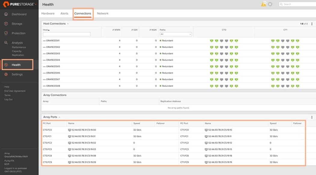
Procedure 4. Create Device Aliases for Zoning on MDS Switch A
Step 1. Login as admin user and run the following commands MDS switch A:
configure terminal
device-alias database
device-alias name ORAESX1-hba0 pwwn 20:00:00:25:b5:e7:aa:00
device-alias name ORAESX1-hba2 pwwn 20:00:00:25:b5:e7:aa:01
device-alias name ORAESX2-hba0 pwwn 20:00:00:25:b5:e7:aa:02
device-alias name ORAESX2-hba2 pwwn 20:00:00:25:b5:e7:aa:03
device-alias name ORAESX3-hba0 pwwn 20:00:00:25:b5:e7:aa:04
device-alias name ORAESX3-hba2 pwwn 20:00:00:25:b5:e7:aa:05
device-alias name ORAESX4-hba0 pwwn 20:00:00:25:b5:e7:aa:06
device-alias name ORAESX4-hba2 pwwn 20:00:00:25:b5:e7:aa:07
device-alias name ORAESX5-hba0 pwwn 20:00:00:25:b5:e7:aa:08
device-alias name ORAESX5-hba2 pwwn 20:00:00:25:b5:e7:aa:09
device-alias name ORAESX6-hba0 pwwn 20:00:00:25:b5:e7:aa:0a
device-alias name ORAESX6-hba2 pwwn 20:00:00:25:b5:e7:aa:0b
device-alias name ORAESX7-hba0 pwwn 20:00:00:25:b5:e7:aa:0c
device-alias name ORAESX7-hba2 pwwn 20:00:00:25:b5:e7:aa:0d
device-alias name ORAESX8-hba0 pwwn 20:00:00:25:b5:e7:aa:0e
device-alias name ORAESX8-hba2 pwwn 20:00:00:25:b5:e7:aa:0f
device-alias name OracleRACNVMe-FA01-CT0-FC0 pwwn 52:4a:93:7b:31:c5:19:00
device-alias name OracleRACNVMe-FA01-CT0-FC8 pwwn 52:4a:93:7b:31:c5:19:08
device-alias name OracleRACNVMe-FA01-CT1-FC0 pwwn 52:4a:93:7b:31:c5:19:10
device-alias name OracleRACNVMe-FA01-CT1-FC8 pwwn 52:4a:93:7b:31:c5:19:18
device-alias commit
copy run start
Procedure 5. Create Device Aliases for Zoning on MDS Switch B
Step 1. Login as admin user and run the following commands on MDS switch B:
configure terminal
device-alias database
device-alias name ORAESX1-hba1 pwwn 20:00:00:25:b5:e7:ab:00
device-alias name ORAESX1-hba3 pwwn 20:00:00:25:b5:e7:ab:01
device-alias name ORAESX2-hba1 pwwn 20:00:00:25:b5:e7:ab:02
device-alias name ORAESX2-hba3 pwwn 20:00:00:25:b5:e7:ab:03
device-alias name ORAESX3-hba1 pwwn 20:00:00:25:b5:e7:ab:04
device-alias name ORAESX3-hba3 pwwn 20:00:00:25:b5:e7:ab:05
device-alias name ORAESX4-hba1 pwwn 20:00:00:25:b5:e7:ab:06
device-alias name ORAESX4-hba3 pwwn 20:00:00:25:b5:e7:ab:07
device-alias name ORAESX5-hba1 pwwn 20:00:00:25:b5:e7:ab:08
device-alias name ORAESX5-hba3 pwwn 20:00:00:25:b5:e7:ab:09
device-alias name ORAESX6-hba1 pwwn 20:00:00:25:b5:e7:ab:0a
device-alias name ORAESX6-hba3 pwwn 20:00:00:25:b5:e7:ab:0b
device-alias name ORAESX7-hba1 pwwn 20:00:00:25:b5:e7:ab:0c
device-alias name ORAESX7-hba3 pwwn 20:00:00:25:b5:e7:ab:0d
device-alias name ORAESX8-hba1 pwwn 20:00:00:25:b5:e7:ab:0e
device-alias name ORAESX8-hba3 pwwn 20:00:00:25:b5:e7:ab:0f
device-alias name OracleRACNVMe-FA01-CT0-FC1 pwwn 52:4a:93:7b:31:c5:19:01
device-alias name OracleRACNVMe-FA01-CT0-FC9 pwwn 52:4a:93:7b:31:c5:19:09
device-alias name OracleRACNVMe-FA01-CT1-FC1 pwwn 52:4a:93:7b:31:c5:19:11
device-alias name OracleRACNVMe-FA01-CT1-FC9 pwwn 52:4a:93:7b:31:c5:19:19
device-alias commit
copy run start
Procedure 6. Create Zoning for FC on Cisco MDS Switch A
Step 1. Login as admin user.
Step 2. Create the zones for each server:
configure terminal
zone name ORAESX1A vsan 151
member pwwn ORAESX1-hba0 init
member pwwn ORAESX1-hba2 init
member pwwn OracleRACNVMe-FA01-CT0-FC0 target
member pwwn OracleRACNVMe-FA01-CT0-FC8 target
member pwwn OracleRACNVMe-FA01-CT1-FC0 target
member pwwn OracleRACNVMe-FA01-CT1-FC8 target
zone name ORAESX2A vsan 151
member pwwn ORAESX2-hba0 init
member pwwn ORAESX2-hba2 init
member pwwn OracleRACNVMe-FA01-CT0-FC0 target
member pwwn OracleRACNVMe-FA01-CT0-FC8 target
member pwwn OracleRACNVMe-FA01-CT1-FC0 target
member pwwn OracleRACNVMe-FA01-CT1-FC8 target
zone name ORAESX3A vsan 151
member pwwn ORAESX3-hba0 init
member pwwn ORAESX3-hba2 init
member pwwn OracleRACNVMe-FA01-CT0-FC0 target
member pwwn OracleRACNVMe-FA01-CT0-FC8 target
member pwwn OracleRACNVMe-FA01-CT1-FC0 target
member pwwn OracleRACNVMe-FA01-CT1-FC8 target
zone name ORAESX4A vsan 151
member pwwn ORAESX4-hba0 init
member pwwn ORAESX4-hba2 init
member pwwn OracleRACNVMe-FA01-CT0-FC0 target
member pwwn OracleRACNVMe-FA01-CT0-FC8 target
member pwwn OracleRACNVMe-FA01-CT1-FC0 target
member pwwn OracleRACNVMe-FA01-CT1-FC8 target
zone name ORAESX5A vsan 151
member pwwn ORAESX5-hba0 init
member pwwn ORAESX5-hba2 init
member pwwn OracleRACNVMe-FA01-CT0-FC0 target
member pwwn OracleRACNVMe-FA01-CT0-FC8 target
member pwwn OracleRACNVMe-FA01-CT1-FC0 target
member pwwn OracleRACNVMe-FA01-CT1-FC8 target
zone name ORAESX6A vsan 151
member pwwn ORAESX6-hba0 init
member pwwn ORAESX6-hba2 init
member pwwn OracleRACNVMe-FA01-CT0-FC0 target
member pwwn OracleRACNVMe-FA01-CT0-FC8 target
member pwwn OracleRACNVMe-FA01-CT1-FC0 target
member pwwn OracleRACNVMe-FA01-CT1-FC8 target
zone name ORAESX7A vsan 151
member pwwn ORAESX7-hba0 init
member pwwn ORAESX7-hba2 init
member pwwn OracleRACNVMe-FA01-CT0-FC0 target
member pwwn OracleRACNVMe-FA01-CT0-FC8 target
member pwwn OracleRACNVMe-FA01-CT1-FC0 target
member pwwn OracleRACNVMe-FA01-CT1-FC8 target
zone name ORAESX8A vsan 151
member pwwn ORAESX8-hba0 init
member pwwn ORAESX8-hba2 init
member pwwn OracleRACNVMe-FA01-CT0-FC0 target
member pwwn OracleRACNVMe-FA01-CT0-FC8 target
member pwwn OracleRACNVMe-FA01-CT1-FC0 target
member pwwn OracleRACNVMe-FA01-CT1-FC8 target
Add all the members into Zoneset:
zoneset name ORAESX-A vsan 151
member ORAESX1A
member ORAESX2A
member ORAESX3A
member ORAESX4A
member ORAESX5A
member ORAESX6A
member ORAESX7A
member ORAESX8A
Activate the Zoneset and save the configuration.
zoneset activate name ORAESX-A vsan 151
copy run start
Procedure 7. Create Zoning for FC on Cisco MDS Switch B
Step 1. Login as admin user.
Step 2. Create the zones for each server:
configure terminal
zone name ORAESX1B vsan 152
member pwwn ORAESX1-hba1 init
member pwwn ORAESX1-hba3 init
member pwwn OracleRACNVMe-FA01-CT0-FC1 target
member pwwn OracleRACNVMe-FA01-CT0-FC9 target
member pwwn OracleRACNVMe-FA01-CT1-FC1 target
member pwwn OracleRACNVMe-FA01-CT1-FC9 target
zone name ORAESX2B vsan 152
member pwwn ORAESX2-hba1 init
member pwwn ORAESX2-hba3 init
member pwwn OracleRACNVMe-FA01-CT0-FC1 target
member pwwn OracleRACNVMe-FA01-CT0-FC9 target
member pwwn OracleRACNVMe-FA01-CT1-FC1 target
member pwwn OracleRACNVMe-FA01-CT1-FC9 target
zone name ORAESX3B vsan 152
member pwwn ORAESX3-hba1 init
member pwwn ORAESX3-hba3 init
member pwwn OracleRACNVMe-FA01-CT0-FC1 target
member pwwn OracleRACNVMe-FA01-CT0-FC9 target
member pwwn OracleRACNVMe-FA01-CT1-FC1 target
member pwwn OracleRACNVMe-FA01-CT1-FC9 target
zone name ORAESX4B vsan 152
member pwwn ORAESX4-hba1 init
member pwwn ORAESX4-hba3 init
member pwwn OracleRACNVMe-FA01-CT0-FC1 target
member pwwn OracleRACNVMe-FA01-CT0-FC9 target
member pwwn OracleRACNVMe-FA01-CT1-FC1 target
member pwwn OracleRACNVMe-FA01-CT1-FC9 target
zone name ORAESX5B vsan 152
member pwwn ORAESX5-hba1 init
member pwwn ORAESX5-hba3 init
member pwwn OracleRACNVMe-FA01-CT0-FC1 target
member pwwn OracleRACNVMe-FA01-CT0-FC9 target
member pwwn OracleRACNVMe-FA01-CT1-FC1 target
member pwwn OracleRACNVMe-FA01-CT1-FC9 target
zone name ORAESX6B vsan 152
member pwwn ORAESX6-hba1 init
member pwwn ORAESX6-hba3 init
member pwwn OracleRACNVMe-FA01-CT0-FC1 target
member pwwn OracleRACNVMe-FA01-CT0-FC9 target
member pwwn OracleRACNVMe-FA01-CT1-FC1 target
member pwwn OracleRACNVMe-FA01-CT1-FC9 target
zone name ORAESX7B vsan 152
member pwwn ORAESX7-hba1 init
member pwwn ORAESX7-hba3 init
member pwwn OracleRACNVMe-FA01-CT0-FC1 target
member pwwn OracleRACNVMe-FA01-CT0-FC9 target
member pwwn OracleRACNVMe-FA01-CT1-FC1 target
member pwwn OracleRACNVMe-FA01-CT1-FC9 target
zone name ORAESX8B vsan 152
member pwwn ORAESX8-hba1 init
member pwwn ORAESX8-hba3 init
member pwwn OracleRACNVMe-FA01-CT0-FC1 target
member pwwn OracleRACNVMe-FA01-CT0-FC9 target
member pwwn OracleRACNVMe-FA01-CT1-FC1 target
member pwwn OracleRACNVMe-FA01-CT1-FC9 target
Step 3. Create Zoneset and add all the members:
zoneset name ORAESX-B vsan 152
member ORAESX1B
member ORAESX2B
member ORAESX3B
member ORAESX4B
member ORAESX5B
member ORAESX6B
member ORAESX7B
member ORAESX8B
Step 4. Activate the Zoneset and save the configuration:
zoneset activate name ORAESX-B vsan 152
copy run start
Procedure 8. Verify FC Ports on MDS Switch
Step 1. Login as admin user into MDS Switch A and run the “show flogi database vsan 151” to verify all FC ports:
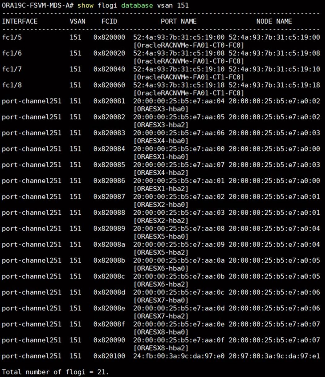
Step 2. Login as admin user into MDS Switch B and run the “show flogi database vsan 152” to verify all FC ports:
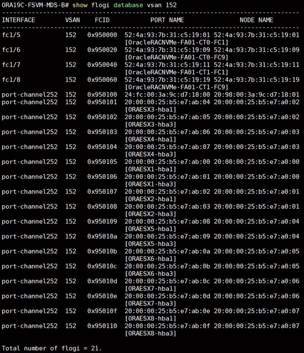
This concludes both MDS Switch configurations.
Configure Pure FlashArray //X90R3 Storage
Figure 7 shows the high-level steps to configure the Pure FlashArray Storage for this solution.
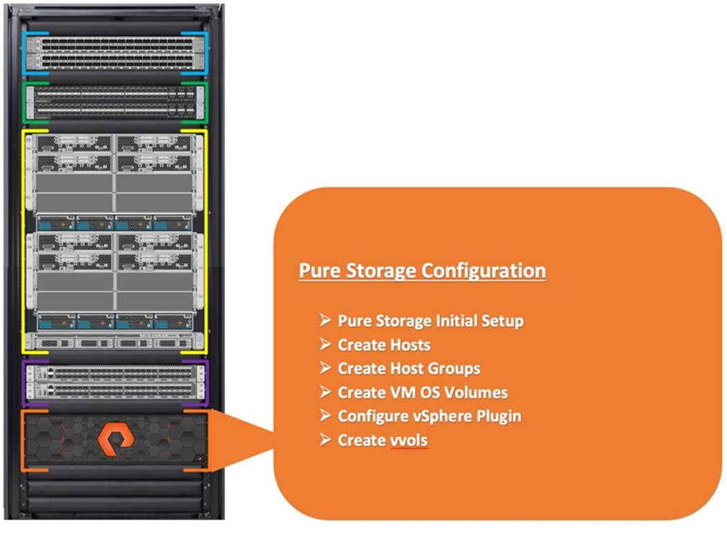
Note: For the initial Pure Storage configuration and configuring the management network access according to your environment, please contact Pure Storage Support.
This section describes the high-level steps to configure Pure Storage FlashArray//X90 R3 used in this solution. For this solution, Pure Storage FlashArray was loaded with Purity//FA Version 6.1.11 which is recommended by Pure Storage. The hosts were redundantly connected to the storage controllers through 8 x 32Gb connections (4 x 32Gb per storage controller module) from the redundant Cisco MDS 9148T switches to access database storage from all the ESXi and RHEL VM Oracle RAC nodes. Please refer to section Configure Cisco MDS Switches, for more details on storage to MDS connectivity.
Note: It is beyond the scope of this document to include all configuration procedures of Pure Storage. We will highlight only partial steps to configure the array to deploy this solution and configure SAN connectivity. Please refer to the Pure Storage Support to configure accordingly to your environment.
For FlashArray VMware best practices, go to: https://support.purestorage.com/Solutions/VMware_Platform_Guide/User_Guides_for_VMware_Solutions/FlashArray_VMware_Best_Practices_User_Guide/hhhWeb_Guide%3A_FlashArray_VMware_Best_Practices
For FlashArray Configuration, go to: https://support.purestorage.com/Solutions/VMware_Platform_Guide/User_Guides_for_VMware_Solutions/FlashArray_VMware_Best_Practices_User_Guide/bbbFlashArray_Configuration
For ESXi Host Configuration, go to: https://support.purestorage.com/Solutions/VMware_Platform_Guide/User_Guides_for_VMware_Solutions/FlashArray_VMware_Best_Practices_User_Guide/dddVMware_ESXi_Host_Configuration
Procedure 1. Create Hosts and Hosts Group
A host is a collection of initiators (Fibre Channel WWPNs, iSCSI IQNs or NVMe NQNs) that refers to a physical host. A FlashArray host object must have a one-to-one relationship with an ESXi host.
Step 1. Go to Pure Storage Management GUI and then navigate to the Storage tab and click Hosts.
Step 2. Click the “+” sign to create host.
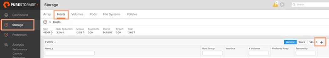
Step 3. For the Host name, enter ORA19CESX1 and for Personality, select ESXi from the drop-down list.
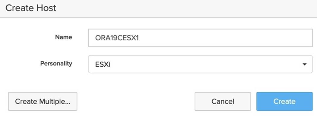
Step 4. Go to host “ORA19CESX1” host and then from the right-side menu option click “Configure WWNs...” which will display a window with the available WWNs on the left side. Every active initiator for a given ESXi host should be added to the respective FlashArray host object. Also verify the UCS Server Hosts WWPNs as shown in the following screenshot.
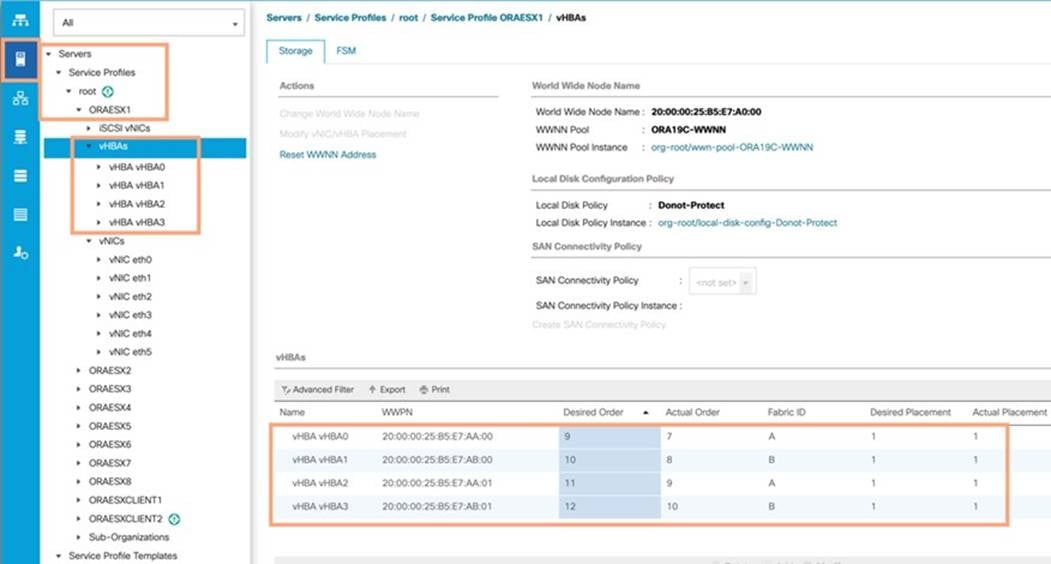
| Tech tip |
| WWNs will appear only if the appropriate FC connections were made, and the zones were setup on the underlying FC switch. |
Step 5. Repeat steps 1 – 4 when the ESXi Host 1 is configured with their FC interfaces, to create the remaining seven ESXi Hosts ORA19CESX2 to ORA19CESX8 and add their WWPNs accordingly.
| Tech tip |
| Pure Storage recommends grouping your ESXi hosts into clusters within vCenter—since this provides a variety of benefits like High Availability and Dynamic Resource Scheduling. To provide simple provisioning, Pure Storage also recommends creating host groups that correspond to VMware clusters. Therefore, with every VMware cluster that will use FlashArray storage, a respective host group should be created. Every ESXi host that is in the cluster should have a corresponding host (as described above) that is added to a host group. |
Step 6. Create Host Group by going to the Storage tab and from the right-side menu options click on Hosts. Click the “+” sign from the right-side menu Host Groups to create Host Group as shown below:
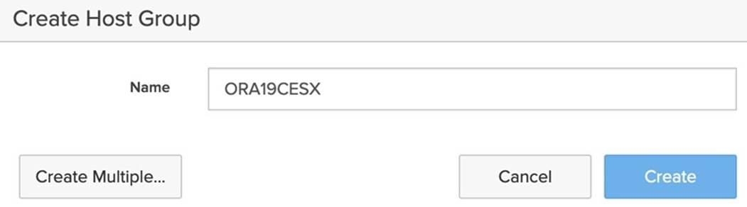
Step 7. Go to Host Group “ORA19CESX” and then add all eight hosts members ORA19CESX1 to ORA19CESX8 into Member Hosts by going to right-side options and click Add.
Note: For this solution, we created 8 volumes and assigned them to Host Group “ORA19CESX” to create eight Virtual Machines and then installed Red Hat Enterprise Linux on those VM’s on a shared datastore across all eight ESXi Hosts. For database deployment, we configured storage array to add vSphere Plugin and added this storage array to access through vSphere datastore and then configured the datastore “vVol” to create all the databases.
Operating System and Database Deployment
This chapter is organized into the following subjects:
The design goal of the reference architecture is to best represent a real-world environment as closely as possible. A service profile was created within Cisco UCS Manager to rapidly deploy all the stateless servers to deploy VMware ESXi hypervisor on eight server nodes.
For this solution, we configured the local virtual drive (local raid volume) on each of the blade server as explained in section Configure LAN and SAN on Cisco USC Manager. On that local virtual drive, we installed VMware hypervisor ESXi 7.0.2 and each ESXi Server Node was configured with one Virtual Machine running Red Hat Enterprise Linux 7.9 (3.10.0-1160.el7.x86_64). All eight RHEL VM OS’s were provisioned on shared datastore across all eight ESXi hosts from Pure Storage Array. We configured Oracle Database 19c Grid Infrastructure and Oracle Database 19c software to create an eight node Oracle Multitenant RAC 19c database solution on these eight VM’s as explained below.
Figure 8 shows the high-level steps to configure ESXi and VM Linux Hosts and deploy the Oracle RAC Database solution.
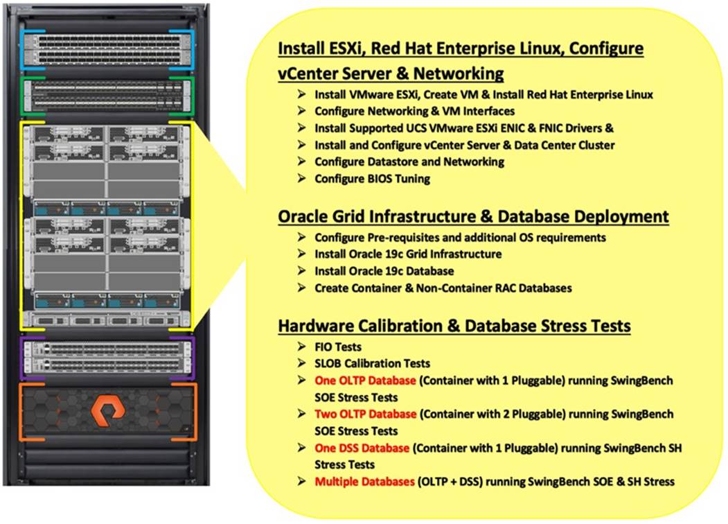
Note: The detailed installation process is not contained in this document, but the following section describes the key steps for VMware vSphere installation.
Procedure 1. Configure Host with ESXi 7
Step 1. The VMware Cisco Custom Image is needed during installation by manual access to the Cisco UCS KVM vMedia, or through a vMedia. Please download the ISO file Cisco custom ESXi 7.0.U2 here: https://customerconnect.vmware.com/downloads/details?downloadGroup=OEM-ESXI70U2-CISCO&productId=974
Step 2. Go to Cisco UCS Manager and launch the KVM console on the desired server; go to Equipment > Chassis > Chassis 1 > Servers > Server 1 > from right-side window, go to General > and select KVM Console to open KVM.
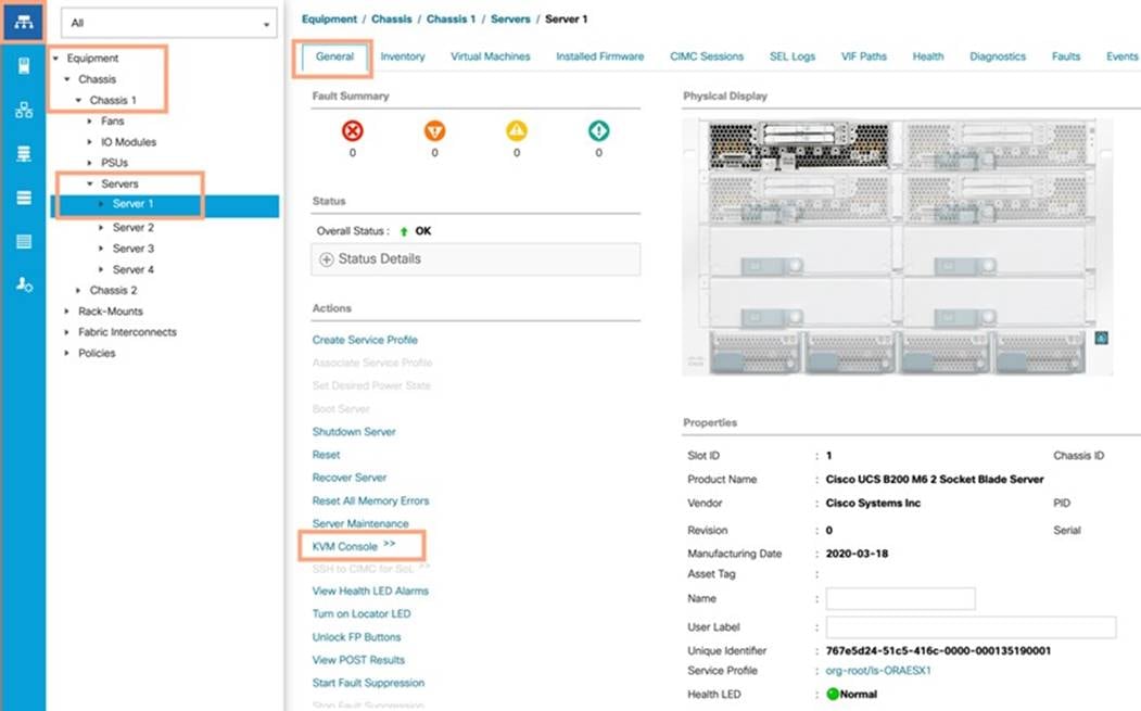
Step 3. Click Accept security and open KVM. In the KVM window, click the Virtual Media Icon > Activate Virtual Devices > Map CD/DVD. Browse to the ESXi installed ISO image file and click Open. Click Map devices. Boot the server by clicking Power > Power Cycle System and monitor the server boot.
Step 4. When the Server starts booting, the machine detects the presence of the ESXi installation media. Select the ESXi installer from the boot menu that is displayed.
Step 5. After the installer is finished loading, press Enter to continue with the installation. Read and accept the end-user license agreement (EULA). Press F11 to accept and continue.
Step 6. Click the Virtual Drive that was previously set up as the installation disk for ESXi and press Enter to continue with the installation.
Step 7. Click the appropriate keyboard layout and press Enter.
Step 8. Enter and confirm the root password and press Enter. The installer issues a warning that the selected disk will be repartitioned. Press F11 to continue with the installation.
Step 9. From the KVM window, press Enter to reboot the server.
| Tech tip |
| Adding a management network to each VMware host is necessary for managing the host. |
Procedure 2. Add a Management Network for the VMware Hosts
Step 1. After the server has finished rebooting, press F2 to customize the system.
Step 2. Log in as root, enter the corresponding password, and press Enter. Click Troubleshooting Options.
Step 3. Enable ESXi shell and Enable SSH.
Step 4. Hit Esc to exit.
Step 5. Click the Configure the Management Network option and press Enter.
Step 6. Click the Network Adapters option and leave vmnic0 selected, then arrow down to vmnic1 and press space to select vmnic1 as well and press Enter.
Step 7. Click the VLAN (Optional) option and press Enter.
Step 8. Enter the ESXi management VLAN which we configured earlier, and press Enter.
Step 9. From the Configure Management Network menu, select IPv4 Configuration and press Enter.
Step 10. Select the Set Static IP Address and Network Configuration option by using the space bar.
Step 11. Enter ESXi Host Management IPv4 for managing the first ESXi host according to your environment. Enter the Subnet Mask and default gate for the first ESXi host according to your environment.
Step 12. Press Enter to accept the changes to the IPv4 configuration.
Step 13. Select the DNS Configuration option and press Enter.
Step 14. Since the IP address is assigned manually, the DNS information must also be entered manually.
Step 15. Enter the IP address of the Primary DNS Server and Hostname for the first ESXi host according to your environment.
Step 16. Press Enter to accept the changes to the DNS configuration.
Step 17. Press Esc to exit the Configure Management Network submenu.
Step 18. Press Y to confirm the changes and return to the main menu.
Step 19. The ESXi host reboots. After reboot, press F2 and log back in as root.
Step 20. Choose Test Management Network to verify that the management network is set up correctly and press Enter.
Step 21. Press Enter to run the test.
Step 22. Press Enter to exit the window, and press Esc to log out of the VMware console.
Step 23. Repeat steps 1 – 22 to install ESXi for the remaining seven hosts and configure management networking for each ESXi Host with the appropriate values.
Create VM and Install Red Hat Enterprise Linux 7.9
This section describes the high-level steps to configure Virtual Machines on the ESXi Host.
Note: For this solution, we created one Virtual Machine on each of the eight ESXi Hosts and installed Red Hat Enterprise Linux 7.9 to host an eight node Oracle RAC Database.
Procedure 1. Create RHEL VM
Step 1. Log into the first ESXi Host and go to Virtual Machine > right-click and select Create VM.
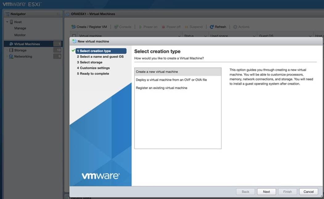
Step 2. Select Create a new virtual machine and click Next.
Step 3. Enter a name for the Virtual Machine and select the Compatibility, Guest OS family and Guest OS version as shown below:
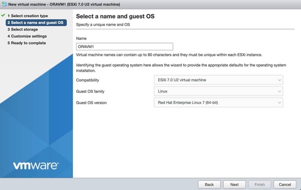
Step 4. Click Next and then for storage select ORAVM1-OS to install the RHEL OS onto the VMFS6 volume. Click Next to customize settings.
Step 5. Enter CPU, Memory and Hard Disk according to your environment.
Note: For this solution, we configured 48 CPU, 256GB memory, 300GB Hard Disk, three SCSI Controller and two Network Adapter to configure each VM.
Step 6. Select CD/DVD drive 1 option and from the CD/DVD Media menu, select RHEL 7.9 ISO to connect the RHEL ISO image to install the RHEL OS into the VM. Click Next and the click Finish to create the VM.
Step 7. Select Virtual Machine and right-click on option and select Power on. Open the VM Console and follow the remaining steps to install RHEL OS and configure the OS according to your environment.
Step 8. Apply hostname, configure network interfaces to configure all network interfaces.
Step 9. As a part of additional RPM package, we recommend selecting “Customize Now” option and relevant packages according to your environment.
Step 10. After the OS install finishes, reboot the VM and complete the appropriate registration steps. You can choose to synchronize the time with the NTP server. Alternatively, you can choose to use the Oracle RAC cluster synchronization daemon (OCSSD). Both NTP and OCSSD are mutually exclusive and OCSSD will be setup during GRID install if NTP is not configured.
This section describes the high-level steps to configure vCenter Server 7.0.
Procedure 1. Pure Storage vSphere Client Plugin
| Tech tip |
| The Pure Storage vSphere Client Plugin will be accessible through the vSphere Client after registration through the Pure Storage Web Portal. |
Step 1. Go to Settings > Software.
Step 2. Click the Edit icon in the vSphere Plugin panel. Enter the vCenter information and click Save.
Step 3. After the discovery completes, click install. In vCenter, click Pure Storage.
Step 4. Click Authenticate with Pure 1.
Step 5. Input your Pure1 JWT (link) and then Authenticate and then click Add.
Step 6. Click Import Arrays from Pure1 and input the Username and Password and click Done.
Step 7. Select the newly added array and then click Register Storage Provider. Enter the Username and Password and click Register.
Note: For this solution, we configured vCenter to manage all ESXi Hosts, shared datastore and networking. We configured “ORA-FlashStack” Datacenter and then created “ORA19C” Cluster to add all eight ESXi 7.0.2 Hosts as shown below:
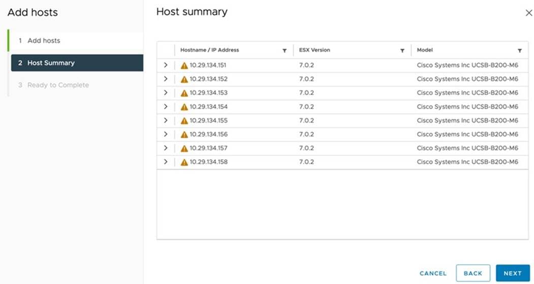
Note: Each ESXi Host has one RHEL VM configured to run as an Oracle RAC Database Node. As explained previously, for each Cisco UCS Blade Server, we configured total six vNICs. All the vNICs were configured in redundancy mode to distribute across both FI.
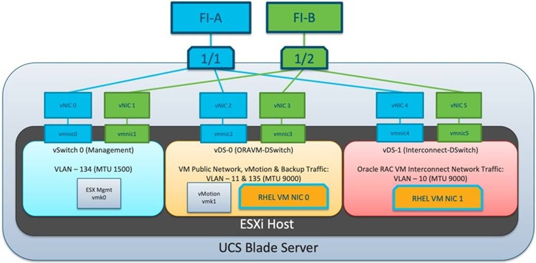
vSwitch 0 for Management Network
As shown in Figure 9, vNIC0 and vNIC1 were configured on VLAN 134 where vNIC0 was placed on FI-A and vNIC1 on FI-B. vmnic0 and vmnic1 were used to configure vSwitch0. vSwitch0 was configured with 1500 MTU and we added VMkernel Network Adapter as “IB-MGMT Network” with Active adapter as vmnic0 and vmnic1 to carry ESXi Management network traffic
DSwitches, Distributed, and Uplink Port Groups for vMotion and Application Traffic
vNIC2 and vNIC3 were configured on VLAN 11 and 135 where vNIC2 was placed on FI-A and vNIC3 on FI-B. vmnic2 and vmnic3 were used to configure virtual Distributed Switch0. vDS-0 (ORAVM-Switch) was configured with 9000 MTU and we added VMkernel Network Adapter for vMotion on VLAN 11. We configured Distributed Port Group as “VMkernel-vMotion” with VLAN ID 11 and kept failover order on uplink1 and uplink2 as ACTIVE/Standby. We also configured Distributed Port Group as “ORA-VM” with VLAN ID 135 and here kept failover order on uplink1 and uplink2 as ACTIVE/ACTIVE.
vNIC4 and vNIC5 were configured on VLAN 10 where vNIC4 was placed on FI-A and vNIC5 on FI-B. vmnic4 and vmnic5 were used to configure virtual Distributed Switch1. vDS-1 (Interconnect-DSwitch) was configured with 9000 MTU. We configured Distributed Port Group as “Interconnect” with VLAN ID 10 and kept failover order on uplink2 and uplink1 as ACTIVE/Standby. Notice that, to load balance Oracle RAC private interconnect traffic running on this NICs, we used uplink 2 as ACTIVE to navigate this traffic primarily through FI-B as we have vMotion and other management traffic running primarily on FI-A.
Also, the Uplink Port Group was created with VLAN trunk on both distributed switches.
ESXi Hosts and the vSwitch and vDS
After creating distributed switches, we added all ESXi Hosts into this vDS to configure two interfaces on RHEL VM as Public and Private Network Traffic for Oracle RAC Database nodes.
The Interconnect distributed port group is configured as shown below:
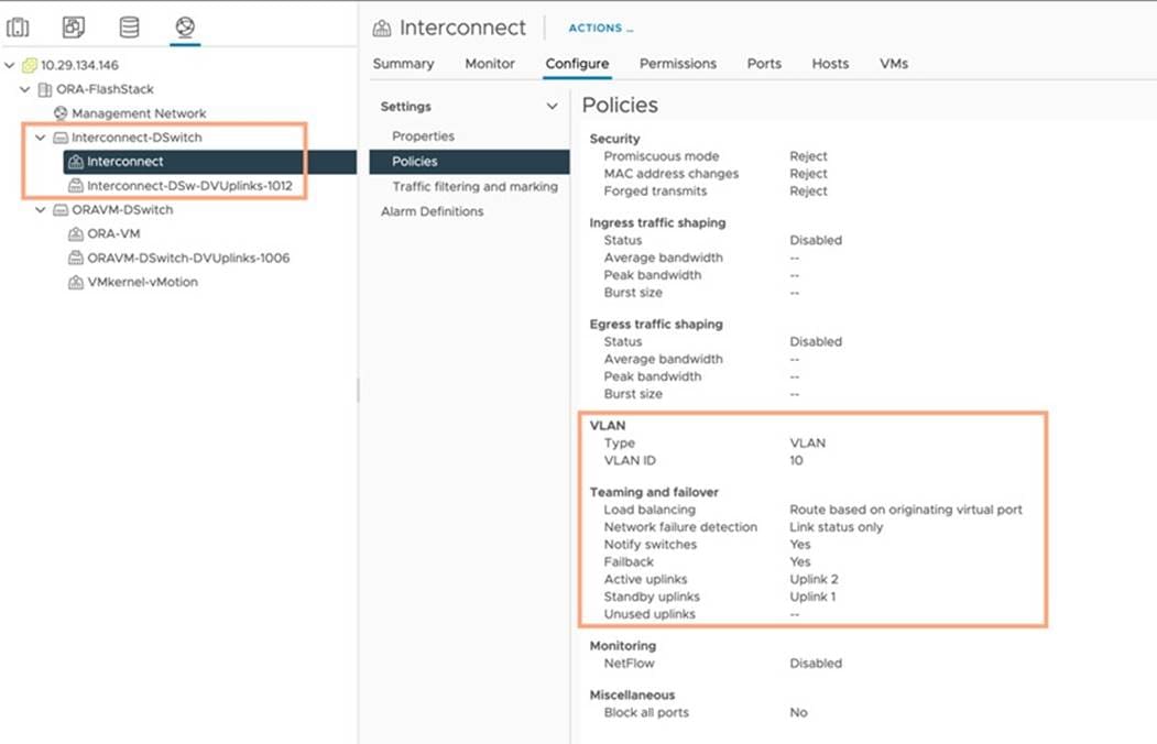
The ORA-VM distributed port group is configured as shown below:
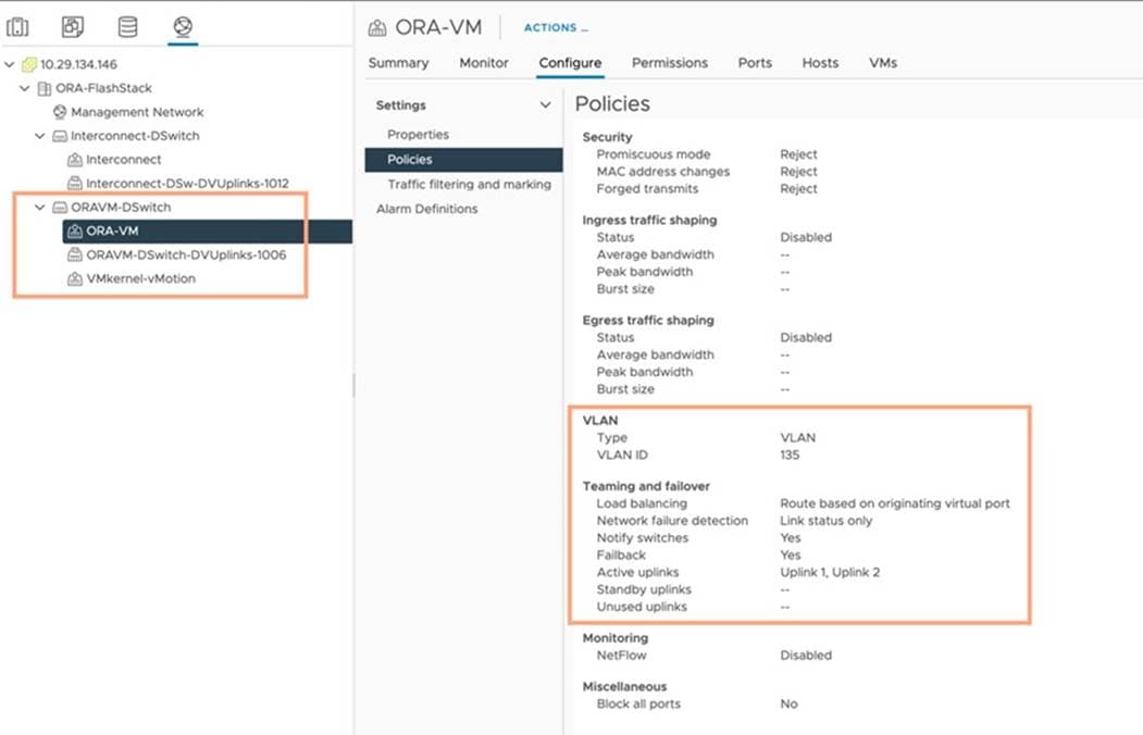
The VMkernel-vMotion distributed port group is configured as shown below:
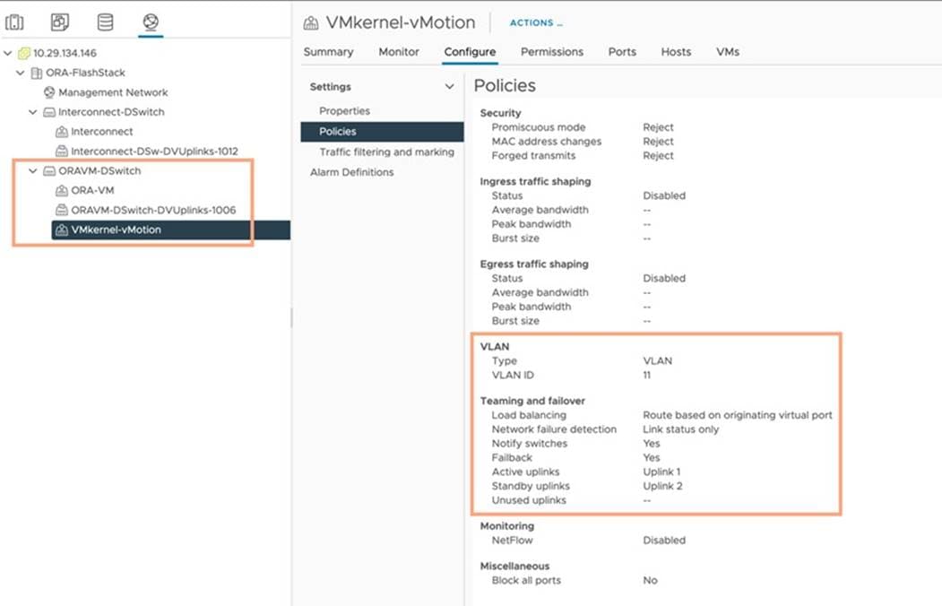
This completes the network configuration for this solution.
After adding vSphere Plugin, you can add the Pure Storage Array into vCenter Cluster.
Procedure 1. Add Pure Storage Array
Step 1. Enter the Array Name, Array URL, vCenter Username and Password to add the FlashArray into ORA19C Cluster. Click Submit.
Step 2. Go to the Storage tab and right- click Storage > Add New Datastore > Type as > vVol.
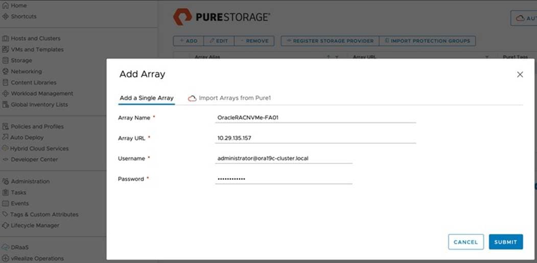
Note: We used “vvols” to deploy all Oracle RAC Databases on this FlashStack solution and kept the default storage policy “VVol No Requirements Policy” and mounted datastore to all ESXi Hosts a shown below:
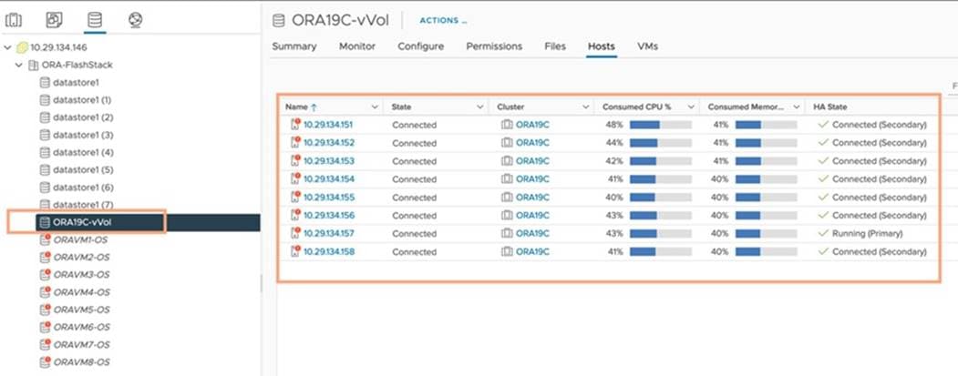
We configured all ESXi Hosts to run with High Performance Power as shown below:
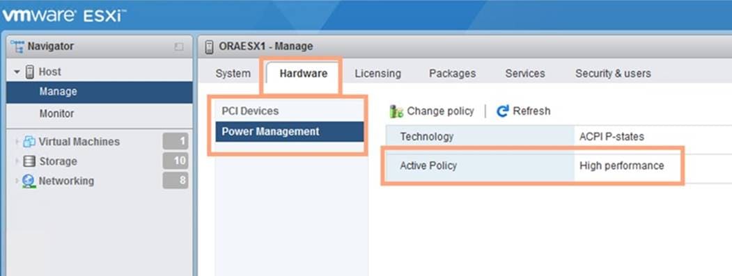
Configure VMware ENIC and FNIC Drivers for ESXi Hosts
For this solution, the VMware ENIC and FNIC Drivers were configured as follows:
● Cisco VIC VMware Network ESXi-7.0U2 ENIC Version: 1.0.35.0-1OEM.670.0.0.8169922 (Cisco_bootbank_nenic_1.0.35.0-1OEM.670.0.0.8169922.vib)
● Cisco VIC VMware Storage ESXi-7.0U2 FNIC Version: 4.0.0.71-1OEM.670.0.0.8169922 (Cisco_bootbank_nfnic_4.0.0.71-1OEM.670.0.0.8169922.vib)
Procedure 1. Install the VMware ENIC and FNIC ESXi Drivers
Step 1. Download the supported UCS Linux Drivers for UCS B-Series Blade Server Software for VMware from: https://software.cisco.com/download/home/283853163/type/283853158/release/4.2(1i)
Step 2. Check the current driver version by running the following commands:
[root@ORAESX1:~] esxcli software vib list |grep nenic
[root@ORAESX1:~] esxcli software vib list |grep nfnic
Step 3. Mount the Driver ISO file and go to Network and Storage folder to get Cisco VIC ENIC and FNIC driver for ESXi_7.0U2 . SCP those ENIC & FNIC driver to ESXi Host and SSH into the ESX Host.
Step 4. Install the supported VMware ENIC and FNIC drivers, by running the following commands:
[root@ORAESX1:~] esxcli software vib install -v /Cisco_bootbank_nfnic_4.0.0.71-1OEM.670.0.0.8169922.vib --no-sig-check
[root@ORAESX1:~] esxcli software vib install -v /Cisco_bootbank_nenic_1.0.35.0-1OEM.670.0.0.8169922.vib --no-sig-check
Step 5. Reboot the server and verify that the new driver is running:
[root@ORAESX1:~] esxcli software vib list |grep nfnic
nfnic 4.0.0.71-1OEM.670.0.0.8169922 Cisco VMwareCertified 2021-10-22
[root@ORAESX1:~] esxcli software vib list |grep nenic
nenic 1.0.35.0-1OEM.670.0.0.8169922 Cisco VMwareCertified 2021-09-22
Step 6. Repeat steps 1 - 5 and configure the VMware ENIC and FNIC drivers on all eight ESXi nodes.
| Tech tip |
| You should use a matching ENIC and FNIC pair. Check the Cisco UCS supported driver release for more information about the supported kernel version: https://www.cisco.com/c/en/us/support/docs/servers-unified-computing/ucs-manager/116349-technote-product-00.html |
Configure RHEL VM Public and Private Network Interfaces
If you have not configured the network interfaces during the VM RHEL OS installation, then configure them now. Each VM node must have at least two network interface or network adapters. One network interface is for the management public network traffic and the second interface is for the private network traffic (the node interconnects). The server nodes will access FC through vHBA.
Procedure 1. Configure Management Public and Private Network Interfaces
Step 1. Login as a root user into each VM RHEL node and go to /etc/sysconfig/network-scripts/.
Step 2. Configure the Public network and Private network IP addresses according to your environments.
| Tech tip |
| Configure the Private and Public network with the appropriate IP addresses on all eight VM RHEL Oracle RAC nodes. |
Configure RHEL OS Prerequisites for Oracle Software
To successfully install Oracle RAC Database 19c software, configure the operating system prerequisites on all eight VM nodes as explained in this section.
| Tech tip |
| Follow the steps according to your environment and requirements. For more information, see the Install and Upgrade Guide for Linux for Oracle Database 19C: https://docs.oracle.com/en/database/oracle/oracle-database/19/cwlin/configuring-operating-systems-for-oracle-grid-infrastructure-on-linux.html |
Procedure 1. Prerequisites RPM Installation
Step 1. To configure the operating system prerequisites using RPM for Oracle 19c software on all VM nodes, install the “oracle-database-preinstall-19c" rpm package. You can also download the required packages from: http://public-yum.oracle.com/oracle-linux-7.html.
Step 2. If you plan to use the “oracle-database-preinstall-19c" rpm package to perform all your prerequisites setup automatically, then login as root user and issue the following command on all the RAC nodes:
[root@orarac1 ~]# yum install oracle-database-preinstall-19c
| Tech tip |
| If you have not used the " oracle-database-preinstall-19c " package, then you will have to manually perform the prerequisites tasks on all the nodes. |
Additional Prerequisites Configuration
After configuring the automatic or manual prerequisites steps, you have a few additional steps to complete the prerequisites for the Oracle database software installations on all eight RHEL VM nodes as in this section.
Procedure 1. Disable SELinux
Since most organizations might already be running hardware-based firewalls to protect their corporate networks, you need to disabled Security Enhanced Linux (SELinux) and the firewalls at the server level for this reference architecture.
Step 1. Set the secure Linux to permissive by editing the "/etc/selinux/config" file, making sure the SELINUX flag is set as follows:
SELINUX=permissive
Procedure 2. Disable Firewall
Step 1. Check the status of the firewall by running following commands. (The status displays as active (running) or inactive (dead)). If the firewall is active / running, enter this command below to stop it:
systemctl status firewalld.service
systemctl stop firewalld.service
Step 2. To completely disable the firewalld service, so it does not reload when you restart the host machine, run the following command:
systemctl disable firewalld.service
Procedure 3. Disable Multipathing
Step 1. Check the status of the DM Multipath by running following commands. (The status displays as active (running) or inactive (dead)). If the DM Multipath is active / running, enter this command below to stop and disable it:
systemctl status multipathd.service
systemctl stop multipathd.service
Procedure 4. Create the Grid User
Step 1. Run this command to create a grid user:
useradd –u 54322 –g oinstall –G dba grid
Procedure 5. Set the User Passwords
Step 1. Run these commands to change the password for Oracle and Grid Users:
passwd oracle
passwd grid
Procedure 6. Configure /etc/hosts
Step 1. Login as a root user into the RHEL VM node and edit the “/etc/hosts” file.
Step 2. Provide the details for Public IP Address, Private IP Address, SCAN IP Address, and Virtual IP Address for all the nodes. Configure these settings in each Oracle RAC Nodes as shown below:
[root@oravm1 ~]# cat /etc/hosts
127.0.0.1 localhost localhost.localdomain localhost4 localhost4.localdomain4
### Public IP
10.29.135.171 oravm1 oravm1.ciscoucs.com
10.29.135.172 oravm2 oravm2.ciscoucs.com
10.29.135.173 oravm3 oravm3.ciscoucs.com
10.29.135.174 oravm4 oravm4.ciscoucs.com
10.29.135.175 oravm5 oravm5.ciscoucs.com
10.29.135.176 oravm6 oravm6.ciscoucs.com
10.29.135.177 oravm7 oravm7.ciscoucs.com
10.29.135.178 oravm8 oravm8.ciscoucs.com
### Virtual IP
10.29.135.179 oravm1-vip oravm1-vip.ciscoucs.com
10.29.135.180 oravm2-vip oravm2-vip.ciscoucs.com
10.29.135.181 oravm3-vip oravm3-vip.ciscoucs.com
10.29.135.182 oravm4-vip oravm4-vip.ciscoucs.com
10.29.135.183 oravm5-vip oravm5-vip.ciscoucs.com
10.29.135.184 oravm6-vip oravm6-vip.ciscoucs.com
10.29.135.185 oravm7-vip oravm7-vip.ciscoucs.com
10.29.135.186 oravm8-vip oravm8-vip.ciscoucs.com
### Private IP
10.10.10.171 oravm1-priv oravm1-priv.ciscoucs.com
10.10.10.172 oravm2-priv oravm2-priv.ciscoucs.com
10.10.10.173 oravm3-priv oravm3-priv.ciscoucs.com
10.10.10.174 oravm4-priv oravm4-priv.ciscoucs.com
10.10.10.175 oravm5-priv oravm5-priv.ciscoucs.com
10.10.10.176 oravm6-priv oravm6-priv.ciscoucs.com
10.10.10.177 oravm7-priv oravm7-priv.ciscoucs.com
10.10.10.178 oravm8-priv oravm8-priv.ciscoucs.com
### SCAN IP
10.29.135.189 oravm-scan oravm-scan.ciscoucs.com
10.29.135.190 oravm-scan oravm-scan.ciscoucs.com
10.29.135.191 oravm-scan oravm-scan.ciscoucs.com
Step 3. You must configure the following addresses manually in your corporate setup:
● A Public and Private IP Address for each RHEL VM node
● A Virtual IP address for each RHEL VM node
● Three single client access name (SCAN) address for the oracle database cluster
Note: All the steps above were performed on all of the eight RHEL VM nodes. These steps complete the prerequisite for Oracle Database 19c Installation at OS level on Oracle RAC Nodes.
Procedure 7. Configure UDEV Rules for IO Policy
You need to configure the UDEV rules to assign IO Policy in all ESXi Hosts to access the Pure Storage volumes in a round-robin pattern. You also need to change the device property. The steps must be performed on all ESX Hosts.
Step 1. Login as root user into ESX Host and find the nmp device list by following command.
[root@ORAVM2:~] esxcli storage nmp device list -d naa.624a93701c0d5dfa58fa45d800011952
naa.624a93701c0d5dfa58fa45d800011952
Device Display Name: PURE Fibre Channel Disk (naa.624a93701c0d5dfa58fa45d800011952)
Storage Array Type: VMW_SATP_ALUA
Storage Array Type Device Config: {implicit_support=on; explicit_support=off; explicit_allow=on; alua_followover=on; action_OnRetryErrors=off; {TPG_id=1,TPG_state=AO}{TPG_id=0,TPG_state=AO}}
Path Selection Policy: VMW_PSP_RR
Path Selection Policy Device Config: {policy=latency,latencyEvalTime=180000,samplingCycles=16,curSamplingCycle=16,useANO=0; CurrentPath=vmhba2:C0:T5:L248: NumIOsPending=0,latency=0}
Path Selection Policy Device Custom Config:
Working Paths: vmhba2:C0:T5:L248, vmhba3:C0:T9:L248, vmhba2:C0:T8:L248, vmhba3:C0:T12:L248, vmhba3:C0:T11:L248, vmhba2:C0:T7:L248, vmhba2:C0:T6:L248, vmhba3:C0:T10:L248
Is USB: false
Step 2. Change the device property by running the following command:
[root@ORAVM2:~] esxcli storage nmp psp roundrobin deviceconfig set --type=iops --iops=1 --device= naa.624a93701c0d5dfa58fa45d800011952;
Step 3. Verify the device property by running the following commands:
[root@ORAVM2:~] esxcli storage nmp device list -d naa.624a93701c0d5dfa58fa45d800011952
naa.624a93701c0d5dfa58fa45d800011952
Device Display Name: PURE Fibre Channel Disk (naa.624a93701c0d5dfa58fa45d800011952)
Storage Array Type: VMW_SATP_ALUA
Storage Array Type Device Config: {implicit_support=on; explicit_support=off; explicit_allow=on; alua_followover=on; action_OnRetryErrors=off; {TPG_id=1,TPG_state=AO}{TPG_id=0,TPG_state=AO}}
Path Selection Policy: VMW_PSP_RR
Path Selection Policy Device Config: {policy=iops,iops=1,bytes=10485760,useANO=0; lastPathIndex=3: NumIOsPending=0,numBytesPending=0}
Path Selection Policy Device Custom Config: policy=iops;iops=1;bytes=10485760;samplingCycles=16;latencyEvalTime=180000;useANO=0;
Working Paths: vmhba2:C0:T5:L248, vmhba3:C0:T9:L248, vmhba2:C0:T8:L248, vmhba3:C0:T12:L248, vmhba3:C0:T11:L248, vmhba2:C0:T7:L248, vmhba2:C0:T6:L248, vmhba3:C0:T10:L248
Is USB: false
Step 4. When all the OS level prerequisites are configured, install the Oracle Grid Infrastructure as a grid user. Download Oracle Database 19c Release (19.3) for Linux x86-64 and Oracle Database 19c Release Grid Infrastructure (19.3) for Linux x86-64 software from Oracle Software site. Copy these software binaries to first RHEL VM Oracle RAC Node 1 and Unzip all files into appropriate directories.
Note: These steps complete the prerequisite for the Oracle Database 19c Installation at OS level on the Oracle RAC Nodes.
Oracle Database 19c GRID Infrastructure Deployment
This section describes the high-level steps for the Oracle Database 19c RAC installation. This document provides a partial summary of details that might be relevant.
Note: It is not within the scope of this document to include the specifics of an Oracle RAC installation; you should refer to the Oracle installation documentation for specific installation instructions for your environment. For more information, use this link for Oracle Database 19c install and upgrade guide: https://docs.oracle.com/en/database/oracle/oracle-database/19/cwlin/index.html
Install the Oracle Grid and Database software on all eight RHEL VM nodes (ORAVM1 to ORAVM8).
Note: For this solution, we created one vVOL of 100 GB in size and shared across all eight RHEL VMs for storing OCR and Voting Disk files for all RAC databases as shown in below:
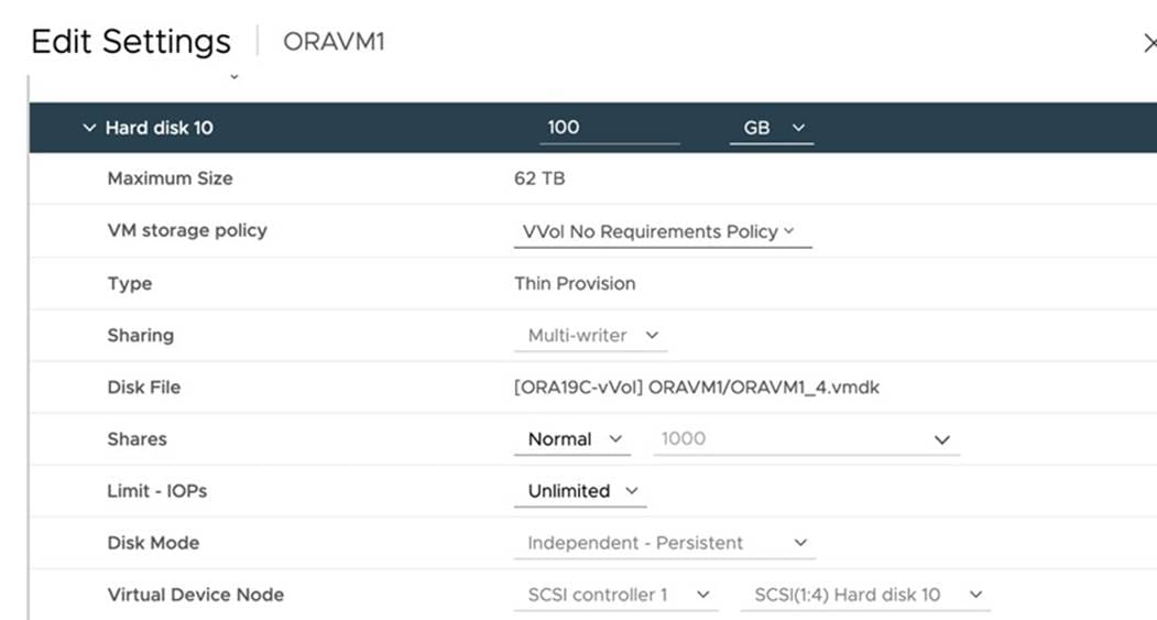
Oracle 19c Release 19.3 Grid Infrastructure (GI) was installed on the first node as a grid user. The installation also configured and added the remaining seven nodes as a part of the GI setup. The Oracle Automatic Storage Management (ASM) in Flex mode was configured. Complete the following procedure to install the Oracle Grid Infrastructure software for the Oracle Standalone Cluster.
Procedure 1. Create Directory Structure
Step 1. Download and copy the Oracle Grid Infrastructure image files to the local node only. During installation, the software is copied and installed on all other nodes in the cluster.
Step 2. Create the directory structure according to your environment and run the following commands:
For example:
mkdir -p /u01/app/grid
mkdir -p /u01/app/19.3.0/grid
mkdir -p /u01/app/oraInventory
mkdir -p /u01/app/oracle/product/19.3.0/dbhome_1
chown -R grid:oinstall /u01/app/grid
chown -R grid:oinstall /u01/app/19.3.0/grid
chown -R grid:oinstall /u01/app/oraInventory
chown -R oracle:oinstall /u01/app/oracle
Step 3. As the grid user, download the Oracle Grid Infrastructure image files and extract the files into the Grid home:
cd /u01/app/19.0.0/grid
unzip -q download_location/grid.zip
Procedure 2. Configure UDEV rules for ASM Disks
You need to configure UDEV rules to have read/write privileges on these storage volumes for grid user. This includes the device details and corresponding scsi id of the storage volumes. You also need to configure the UDEV rules on all RHEL VM Oracle RAC Nodes.
Step 1. Assign IO Policy by creating a new file named “99-oracleasm.rules” with the following entries on all the RHEL VM nodes:
[root@oravm1 ~]# cat /etc/udev/rules.d/99-oracleasm.rules
KERNEL=="sd*1", SUBSYSTEM=="block", PROGRAM=="/usr/lib/udev/scsi_id -g -u -d /dev/$parent", RESULT=="36000c2979bbca372f07b1b332fe034c0", SYMLINK+="asm-disk1" ,OWNER="grid", GROUP="oinstall", MODE="0660"
Note: You will edit this file later as you add more vvols for “DATA” and “REDO” disk group volumes for Oracle RAC Databases.
Procedure 3. Run Cluster Verification Utility
This step verifies that all the prerequisites are met to install the Oracle Grid Infrastructure Software. Oracle Grid Infrastructure ships with the Cluster Verification Utility (CVU) that can run to validate the pre and post installation configurations.
Step 1. Login as Grid User in Oracle RAC Node 1 and go to the directory where Oracle Grid software binaries are located. Run the script named “runcluvfy.sh” as follows:
./runcluvfy.sh stage -pre crsinst -n oravm1,oravm2,oravm3,oravm4,oravm5,oravm6,oravm7,oravm8 –verbose
Procedure 4. Configure HugePages
HugePages is a method to have a larger page size that is useful for working with a very large memory. For Oracle Databases, using HugePages reduces the operating system maintenance of page states, and increases Translation Lookaside Buffer (TLB) hit ratio.
Advantage of HugePages:
● HugePages are not swappable so there is no page-in/page-out mechanism overhead.
● HugePages uses fewer pages to cover the physical address space, so the size of "bookkeeping"(mapping from the virtual to the physical address) decreases, so it is requiring fewer entries in the TLB and so TLB hit ratio improves.
● HugePages reduces page table overhead. Also, HugePages eliminated page table lookup overhead: Since the pages are not subject to replacement, page table lookups are not required.
● Faster overall memory performance: On virtual memory systems each memory operation is two abstract memory operations. Since there are fewer pages to work on, the possible bottleneck on page table access is clearly avoided.
Note: For our configuration, we used HugePages for all the OLTP and DSS workloads. Please refer to the Oracle guidelines to configure HugePages: https://docs.oracle.com/en/database/oracle/oracle-database/19/unxar/administering-oracle-database-on-linux.html#GUID-CC72CEDC-58AA-4065-AC7D-FD4735E14416
After configuration, you are ready to install the Oracle Grid Infrastructure and Oracle Database 19c software.
Note: For this solution, we installed Oracle home binaries on the boot volume of the nodes. The OCR, Data, and Redo Log files reside in the vvols configured on Pure Storage array through vCenter Cluster.
Procedure 5. Install and Configure Oracle Database Grid Infrastructure Software
Note: It is not within the scope of this document to include the specifics of an Oracle RAC installation. However, a partial summary of details is provided that might be relevant. Please refer to the Oracle installation documentation for specific installation instructions for your environment.
Step 2. Go to grid home where the Oracle 19c Grid Infrastructure software binaries are located and launch the installer as the "grid" user.
Step 3. Start the Oracle Grid Infrastructure installer by running the following command:
./gridSetup.sh
Step 4. Select the option “Configure Oracle Grid Infrastructure for a New Cluster”, then click Next.
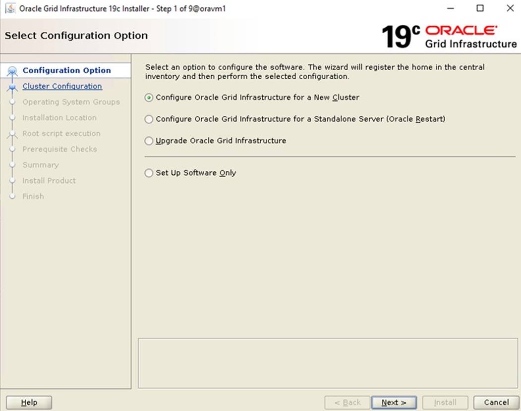
Step 5. Select cluster configuration options “Configure an Oracle Standalone Cluster”, then click Next.
Step 6. In next window, enter the Cluster Name and SCAN Name fields. Enter the names for your cluster and cluster scan that are unique throughout your entire enterprise network. You can also select to Configure GNS if you have configured your domain name server (DNS) to send to the GNS virtual IP address name resolution requests.
Step 7. In Cluster node information window, click the "Add" button to add all the eight nodes Public Hostname and Virtual Hostname as shown below:
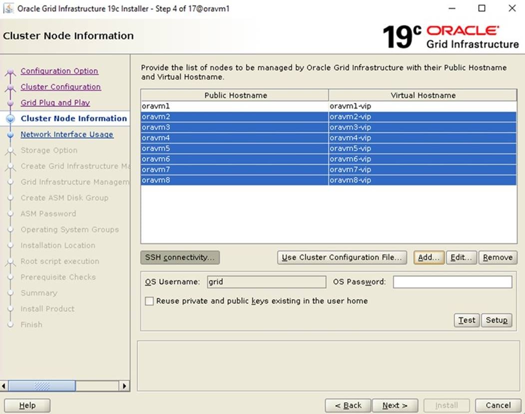
Step 8. As shown above, you will see all nodes listed in the table of cluster nodes. Click the SSH Connectivity button at the bottom of the window. Enter the operating system username and password for the Oracle software owner (grid). Click Setup.
Step 9. A message window appears, indicating that it might take several minutes to configure SSH connectivity between the nodes. After some time, another message window appears indicating that password-less SSH connectivity has been established between the cluster nodes. Click OK to continue
Step 10. In Network Interface Usage screen, select the usage type for each network interface for Public and Private Network Traffic and click Next.
Step 11. In the storage option, select the option \ “Use Oracle Flex ASM for storage” then click Next.
Note: For this solution we chose the “No” option into separate ASM disk group for the Grid Infrastructure Management Repository data.
Step 12. In the Create ASM Disk Group window, select the shared vVol disks configured earlier into the vVOL datastore into Pure Storage to store OCR and Voting disk files. For the disk group name, enter “OCRVOTE” and select the appropriate external redundancy options as shown below:
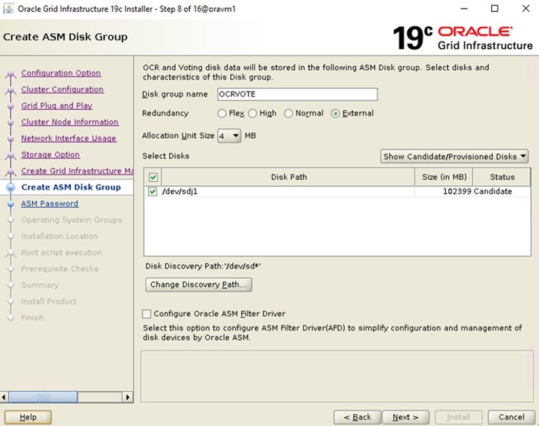
Note: For this solution, we did not configure the Oracle ASM Filter Driver.
Step 13. Choose the password for the Oracle ASM SYS and ASMSNMP account, then click Next.
Step 14. Select the option “Do not use Intelligent Platform Management Interface (IPMI).” Click Next.
| Tech tip |
| You can configure to have this instance of the Oracle Grid Infrastructure and Oracle Automatic Storage Management to be managed by Enterprise Manager Cloud Control. For this solution we did not select this option. You can choose to set it up according to your requirements. |
Step 15. Click Next.
Step 16. Select the appropriate operating system group names for Oracle ASM according to your environments.
Step 17. Specify the oracle base and inventory directory to use for the Oracle Grid Infrastructure installation and then click Next. The Oracle base directory must be different from the Oracle home directory. Click Next and select the Inventory Directory according to your setup.
Step 18. Click Automatically run configuration scripts to run scripts automatically and enter the relevant root user credentials. Click Next.
Step 19. Wait while the prerequisite checks complete. If you have any issues, click the "Fix & Check Again" button. If any of the checks have a status of Failed and are not fixable, then you must manually correct these issues. After you have fixed the issue, you can click the Check Again button to have the installer re-check the requirement and update the status. Repeat as needed until all the checks have a status of Succeeded. Click Next.
Step 20. Review the contents of the Summary window and then click Install. The installer displays a progress indicator enabling you to monitor the installation process.
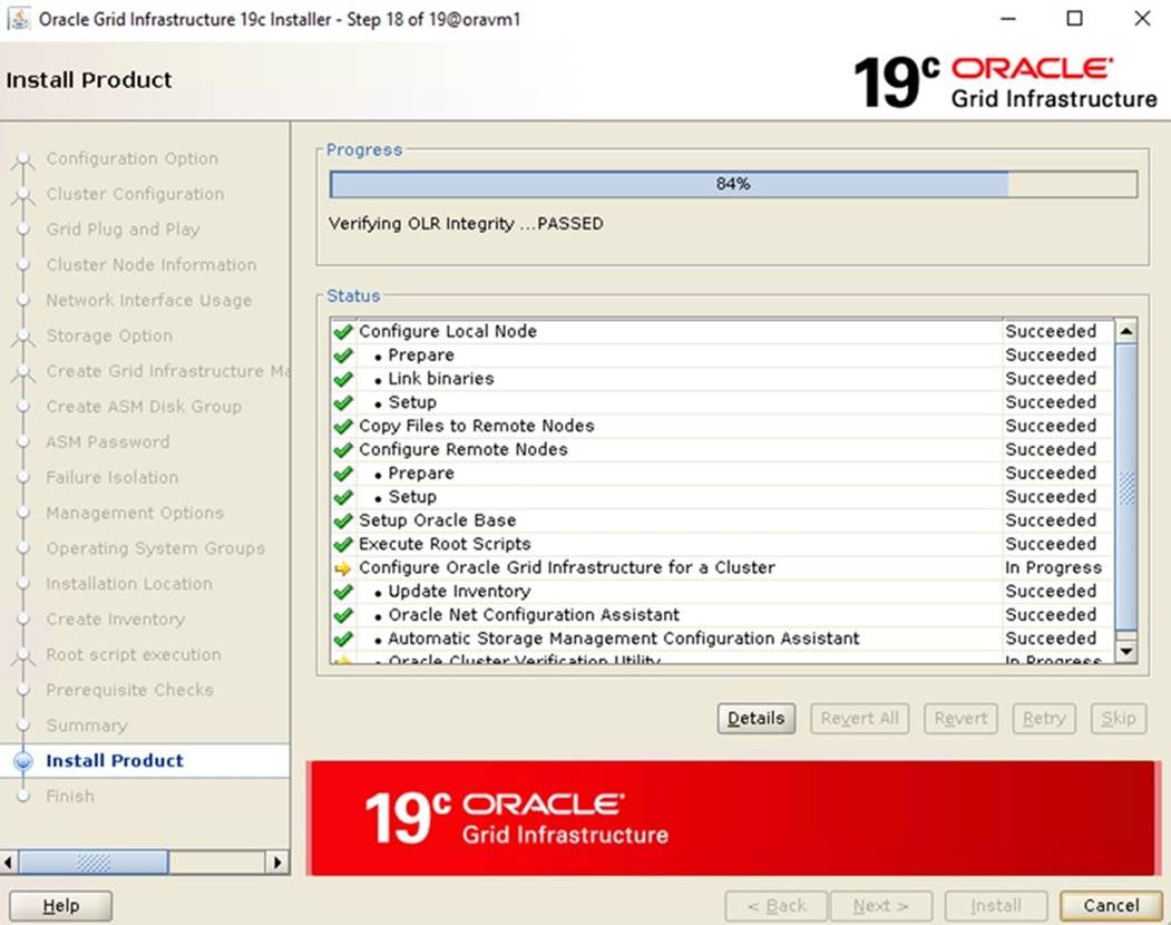
Step 21. Wait for the grid installer configuration assistants to complete. When the configuration completes successfully, click Close to finish and exit the grid installer.
Step 22. When GRID install is successful, login to each of the nodes and perform the minimum health checks to make sure that the Cluster state is healthy. After your Oracle Grid Infrastructure installation is complete, you can install Oracle Database on a cluster node for high availability or install Oracle RAC.
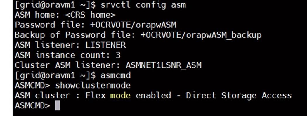
| Tech tip |
| After successfully installing the Oracle GRID, it’s recommended to install the Oracle Database 19c software only. You can create databases using DBCA or database creation scripts at later stage. |
It is not within the scope of this document to include the specifics of an Oracle RAC database installation. However, a partial summary of details is provided that might be relevant. Please refer to the Oracle database installation documentation for specific installation instructions for your environment here: https://docs.oracle.com/en/database/oracle/oracle-database/19/ladbi/index.html.
Procedure 1. Install Oracle Database Software
Step 1. Start the ./runInstaller command from the Oracle Database 19c installation media where the Oracle database software is located.
Step 2. Select the option “Set Up Software Only” into configuration Option.
Step 3. Select the option "Oracle Real Application Clusters database installation" and click Next.
Step 4. Select the nodes in the cluster where the installer should install Oracle RAC. For this setup, install the software on all eight nodes as shown below:
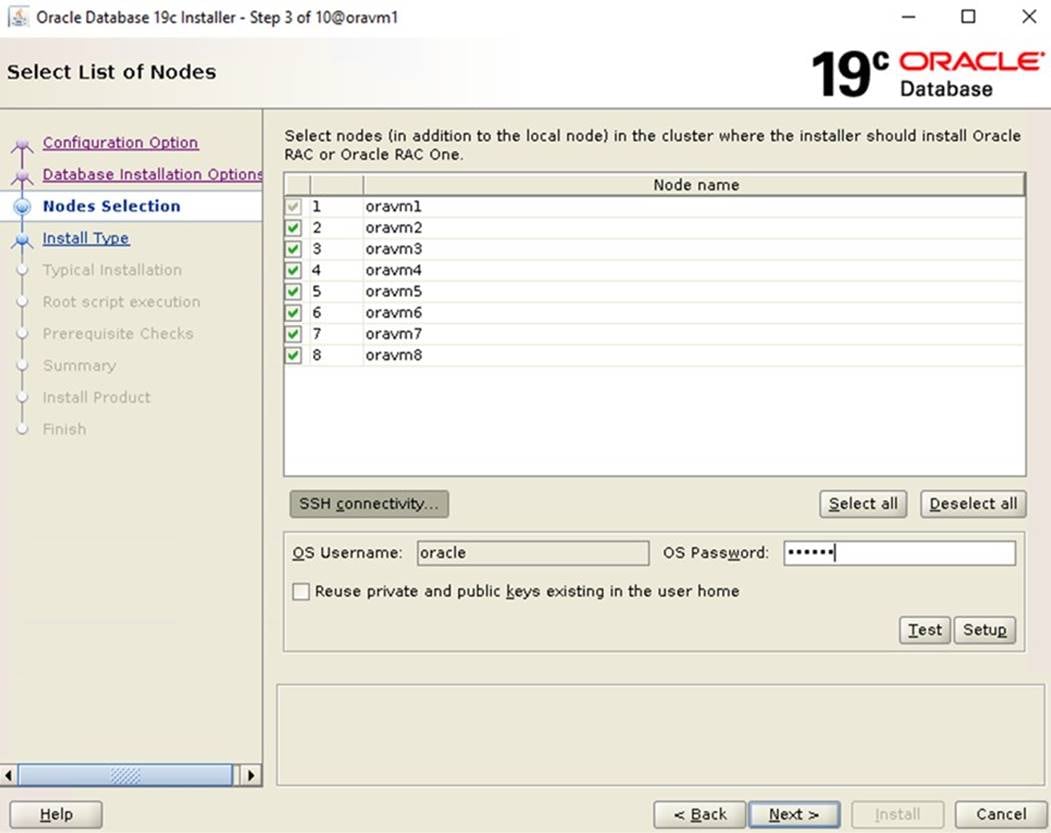
Step 5. Click "SSH Connectivity..." and enter the password for the "oracle" user. Click Setup to configure passwordless SSH connectivity and click Test to test it when it is complete. When the test is complete, click Next.
Step 6. Select the Database Edition Options according to your environments and then click Next.
Step 7. Enter the appropriate Oracle Base, then click Next.
Step 8. Select the desired operating system groups and then click Next.
Step 9. Select the option Automatically run configuration script from the option Root script execution menu and click Next.
Step 10. Wait for the prerequisite check to complete. If there are any problems, click "Fix & Check Again" or try to fix those by checking and manually installing required packages. Click Next.
Step 11. Verify the Oracle Database summary information and then click Install.
Step 12. Wait for the installation of Oracle Database finish successfully, then click Close to exit of the installer.
Note: These steps complete the installation of the Oracle Grid and Oracle Database software. We upgraded and applied the patch for the Grid Infrastructure and the database software version to 19.12.
Oracle ASM is Oracle's recommended storage management solution that provides an alternative to conventional volume managers, file systems, and raw devices. Oracle ASM is a volume manager and a file system for Oracle Database files that reduces the administrative overhead for managing database storage by consolidating data storage into a small number of disk groups. The smaller number of disk groups consolidates the storage for multiple databases and provides for improved I/O performance.
Oracle Flex ASM enables an Oracle ASM instance to run on a separate physical server from the database servers. With this deployment, larger clusters of Oracle ASM instances can support more database clients while reducing the Oracle ASM footprint for the overall system.
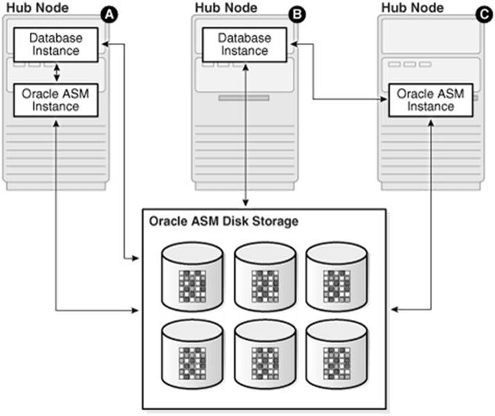
When using Oracle Flex ASM, Oracle ASM clients are configured with direct access to storage. With Oracle Flex ASM, you can consolidate all the storage requirements into a single set of disk groups. All these disk groups are mounted by and managed by a small set of Oracle ASM instances running in a single cluster. You can specify the number of Oracle ASM instances with a cardinality setting. The default is three instances.
Prior to Oracle 12c, if ASM instance on one of the RAC nodes crashes, all the instances running on that node will crash too. This issue has been addressed in Flex ASM; Flex ASM can be used even if all the nodes are hub nodes. However, GNS configuration is mandatory for enabling Flex ASM. You can check what instances relate to a simple query as shown below:
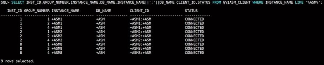
As you can see from the query (above), instance1, instance2 and instance8 are connected to +ASM. There are a few more commands you can run to check the cluster and FLEX ASM details as shown below:
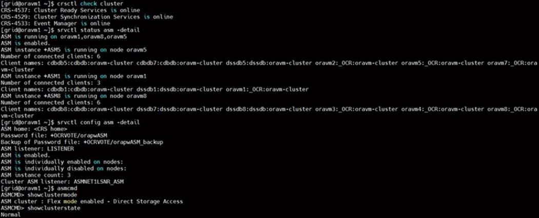
Refer to the Oracle documentation for more information: https://docs.oracle.com/en/database/oracle/oracle-database/19/ostmg/manage-flex-asm.html#GUID-DE759521-9CF3-45D9-9123-7159C9ED4D30
Oracle Database Multitenant Architecture
The multitenant architecture enables an Oracle database to function as a multitenant container database (CDB). A CDB includes zero, one, or many customer-created pluggable databases (PDBs). A PDB is a portable collection of schemas, schema objects, and non-schema objects that appears to an Oracle Net client as a non-CDB. All Oracle databases before Oracle Database 12c were non-CDBs.
A container is logical collection of data or metadata within the multitenant architecture. The following figure represents possible containers in a CDB.
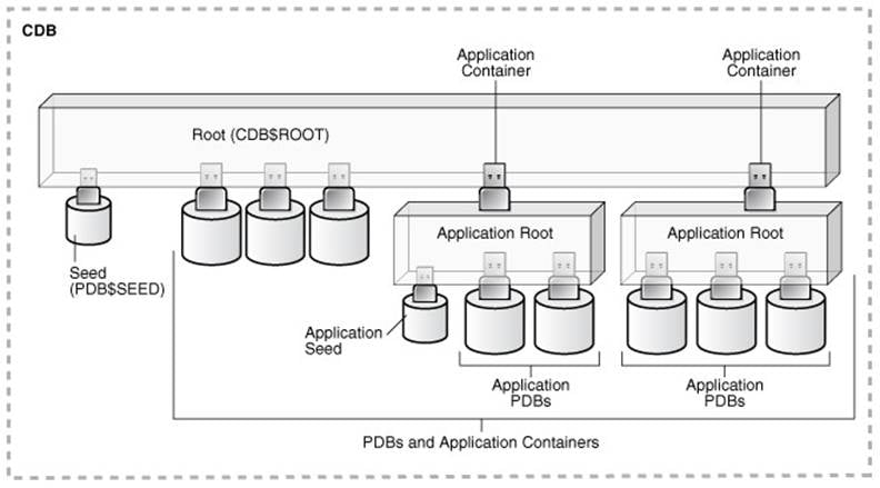
The multitenant architecture solves several problems posed by the traditional non-CDB architecture. Large enterprises may use hundreds or thousands of databases. Often these databases run on different platforms on multiple physical servers. Because of improvements in hardware technology, especially the increase in the number of CPUs, servers can handle heavier workloads than before. A database may use only a fraction of the server hardware capacity. This approach wastes both hardware and human resources. Database consolidation is the process of consolidating data from multiple databases into one database on one computer. The Oracle Multitenant option enables you to consolidate data and code without altering existing schemas or applications.
For more information on Oracle Database Multitenant Architecture, go to: https://docs.oracle.com/en/database/oracle/oracle-database/19/multi/introduction-to-the-multitenant-architecture.html#GUID-267F7D12-D33F-4AC9-AA45-E9CD671B6F22
Note: In this solution, we configured both type of databases to check performance of Non-Container Databases and Container Databases as explained in section Scalability Test and Results.
This chapter is organized into the following subjects:
| Chapter |
Subjects |
| Scalability Test Results |
Before configuring a database for workload tests, it is extremely important to validate that this is indeed a balanced configuration that is capable of delivering expected performance. In this solution, we will test and validate node and user scalability on all 8 node Oracle RAC Databases with various database benchmarking tools as explained below.
Hardware Calibration Test using FIO
Flexible IO (FIO) is a versatile IO workload generator. FIO is a tool that will spawn a number of threads or processes doing a particular type of I/O action as specified by the user.
For our solution, we used FIO to measure the performance of a storage vvols volumes over a given period. For the FIO Tests, we created eight vvols (each vVol of 1 TB in size) and these eight vvols were configured as “multi-writer” and shared across all the eight RHEL VM nodes for read/write IO operations as shown below:
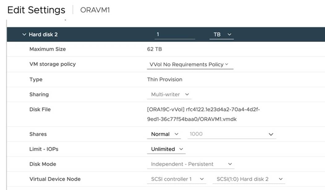
We ran various FIO tests for measuring IOPS, Latency and Throughput performance of this solution by changing block size parameter into the FIO test. For each FIO test, we also changed the read/write ratio as 0/100 % read/write, 50/50 % read/write, 70/30 % read/write, 90/10 % read/write and 100/0 % read/write to scale the performance of the system. We also ran the tests for at least 4 hours to help ensure that this configuration is capable of sustaining this type of load for longer period of time.
The chart below shows the results for the random read/write FIO test for the 8k block size representing OLTP type of workloads:
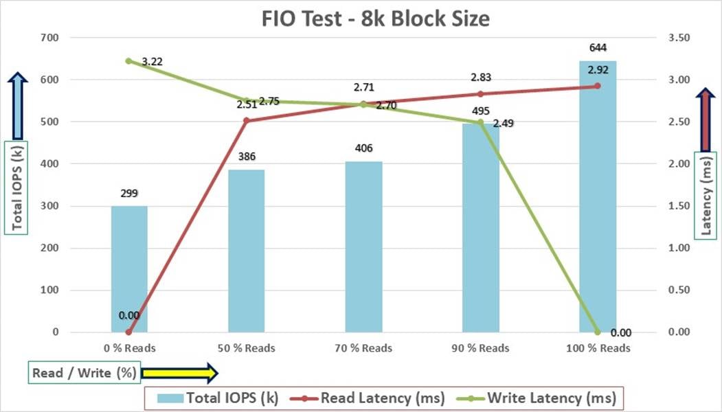
For the 100/0 % read/write test, we achieved around 644k IOPS with the read latency around 2.9 millisecond. Similarly, for the 90/10 % read/write test, we achieved around 495k IOPS with the read latency around 2.8 millisecond and the write latency around 2.4 millisecond. For the 70/30 % read/write test, we achieved around 406k IOPS with the read and write latency around 2.7 millisecond. For the 50/50 % read/write test, we achieved around 386k IOPS with the read latency around 2.5 millisecond and the write latency around 2.7 millisecond. For the 0/100 % read/write test, we achieved around 299k IOPS with the write latency around 3.2 millisecond. Reads and writes consume system resources differently.
The bandwidth tests are carried out with 512k IO Size and represents the DSS database type workloads. The chart below shows results for the sequential read/write FIO test for the 512k block size:
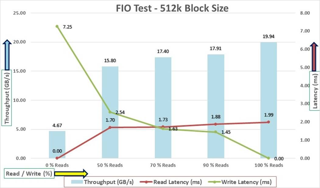
For the 100/0 % read/write test, we achieved around 19.9 GB/s throughput with the read latency around 1.9 millisecond. Similarly, for the 90/10 % read/write test, we achieved around 17.9 GB/s throughput with the read latency around 1.8 millisecond and the write latency around 1.4 millisecond. For the 70/30 % read/write test, we achieved around 17.4 GB/s throughput with the read latency around 1.7 millisecond and the write latency around 1.6 millisecond. For the 50/50 % read/write test, we achieved around 15.8 GB/s throughput with the read latency around 1.7 millisecond and the write latency around 2.5 millisecond. For the 0/100 % read/write test, we achieved around 4.6 GB/s throughput with the write latency around 7.2 millisecond.
We did not see any performance dips or degradation over the period of run time. It is also important to note that this is not a benchmarking exercise, and these are practical and out-of-box test numbers that can be easily reproduced by anyone. At this time, we are ready to create OLTP database(s) and continue with database tests.
We used Oracle Database Configuration Assistant (DBCA) to create three OLTP (SLOB, PDBSOE and PDBFIN) and one DSS (PDBSH) databases for SLOB and SwingBench test calibration. For each databases, we created two disk groups “data” and “redolog” to store the database files. We configured 8 multi-writer shared vvols to create Oracle ASM “Data” disk group and 4 multi-writer shared vvols to create Oracle ASM “redolog” disk group and shared across two SCSI controller on each VMs. We used the widely adopted SLOB and SwingBench database performance test tools to test and validate throughput, IOPS, and latency for various test scenarios as explained below.
The Silly Little Oracle Benchmark (SLOB) is a toolkit for generating and testing I/O through an Oracle database. SLOB is very effective in testing the I/O subsystem with genuine Oracle SGA-buffered physical I/O. SLOB supports testing physical random single-block reads (db file sequential read) and random single block writes (DBWR flushing capability). SLOB issues single block reads for the read workload that are generally 8K (as the database block size was 8K).
For testing the SLOB workload, we created one non-container database as SLOB. For SLOB database, we created a total of 12 shared vvols. On these 12 vvols, we created two disk groups to store the “data” and “redolog” files for the SLOB database. The first disk-group “DATASLOB” was created with 8 vvols (1 TB each) while second disk-group “REDOSLOB” was created with 4 vvols (100 GB each).
Those ASM disk groups provided the storage required to create the tablespaces for the SLOB Database. We loaded the SLOB schema on “DATASLOB” disk-group of up to 3.5 TB in size.
We used SLOB2 to generate our OLTP workload. Each database server applied the workload to Oracle database, log, and temp files. The following tests were performed and various metrics like IOPS and latency were captured along with Oracle AWR reports for each test scenario.
SLOB2 was configured to run against all the eight Oracle RAC nodes and the concurrent users were equally spread across all the nodes. We tested the environment by increasing the number of Oracle users in database from a minimum of 64 users up to a maximum of 512 users across all the nodes. At each load point, we verified that the storage system and the server nodes could maintain steady-state behavior without any issues. We also made sure that there were no bottlenecks across servers or networking systems.
The User Scalability test was performed with 64, 128, 192, 256, 384 and 512 users on 8 Oracle RAC nodes by varying read/write ratio as explained below:
● Varying workloads
◦ 100% read (0% update)
◦ 90% read (10% update)
◦ 70% read (30% update)
◦ 50% read (50% update)
Table 12 lists the total number of IOPS (both read and write) available for user scalability test when run with 64, 128, 192, 256, 384 and 512 Users on the SLOB database.
Table 12. Total IOPS for SLOB User Scalability Tests
| Users |
Read/Write % (100-0) |
Read/Write % (90-10) |
Read/Write % (70-30) |
Read/Write % (50-50) |
| 64 |
176,567 |
180,789 |
192,878 |
203,459 |
| 128 |
336,735 |
317,965 |
316,539 |
322,474 |
| 192 |
463,721 |
409,398 |
388,978 |
390,293 |
| 256 |
572,337 |
451,440 |
430,882 |
412,087 |
| 384 |
577,507 |
488,547 |
424,170 |
420,956 |
| 512 |
599,778 |
494,974 |
409,036 |
423,887 |
The following graphs demonstrate the total number of IOPS while running SLOB workload for various concurrent users for each test scenario.
The graph below shows the linear scalability with increased users and similar IOPS from 64 users to 512 users with 100% Read/Write, 90% Read/Write, 70% Read/Write and 50% Read/Write.
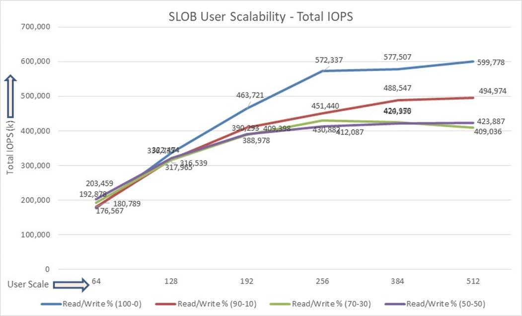
The AWR screenshot shown below was captured from a 100% Read (0% update) Test scenario while running SLOB test for 512 users for 12 Hours. The screenshot shows a section from the Oracle AWR report from the run that highlights Physical Reads/Sec and Physical Writes/Sec for each instance.
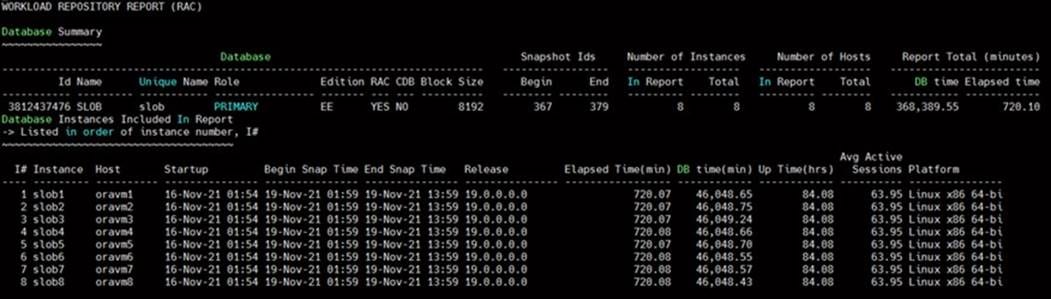
The screenshot below highlights that IO load is distributed across all the cluster nodes performing workload operations. Due to variations in workload randomness, we conducted multiple runs to ensure consistency in behavior and test results.
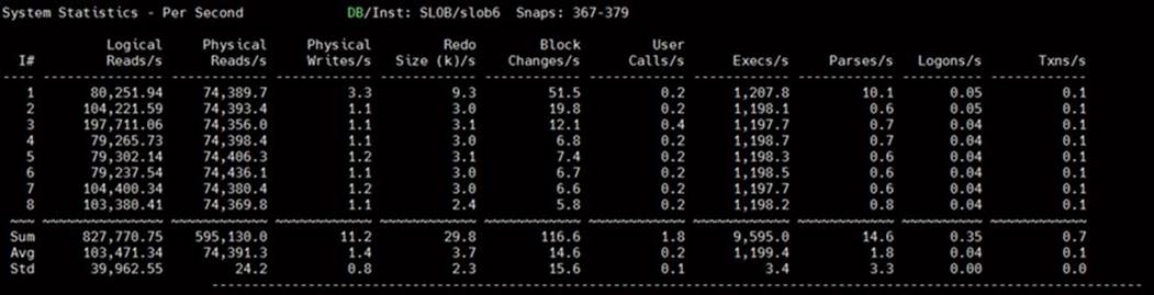
The following graph illustrates the latency exhibited by the Pure Storage //X90R3 FlashArray across different workloads. All the workloads experienced less than 2 millisecond latency and it varies based on the workloads. As expected, the 50% read (50% update) test exhibited higher latencies as the user counts increases.
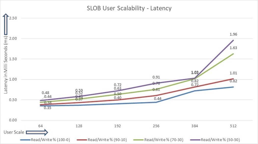
The following screenshot was captured from 100 % Read (0% Update) Test scenario while running SLOB test for 512 users. The snapshot shows a section of AWR report from the run that highlights top timed Events.
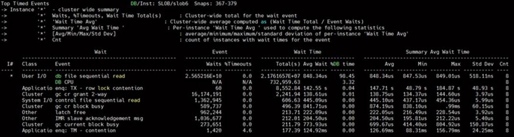
SwingBench is a simple to use, free, Java-based tool to generate various types of database workloads and perform stress testing using different benchmarks in Oracle database environments. SwingBench can be used to demonstrate and test technologies such as Real Application Clusters, Online table rebuilds, Standby databases, online backup, and recovery, and so on. In this solution, we used SwingBench tool for running various type of workload and check the overall performance of this reference architecture.
SwingBench provides four separate benchmarks, namely, Order Entry, Sales History, Calling Circle, and Stress Test. For the tests described in this solution, SwingBench Order Entry (SOE) benchmark was used for representing OLTP type of workload and the Sales History (SH) benchmark was used for representing DSS type of workload.
The Order Entry benchmark is based on SOE schema and is TPC-C like by types of transactions. The workload uses a very balanced read/write ratio around 60/40 and can be designed to run continuously and test the performance of a typical Order Entry workload against a small set of tables, producing contention for database resources.
The Sales History benchmark is based on the SH schema and is like TPC-H. The workload is query (read) centric and is designed to test the performance of queries against large tables.
Typically encountered in the real-world deployments, we tested a combination of scalability and stress related scenarios that ran across all of the 8-node Oracle RAC cluster, as follows:
● OLTP database user scalability workload representing small and random transactions
● DSS database workload representing larger transactions
● Mixed databases (OLTP and DSS) workloads running simultaneously
For the SwingBench workload tests, we created two Container Database as “CDBDB” and “DSSDB”. We configured the “CDBDB” container database and created two Pluggable Databases as “PDBSOE” and “PDBFIN” to run the SwingBench SOE workload representing OLTP type of workload characteristics. We configured the “DSSDB” container databases and created one Pluggable Databases as “PDBSH” to run the SwingBench SH workload representing DSS type of workload characteristics.
For this solution, we deployed multiple pluggable databases (PDBSOE and PDBFIN) plugged into one container (CDBDB) database and one pluggable database (PDBSH) plugged into one container (DSSDB) database to demonstrate the multitenancy capability, performance, and sustainability for this reference architecture.
In “CDBDB” container database, we created two pluggable databases as both the databases have similar workload characteristics. By consolidating multiple pluggable databases under the same container database allows easier management, efficiently sharing computational and memory resources, separation of administrative tasks, easier database upgrades as well as fewer patches and upgrades.
For the OLTP databases, we created and configured SOE schema of 3.5 TB for the PDBSOE Database and 2.5 TB for the PDBFIN Database. And for the DSS database, we created and configured SH schema of 4.5 TB for the PDBSH Database.
The first step after the databases creation is calibration; about the number of concurrent users, nodes, throughput, IOPS and latency for database optimization. For this FlashStack solution, we ran the SwingBench workloads on various combination of databases and captured the system performance as follows:
● One OLTP Database Performance
● One DSS Database Performance
● Multiple OLTP & DSS Databases Performance
For one OLTP database workload featuring Order Entry schema, we created one container database CDBDB and one pluggable database PDBSOE as explained earlier. We used 64 GB size of SGA for this database and, we ensured that the HugePages were in use. We ran the swingbench SOE workload with varying the total number of users on this database from 100 Users to 800 Users. Each user scale iteration test was run for at least 4 hours and for each test scenario, we captured the Oracle AWR reports to check the overall system performance described in the following section.
Table 13 lists the Transaction Per Minutes (TPM), IOPS, Latency and System Utilization for the CDBDB Database while running the workload from 100 users to 800 users across all the eight RAC nodes.
Table 13. User Scale Test on One OLTP Database
| Number of Users |
Transactions |
Storage IOPS |
Latency (milliseconds) CPU Utilization (%) |
||||||
| Per Seconds (TPS) |
Per Minutes (TPM) |
Reads/Sec |
Writes/Sec |
Total IOPS |
|||||
| 100 |
15,546 |
932,760 |
57,652 |
32,549 |
90,201 |
0.46 |
14.6 |
||
| 200 |
18,962 |
1,137,702 |
71,176 |
45,901 |
117,077 |
0.56 |
20.2 |
||
| 300 |
26,894 |
1,613,616 |
113,020 |
64,947 |
177,967 |
0.67 |
27.5 |
||
| 400 |
33,895 |
2,033,718 |
145,198 |
81,375 |
226,573 |
0.69 |
35.6 |
||
| 500 |
37,765 |
2,265,882 |
167,113 |
100,495 |
267,608 |
0.79 |
41.2 |
||
| 600 |
38,695 |
2,321,712 |
181,765 |
114,773 |
296,537 |
1.01 |
43.6 |
||
| 700 |
41,536 |
2,492,178 |
198,363 |
117,286 |
315,649 |
1.13 |
48.2 |
||
| 800 |
41,229 |
2,473,728 |
200,727 |
114,942 |
315,669 |
1.57 |
49.7 |
||
The following chart shows the IOPS and Latency for the CDBDB Database while running the workload from 100 users to 800 users across all eight RHEL VM Oracle RAC nodes:
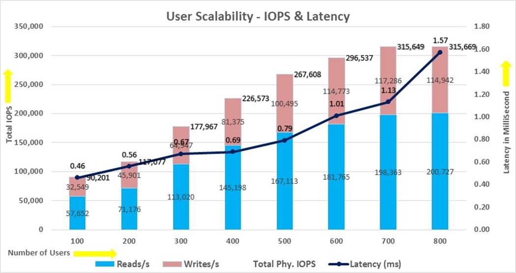
The chart below shows the TPM and System Utilization for the same above tests on CDBDB Database for running the workload from 100 users to 800 users:
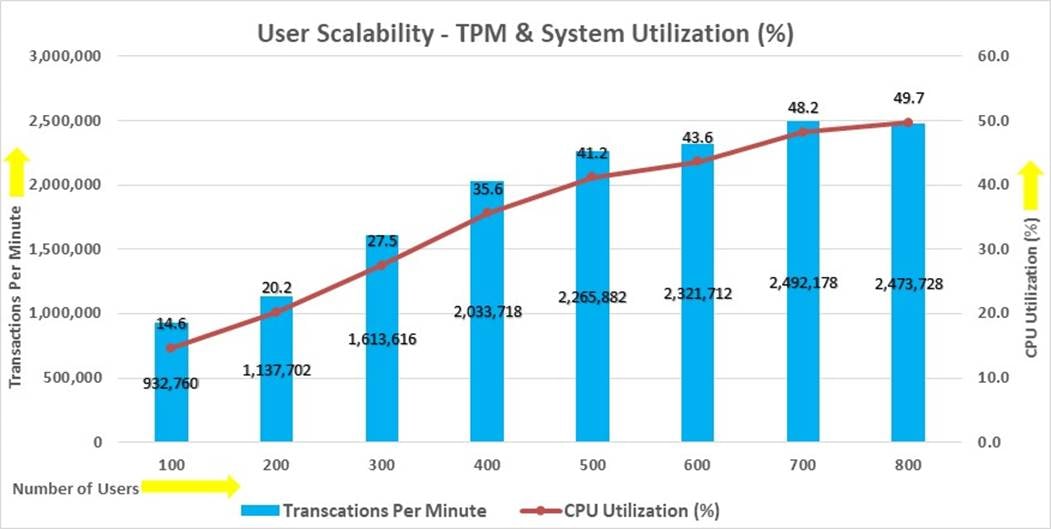
The screenshot below captures the Swingbench SOE workload running with 800 users on one OLTP Database. Oracle AWR report shows the “Top Timed Events” for the CDBDB database for the entire duration of the test:
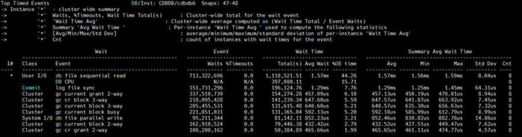
The screenshot below captured from the Oracle AWR report highlights the Physical Reads/Sec, Physical Writes/Sec and Transactions per Seconds for the Container CDBDB Database. We captured about 315k IOPS (200k Reads/s and 114k Writes/s) with the 41k TPS while running workload on one database:
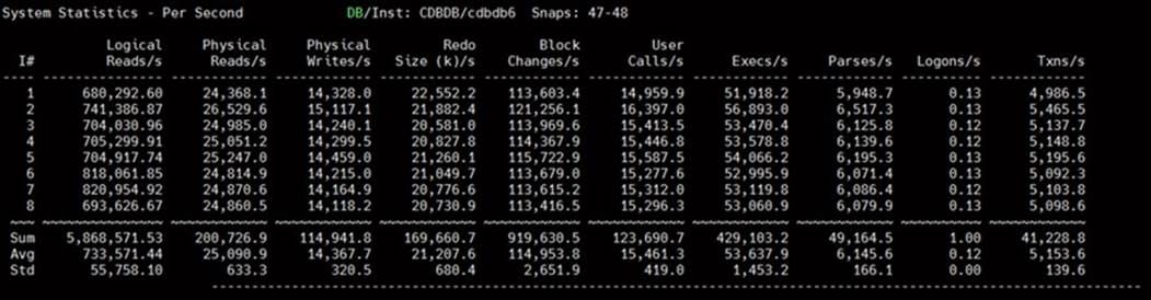
The screenshot below captured from the Oracle AWR report shows the CDBDB database “IO Profile” for the “Reads/s” and “Writes/s” requests for the entire test duration of the test. The Total Requests (Read and Write Per Second) were around “321k” with Total (MB) Read+Write Per Second was around “2741” MB/s for the CDBDB database while running the workload test on one database:
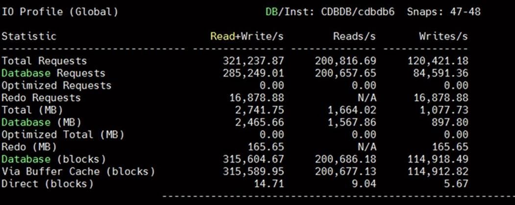
The screenshot below shows the Pure Storage array GUI when one OLTP database was running the workload. The screenshot shows the average IOPS “325k” with the average throughput of “2.9 GB/s” with the average latency around “0.6 millisecond:”
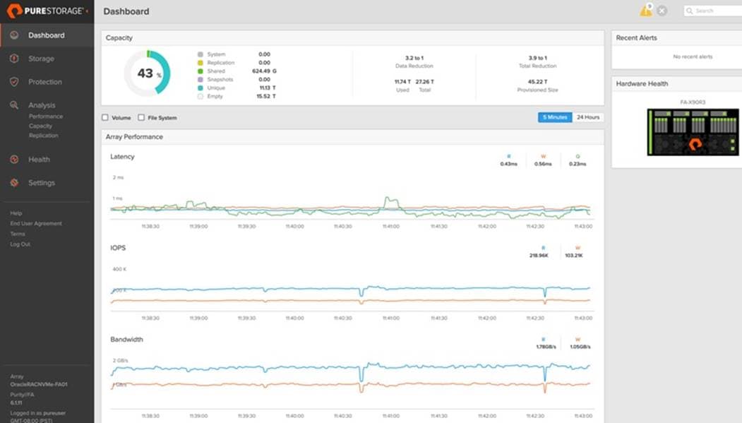
Also, we ran the Swingbench SOE workload with 800 users for a 24 Hour sustained test and captured the overall system performance for one OLTP Database. The screenshot below shows the Pure Storage array GUI when one OLTP database was running the workload for 24-hour window. The screenshot shows the average IOPS, throughput and latency for an entire 24-hour test duration and we observed the system performance was consistent throughout the test.
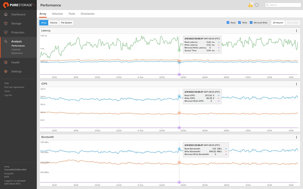
DSS database workloads are generally sequential in nature, read intensive and exercise large IO size. DSS database workload runs a small number of users that typically exercise extremely complex queries that run for hours. For running oracle database multitenancy architecture, we configured one container database as DSSDB and into that container, we created one pluggable database as PDBSH as explained earlier.
We configured 4.5 TB of PDBSH pluggable database by loading Swingbench “SH” schema into Datafile Tablespace. The screenshot below shows the database summary for the “DSSDB” database running for 12-hour duration. The container database “DSSDB” was also running with one pluggable databases “PDBSH” and the pluggable database was running the Swingbench SH workload for the entire 12-hour duration of the test.
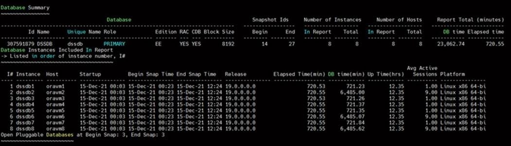
The screenshot below captured from the Oracle AWR report shows the DSSDB database “IO Profile” for the “Reads/s” and “Writes/s” requests for the entire 12-hour duration of the test. As the screenshots shows, the Total MB (Read and Write Per Second) were around “14,263 MB/s” for the DSSDB database while running this test:
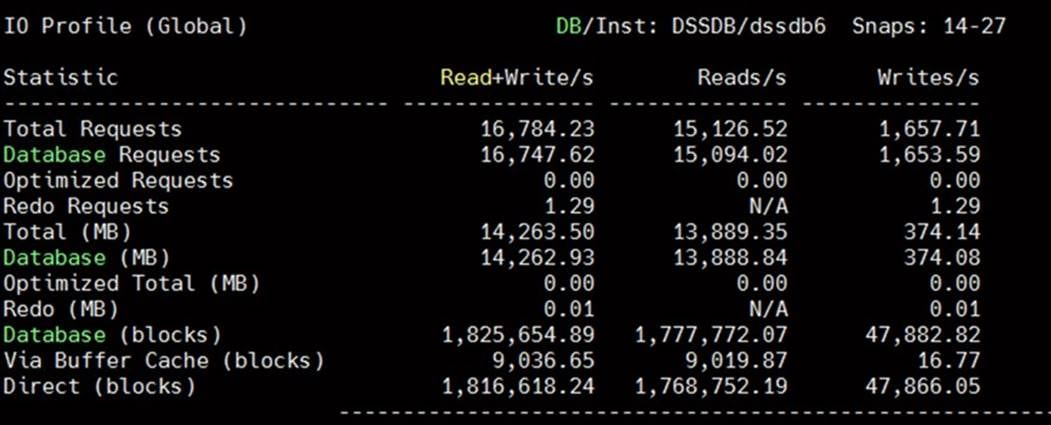
The screenshot shown below shows the Top Timed Events for 12-hour duration when workload was running on DSSDB database:
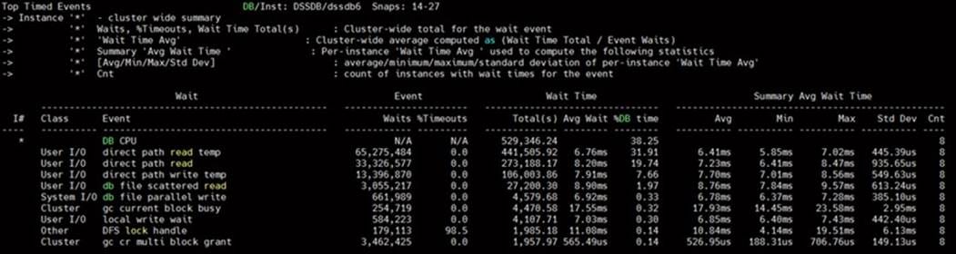
Multiple OLTP and DSS Databases Performance
In this test, we ran Swingbench SOE workloads on both OLTP (PDBSOE + PDBFIN) databases and Swingbench SH workload on one DSS (PDBSH) Database at the same time and captured the overall system performance. We captured the system performance on small random queries presented via OLTP databases as well as large and sequential transactions submitted via DSS database workload as documented below.
The screenshot below shows the database summary for the “CDBDB” database running for a 24-hour duration. The container database “CDBDB” was running with both the pluggable databases “PDBSOE” and “PDBFIN” and both the pluggable databases were running the Swingbench SOE workload for the entire duration of the test:
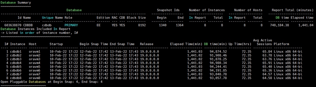
The screenshot below shows the database summary for the “DSSDB” database running for a 24-hour duration. The container database “DSSDB” was also running with one pluggable databases “PDBSH” and the pluggable database was running the Swingbench SH workload for the entire duration of the test:
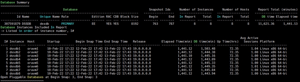
The screenshot shown below was captured from the Oracle AWR report while running the Swingbench SOE and SH workload tests on all three databases for 24-hours. The screenshot shows the “OS Statistics by Instance” while the system was running mixed workload. As shown below, the workload was equally spread across all the databases clusters while the average CPU utilization was around 30% overall:
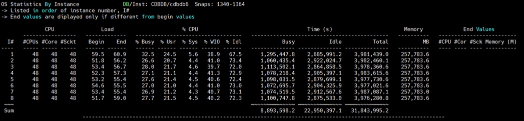
The screenshots below captured from the Oracle AWR report shows the “Top Timed Events” for the CDBDB and DSSDB database while running Swingbench mixed workloads on both the databases:
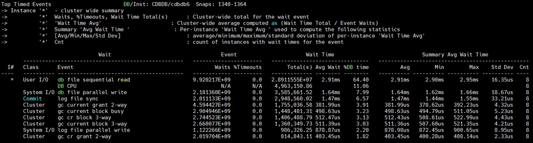
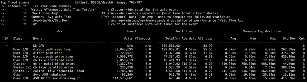
The screenshot below captured from the Oracle AWR report highlights the Physical Reads/Sec, Physical Writes/Sec and Transactions per Seconds for the Container CDBDB Database. We captured around 183k IOPS (119k Reads/s and 64k Writes/s) with the 23k TPS while running multiple databases workloads.
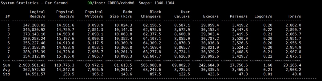
The screenshot below captured from the Oracle AWR report shows the CDBDB database “IO Profile” for the “Reads/s” and “Writes/s” requests for the entire 24-hour duration of the test. As the screenshots shows, the Total Requests (Read and Write Per Second) were around “191k” with Total (MB) Read+Write Per Second was around “1566” MB/s for the CDBDB database while running the mixed workload test:
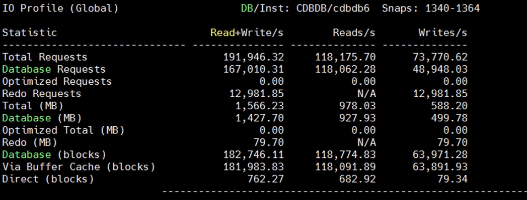
The screenshot below captured from the Oracle AWR report shows the DSSDB database “IO Profile” for the “Reads/s” and “Writes/s” requests for the entire duration of the test. As the screenshots shows, the Total MB (Read and Write Per Second) were around “4566 MB/s” for the DSSDB database while running this test:
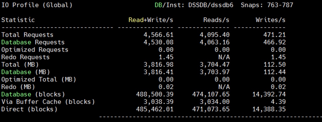
The screenshot below captured from the Oracle AWR report shows the CDBDB database “Interconnect Client Statistics Per Second”. As the screenshots shows, Interconnect Sent and Received Statistics were average around “1009 MB/s” while running the mixed workload test:
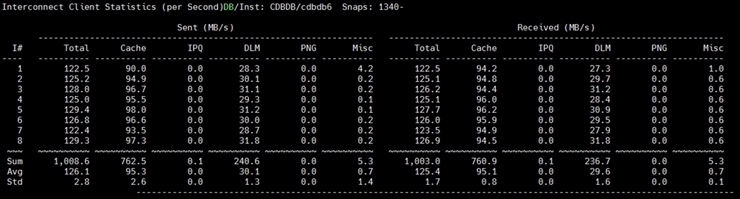
The screenshot below shows the Pure Storage FlashArray GUI for 24-hour sustained test when all the three databases were running the workloads at the same time. The screenshot shows the average IOPS “210k” with the average throughput of “5 GB/s” with the average latency around “1.5 millisecond:”
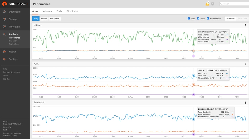
For the entire 24-hour test duration, we observed the system performance (IOPS and Throughput) was consistent throughout and we did not observe any dips in performance while running these tests.
This chapter is organized into the following subjects:
| Chapter |
Subject |
| Resiliency and Failure Tests |
Test 1 – Cisco UCS Chassis IOM Links Failure Test 3: One of the MDS Switch Failure |
The goal of these tests was to ensure that the reference architecture withstands commonly occurring failures due to either unexpected crashes, hardware failures or human errors. We conducted many hardware (disconnect power), software (process kills) and OS specific failures that simulate the real world scenarios under stress conditions. In the destructive testing, we will also demonstrate the unique failover capabilities of Cisco UCS components. Table 14 highlights the test cases.
Table 14. Hardware Failover Tests
| Test Scenario |
Tests Performed |
| Test 1: UCS Chassis IOM Links Failure |
Run the system on full Database workload. Disconnect one or two links from each Chassis 1 IOM and Chassis 2 IOM by pulling it out and reconnect it after 10-15 minutes. Capture the impact on overall database performance. |
| Test 2: One of the FI Failure |
Run the system on full Database workload. Power Off one of the Fabric Interconnect and check the network traffic on the other Fabric Interconnect and capture the impact on overall database performance. |
| Test 3: One of the MDS Switch Failure |
Run the system on full Database workload. Power Off one of the MDS switch and check the network and storage traffic on the other MDS switch. Capture the impact on overall database performance. |
| Test 4: Storage Controller Links Failure |
Run the system on full Database workload. Disconnect one or two FC links from each of the Pure Storage Controllers by pulling it out and reconnect it after 10-15 minutes. Capture the impact on overall database performance. |
| Test 5: ESXi/VM Server Node Failure |
Run the system on full Database workload. Power Off one of the ESXi Host and check the impact on database performance. |
Figure 10 illustrates various failure scenario which can be occurred due to either unexpected crashes or hardware failures.
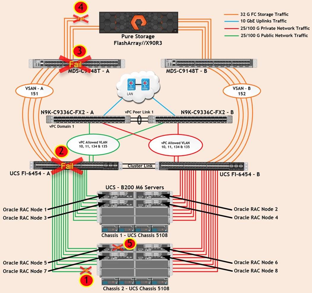
As shown in Figure 10, Scenario 1 represents the Chassis IOM links failures. Also, scenario 2 represents the UCS FI – A failure and similarly, scenario 3 represents the MDS Switch – A failure. Scenario 4 represents the Pure Storage Controllers link failures and Scenario 5 represents one of the ESXi Server Node Failure.
As previously explained in the vCenter Network configuration, we configured two Distributed Switches to carry VM Management Public Network, vMotion and Private Server to Server Oracle RAC Interconnect Network traffic and a Standard Switch to carry ESXi Management across both the Fabric Interconnects. We kept failover order in Distributed Port Group as ACTIVE/ACTIVE on both vmnic uplinks.
Note: All the Hardware failover tests were conducted with all three databases (PDBSOE, PDBFIN and PDBSH) running Swingbench mixed workloads.
Test 1 – Cisco UCS Chassis IOM Links Failure
We conducted IOM Links failure test on Cisco UCS Chassis 1 and Chassis 2 by disconnecting one of the server port link cables from the Chassis as shown below:
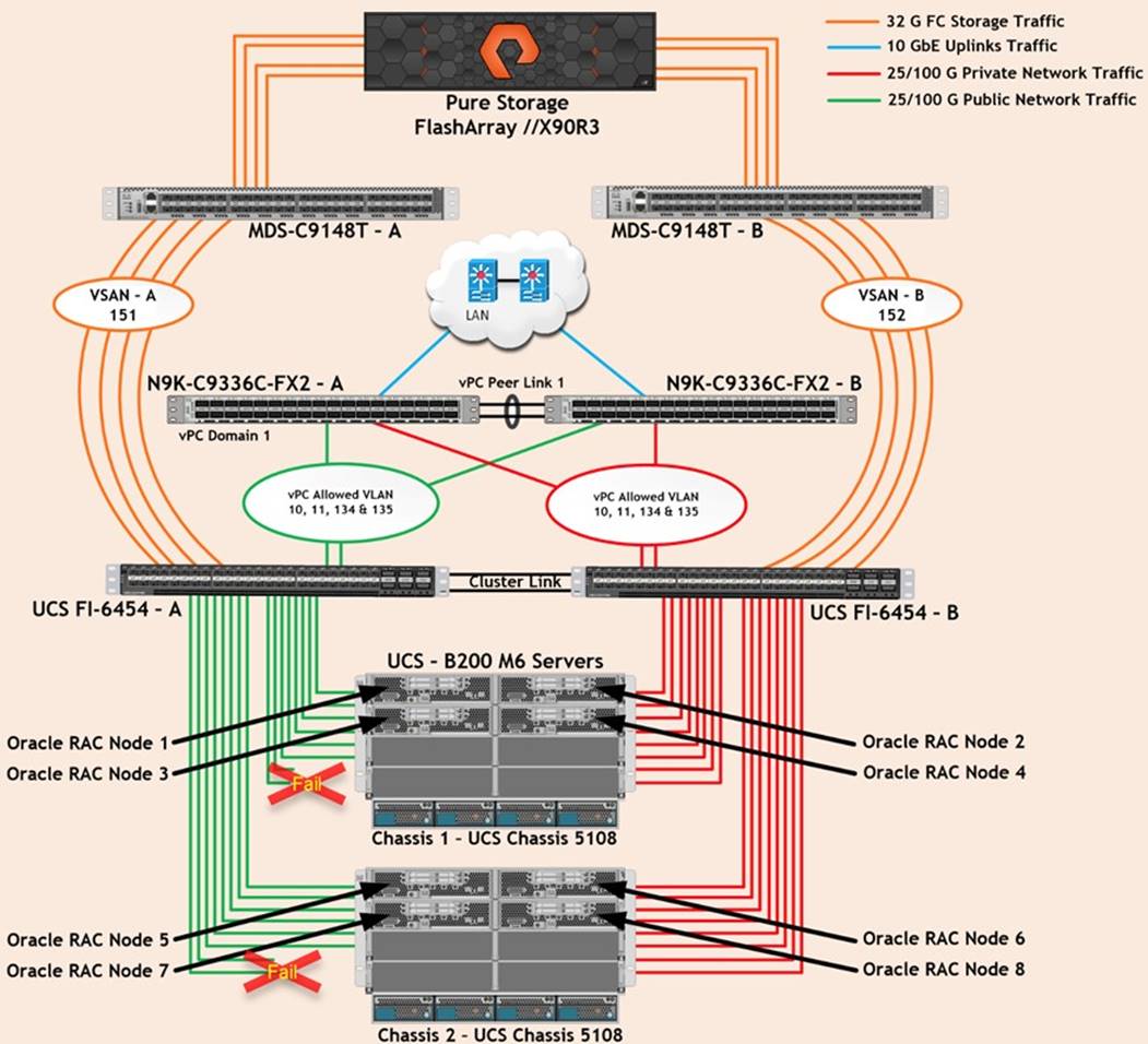
Unplug two server port cables from Chassis 1 and Chassis 2 each and check all the VLAN traffic information on both Cisco UCS FIs, Database and Pure Storage. The screenshot below shows the database workload performance from the storage array when multiple chassis links failed:
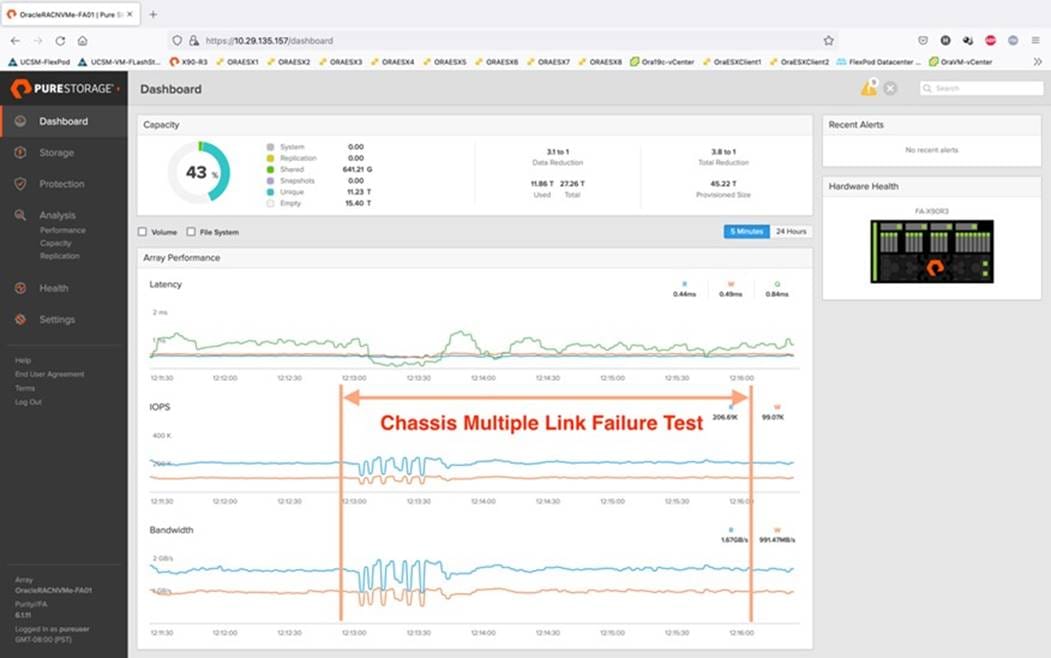
As shown in the screenshot above, we noticed no disruption in any of the network traffic and the database kept running under normal working conditions even after multiple IOM links failed from both the Chassis because of the Cisco UCS Port-Channel Feature. We kept the chassis links down for at least an hour and then reconnected those failed links and observed no disruption in network traffic and database operation.
We conducted a hardware failure test on FI – A by disconnecting the power cable to the Fabric Interconnect Switch.
The figure below illustrates how during FI – A switch failure, the respective nodes (ORAESX1, ORAESX2, ORAESX3 and ORAESX4) on chassis 1 and nodes (ORAESX5, ORAESX6, ORAESX7 and ORAESX8) on chassis 2 will re-route the VM Management Public Network, vMotion and Private Server to Server Oracle RAC Interconnect Network traffic through the healthy Fabric Interconnect Switch FI-B.
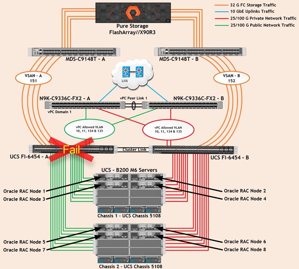
Log into FI – B and type “connect nxos” then type “show mac address-table” to see all VLAN connection on FI – B.
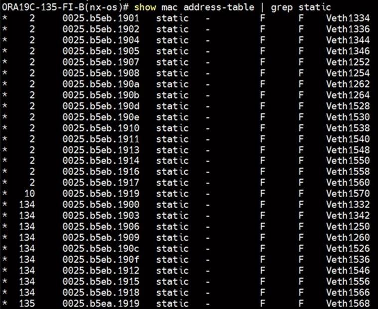
In the screenshot above, we noticed when the FI – A failed, all the MAC addresses of the redundant vNICs kept their VLANs network traffic going through FI – B. However, storage network traffic for VSAN 151 was not able to fail-over to another FI Switch and thus we lost half of the storage traffic connectivity paths from the Oracle RAC Databases to the Storage Array. The screenshot below shows the Pure Storage Array performance of the mixed workloads on all the databases while one of the FI was powered down:
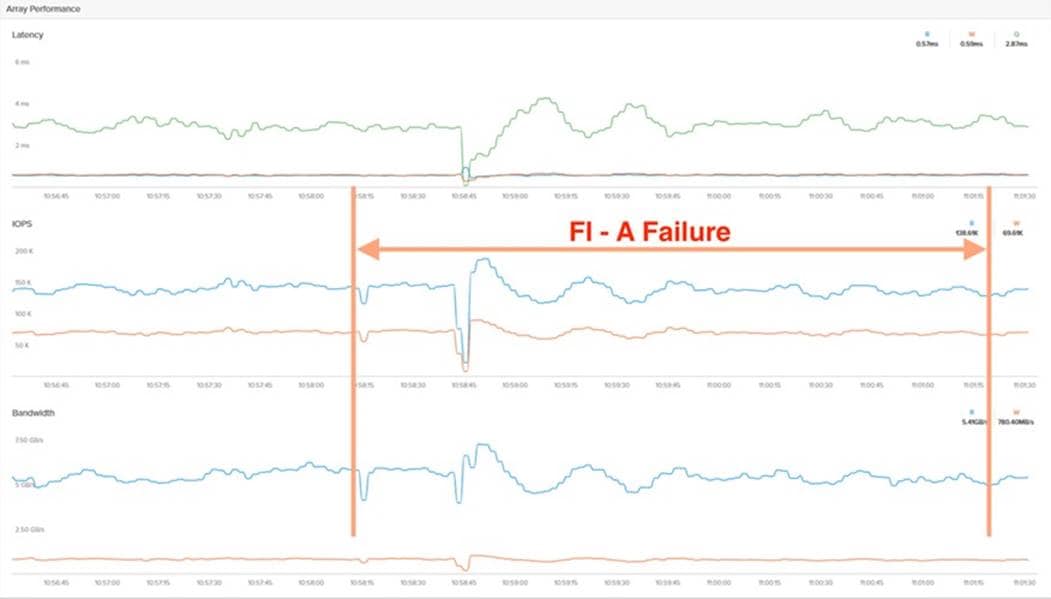
We also monitored and captured databases and its performance during this FI failure test through database alert log files and AWR reports. When we disconnected the power from FI – A, it caused a momentary impact on performance on the overall total IOPS, latency on OLTP as well as throughput on the DSS database for a few seconds but noticed that we did not see any interruption in any Private Server to Server Oracle RAC Interconnect Network, VM Management Public Network and vMotion network traffic on IO Service Requests to the storage. We observed the database workload kept running under normal conditions throughout duration of FI failure.
We noticed this behavior because each server node has pairs of vNICs placed on both the FI and configured those uplinks ports as ACTIVE/ACTIVE through a distributed switch. This will allow ESX Hosts to re-route all the ethernet traffic through the remaining active vmnic paths but there is no vHBA storage traffic failover from one FI switch to another switch. Therefore, in case of any one FI failure, we would lose half of the number of vHBAs or storage paths and consequently we observed a momentary databases performance impact for a few seconds on the overall system as shown above.
After plugging back the power cable to FI – A Switch, FI-A returns to a normal operating state and all the nodes to storage connectivity and ESXi Hosts configuration will bring back all the vmnics and vmhbas paths back to active, and database performance will resume at peak performance.
Test 3: One of the MDS Switch Fails
We conducted a hardware failure test on MDS Switch – A by disconnecting the power cable to the Switch and checking the storage network traffic on MDS Switch – B and the overall system as shown below:
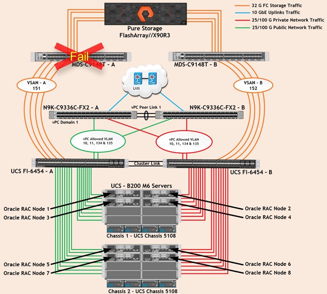
Like FI failure tests, we captured databases performances during this MDS Switch failure test and observed some performance impact on all three databases performance since we lost half of the VSAN (VSAN-A 151) traffic. While VSAN-A (151) stays locally into the switch and only carry storage traffic through the MDS switch A, VSAN-A doesn’t failover to MDS Switch B therefore we reduced server to storage connectivity into half during MDS Switch A failure. When we disconnected the power from MDS – A Switch, it caused a very momentary impact on performance of the overall total IOPS, latency on OLTP as well as throughput of the DSS database for a few seconds but noticed that we did not see any interruption in the overall Private Server to Server Oracle RAC Interconnect Network, VM Management Public Network and vMotion network traffic on I/O Service Requests to the storage as shown below:
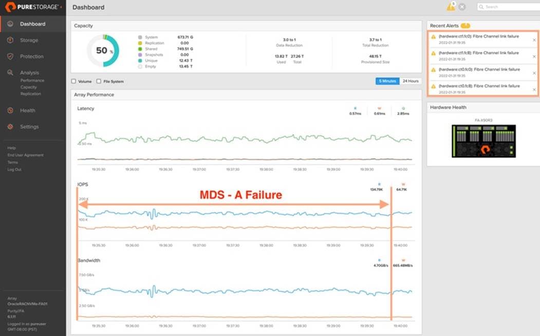
We observed that the database workload kept running under normal conditions throughout the duration of MDS failure.
After plugging back the power cable back into MDS – A Switch, MDS Switch returns to normal operating state and all the nodes to storage connectivity and ESXi Hosts configuration will bring back all the vmhbas path back to active and database performance will resume at peak performance.
Test 4: Storage Controller Links Failure
We performed a storage controller link failure test by disconnecting two of the FC links from the Pure Storage Array from each of the storage controllers as shown below:
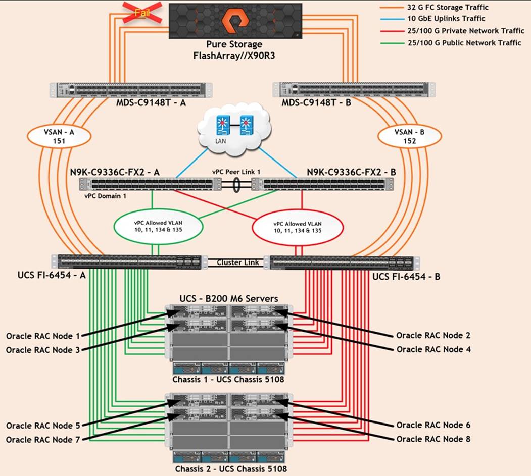
Like Chassis link failure tests, we noticed no disruption in any of the network and storage traffic and the database kept running under normal working conditions even after multiple FC storage links failed. After plugging back in the FC links to storage controller, MDS Switch and Storage array links comes back online, and database performance resumed to peak performance.
Test 5: ESXi Server Node Fails
In this test, we power down one ESXi node from the RAC cluster while the swingbench workload was running on all the databases and checked the overall system performance. We didn’t observe any performance impact on overall database performance for IOPS, latency and throughput after losing one of the nodes from the system.
We completed an additional failure scenario and validated that there was no single point of failure in this reference design.
Database administrators (DBA) and their IT departments face many challenges that demand a simplified Oracle RAC Database deployment and operation model providing high performance, availability and lower TCO. DBAs are under constant pressure to deliver fast response time to user applications. The current industry trend in data center design is towards shared infrastructures featuring multitenant workload deployments. Cisco Unified Computing System (Cisco UCS) is a next-generation data center platform that unites computing, network, storage access, and virtualization into a single cohesive system. Cisco UCS is an ideal platform for the architecture of mission critical database workloads such as Oracle RAC.
An essential feature for Oracle databases deployed on a shared enterprise system is the ability to deliver consistent and dependable high performance. High performance must be coupled with non-disruptive operations, high availability, scalability, and storage efficiency. Cisco and Pure Storage have partnered to deliver FlashStack solutions, which uses best-in-class storage, server, and network components to serve as the foundation for a variety of workloads, enabling efficient architectural designs that can be quickly and confidently deployed for enterprise applications. FlashStack's fully modular and non-disruptive architecture abstracts hardware into software for non-disruptive changes which allow customers to seamlessly deploy new technology without having to re-architect their data center solutions.
This pre-validated FlashStack architecture delivers proven value, agility, and performance that drive higher productivity, faster decision making, and greater opportunities for growth. The tests results demonstrate that this FlashStack solution built on NVMe storage delivers higher performance and optimizes the use of CPU resources on the Oracle database server by implementing VMware virtualization technologies. As Oracle database servers are typically licensed per CPU core, this gives our customers one more reason to optimize their Oracle licenses by consolidating their workloads on fewer hosts, thereby resulting in lower TCO. This FlashStack solution provides extremely high performance while maintaining the very low latency available via NVMe storage over FC.
The combination of Cisco UCS, Pure Storage, Oracle Real Application Cluster Database, and VMware architecture can provide the following benefits to accelerate your IT transformation:
● Cisco UCS stateless computing architecture provided by the Service Profile capability of Cisco UCS allows fast, non-disruptive workload changes to be executed simply and seamlessly across the integrated Cisco UCS infrastructure and Cisco x86 servers.
● A single platform built from unified compute, fabric, and storage technologies, allowing you to scale to large-scale data centers without architectural changes.
● Enabling faster deployments, greater flexibility of choice, efficiency, high availability, and lower risk.
Known Issues, Enhancements, Fixes, and Recommendations
This chapter is organized into the following subjects:
| Chapter |
Subject |
| Known Issues, Enhancements, Fixes, and Recommendations |
For this Oracle database solution deployment on VMWare, we observed IO pause during failure testing involving port channel membership changes. Removing a member link from a port channel between UCS FI and IOM results in IO to pause or drop from Virtual Machines to targets. Failure of a port in a port channel results in frame drops. VIC nfnic driver by design relies on IO timeout mechanism from OS layers above the driver. The IO request associated with the dropped frame would end up going through the upper layer IO timeout detection and handling process. The impacted IO would be outstanding for IO timeout duration. This shows up as IO pause If the application waits on this IO completion before sending more IOs. The default SCSI disk timeout value is 180 seconds on a VM running on ESX host. The large IO timeout value in combination with the VIC firmware and driver design that relies on upper layers for IO timeout handling results in IO pause for the duration of IO time out. This is the cause for Oracle application failures in this VMware environment.
IO pause in the problem scenario was eliminated by making UCSM/VIC firmware changes and improvement by performing the IO recovery immediately instead of waiting for the IO timeout. The fixes for the problem mentioned above were released into UCSM 4.2(1i) version. To avoid this issue, we also need to configure both the “Fabric Interconnect” vHBA reset property as detailed below.
Procedure 1. Configure Fabric Interconnect Default “Fab-PO vhba-reset”
Step 1. Login as Admin User into Fabric Interconnect – A and type “connect nxos.”
Step 2. Run the command “show system internal fcoe_mgr info global” and verify the system information as shown below:
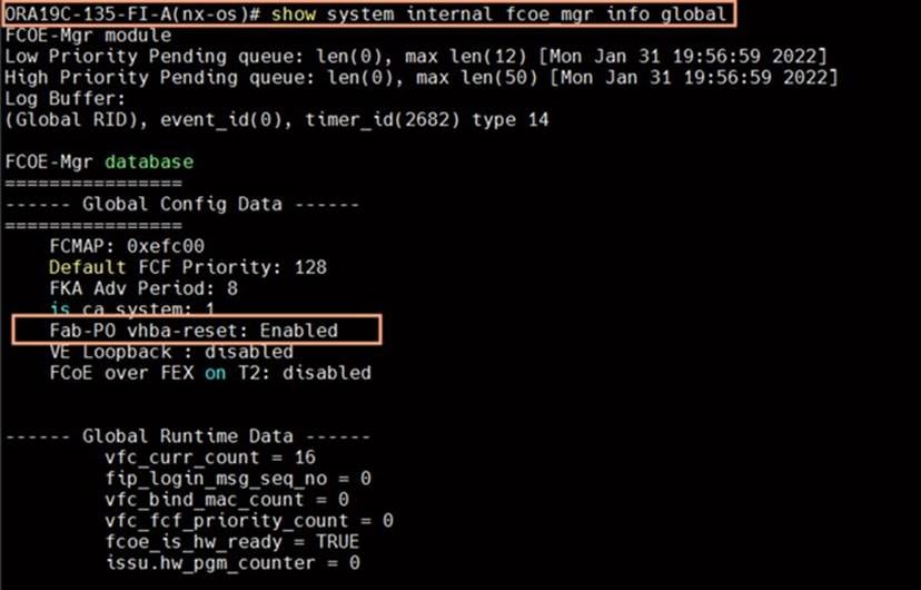
Step 3. By default, Fab-PO vhba-reset is Disabled.
Step 4. Run the following commands to change the value Enabled:
ORA21C-FI-A(nx-os)# exit
ORA21C-FI-A# scope eth-uplink
ORA21C-FI-A /eth-uplink # set fabric-pc-vhba-reset Enabled
ORA21C-FI-A /eth-uplink* # commit-buffer
ORA19C-135-FI-A /eth-uplink # show detail
Ethernet Uplink:
Mode: End Host
MAC Table Aging Time (dd:hh:mm:ss): Mode Default
VLAN Port Count Optimization: Disabled
Fabric Port Channel vHBA reset: Enabled
service for unsupported transceivers: Disabled
Current Task:
Step 5. Change the setting and reboot the Fabric Interconnect.
Step 6. Verify this settings on both Fabric Interconnects to keep Fabric Port Channel vHBA reset: Enabled.
Unresolved Issue and Enhancement
We repeated any random links failure test many times and most of the time the system runs fine without any performance issue but occasionally (1 out of 20 time), the link down caused the VM’s to reboot and database nodes (one or few) to crashes and eventually workload to stop.
The error below is captured from sample logs of one of the ESX node and caused multiple Oracle RAC nodes to crash as:
2022-01-28T19:39:55.596Z cpu98:2098250)ScsiClaimrule: 1861: Error claiming path vmhba2:C0:T39:L251. Failure.
2022-01-28T19:39:55.596Z cpu98:2098250)WARNING: NMP: nmp_PspClaimPath:145: Claim of path 'vmhba2:C0:T39:L252' by plugin VMW_PSP_RR for de vice 'naa.624a9370d168f966d4ad423800011cf2' failed. Failure
2022-01-28T19:39:55.596Z cpu98:2098250)WARNING: ScsiPath: 8726: Plugin 'NMP' had an error (Failure) while claiming path 'vmhba2:C0:T39:L2 52'. Skipping the path.
2022-01-28T19:39:55.596Z cpu98:2098250)ScsiClaimrule: 1557: Plugin NMP specified by claimrule 65535 was not able to claim path vmhba2:C0: T39:L252: Busy
2022-01-28T19:39:55.596Z cpu98:2098250)ScsiClaimrule: 1861: Error claiming path vmhba2:C0:T39:L252. Failure.
2022-01-28T19:39:55.596Z cpu98:2098250)WARNING: NMP: nmp_PspClaimPath:145: Claim of path 'vmhba2:C0:T39:L253' by plugin VMW_PSP_RR for de vice 'naa.624a9370d168f966d4ad423800011cf1' failed. Failure
2022-01-28T19:39:55.596Z cpu98:2098250)WARNING: ScsiPath: 8726: Plugin 'NMP' had an error (Failure) while claiming path 'vmhba2:C0:T39:L2 53'. Skipping the path.
2022-01-28T19:39:55.596Z cpu98:2098250)ScsiClaimrule: 1557: Plugin NMP specified by claimrule 65535 was not able to claim path vmhba2:C0: T39:L253: Busy
2022-01-28T19:39:55.596Z cpu98:2098250)ScsiClaimrule: 1861: Error claiming path vmhba2:C0:T39:L253. Failure.
2022-01-28T19:39:55.596Z cpu98:2098250)WARNING: NMP: nmp_PspClaimPath:145: Claim of path 'vmhba2:C0:T39:L254' by plugin VMW_PSP_RR for de vice 'naa.624a9370d168f966d4ad423800011cf0' failed. Failure
2022-01-28T19:39:55.596Z cpu98:2098250)WARNING: ScsiPath: 8726: Plugin 'NMP' had an error (Failure) while claiming path 'vmhba2:C0:T39:L2 54'. Skipping the path.
2022-01-28T19:39:55.596Z cpu98:2098250)ScsiClaimrule: 1557: Plugin NMP specified by claimrule 65535 was not able to claim path vmhba2:C0: T39:L254: Busy
2022-01-28T19:39:55.596Z cpu98:2098250)ScsiClaimrule: 1861: Error claiming path vmhba2:C0:T39:L254. Failure.
2022-01-28T19:39:55.922Z cpu19:2097820)nfnic: <4>: INFO: fnic_queuecommand: 722: returning IO as lun is inactive or tport is NULL. driver IO:0
2022-01-28T19:39:55.922Z cpu19:2097820)nfnic: <2>: INFO: fnic_queuecommand: 722: returning IO as lun is inactive or tport is NULL. driver IO:0
2022-01-28T19:39:55.922Z cpu19:2097820)nfnic: <4>: INFO: fnic_queuecommand: 722: returning IO as lun is inactive or tport is NULL. driver
Note: This issue was observed in the current 4.2(1i) NFNIC driver version used in this CVD. We are investigating this issue further and trying the newer VMware FNIC driver version -> 4.0.0.74 which has the fixes for this particular behavior.
The following references were used in preparing this document:
Cisco Unified Computing System
Pure Storage NVMe FlashArray //X
Cisco UCS Data Center Design Guides
FlashStack Converged Infrastructure
Pure Storage and Cisco Solutions
FlashArray VMware Best Practices
Virtualize an Oracle Database on VMware using Virtual Volumes
Tushar Patel, Principal Engineer, CSPG UCS Product Management and Data Center Solutions Engineering Group, Cisco Systems, Inc.
Tushar Patel is a Principal Engineer in Cisco Systems CSPG UCS Product Management and Data Center Solutions Engineering Group and a specialist in Flash Storage technologies and Oracle RAC RDBMS. Tushar has over 25 years of experience in Flash Storage architecture, Database architecture, design, and performance. Tushar also has strong background in Intel X86 architecture, hyper converged systems, Storage technologies and Virtualization. He has worked with large number of enterprise customers, evaluate, and deploy mission critical database solutions. Tushar has presented to both internal and external audiences at various conferences and customer events.
Hardikkumar Vyas, Technical Marketing Engineer, CSPG UCS Product Management and Data Center Solutions Engineering Group, Cisco Systems, Inc.
Hardikkumar Vyas is a Solution Engineer in Cisco Systems CSPG UCS Product Management and Data Center Solutions Engineering Group for configuring, implementing, and validating infrastructure best practices for highly available Oracle RAC databases solutions on Cisco UCS Servers, Cisco Nexus Products, and various Storage Technologies. Hardikkumar Vyas holds a master’s degree in Electrical Engineering and has over 8 years of experience working with Oracle RAC Databases and associated applications. Hardikkumar Vyas’s focus is developing database solutions on different platforms, perform benchmarks, prepare reference architectures, and write technical documents for Oracle RAC Databases on Cisco UCS Platforms.
Acknowledgements
For their support and contribution to the design, validation, and creation of this Cisco Validated Design, the authors would like to thank:
Cisco CSPG UCS Solutions, VIC, Engineering and QA Teams. Special thanks to: Eldho Jacob, Sesidhar Baddela, SalmanHasan, Dhiraj Kashyap, Saheli Basak Roy, Dhanraj Jhawar and Arulprabhu Ponnusamy
Rakesh Tikku, Oracle Solution Architect, Pure Storage, Inc.
Craig Waters, Technical Director, Pure Storage, Inc
Joe Houghes, Senior Solutions Architect, Pure Storage, Inc.
Appendices
This chapter is organized into the following subjects:
| Chapter |
Subject |
| MDS 9148T Switch Configuration |
|
| Cisco Nexus 9336C-FX2 Switch Configuration |
|
| Configuration of “/etc/sysctl.conf” into RHEL VM OS |
|
| Configuration of “/etc/security/limits.d/oracle-database-preinstall-19c.conf” into RHEL VM OS |
|
| Glossary of Terms |
|
| Glossary of Acronyms |
|
| Comments, Suggestions, and Discussion Links |
Appendix A—MDS 9148T Switch Configuration
ORA19C-FSVM-MDS-A# show running-config
!Command: show running-config
!No configuration change since last restart
!Time: Mon Jan 31 23:39:08 2022
version 8.4(2c)
power redundancy-mode redundant
system default switchport trunk mode auto
system default switchport mode F
feature fport-channel-trunk
no feature http-server
role name default-role
description This is a system defined role and applies to all users.
rule 5 permit show feature environment
rule 4 permit show feature hardware
rule 3 permit show feature module
rule 2 permit show feature snmp
rule 1 permit show feature system
no password strength-check
username admin password 5 $5$iZBzOFts$e1v7sIqYxeouc8.Yxd48b10f2gN9wnDDTd7qkzIN87B role network-admin
ip domain-lookup
ip host ORA19C-FSVM-MDS-A 10.29.135.155
aaa group server radius radius
snmp-server user admin network-admin auth md5 0x9b1b4f1db4d3c1e06d622e30359f0f37 priv 0x9b1b4f1db4d3c1e06d622e30359f0f37 localizedkey
rmon event 1 log trap public description FATAL(1) owner PMON@FATAL
rmon event 2 log trap public description CRITICAL(2) owner PMON@CRITICAL
rmon event 3 log trap public description ERROR(3) owner PMON@ERROR
rmon event 4 log trap public description WARNING(4) owner PMON@WARNING
rmon event 5 log trap public description INFORMATION(5) owner PMON@INFO
ntp server 72.163.32.44
vsan database
vsan 151 name "VSAN-FI-A"
device-alias mode enhanced
device-alias database
device-alias name ORAESX1-hba0 pwwn 20:00:00:25:b5:e7:aa:00
device-alias name ORAESX1-hba2 pwwn 20:00:00:25:b5:e7:aa:01
device-alias name ORAESX2-hba0 pwwn 20:00:00:25:b5:e7:aa:02
device-alias name ORAESX2-hba2 pwwn 20:00:00:25:b5:e7:aa:03
device-alias name ORAESX3-hba0 pwwn 20:00:00:25:b5:e7:aa:04
device-alias name ORAESX3-hba2 pwwn 20:00:00:25:b5:e7:aa:05
device-alias name ORAESX4-hba0 pwwn 20:00:00:25:b5:e7:aa:06
device-alias name ORAESX4-hba2 pwwn 20:00:00:25:b5:e7:aa:07
device-alias name ORAESX5-hba0 pwwn 20:00:00:25:b5:e7:aa:08
device-alias name ORAESX5-hba2 pwwn 20:00:00:25:b5:e7:aa:09
device-alias name ORAESX6-hba0 pwwn 20:00:00:25:b5:e7:aa:0a
device-alias name ORAESX6-hba2 pwwn 20:00:00:25:b5:e7:aa:0b
device-alias name ORAESX7-hba0 pwwn 20:00:00:25:b5:e7:aa:0c
device-alias name ORAESX7-hba2 pwwn 20:00:00:25:b5:e7:aa:0d
device-alias name ORAESX8-hba0 pwwn 20:00:00:25:b5:e7:aa:0e
device-alias name ORAESX8-hba2 pwwn 20:00:00:25:b5:e7:aa:0f
device-alias name OracleRACNVMe-FA01-CT0-FC0 pwwn 52:4a:93:7b:31:c5:19:00
device-alias name OracleRACNVMe-FA01-CT0-FC8 pwwn 52:4a:93:7b:31:c5:19:08
device-alias name OracleRACNVMe-FA01-CT1-FC0 pwwn 52:4a:93:7b:31:c5:19:10
device-alias name OracleRACNVMe-FA01-CT1-FC8 pwwn 52:4a:93:7b:31:c5:19:18
device-alias commit
fcdomain fcid database
vsan 1 wwn 21:00:00:0e:1e:e8:c6:82 fcid 0x5e0000 dynamic
vsan 151 wwn 52:4a:93:7b:31:c5:19:00 fcid 0x820000 dynamic
! [OracleRACNVMe-FA01-CT0-FC0]
vsan 151 wwn 52:4a:93:7b:31:c5:19:08 fcid 0x820020 dynamic
! [OracleRACNVMe-FA01-CT0-FC8]
vsan 151 wwn 52:4a:93:7b:31:c5:19:10 fcid 0x820040 dynamic
! [OracleRACNVMe-FA01-CT1-FC0]
vsan 151 wwn 52:4a:93:7b:31:c5:19:18 fcid 0x820060 dynamic
! [OracleRACNVMe-FA01-CT1-FC8]
vsan 151 wwn 20:01:00:3a:9c:da:97:e0 fcid 0x820080 dynamic
vsan 151 wwn 20:03:00:3a:9c:da:97:e0 fcid 0x8200a0 dynamic
vsan 151 wwn 20:02:00:3a:9c:da:97:e0 fcid 0x8200c0 dynamic
vsan 151 wwn 20:04:00:3a:9c:da:97:e0 fcid 0x8200e0 dynamic
vsan 151 wwn 20:00:00:25:b5:e7:aa:04 fcid 0x820081 dynamic
! [ORAESX3-hba0]
vsan 151 wwn 20:00:00:25:b5:e7:aa:05 fcid 0x820082 dynamic
! [ORAESX3-hba2]
vsan 151 wwn 20:00:00:25:b5:e7:aa:06 fcid 0x820083 dynamic
! [ORAESX4-hba0]
vsan 151 wwn 20:00:00:25:b5:e7:aa:00 fcid 0x820084 dynamic
! [ORAESX1-hba0]
vsan 151 wwn 20:00:00:25:b5:e7:aa:07 fcid 0x820085 dynamic
! [ORAESX4-hba2]
vsan 151 wwn 20:00:00:25:b5:e7:aa:01 fcid 0x820086 dynamic
! [ORAESX1-hba2]
vsan 151 wwn 20:00:00:25:b5:e7:aa:02 fcid 0x820087 dynamic
! [ORAESX2-hba0]
vsan 151 wwn 20:00:00:25:b5:e7:aa:03 fcid 0x820088 dynamic
! [ORAESX2-hba2]
vsan 151 wwn 20:00:00:25:b5:e7:aa:08 fcid 0x820089 dynamic
! [ORAESX5-hba0]
vsan 151 wwn 20:00:00:25:b5:e7:aa:09 fcid 0x82008a dynamic
! [ORAESX5-hba2]
vsan 151 wwn 20:00:00:25:b5:e7:aa:0a fcid 0x82008b dynamic
! [ORAESX6-hba0]
vsan 151 wwn 20:00:00:25:b5:e7:aa:0b fcid 0x82008c dynamic
! [ORAESX6-hba2]
vsan 151 wwn 20:00:00:25:b5:e7:aa:0c fcid 0x82008d dynamic
! [ORAESX7-hba0]
vsan 151 wwn 20:00:00:25:b5:e7:aa:0d fcid 0x82008e dynamic
! [ORAESX7-hba2]
vsan 151 wwn 20:00:00:25:b5:e7:aa:0e fcid 0x82008f dynamic
! [ORAESX8-hba0]
vsan 151 wwn 20:00:00:25:b5:e7:aa:0f fcid 0x820090 dynamic
! [ORAESX8-hba2]
vsan 151 wwn 24:fb:00:3a:9c:da:97:e0 fcid 0x820100 dynamic
zone smart-zoning enable vsan 151
!Active Zone Database Section for vsan 151
zone name ORAESX1A vsan 151
member pwwn 20:00:00:25:b5:e7:aa:00 init
! [ORAESX1-hba0]
member pwwn 20:00:00:25:b5:e7:aa:01 init
! [ORAESX1-hba2]
member pwwn 52:4a:93:7b:31:c5:19:00 target
! [OracleRACNVMe-FA01-CT0-FC0]
member pwwn 52:4a:93:7b:31:c5:19:08 target
! [OracleRACNVMe-FA01-CT0-FC8]
member pwwn 52:4a:93:7b:31:c5:19:10 target
! [OracleRACNVMe-FA01-CT1-FC0]
member pwwn 52:4a:93:7b:31:c5:19:18 target
! [OracleRACNVMe-FA01-CT1-FC8]
zone name ORAESX2A vsan 151
member pwwn 20:00:00:25:b5:e7:aa:02 init
! [ORAESX2-hba0]
member pwwn 20:00:00:25:b5:e7:aa:03 init
! [ORAESX2-hba2]
member pwwn 52:4a:93:7b:31:c5:19:00 target
! [OracleRACNVMe-FA01-CT0-FC0]
member pwwn 52:4a:93:7b:31:c5:19:08 target
! [OracleRACNVMe-FA01-CT0-FC8]
member pwwn 52:4a:93:7b:31:c5:19:10 target
! [OracleRACNVMe-FA01-CT1-FC0]
member pwwn 52:4a:93:7b:31:c5:19:18 target
! [OracleRACNVMe-FA01-CT1-FC8]
zone name ORAESX3A vsan 151
member pwwn 20:00:00:25:b5:e7:aa:04 init
! [ORAESX3-hba0]
member pwwn 20:00:00:25:b5:e7:aa:05 init
! [ORAESX3-hba2]
member pwwn 52:4a:93:7b:31:c5:19:00 target
! [OracleRACNVMe-FA01-CT0-FC0]
member pwwn 52:4a:93:7b:31:c5:19:08 target
! [OracleRACNVMe-FA01-CT0-FC8]
member pwwn 52:4a:93:7b:31:c5:19:10 target
! [OracleRACNVMe-FA01-CT1-FC0]
member pwwn 52:4a:93:7b:31:c5:19:18 target
! [OracleRACNVMe-FA01-CT1-FC8]
zone name ORAESX4A vsan 151
member pwwn 20:00:00:25:b5:e7:aa:06 init
! [ORAESX4-hba0]
member pwwn 20:00:00:25:b5:e7:aa:07 init
! [ORAESX4-hba2]
member pwwn 52:4a:93:7b:31:c5:19:00 target
! [OracleRACNVMe-FA01-CT0-FC0]
member pwwn 52:4a:93:7b:31:c5:19:08 target
! [OracleRACNVMe-FA01-CT0-FC8]
member pwwn 52:4a:93:7b:31:c5:19:10 target
! [OracleRACNVMe-FA01-CT1-FC0]
member pwwn 52:4a:93:7b:31:c5:19:18 target
! [OracleRACNVMe-FA01-CT1-FC8]
zone name ORAESX5A vsan 151
member pwwn 20:00:00:25:b5:e7:aa:08 init
! [ORAESX5-hba0]
member pwwn 20:00:00:25:b5:e7:aa:09 init
! [ORAESX5-hba2]
member pwwn 52:4a:93:7b:31:c5:19:00 target
! [OracleRACNVMe-FA01-CT0-FC0]
member pwwn 52:4a:93:7b:31:c5:19:08 target
! [OracleRACNVMe-FA01-CT0-FC8]
member pwwn 52:4a:93:7b:31:c5:19:10 target
! [OracleRACNVMe-FA01-CT1-FC0]
member pwwn 52:4a:93:7b:31:c5:19:18 target
! [OracleRACNVMe-FA01-CT1-FC8]
zone name ORAESX6A vsan 151
member pwwn 20:00:00:25:b5:e7:aa:0a init
! [ORAESX6-hba0]
member pwwn 20:00:00:25:b5:e7:aa:0b init
! [ORAESX6-hba2]
member pwwn 52:4a:93:7b:31:c5:19:00 target
! [OracleRACNVMe-FA01-CT0-FC0]
member pwwn 52:4a:93:7b:31:c5:19:08 target
! [OracleRACNVMe-FA01-CT0-FC8]
member pwwn 52:4a:93:7b:31:c5:19:10 target
! [OracleRACNVMe-FA01-CT1-FC0]
member pwwn 52:4a:93:7b:31:c5:19:18 target
! [OracleRACNVMe-FA01-CT1-FC8]
zone name ORAESX7A vsan 151
member pwwn 20:00:00:25:b5:e7:aa:0c init
! [ORAESX7-hba0]
member pwwn 20:00:00:25:b5:e7:aa:0d init
! [ORAESX7-hba2]
member pwwn 52:4a:93:7b:31:c5:19:00 target
! [OracleRACNVMe-FA01-CT0-FC0]
member pwwn 52:4a:93:7b:31:c5:19:08 target
! [OracleRACNVMe-FA01-CT0-FC8]
member pwwn 52:4a:93:7b:31:c5:19:10 target
! [OracleRACNVMe-FA01-CT1-FC0]
member pwwn 52:4a:93:7b:31:c5:19:18 target
! [OracleRACNVMe-FA01-CT1-FC8]
zone name ORAESX8A vsan 151
member pwwn 20:00:00:25:b5:e7:aa:0e init
! [ORAESX8-hba0]
member pwwn 20:00:00:25:b5:e7:aa:0f init
! [ORAESX8-hba2]
member pwwn 52:4a:93:7b:31:c5:19:00 target
! [OracleRACNVMe-FA01-CT0-FC0]
member pwwn 52:4a:93:7b:31:c5:19:08 target
! [OracleRACNVMe-FA01-CT0-FC8]
member pwwn 52:4a:93:7b:31:c5:19:10 target
! [OracleRACNVMe-FA01-CT1-FC0]
member pwwn 52:4a:93:7b:31:c5:19:18 target
! [OracleRACNVMe-FA01-CT1-FC8]
zoneset name ORAESX-A vsan 151
member ORAESX1A
member ORAESX2A
member ORAESX3A
member ORAESX4A
member ORAESX5A
member ORAESX6A
member ORAESX7A
member ORAESX8A
zoneset activate name ORAESX-A vsan 151
do clear zone database vsan 151
!Full Zone Database Section for vsan 151
zone name ORAESX1A vsan 151
member pwwn 20:00:00:25:b5:e7:aa:00 init
! [ORAESX1-hba0]
member pwwn 20:00:00:25:b5:e7:aa:01 init
! [ORAESX1-hba2]
member pwwn 52:4a:93:7b:31:c5:19:00 target
! [OracleRACNVMe-FA01-CT0-FC0]
member pwwn 52:4a:93:7b:31:c5:19:08 target
! [OracleRACNVMe-FA01-CT0-FC8]
member pwwn 52:4a:93:7b:31:c5:19:10 target
! [OracleRACNVMe-FA01-CT1-FC0]
member pwwn 52:4a:93:7b:31:c5:19:18 target
! [OracleRACNVMe-FA01-CT1-FC8]
zone name ORAESX2A vsan 151
member pwwn 20:00:00:25:b5:e7:aa:02 init
! [ORAESX2-hba0]
member pwwn 20:00:00:25:b5:e7:aa:03 init
! [ORAESX2-hba2]
member pwwn 52:4a:93:7b:31:c5:19:00 target
! [OracleRACNVMe-FA01-CT0-FC0]
member pwwn 52:4a:93:7b:31:c5:19:08 target
! [OracleRACNVMe-FA01-CT0-FC8]
member pwwn 52:4a:93:7b:31:c5:19:10 target
! [OracleRACNVMe-FA01-CT1-FC0]
member pwwn 52:4a:93:7b:31:c5:19:18 target
! [OracleRACNVMe-FA01-CT1-FC8]
zone name ORAESX3A vsan 151
member pwwn 20:00:00:25:b5:e7:aa:04 init
! [ORAESX3-hba0]
member pwwn 20:00:00:25:b5:e7:aa:05 init
! [ORAESX3-hba2]
member pwwn 52:4a:93:7b:31:c5:19:00 target
! [OracleRACNVMe-FA01-CT0-FC0]
member pwwn 52:4a:93:7b:31:c5:19:08 target
! [OracleRACNVMe-FA01-CT0-FC8]
member pwwn 52:4a:93:7b:31:c5:19:10 target
! [OracleRACNVMe-FA01-CT1-FC0]
member pwwn 52:4a:93:7b:31:c5:19:18 target
! [OracleRACNVMe-FA01-CT1-FC8]
zone name ORAESX4A vsan 151
member pwwn 20:00:00:25:b5:e7:aa:06 init
! [ORAESX4-hba0]
member pwwn 20:00:00:25:b5:e7:aa:07 init
! [ORAESX4-hba2]
member pwwn 52:4a:93:7b:31:c5:19:00 target
! [OracleRACNVMe-FA01-CT0-FC0]
member pwwn 52:4a:93:7b:31:c5:19:08 target
! [OracleRACNVMe-FA01-CT0-FC8]
member pwwn 52:4a:93:7b:31:c5:19:10 target
! [OracleRACNVMe-FA01-CT1-FC0]
member pwwn 52:4a:93:7b:31:c5:19:18 target
! [OracleRACNVMe-FA01-CT1-FC8]
zone name ORAESX5A vsan 151
member pwwn 20:00:00:25:b5:e7:aa:08 init
! [ORAESX5-hba0]
member pwwn 20:00:00:25:b5:e7:aa:09 init
! [ORAESX5-hba2]
member pwwn 52:4a:93:7b:31:c5:19:00 target
! [OracleRACNVMe-FA01-CT0-FC0]
member pwwn 52:4a:93:7b:31:c5:19:08 target
! [OracleRACNVMe-FA01-CT0-FC8]
member pwwn 52:4a:93:7b:31:c5:19:10 target
! [OracleRACNVMe-FA01-CT1-FC0]
member pwwn 52:4a:93:7b:31:c5:19:18 target
! [OracleRACNVMe-FA01-CT1-FC8]
zone name ORAESX6A vsan 151
member pwwn 20:00:00:25:b5:e7:aa:0a init
! [ORAESX6-hba0]
member pwwn 20:00:00:25:b5:e7:aa:0b init
! [ORAESX6-hba2]
member pwwn 52:4a:93:7b:31:c5:19:00 target
! [OracleRACNVMe-FA01-CT0-FC0]
member pwwn 52:4a:93:7b:31:c5:19:08 target
! [OracleRACNVMe-FA01-CT0-FC8]
member pwwn 52:4a:93:7b:31:c5:19:10 target
! [OracleRACNVMe-FA01-CT1-FC0]
member pwwn 52:4a:93:7b:31:c5:19:18 target
! [OracleRACNVMe-FA01-CT1-FC8]
zone name ORAESX7A vsan 151
member pwwn 20:00:00:25:b5:e7:aa:0c init
! [ORAESX7-hba0]
member pwwn 20:00:00:25:b5:e7:aa:0d init
! [ORAESX7-hba2]
member pwwn 52:4a:93:7b:31:c5:19:00 target
! [OracleRACNVMe-FA01-CT0-FC0]
member pwwn 52:4a:93:7b:31:c5:19:08 target
! [OracleRACNVMe-FA01-CT0-FC8]
member pwwn 52:4a:93:7b:31:c5:19:10 target
! [OracleRACNVMe-FA01-CT1-FC0]
member pwwn 52:4a:93:7b:31:c5:19:18 target
! [OracleRACNVMe-FA01-CT1-FC8]
zone name ORAESX8A vsan 151
member pwwn 20:00:00:25:b5:e7:aa:0e init
! [ORAESX8-hba0]
member pwwn 20:00:00:25:b5:e7:aa:0f init
! [ORAESX8-hba2]
member pwwn 52:4a:93:7b:31:c5:19:00 target
! [OracleRACNVMe-FA01-CT0-FC0]
member pwwn 52:4a:93:7b:31:c5:19:08 target
! [OracleRACNVMe-FA01-CT0-FC8]
member pwwn 52:4a:93:7b:31:c5:19:10 target
! [OracleRACNVMe-FA01-CT1-FC0]
member pwwn 52:4a:93:7b:31:c5:19:18 target
! [OracleRACNVMe-FA01-CT1-FC8]
zoneset name ORAESX-A vsan 151
member ORAESX1A
member ORAESX2A
member ORAESX3A
member ORAESX4A
member ORAESX5A
member ORAESX6A
member ORAESX7A
member ORAESX8A
interface mgmt0
ip address 10.29.135.155 255.255.255.0
interface port-channel251
switchport trunk allowed vsan 151
switchport description ORA19C-FSVM-FI-A
switchport rate-mode dedicated
switchport trunk mode off
vsan database
vsan 151 interface port-channel251
vsan 151 interface fc1/5
vsan 151 interface fc1/6
vsan 151 interface fc1/7
vsan 151 interface fc1/8
vsan 151 interface fc1/9
vsan 151 interface fc1/10
vsan 151 interface fc1/11
vsan 151 interface fc1/12
switchname ORA19C-FSVM-MDS-A
cli alias name autozone source sys/autozone.py
line console
line vty
boot kickstart bootflash:/m9148-s6ek9-kickstart-mz.8.4.2c.bin
boot system bootflash:/m9148-s6ek9-mz.8.4.2c.bin
interface fc1/5
switchport speed auto
interface fc1/6
switchport speed auto
interface fc1/7
switchport speed auto
interface fc1/8
switchport speed auto
interface fc1/1
switchport speed auto
interface fc1/2
switchport speed auto
interface fc1/3
switchport speed auto
interface fc1/4
switchport speed auto
interface fc1/9
switchport mode auto
interface fc1/10
switchport mode auto
interface fc1/11
switchport mode auto
interface fc1/12
switchport mode auto
interface fc1/5
switchport mode auto
interface fc1/6
switchport mode auto
interface fc1/7
switchport mode auto
interface fc1/8
switchport mode auto
interface fc1/1
switchport mode auto
interface fc1/2
switchport mode auto
interface fc1/3
switchport mode auto
interface fc1/4
switchport mode auto
interface fc1/1
switchport description ORA19C-FSVM-FI-A-1/1
switchport trunk mode off
port-license acquire
channel-group 251 force
no shutdown
interface fc1/2
switchport description ORA19C-FSVM-FI-A-1/2
switchport trunk mode off
port-license acquire
channel-group 251 force
no shutdown
interface fc1/3
switchport description ORA19C-FSVM-FI-A-1/3
switchport trunk mode off
port-license acquire
channel-group 251 force
no shutdown
interface fc1/4
switchport description ORA19C-FSVM-FI-A-1/4
switchport trunk mode off
port-license acquire
channel-group 251 force
no shutdown
interface fc1/5
switchport trunk allowed vsan 151
switchport description OracleRACNVMe-FA01-CT0.FC0
switchport trunk mode off
port-license acquire
no shutdown
interface fc1/6
switchport trunk allowed vsan 151
switchport description OracleRACNVMe-FA01-CT0.FC8
switchport trunk mode off
port-license acquire
no shutdown
interface fc1/7
switchport trunk allowed vsan 151
switchport description OracleRACNVMe-FA01-CT1.FC0
switchport trunk mode off
port-license acquire
no shutdown
interface fc1/8
switchport trunk allowed vsan 151
switchport description OracleRACNVMe-FA01-CT1.FC8
switchport trunk mode off
port-license acquire
no shutdown
ip default-gateway 10.29.135.1
Appendix B— Cisco Nexus 9336C-FX2 Switch Configuration
ORA19C-135-N9K-A# show running-config
!Command: show running-config
!No configuration change since last restart
!Time: Mon Jan 31 23:28:02 2022
version 9.3(2) Bios:version 05.39
switchname ORA19C-135-N9K-A
policy-map type network-qos jumbo
class type network-qos class-default
mtu 9216
vdc ORA19C-135-N9K-A id 1
limit-resource vlan minimum 16 maximum 4094
limit-resource vrf minimum 2 maximum 4096
limit-resource port-channel minimum 0 maximum 511
limit-resource u4route-mem minimum 248 maximum 248
limit-resource u6route-mem minimum 96 maximum 96
limit-resource m4route-mem minimum 58 maximum 58
limit-resource m6route-mem minimum 8 maximum 8
cfs eth distribute
feature udld
feature interface-vlan
feature hsrp
feature lacp
feature vpc
feature lldp
no password strength-check
username admin password 5 $5$N58BF01y$kucMhdG4wEdLYUgzkwEvR8rtBud44d2fzZMK7vT.JZ3 role network-admin
ip domain-lookup
system default switchport
system qos
service-policy type network-qos jumbo
copp profile strict
snmp-server user admin network-admin auth md5 0x26c2815b034029874865f302c13f1470 priv 0x26c2815b034029874865f302c13f1470 localizedkey
rmon event 1 description FATAL(1) owner PMON@FATAL
rmon event 2 description CRITICAL(2) owner PMON@CRITICAL
rmon event 3 description ERROR(3) owner PMON@ERROR
rmon event 4 description WARNING(4) owner PMON@WARNING
rmon event 5 description INFORMATION(5) owner PMON@INFO
ntp server 72.163.32.44 use-vrf default
vlan 1,10-12,134-135
vlan 2
name Native_VLAN
vlan 10
name Oracle_RAC_Private_Network
vlan 11
name vMotion
vlan 12
name Backup_Oracle_VM
vlan 134
name ESX_Public_Network
vlan 135
name Oracle_RAC_Public_Network
spanning-tree port type edge bpduguard default
spanning-tree port type network default
vrf context management
ip route 0.0.0.0/0 10.29.135.1
port-channel load-balance src-dst l4port
vpc domain 1
peer-keepalive destination 10.29.135.154 source 10.29.135.153
auto-recovery
interface Vlan1
interface port-channel1
description vPC peer-link
switchport mode trunk
switchport trunk allowed vlan 1,10-12,134-135
spanning-tree port type network
vpc peer-link
interface port-channel41
description Port-Channel FI-A
switchport mode trunk
switchport trunk allowed vlan 1,10-12,134-135
spanning-tree port type edge trunk
mtu 9216
vpc 41
interface port-channel42
description Port-Channel FI-B
switchport mode trunk
switchport trunk allowed vlan 1,10-12,134-135
spanning-tree port type edge trunk
mtu 9216
vpc 42
interface Ethernet1/1
description Peer link 100g connected to N9K-B-Eth1/1
switchport mode trunk
switchport trunk allowed vlan 1,10-12,134-135
channel-group 1 mode active
interface Ethernet1/2
description Peer link 100g connected to N9K-B-Eth1/2
switchport mode trunk
switchport trunk allowed vlan 1,10-12,134-135
channel-group 1 mode active
interface Ethernet1/3
interface Ethernet1/4
interface Ethernet1/5
description 100g link to FI-A Port 49
switchport mode trunk
switchport trunk allowed vlan 1,10-12,134-135
spanning-tree port type edge trunk
mtu 9216
channel-group 41 mode active
interface Ethernet1/6
description 100g link to FI-B Port 49
switchport mode trunk
switchport trunk allowed vlan 1,10-12,134-135
spanning-tree port type edge trunk
mtu 9216
channel-group 42 mode active
interface Ethernet1/29
description connect to uplink switch
switchport access vlan 134
speed 1000
interface Ethernet1/31
description connect to uplink switch
switchport access vlan 135
speed 1000
interface mgmt0
vrf member management
ip address 10.29.135.153/24
line console
line vty
boot nxos bootflash:/nxos.9.3.2.bin
no system default switchport shutdown
Appendix C— Configuration of “/etc/sysctl.conf” into RHEL VM OS
[root@oravm1 ~]# cat /etc/sysctl.conf
vm.nr_hugepages=91000
# oracle-database-preinstall-19c setting for fs.file-max is 6815744
fs.file-max = 6815744
# oracle-database-preinstall-19c setting for kernel.sem is '250 32000 100 128'
kernel.sem = 250 32000 100 128
# oracle-database-preinstall-19c setting for kernel.shmmni is 4096
kernel.shmmni = 4096
# oracle-database-preinstall-19c setting for kernel.shmall is 1073741824 on x86_64
kernel.shmall = 1073741824
# oracle-database-preinstall-19c setting for kernel.shmmax is 4398046511104 on x86_64
kernel.shmmax = 4398046511104
# oracle-database-preinstall-19c setting for kernel.panic_on_oops is 1 per Orabug 19212317
kernel.panic_on_oops = 1
# oracle-database-preinstall-19c setting for net.core.rmem_default is 262144
net.core.rmem_default = 262144
# oracle-database-preinstall-19c setting for net.core.rmem_max is 4194304
net.core.rmem_max = 4194304
# oracle-database-preinstall-19c setting for net.core.wmem_default is 262144
net.core.wmem_default = 262144
# oracle-database-preinstall-19c setting for net.core.wmem_max is 1048576
net.core.wmem_max = 1048576
# oracle-database-preinstall-19c setting for net.ipv4.conf.all.rp_filter is 2
net.ipv4.conf.all.rp_filter = 2
# oracle-database-preinstall-19c setting for net.ipv4.conf.default.rp_filter is 2
net.ipv4.conf.default.rp_filter = 2
# oracle-database-preinstall-19c setting for fs.aio-max-nr is 1048576
fs.aio-max-nr = 1048576
# oracle-database-preinstall-19c setting for net.ipv4.ip_local_port_range is 9000 65500
net.ipv4.ip_local_port_range = 9000 65500
Appendix D— Configuration of “/etc/security/limits.d/oracle-database-preinstall-19c.conf” into RHEL VM OS
[root@oravm1 ~]# cat /etc/security/limits.d/oracle-database-preinstall-19c.conf
# oracle-database-preinstall-19c setting for nofile soft limit is 1024
oracle soft nofile 1024
# oracle-database-preinstall-19c setting for nofile hard limit is 65536
oracle hard nofile 65536
# oracle-database-preinstall-19c setting for nproc soft limit is 16384
# refer orabug15971421 for more info.
oracle soft nproc 16384
# oracle-database-preinstall-19c setting for nproc hard limit is 16384
oracle hard nproc 16384
# oracle-database-preinstall-19c setting for stack soft limit is 10240KB
oracle soft stack 10240
# oracle-database-preinstall-19c setting for stack hard limit is 32768KB
oracle hard stack 32768
# oracle-database-preinstall-19c setting for memlock hard limit is maximum of 128GB on x86_64 or 3GB on x86 OR 90 % of RAM
##oracle hard memlock 237573140
oracle hard memlock 237573371
# oracle-database-preinstall-19c setting for memlock soft limit is maximum of 128GB on x86_64 or 3GB on x86 OR 90% of RAM
##oracle soft memlock 237573140
oracle soft memlock 237573371
# oracle-database-preinstall-19c setting for data soft limit is 'unlimited'
oracle soft data unlimited
# oracle-database-preinstall-19c setting for data hard limit is 'unlimited'
oracle hard data unlimited
[root@oravm1 ~]#
Appendix E— Configuration of “/etc/udev/rules.d/99-oracleasm.rules” into RHEL VM OS
[root@oravm1 ~]# cat /etc/udev/rules.d/99-oracleasm.rules
KERNEL=="sd*1", SUBSYSTEM=="block", PROGRAM=="/usr/lib/udev/scsi_id -g -u -d /dev/$parent", RESULT=="36000c2979bbca372f07b1b332fe034c0", SYMLINK+="asm-disk1" ,OWNER="grid", GROUP="oinstall", MODE="0660"
KERNEL=="sd*1", SUBSYSTEM=="block", PROGRAM=="/usr/lib/udev/scsi_id -g -u -d /dev/$parent", RESULT=="36000c2926ba4e07746b1e26ba234e9d9", SYMLINK+="dataslob1" ,OWNER="oracle", GROUP="oinstall", MODE="0660"
KERNEL=="sd*1", SUBSYSTEM=="block", PROGRAM=="/usr/lib/udev/scsi_id -g -u -d /dev/$parent", RESULT=="36000c29bd906551d0c73e7115d00c4d9", SYMLINK+="dataslob2" ,OWNER="oracle", GROUP="oinstall", MODE="0660"
KERNEL=="sd*1", SUBSYSTEM=="block", PROGRAM=="/usr/lib/udev/scsi_id -g -u -d /dev/$parent", RESULT=="36000c296a4baff9a58387d2abca689e9", SYMLINK+="dataslob3" ,OWNER="oracle", GROUP="oinstall", MODE="0660"
KERNEL=="sd*1", SUBSYSTEM=="block", PROGRAM=="/usr/lib/udev/scsi_id -g -u -d /dev/$parent", RESULT=="36000c2964006a5c36d2850a3e92db694", SYMLINK+="dataslob4" ,OWNER="oracle", GROUP="oinstall", MODE="0660"
KERNEL=="sd*1", SUBSYSTEM=="block", PROGRAM=="/usr/lib/udev/scsi_id -g -u -d /dev/$parent", RESULT=="36000c29f34433122a3e287a786c2527c", SYMLINK+="redoslob1" ,OWNER="oracle", GROUP="oinstall", MODE="0660"
KERNEL=="sd*1", SUBSYSTEM=="block", PROGRAM=="/usr/lib/udev/scsi_id -g -u -d /dev/$parent", RESULT=="36000c294b725a95bbcf65e23a20f578d", SYMLINK+="redoslob2" ,OWNER="oracle", GROUP="oinstall", MODE="0660"
KERNEL=="sd*1", SUBSYSTEM=="block", PROGRAM=="/usr/lib/udev/scsi_id -g -u -d /dev/$parent", RESULT=="36000c296119325832e330645543f5e81", SYMLINK+="redoslob3" ,OWNER="oracle", GROUP="oinstall", MODE="0660"
KERNEL=="sd*1", SUBSYSTEM=="block", PROGRAM=="/usr/lib/udev/scsi_id -g -u -d /dev/$parent", RESULT=="36000c29d3c148e4a921e862df5be8835", SYMLINK+="redoslob4" ,OWNER="oracle", GROUP="oinstall", MODE="0660"
KERNEL=="sd*1", SUBSYSTEM=="block", PROGRAM=="/usr/lib/udev/scsi_id -g -u -d /dev/$parent", RESULT=="36000c29e6796d303ddba7f0824de6ba6", SYMLINK+="dataslob5" ,OWNER="oracle", GROUP="oinstall", MODE="0660"
KERNEL=="sd*1", SUBSYSTEM=="block", PROGRAM=="/usr/lib/udev/scsi_id -g -u -d /dev/$parent", RESULT=="36000c29605379d424a87373e83b9d1a7", SYMLINK+="dataslob6" ,OWNER="oracle", GROUP="oinstall", MODE="0660"
KERNEL=="sd*1", SUBSYSTEM=="block", PROGRAM=="/usr/lib/udev/scsi_id -g -u -d /dev/$parent", RESULT=="36000c293c560b9d15b7ce3d2f601e9ac", SYMLINK+="datacdb1" ,OWNER="oracle", GROUP="oinstall", MODE="0660"
KERNEL=="sd*1", SUBSYSTEM=="block", PROGRAM=="/usr/lib/udev/scsi_id -g -u -d /dev/$parent", RESULT=="36000c29627eb2022eae46b7f2883882e", SYMLINK+="datacdb2" ,OWNER="oracle", GROUP="oinstall", MODE="0660"
KERNEL=="sd*1", SUBSYSTEM=="block", PROGRAM=="/usr/lib/udev/scsi_id -g -u -d /dev/$parent", RESULT=="36000c298784a85fd507b327654bdda1b", SYMLINK+="datacdb3" ,OWNER="oracle", GROUP="oinstall", MODE="0660"
KERNEL=="sd*1", SUBSYSTEM=="block", PROGRAM=="/usr/lib/udev/scsi_id -g -u -d /dev/$parent", RESULT=="36000c29a4dfaf52b267dc68a370b3db6", SYMLINK+="datacdb4" ,OWNER="oracle", GROUP="oinstall", MODE="0660"
KERNEL=="sd*1", SUBSYSTEM=="block", PROGRAM=="/usr/lib/udev/scsi_id -g -u -d /dev/$parent", RESULT=="36000c29d2dea121dc2bb4e1d148a0d8e", SYMLINK+="redocdb1" ,OWNER="oracle", GROUP="oinstall", MODE="0660"
KERNEL=="sd*1", SUBSYSTEM=="block", PROGRAM=="/usr/lib/udev/scsi_id -g -u -d /dev/$parent", RESULT=="36000c2980cd849f59a29de6570f477de", SYMLINK+="redocdb2" ,OWNER="oracle", GROUP="oinstall", MODE="0660"
KERNEL=="sd*1", SUBSYSTEM=="block", PROGRAM=="/usr/lib/udev/scsi_id -g -u -d /dev/$parent", RESULT=="36000c29ddafd4a7f895ce247641112f2", SYMLINK+="redocdb3" ,OWNER="oracle", GROUP="oinstall", MODE="0660"
KERNEL=="sd*1", SUBSYSTEM=="block", PROGRAM=="/usr/lib/udev/scsi_id -g -u -d /dev/$parent", RESULT=="36000c29076a3721f7ee4b34c8f565351", SYMLINK+="redocdb4" ,OWNER="oracle", GROUP="oinstall", MODE="0660"
KERNEL=="sd*1", SUBSYSTEM=="block", PROGRAM=="/usr/lib/udev/scsi_id -g -u -d /dev/$parent", RESULT=="36000c29698dcf454ea1fcb56b65193a8", SYMLINK+="datacdb5" ,OWNER="oracle", GROUP="oinstall", MODE="0660"
KERNEL=="sd*1", SUBSYSTEM=="block", PROGRAM=="/usr/lib/udev/scsi_id -g -u -d /dev/$parent", RESULT=="36000c2900102bc3de42f200659ec0c7e", SYMLINK+="datacdb6" ,OWNER="oracle", GROUP="oinstall", MODE="0660"
KERNEL=="sd*1", SUBSYSTEM=="block", PROGRAM=="/usr/lib/udev/scsi_id -g -u -d /dev/$parent", RESULT=="36000c29ce48dfa4568c8f359bb591443", SYMLINK+="datacdb7" ,OWNER="oracle", GROUP="oinstall", MODE="0660"
KERNEL=="sd*1", SUBSYSTEM=="block", PROGRAM=="/usr/lib/udev/scsi_id -g -u -d /dev/$parent", RESULT=="36000c29bbf7cb82c2a799b5ac73d62f2", SYMLINK+="datacdb8" ,OWNER="oracle", GROUP="oinstall", MODE="0660"
KERNEL=="sd*1", SUBSYSTEM=="block", PROGRAM=="/usr/lib/udev/scsi_id -g -u -d /dev/$parent", RESULT=="36000c29bf1897e66c79fddb14a8e304d", SYMLINK+="datacdb9" ,OWNER="oracle", GROUP="oinstall", MODE="0660"
KERNEL=="sd*1", SUBSYSTEM=="block", PROGRAM=="/usr/lib/udev/scsi_id -g -u -d /dev/$parent", RESULT=="36000c29057086a416a63f4f58b4f6cf1", SYMLINK+="datacdb10" ,OWNER="oracle", GROUP="oinstall", MODE="0660"
KERNEL=="sd*1", SUBSYSTEM=="block", PROGRAM=="/usr/lib/udev/scsi_id -g -u -d /dev/$parent", RESULT=="36000c2943b06819aa0484a217ae6d535", SYMLINK+="datacdb11" ,OWNER="oracle", GROUP="oinstall", MODE="0660"
KERNEL=="sd*1", SUBSYSTEM=="block", PROGRAM=="/usr/lib/udev/scsi_id -g -u -d /dev/$parent", RESULT=="36000c29752f27f8a5499de7082fe05cd", SYMLINK+="datacdb12" ,OWNER="oracle", GROUP="oinstall", MODE="0660"
KERNEL=="sd*1", SUBSYSTEM=="block", PROGRAM=="/usr/lib/udev/scsi_id -g -u -d /dev/$parent", RESULT=="36000c295d41a075ba344b3c6258c53e4", SYMLINK+="datadss1" ,OWNER="oracle", GROUP="oinstall", MODE="0660"
KERNEL=="sd*1", SUBSYSTEM=="block", PROGRAM=="/usr/lib/udev/scsi_id -g -u -d /dev/$parent", RESULT=="36000c295f2ebd4ae94f3655a064214c3", SYMLINK+="datadss2" ,OWNER="oracle", GROUP="oinstall", MODE="0660"
KERNEL=="sd*1", SUBSYSTEM=="block", PROGRAM=="/usr/lib/udev/scsi_id -g -u -d /dev/$parent", RESULT=="36000c298bac79612eb46096b597054e5", SYMLINK+="datadss3" ,OWNER="oracle", GROUP="oinstall", MODE="0660"
KERNEL=="sd*1", SUBSYSTEM=="block", PROGRAM=="/usr/lib/udev/scsi_id -g -u -d /dev/$parent", RESULT=="36000c297b96c3bd1c35ff2806e2ce0fa", SYMLINK+="datadss4" ,OWNER="oracle", GROUP="oinstall", MODE="0660"
KERNEL=="sd*1", SUBSYSTEM=="block", PROGRAM=="/usr/lib/udev/scsi_id -g -u -d /dev/$parent", RESULT=="36000c29b37b1480ad19ef755f6861a3d", SYMLINK+="redodss1" ,OWNER="oracle", GROUP="oinstall", MODE="0660"
KERNEL=="sd*1", SUBSYSTEM=="block", PROGRAM=="/usr/lib/udev/scsi_id -g -u -d /dev/$parent", RESULT=="36000c29a71c3d1ea96d8d23c1372d7a1", SYMLINK+="redodss2" ,OWNER="oracle", GROUP="oinstall", MODE="0660"
KERNEL=="sd*1", SUBSYSTEM=="block", PROGRAM=="/usr/lib/udev/scsi_id -g -u -d /dev/$parent", RESULT=="36000c29fcbef55e04a6600eab90b1470", SYMLINK+="redodss3" ,OWNER="oracle", GROUP="oinstall", MODE="0660"
KERNEL=="sd*1", SUBSYSTEM=="block", PROGRAM=="/usr/lib/udev/scsi_id -g -u -d /dev/$parent", RESULT=="36000c2943e380dc5d974ddfc2bbcfbd3", SYMLINK+="redodss4" ,OWNER="oracle", GROUP="oinstall", MODE="0660"
Appendix F—Glossary
This glossary addresses some terms used in this document, for the purposes of aiding understanding. This is not a complete list of all multicloud terminology. Some Cisco product links are supplied here also, where considered useful for the purposes of clarity, but this is by no means intended to be a complete list of all applicable Cisco products.
| AD |
Active Directory. A distributed directory service. |
| adapter port channel |
A channel that groups all the physical links from a Cisco UCS Virtual Interface Card (VIC) to an IOM into one logical link. |
| BIOS |
Basic Input Output System. In a computer system, it performs the power up self-test procedure, searches, and loads to the Master Boot Record in the system booting process. |
| DNS |
Domain Name System. An application layer protocol used throughout the Internet for translating hostnames into their associated IP addresses. |
| Dynamic FCoE |
The ability to overlay FCoE traffic across Spine-Leaf data center switching architecture. In its first instantiation, Dynamic FCoE allows running FCoE on top of Cisco FabricPath network in a converged fashion. |
| Ethernet Port |
A generic term for the opening on the side of any Ethernet node, typically in an Ethernet NIC or LAN switch, into which an Ethernet cable can be connected. |
| Fabric port channel |
Fibre Channel uplinks defined in a Cisco UCS Fabric Interconnect, bundled together and configured as a port channel, allowing increased bandwidth and redundancy. |
| FCoE |
Fibre Channel over Ethernet. A computer network technology that encapsulates Fibre Channel frames over Ethernet networks. This allows Fibre Channel to use 10 Gigabit Ethernet networks (or higher speeds) while preserving the Fibre Channel protocol characteristics. The specification is part of the International Committee for Information Technology Standards T11 FC-BB-5 standard published in 2009. FCoE maps Fibre Channel directly over Ethernet while being independent of the Ethernet forwarding scheme. |
| Hypervisor |
A software allowing multiple operating systems, known as guest operating systems, to share a single physical server. Guest operating systems run inside virtual machines and have fair scheduled access to underlying server physical resources. |
| IP address (IP version 4) |
IP version 4 (IPv4), a 32-bit address assigned to hosts using TCP/IP. Each address consists of a network number, an optional subnetwork number, and a host number. The network and subnetwork numbers together are used for routing, and the host number is used to address an individual host within the network or subnetwork. |
| IP address (IP version 6) |
In IP version 6 (IPv6), a 128-bit address assigned to hosts using TCP/IP. Addresses use different formats, commonly using a routing prefix, subnet, and interface ID, corresponding to the IPv4 network, subnet, and host parts of an address. |
| KVM |
Keyboard, video, and mouse |
| LAN |
Logical Area Network. A computer network that interconnects computers within a limited area, such as a home, school, computer laboratory, or office building, using network media. The defining characteristics of LANs, in contrast to Wide-Area Networks (WANs), include their smaller geographic area and non-inclusion of leased telecommunication lines. |
| LUN |
Logical unit number. In computer storage, a number used to identify a logical unit, which is a device addressed by the SCSI protocol or protocols that encapsulate SCSI, such as Fibre Channel or iSCSI. A LUN may be used with any device that supports read/write operations, such as a tape drive, but is most often used to refer to a logical disk as created on a SAN. |
| MAC address |
A standardized data link layer address that is required for every device that connects to a LAN. Ethernet MAC addresses are6 bytes long and are controlled by the IEEE. |
| out-of-band |
A storage virtualization method that provides separate paths for data and control, presenting an image of virtual storage to the host by one link and allowing the host to directly retrieve data blocks from physical storage on another. |
Appendix G –Glossary of Acronyms
AAA—Authentication, Authorization, and Accounting
ACP—Access-Control Policy
ACI—Cisco Application Centric Infrastructure
ACK—Acknowledge or Acknowledgement
ACL—Access-Control List
AD—Microsoft Active Directory
AFI—Address Family Identifier
AMP—Cisco Advanced Malware Protection
AP—Access Point
API—Application Programming Interface
APIC— Cisco Application Policy Infrastructure Controller (ACI)
ASA—Cisco Adaptative Security Appliance
ASM—Any-Source Multicast (PIM)
ASR—Aggregation Services Router
Auto-RP—Cisco Automatic Rendezvous Point protocol (multicast)
AVC—Application Visibility and Control
BFD—Bidirectional Forwarding Detection
BGP—Border Gateway Protocol
BMS—Building Management System
BSR—Bootstrap Router (multicast)
BYOD—Bring Your Own Device
CAPWAP—Control and Provisioning of Wireless Access Points Protocol
CDP—Cisco Discovery Protocol
CEF—Cisco Express Forwarding
CMD—Cisco Meta Data
CPU—Central Processing Unit
CSR—Cloud Services Routers
CTA—Cognitive Threat Analytics
CUWN—Cisco Unified Wireless Network
CVD—Cisco Validated Design
CYOD—Choose Your Own Device
DC—Data Center
DHCP—Dynamic Host Configuration Protocol
DM—Dense-Mode (multicast)
DMVPN—Dynamic Multipoint Virtual Private Network
DMZ—Demilitarized Zone (firewall/networking construct)
DNA—Cisco Digital Network Architecture
DNS—Domain Name System
DORA—Discover, Offer, Request, ACK (DHCP Process)
DWDM—Dense Wavelength Division Multiplexing
ECMP—Equal Cost Multi Path
EID—Endpoint Identifier
EIGRP—Enhanced Interior Gateway Routing Protocol
EMI—Electromagnetic Interference
ETR—Egress Tunnel Router (LISP)
EVPN—Ethernet Virtual Private Network (BGP EVPN with VXLAN data plane)
FHR—First-Hop Router (multicast)
FHRP—First-Hop Redundancy Protocol
FMC—Cisco Firepower Management Center
FTD—Cisco Firepower Threat Defense
GBAC—Group-Based Access Control
GbE—Gigabit Ethernet
Gbit/s—Gigabits Per Second (interface/port speed reference)
GRE—Generic Routing Encapsulation
GRT—Global Routing Table
HA—High-Availability
HQ—Headquarters
HSRP—Cisco Hot-Standby Routing Protocol
HTDB—Host-tracking Database (SD-Access control plane node construct)
IBNS—Identity-Based Networking Services (IBNS 2.0 is the current version)
ICMP— Internet Control Message Protocol
IDF—Intermediate Distribution Frame; essentially a wiring closet.
IEEE—Institute of Electrical and Electronics Engineers
IETF—Internet Engineering Task Force
IGP—Interior Gateway Protocol
IID—Instance-ID (LISP)
IOE—Internet of Everything
IoT—Internet of Things
IP—Internet Protocol
IPAM—IP Address Management
IPS—Intrusion Prevention System
IPSec—Internet Protocol Security
ISE—Cisco Identity Services Engine
ISR—Integrated Services Router
IS-IS—Intermediate System to Intermediate System routing protocol
ITR—Ingress Tunnel Router (LISP)
LACP—Link Aggregation Control Protocol
LAG—Link Aggregation Group
LAN—Local Area Network
L2 VNI—Layer 2 Virtual Network Identifier; as used in SD-Access Fabric, a VLAN.
L3 VNI— Layer 3 Virtual Network Identifier; as used in SD-Access Fabric, a VRF.
LHR—Last-Hop Router (multicast)
LISP—Location Identifier Separation Protocol
MAC—Media Access Control Address (OSI Layer 2 Address)
MAN—Metro Area Network
MEC—Multichassis EtherChannel, sometimes referenced as MCEC
MDF—Main Distribution Frame; essentially the central wiring point of the network.
MnT—Monitoring and Troubleshooting Node (Cisco ISE persona)
MOH—Music on Hold
MPLS—Multiprotocol Label Switching
MR—Map-resolver (LISP)
MS—Map-server (LISP)
MSDP—Multicast Source Discovery Protocol (multicast)
MTU—Maximum Transmission Unit
NAC—Network Access Control
NAD—Network Access Device
NAT—Network Address Translation
NBAR—Cisco Network-Based Application Recognition (NBAR2 is the current version).
NFV—Network Functions Virtualization
NSF—Non-Stop Forwarding
OSI—Open Systems Interconnection model
OSPF—Open Shortest Path First routing protocol
OT—Operational Technology
PAgP—Port Aggregation Protocol
PAN—Primary Administration Node (Cisco ISE persona)
PCI DSS—Payment Card Industry Data Security Standard
PD—Powered Devices (PoE)
PETR—Proxy-Egress Tunnel Router (LISP)
PIM—Protocol-Independent Multicast
PITR—Proxy-Ingress Tunnel Router (LISP)
PnP—Plug-n-Play
PoE—Power over Ethernet (Generic term, may also refer to IEEE 802.3af, 15.4W at PSE)
PoE+—Power over Ethernet Plus (IEEE 802.3at, 30W at PSE)
PSE—Power Sourcing Equipment (PoE)
PSN—Policy Service Node (Cisco ISE persona)
pxGrid—Platform Exchange Grid (Cisco ISE persona and publisher/subscriber service)
PxTR—Proxy-Tunnel Router (LISP – device operating as both a PETR and PITR)
QoS—Quality of Service
RADIUS—Remote Authentication Dial-In User Service
REST—Representational State Transfer
RFC—Request for Comments Document (IETF)
RIB—Routing Information Base
RLOC—Routing Locator (LISP)
RP—Rendezvous Point (multicast)
RP—Redundancy Port (WLC)
RP—Route Processer
RPF—Reverse Path Forwarding
RR—Route Reflector (BGP)
RTT—Round-Trip Time
SA—Source Active (multicast)
SAFI—Subsequent Address Family Identifiers (BGP)
SD—Software-Defined
SDA—Cisco Software Defined-Access
SDN—Software-Defined Networking
SFP—Small Form-Factor Pluggable (1 GbE transceiver)
SFP+— Small Form-Factor Pluggable (10 GbE transceiver)
SGACL—Security-Group ACL
SGT—Scalable Group Tag, sometimes reference as Security Group Tag
SM—Spare-mode (multicast)
SNMP—Simple Network Management Protocol
SSID—Service Set Identifier (wireless)
SSM—Source-Specific Multicast (PIM)
SSO—Stateful Switchover
STP—Spanning-tree protocol
SVI—Switched Virtual Interface
SVL—Cisco StackWise Virtual
SWIM—Software Image Management
SXP—Scalable Group Tag Exchange Protocol
Syslog—System Logging Protocol
TACACS+—Terminal Access Controller Access-Control System Plus
TCP—Transmission Control Protocol (OSI Layer 4)
UCS— Cisco Unified Computing System (Cisco UCS)
UCSM—Cisco UCS Manager
UDP—User Datagram Protocol (OSI Layer 4)
UPoE—Cisco Universal Power Over Ethernet (60W at PSE)
UPoE+— Cisco Universal Power Over Ethernet Plus (90W at PSE)
URL—Uniform Resource Locator
VLAN—Virtual Local Area Network
VM—Virtual Machine
VN—Virtual Network, analogous to a VRF in SD-Access
VNI—Virtual Network Identifier (VXLAN)
vPC—virtual Port Channel (Cisco Nexus)
VPLS—Virtual Private LAN Service
VPN—Virtual Private Network
VPNv4—BGP address family that consists of a Route-Distinguisher (RD) prepended to an IPv4 prefix
VPWS—Virtual Private Wire Service
VRF—Virtual Routing and Forwarding
VSL—Virtual Switch Link (Cisco VSS component)
VSS—Cisco Virtual Switching System
VXLAN—Virtual Extensible LAN
WAN—Wide-Area Network
WLAN—Wireless Local Area Network (generally synonymous with IEEE 802.11-based networks)
WoL—Wake-on-LAN
xTR—Tunnel Router (LISP – device operating as both an ETR and ITR)
For comments and suggestions about this guide and related guides, join the discussion on Cisco Community at https://cs.co/en-cvds.
CVD Program
ALL DESIGNS, SPECIFICATIONS, STATEMENTS, INFORMATION, AND RECOMMENDATIONS (COLLECTIVELY, "DE-SIGNS") IN THIS MANUAL ARE PRESENTED "AS IS," WITH ALL FAULTS. CISCO AND ITS SUPPLIERS DISCLAIM ALL WAR-RANTIES, INCLUDING, WITHOUT LIMITATION, THE WARRANTY OF MERCHANTABILITY, FITNESS FOR A PARTICULAR PURPOSE AND NONINFRINGEMENT OR ARISING FROM A COURSE OF DEALING, USAGE, OR TRADE PRACTICE. IN NO EVENT SHALL CISCO OR ITS SUPPLIERS BE LIABLE FOR ANY INDIRECT, SPECIAL, CONSEQUENTIAL, OR INCIDENTAL DAMAGES, INCLUDING, WITHOUT LIMITATION, LOST PROFITS OR LOSS OR DAMAGE TO DATA ARISING OUT OF THE USE OR INABILITY TO USE THE DESIGNS, EVEN IF CISCO OR ITS SUPPLIERS HAVE BEEN ADVISED OF THE POSSIBILITY OF SUCH DAMAGES.
THE DESIGNS ARE SUBJECT TO CHANGE WITHOUT NOTICE. USERS ARE SOLELY RESPONSIBLE FOR THEIR APPLICA-TION OF THE DESIGNS. THE DESIGNS DO NOT CONSTITUTE THE TECHNICAL OR OTHER PROFESSIONAL ADVICE OF CISCO, ITS SUPPLIERS OR PARTNERS. USERS SHOULD CONSULT THEIR OWN TECHNICAL ADVISORS BEFORE IMPLE-MENTING THE DESIGNS. RESULTS MAY VARY DEPENDING ON FACTORS NOT TESTED BY CISCO.
CCDE, CCENT, Cisco Eos, Cisco Lumin, Cisco Nexus, Cisco StadiumVision, Cisco TelePresence, Cisco WebEx, the Cisco logo, DCE, and Welcome to the Human Network are trademarks; Changing the Way We Work, Live, Play, and Learn and Cisco Store are service marks; and Access Registrar, Aironet, AsyncOS, Bringing the Meeting To You, Catalyst, CCDA, CCDP, CCIE, CCIP, CCNA, CCNP, CCSP, CCVP, Cisco, the Cisco Certified Internetwork Expert logo, Cisco IOS, Cisco Press, Cisco Systems, Cisco Systems Capital, the Cisco Systems logo, Cisco Unified Computing System (Cisco UCS), Cisco UCS B-Series Blade Servers, Cisco UCS C-Series Rack Servers, Cisco UCS S-Series Storage Servers, Cisco UCS Manager, Cisco UCS Management Software, Cisco Unified Fabric, Cisco Application Centric Infrastructure, Cisco Nexus 9000 Series, Cisco Nexus 7000 Series. Cisco Prime Data Center Network Manager, Cisco NX-OS Software, Cis-co MDS Series, Cisco Unity, Collaboration Without Limitation, EtherFast, EtherSwitch, Event Center, Fast Step, Follow Me Browsing, FormShare, GigaDrive, HomeLink, Internet Quotient, IOS, iPhone, iQuick Study, LightStream, Linksys, MediaTone, MeetingPlace, MeetingPlace Chime Sound, MGX, Networkers, Networking Academy, Network Registrar, PCNow, PIX, PowerPanels, ProConnect, ScriptShare, SenderBase, SMARTnet, Spectrum Expert, StackWise, The Fastest Way to Increase Your Internet Quotient, TransPath, WebEx, and the WebEx logo are registered trade-marks of Cisco Systems, Inc. and/or its affiliates in the United States and certain other countries. (LDW_P)
All other trademarks mentioned in this document or website are the property of their respective owners. The use of the word partner does not imply a partnership relationship between Cisco and any other company. (0809R)