FlashStack for Microsoft SQL Server 2019 with VMware vSphere using Fibre Channel Protocol
Available Languages
Bias-Free Language
The documentation set for this product strives to use bias-free language. For the purposes of this documentation set, bias-free is defined as language that does not imply discrimination based on age, disability, gender, racial identity, ethnic identity, sexual orientation, socioeconomic status, and intersectionality. Exceptions may be present in the documentation due to language that is hardcoded in the user interfaces of the product software, language used based on RFP documentation, or language that is used by a referenced third-party product. Learn more about how Cisco is using Inclusive Language.
- US/Canada 800-553-2447
- Worldwide Support Phone Numbers
- All Tools
 Feedback
 Feedback

FlashStack for Microsoft SQL Server 2019 with VMware vSphere using Fibre Channel Protocol
Deployment Guide for Hosting Microsoft SQL Server 2019 on FlashStack Built with Cisco UCS 6400 Fabric Interconnects, Cisco UCS B200 M5 Blade Servers, and Pure Storage FlashArray//X50 R3
Published: November 2020

In partnership with:
![]()
About the Cisco Validated Design Program
The Cisco Validated Design (CVD) program consists of systems and solutions designed, tested, and documented to facilitate faster, more reliable, and more predictable customer deployments. For more information, go to:
http://www.cisco.com/go/designzone.
ALL DESIGNS, SPECIFICATIONS, STATEMENTS, INFORMATION, AND RECOMMENDATIONS (COLLECTIVELY, "DESIGNS") IN THIS MANUAL ARE PRESENTED "AS IS," WITH ALL FAULTS. CISCO AND ITS SUPPLIERS DISCLAIM ALL WARRANTIES, INCLUDING, WITHOUT LIMITATION, THE WARRANTY OF MERCHANTABILITY, FITNESS FOR A PARTICULAR PURPOSE AND NONINFRINGEMENT OR ARISING FROM A COURSE OF DEALING, USAGE, OR TRADE PRACTICE. IN NO EVENT SHALL CISCO OR ITS SUPPLIERS BE LIABLE FOR ANY INDIRECT, SPECIAL, CONSEQUENTIAL, OR INCIDENTAL DAMAGES, INCLUDING, WITHOUT LIMITATION, LOST PROFITS OR LOSS OR DAMAGE TO DATA ARISING OUT OF THE USE OR INABILITY TO USE THE DESIGNS, EVEN IF CISCO OR ITS SUPPLIERS HAVE BEEN ADVISED OF THE POSSIBILITY OF SUCH DAMAGES.
THE DESIGNS ARE SUBJECT TO CHANGE WITHOUT NOTICE. USERS ARE SOLELY RESPONSIBLE FOR THEIR APPLICATION OF THE DESIGNS. THE DESIGNS DO NOT CONSTITUTE THE TECHNICAL OR OTHER PROFESSIONAL ADVICE OF CISCO, ITS SUPPLIERS OR PARTNERS. USERS SHOULD CONSULT THEIR OWN TECHNICAL ADVISORS BEFORE IMPLEMENTING THE DESIGNS. RESULTS MAY VARY DEPENDING ON FACTORS NOT TESTED BY CISCO.
CCDE, CCENT, Cisco Eos, Cisco Lumin, Cisco Nexus, Cisco StadiumVision, Cisco TelePresence, Cisco WebEx, the Cisco logo, DCE, and Welcome to the Human Network are trademarks; Changing the Way We Work, Live, Play, and Learn and Cisco Store are service marks; and Access Registrar, Aironet, AsyncOS, Bringing the Meeting To You, Catalyst, CCDA, CCDP, CCIE, CCIP, CCNA, CCNP, CCSP, CCVP, Cisco, the Cisco Certified Internetwork Expert logo, Cisco IOS, Cisco Press, Cisco Systems, Cisco Systems Capital, the Cisco Systems logo, Cisco Unified Computing System (Cisco UCS), Cisco UCS B-Series Blade Servers, Cisco UCS C-Series Rack Servers, Cisco UCS S-Series Storage Servers, Cisco UCS Manager, Cisco UCS Management Software, Cisco Unified Fabric, Cisco Application Centric Infrastructure, Cisco Nexus 9000 Series, Cisco Nexus 7000 Series. Cisco Prime Data Center Network Manager, Cisco NX-OS Software, Cisco MDS Series, Cisco Unity, Collaboration Without Limitation, EtherFast, EtherSwitch, Event Center, Fast Step, Follow Me Browsing, FormShare, GigaDrive, HomeLink, Internet Quotient, IOS, iPhone, iQuick Study, LightStream, Linksys, MediaTone, MeetingPlace, MeetingPlace Chime Sound, MGX, Networkers, Networking Academy, Network Registrar, PCNow, PIX, PowerPanels, ProConnect, ScriptShare, SenderBase, SMARTnet, Spectrum Expert, StackWise, The Fastest Way to Increase Your Internet Quotient, TransPath, WebEx, and the WebEx logo are registered trademarks of Cisco Systems, Inc. and/or its affiliates in the United States and certain other countries.
All other trademarks mentioned in this document or website are the property of their respective owners. The use of the word partner does not imply a partnership relationship between Cisco and any other company. (0809R)
© 2020 Cisco Systems, Inc. All rights reserved.
We live in a world of constant change. Our work environment can change rapidly due to unforeseen circumstances. Within IT, business challenges put constant stress on organizations to achieve higher levels of performance within forecasted budgets. One avenue to advance performance is to implement leading Flash storage technologies developed by Pure Storage in a Converged Infrastructure called FlashStack.
FlashStack is an exceptional, high-performance converged infrastructure solution that integrates Cisco UCS® and Pure Storage All-Flash storage, Cisco Nexus® switching, and integrated with cloud-based management. With FlashStack, you can modernize your operational model to stay ahead of business demands driving your SQL Server deployments. This, together with Cisco management software solutions, and Pure’s data replication tools, can help simplify deployments and ongoing operations. Cisco’s management solutions— Cisco Tetration Analytics, Cisco Intersight Workload Optimizer, and Cisco AppDynamics running on FlashStack—deliver powerful capabilities to address your broader IT concerns. With these innovative tools, you can answer your questions and get the most out of your IT resources to improve efficiency, protect data, and reduce costs. Specifically, for SQL Server 2019 deployments this Cisco Validated Design documents the best practices of Cisco, Pure, and Microsoft reducing the time your organization would invest to determine these practices leading to a shorter time to implement for your team.
● Cisco UCS: Cisco Unified Computing System™ (Cisco UCS®) powered by Intel® Xeon® Scalable processors delivers best-in-class performance and reliability, availability, and serviceability (RAS) with exceptional data security for mission-critical applications. Although other servers may also incorporate the latest Intel processors, only Cisco integrates them into a unified system that includes computing, networking, management, and storage access and is built to deliver scalable performance to meet business needs.
● Pure Storage FlashArray: This first all-flash, 100 percent NVME storage solution can accelerate your SQL Server data accesses while delivering up to 3 petabytes (PB) of capacity in 6 rack units (RU). It has proven 99.9999 percent availability to keep your data available to your business applications.
This document describes a FlashStack reference architecture using the latest hardware and software products and provides deployment recommendations for hosting Microsoft SQL Server 2019 databases in VMware ESXi virtualized environments. The validated solution is built on Cisco Unified Computing System (Cisco UCS) using latest software release to support the Cisco UCS hardware platforms including Cisco UCS B-Series Blade Servers, Cisco UCS 6400 Fabric Interconnects, Cisco Nexus 9000 Series Switches, Cisco MDS 9000 series switches and Pure Storage FlashArray//X R3 storage array.
The current IT industry is experiencing a variety of transformations in datacenter solutions. In recent years, the interest in pre-validated and engineered datacenter solutions have grown tremendously. IT management can no longer have their staff take months trying to test and determine the best practices to set up new infrastructures to support Microsoft SQL Server 2019 deployments. Architectures that combine leading server, storage, management software and data replication tools tested and documented address the IT team’s challenge to implement new solutions quickly and deliver on the promised return on investment (ROI). Introduction of virtualization technology adds an additional layer of complexity that has significantly impacted the design principles and architectures of these solutions as customers look to consolidate workloads to gain higher system efficiencies from their investment in SQL Server processor core-based database licenses.
Microsoft SQL Server is the most widely installed database management system in the world today and supports many critical applications that impact a company’s bottom line. “Database Sprawl” is one of the challenges that many customers are facing today. Some of the challenges this represents include underutilized servers, incorrect licensing, security concerns, management concerns, huge operational costs, and so on. To overcome these challenges, many customers are moving towards migrating and consolidating databases to a robust, flexible, and resilient platforms such as FlashStack. This document describes a FlashStack reference architecture for deploying and consolidating SQL Server 2019 databases.
Due to the Flash storage technology incorporated into the FlashStack design, this converged infrastructure is uniquely positioned for relational databases such as SQL Server 2019. FlashStack is pre-tested and pre-validated to ensure a documented balanced performance that is easy to implement. Leveraging the Cisco UCS Manager Service Profile capability that assigns the basic set up or “personality” to each server not only ensures a unified error-free set up but this setup can be quickly changed to enable a server to run alternate workloads to help business’s adjust to seasonal trends in business such as the Christmas shopping season. Profiles also enable database administrators to perform “rolling” upgrades to ease migration to a new version of the database and to test infrastructure limitations by moving the database to servers that have, for example, more memory or more processor cores. Data obtained can help justify future investments to the finance team. The ability of FlashStack to combine server, storage and networking technologies help enable it to easily support current IT initiatives such as Cisco ACI, cloud-based solutions, or unforeseen future challenges.
By implementing the solutions documented in this CVD, your IT team will save time, money, and realize the benefits of FlashStack ability to rapidly reducing risk and improve the investment’s ROI. Customers who have implemented FlashStack over the years have realized these benefits and enjoyed the “safety net” of having Cisco TAC to call should they run into any issues following the recommendations specified in this document.
The audience for this document includes, but is not limited to; sales engineers, field consultants, database administrators, professional services, IT managers, partner engineers, and customers who want to take advantage of an infrastructure built to deliver IT efficiency and enable IT innovation. It is expected that the reader should have prior knowledge on FlashStack Systems and its components.
This document describes a FlashStack reference architecture and step-by-step implementation guidelines for deploying Microsoft SQL Server 2019 databases on FlashStack system which is built using Cisco UCS and Pure FlashArray storage using Fibre Channel storage protocol.
The following software and hardware products distinguish the reference architecture from previous releases:
● Microsoft SQL Server 2019 deployment on Windows Server 2019 Guest VMs running on VMWare vSphere 7.0 Cluster.
● Support for the Cisco UCS 4.1(1c) unified software release and Cisco UCS B200-M5 with 2nd Generation Intel Xeon Scalable Processors, and Cisco 1400 Series Virtual Interface Cards (VICs).
● Support for the latest Cisco UCS 6454 Fabric Interconnects and Cisco UCS 2408 Fabric Extender
● 100Gbps connectivity with Cisco Nexus C9336C-FX2 switches for management and application traffics.
● Pure FlashArray//X50 R3 storage and vCenter plugin for datastore provisioning.
● 32 Gbps Fibre Channel Connectivity to Pure Storage FlashArray using Cisco MDS 9132T switches
● Cisco Intersight Software as a Service (SaaS) for infrastructure monitoring.
The FlashStack solution is built to deliver a VMware vSphere based environment, leveraging the Cisco Unified Computing System (Cisco UCS), Cisco Nexus switches, Cisco MDS switches, and Pure Storage FlashArray.
Figure 1 illustrates the physical components used in FlashStack solution.
As shown in Figure 1, the reference architecture described in this document leverages the Pure Storage FlashArray//X50 R3 controllers for shared storage, Cisco UCS B200 M5 Blade Server for Compute, Cisco MDS 9000 Series switches for storage connectivity using Fibre Channel protocol, Cisco Nexus 9000 Series Ethernet switches for networking element and Cisco Fabric Interconnects 6400 Series for System Management.
The components of FlashStack architecture are connected and configured according to best practices of both Cisco and Pure Storage and provides the ideal platform for running a variety of enterprise database workloads with confidence. FlashStack can scale up for greater performance and capacity (adding compute, network, or storage resources independently as needed), or it can scale out for environments that require multiple consistent deployments. The architecture brings together a simple, wire once solution that is SAN booted from FC and is highly resilient at each layer of the design.
Cisco and Pure Storage have also built a robust and experienced support team focused on FlashStack solutions, from customer account and technical sales representatives to professional services and technical support engineers. The support alliance between Pure Storage and Cisco gives customers and channel services partners direct access to technical experts who collaborate with cross vendors and have access to shared lab resources to resolve potential issues.
For more details and specifications of individual components, go to the References section where all the necessary links are provided.
Deploying Hardware and Software
FlashStack is a defined set of hardware and software that serves as an integrated foundation for both virtualized and non-virtualized solutions. The solution is built on Cisco Unified Computing System, Cisco MDS, Cisco Nexus, Pure storage FlashArray, and VMware vSphere software in a single package. The design is flexible enough that the networking, computing, and storage can fit in one datacenter rack or be deployed according to a customer's data center design. Port density enables the networking components to accommodate multiple configurations of this kind.
Figure 2 shows the architecture diagram of the components and the network connections to deploy a four node VMWare vSphere cluster.
Figure 2. FlashStack With Cisco UCS 6454 Fabric Interconnects
This design supports 32 Gbps Fibre Channel connectivity between the Fabric Interconnect and Pure Storage FlashArray//X50 R3 via Cisco MDS 9132T Fibre Channel switches. On each Fabric Interconnect, first four ports (1 to 4) are configured as Fibre Channel (FC) ports and are connected to the Cisco MDS switches as shown in the above diagram. On each side of the fabric, these four ports form a Fibre Channel Port Channel with aggregated bandwidth of 128Gbps. A pair of Cisco Nexus 9000 series switches are configured in high availability mode using Virtual Port-Channel (vPC) and these switches are connected to the customer’s network. Between Cisco UCS 5108 Blade Chassis and the Cisco UCS Fabric Interconnect, up to 8x 25Gbps uplink cables can be connected using 2408 IO module on each side of Fabric there by supporting up to 200Gbps network bandwidth on each side of the fabric. These 25Gbps cables will carry both storage and network traffic. This reference architecture reinforces the "wire-once" strategy, because as additional storage is added to the architecture, no re-cabling is required from the hosts to the Cisco UCS fabric interconnect.
The following components are used to the validate and test the solution:
● 1x Cisco 5108 chassis with Cisco UCS 2408 IO Modules
● 4x Cisco UCS B200 M5 Blade Servers with Cisco VIC 1440 for compute
● Pair of Cisco MDS 9132T for storage connectivity using Fibre Channel protocol
● Pair of Cisco Nexus 9336C-FX2 switches for network connectivity
● Pair of Cisco UCS 6454 fabric interconnects for managing the system
● Pure Storage FlashArray//X50R3 with NVMe Disks
In this solution, VMware ESXi 7.0 virtual environment is tested and validated for deploying SQL Server 2019 databases on virtual machines running Windows Server 2019 guest operating system. The ESXi hosts are configured to boot from the Pure Storage using Fibre Channel. SQL Server virtual machine OS and Database files are stored over multiple VMFS Datastores which are accessed using Fibre Channel protocol.
Table 1 lists the hardware and software components along with image versions used in the solution.
Table 1. Hardware and Software Components Specifications
| Layer |
Device |
Image |
Components |
| Compute |
Cisco UCS 4th Generation 6454 Fabric Interconnects |
4.1(1c) UCS-6400-k9-bundle-Infra.4.1.1c.A UCS-6400-k9-bundle-c series.4.1.1c.C UCS-6400-k9-bundle-b-series.4.1.1c.B |
Includes Cisco 5108 blade chassis with Cisco UCS 2408 IO Modules Cisco UCS B200 M5 blades with Cisco UCS VIC 1440 adapter. Each blade is configured with 2x Intel Xeon 6248 Gold processors and 384 GB (12x 32G) Memory |
| Network Switches |
Includes Cisco Nexus 9336C-FX2 |
NX-OS: 9.3(3) |
|
| Fibre Channel Switches |
Cisco MDS 9132T |
8.4(1) |
|
| Storage Controllers |
Pure Storage Purity OS version |
FlashArray//X50 R3 Purity //FA 5.3.5 |
//X50 R3 is equipped with a pair of controllers and each controller has 1x 4-port 32 Gbps FC Adapter 20x 1.92TB NVMe drives with total RAW Capacity of 26.83TB with 20x 1.92TB |
| Hypervisor |
VMware vSphere ESXi |
7.0 |
|
| VIC drivers for Hypervisor |
Cisco VIC Ethernet NIC Driver (nenic) Cisco VIC Ethernet NIC Driver (nfnic) |
1.0.29.0-1vmw 4.0.0.52-1OEM |
Cisco VIC 1440 Ethernet Driver for ESXi 7.0 Cisco VIC 1440 FC Driver for ESXi 7.0 |
|
|
VMware vCenter |
7.0.0 |
|
|
|
Pure Storage Plugin for vCenter |
4.4.0 |
Pure Storage Plugin for managing FlashArray from vCenter |
|
|
Microsoft Windows Server |
Windows Server 2019 |
For Virtual Machine Guest Operating System |
|
|
Microsoft SQL Server |
2019 (15.0.4053.23) |
Relational Database Management |
|
|
DVD Store 3 (DS3) |
3.0 |
Open source database workload simulation tool: https://github.com/dvdstore/ds3 |
![]() Release 4.1(1c) is deprecated and firmware files are no longer available. For more information, refer to: Field Notice: FN - 70595. Cisco recommends that you upgrade to release 4.1(1d) or later.
Release 4.1(1c) is deprecated and firmware files are no longer available. For more information, refer to: Field Notice: FN - 70595. Cisco recommends that you upgrade to release 4.1(1d) or later.
Figure 3 details the cabling used for this validation. As shown, the Pure Storage FlashArray is connected to Cisco UCS Fabric Interconnects through Cisco MDS switches using 32Gb FC links. Cisco UCS 5108 blade chassis is connected to the Cisco UCS Fabric interconnects through IOM modules using 4x 25Gbps Ethernet connections on each side of the Fabric. The Cisco UCS Fabric Interconnects are connected to Cisco Nexus switches through 100Gbps connections. Finally, the Nexus switches are connected to customer network. Each Cisco UCS fabric interconnect and Cisco Nexus switch is connected to the out-of-band network switch, and each Pure controller has a connection to the out-of-band network switch.
For the Cisco Nexus and MDS switch configurations as shown in Figure 3, refer to the Appendix.
This section describes the specific configurations and recommendations that are important for deploying FlashStack Datacenter for SQL Server workloads and not covered in the base infrastructure CVD.
![]() This documentation does not provide all the steps for deploying FlashStack solution with VMware vSphere. Please refer to the base infrastructure CVD for detailed configuration steps here: FlashStack Virtual Server Infrastructure with Fibre Channel Storage.
This documentation does not provide all the steps for deploying FlashStack solution with VMware vSphere. Please refer to the base infrastructure CVD for detailed configuration steps here: FlashStack Virtual Server Infrastructure with Fibre Channel Storage.
Cisco Nexus Switch Configuration
On each Cisco Nexus Switch, required VLANs, Port Channels, vPC Domain and vPC-Peer links need to be done. These configurations, except the Ethernet interface numbers and VLAN numbers, are standard and no different than what is covered in the base infrastructure CVD. Please refer to the Cisco Nexus switch configuration in the base infrastructure CVD here: https://www.cisco.com/c/en/us/td/docs/unified_computing/ucs/UCS_CVDs/flashstack_6_7_fc_u1.html?referring_site=RE&pos=1&page=https://www.cisco.com/c/en/us/td/docs/unified_computing/ucs/UCS_CVDs/ucs_flashstack_vsi_vm67_u1_design.html#_Toc27986992
Refer to the Appendix for Cisco Nexus switch configuration used for this solution.
The Pure Storage initial configuration is a standard activity and is explained here:
Cisco UCS Manager Configuration
This section discusses specific Cisco UCS Manager policies that are important for FlashStack solution for hosting SQL server workloads and are not covered in the base FlashStack infrastructure.
It is important to use right network and storage adapter policies for low latency and better storage bandwidth as the underlying Cisco VIC resources are shared by ESXi host management, Storage access, vMotion traffics and also by SQL Server virtual machines running on the ESXi hosts.
The following vNIC templates are used on each ESXi host for various infrastructure and SQL virtual machine management traffics. The purpose of each vNIC template is listed below:
● vNIC-Mgmt-A: Is used for ESXi host management traffic via Fabric A
● vNIC-Mgmt-B: Is used for ESXi host management traffic via Fabric B
● vNIC-vMotion-A: Is used for vMotion traffic via Fabric A.
● vNIC-vMotion-B: Is used for vMotion traffic via Fabric B.
● vNIC-VMNetwork-A: Is used for SQL virtual machines management traffic via A.
● vNIC-VMNetwork-B: Is used for SQL virtual machines management traffic via B.
Table 2 lists additional configuration details of the vNICs templates used in this reference architecture.
| vNIC Template Name |
vNIC-Mgmt-A |
vNIC-Mgmt-B |
vNIC-vMotion-A |
vNIC-vMotion-B |
vNIC-VMNetwork-A |
vNIC-VMnet-work-B |
| Purpose |
ESXi Host Management via Fabric-A |
ESXi Host Management via Fabric-B |
vMotion Traffic via Fabric-A |
vMotion Traffic via Fabric-B |
SQL VMs management traffic Via Fabric-A |
SQL VMs management traffic via Fabric-B |
| Setting |
Value |
Value |
Value |
Value |
Value |
Value |
| Fabric ID |
A |
B |
A |
B |
A |
B |
| Fabric Failover |
Disabled |
Disabled |
Disabled |
Disabled |
Disabled |
Disabled |
| Redundancy Type |
Primary Template (Peer Redundancy: vSwitch0-B) |
Secondary Template (Peer Redundancy: vSwitch0-A) |
Primary Template (Peer Redundancy: SQL-vDS-B) |
Secondary Template (Peer Redundancy: SQL-vDS-A) |
No Redundancy |
No Redundancy |
| Target |
Adapter |
Adapter |
Adapter |
Adapter |
Adapter |
Adapter |
| Type |
Updating Template |
Updating Template |
Updating Template |
Updating Template |
Updating Template |
Updating Template |
| MTU |
1500 |
1500 |
9000 |
9000 |
9000 |
9000 |
| MAC Pool |
MAC-Pool-A |
MAC-Pool-B |
MAC-Pool-A |
MAC-Pool-B |
MAC-Pool-A |
MAC-Pool-B |
| QoS Policy |
Not-set |
Not-set |
Not-set |
Not-set |
Not-set |
Not-set |
| Network Control Policy |
Enable-CDP-LLDP |
Enable-CDP-LLDP |
Enable-CDP-LLDP |
Enable-CDP-LLDP |
Enable-CDP-LLDP |
Enable-CDP-LLDP |
| Connection Policy: VMQ |
Not-set |
Not-set |
Not-set |
Not-set |
Not-set |
Not-set |
| VLANs |
IB-Mgmt (137) |
IB-Mgmt (137) |
vMotion (140) |
vMotion (140) |
VMNetwork(150) |
(150) |
| Native VLAN |
No |
No |
No |
No |
No |
No |
| vNIC created |
00-Mgmt-A |
01-Mgmt-B |
02-vMotion-A |
03-vMotion-B |
04-VMNetwork-A |
05-VMNetwork-B |
![]() Ensure the ports on the upstream switches are appropriately configured with the MTU and VLANs for end-to-end consistent configuration.
Ensure the ports on the upstream switches are appropriately configured with the MTU and VLANs for end-to-end consistent configuration.
Table 3 lists additional information about the VLANs used for various purposes in the reference architecture.
| VLAN Name |
VLAN Purpose |
ID used in this architecture validation |
| In Band Mgmt |
VLAN for in-band management of ESXi hosts |
137 |
| Native-VLAN |
VLAN to which untagged frames are assigned |
2 |
| SQL-MGMT |
VLAN for in-band management of SQL Server Virtual Machines |
150 |
| vMotion |
VLAN for VMware vMotion |
3000 |
| Out of Band Mgmt |
VLAN for out-of-band management of B200 M5 Blades |
137 |
![]() VLAN 137 was used for both the Infrastructure management traffic and ESXi host management traffic for the simplicity purposes. Customers can use different VLANs for each of the traffic.
VLAN 137 was used for both the Infrastructure management traffic and ESXi host management traffic for the simplicity purposes. Customers can use different VLANs for each of the traffic.
The Ethernet adapter policy allows the administrator to declare the capabilities of the vNIC, such as the number of rings, ring sizes, and offload enablement and disablement. The Transmit Queues, Receive Queues defined in the default “VMware Adapter” network policy would be sufficient for this deployment as these vNICs are only used for ethernet traffic.
![]() It is recommended to increase the Transmit and Receive queues in smaller values with sufficient testing based on workload demand instead of setting them directly to the highest possible values. Changes to these settings need to be thoroughly tested before using in the production deployment. Refer to the following link on how to change these values since it requires some calculation to arrive at interrupts and Completion Queue values based on Tx and Rx queue values entered. https://www.cisco.com/c/en/us/td/docs/unified_computing/ucs/ucs-manager/GUI-User-Guides/Network-Mgmt/4-0/b_UCSM_Network_Mgmt_Guide_4_0/b_UCSM_Network_Mgmt_Guide_4_0_chapter_01010.html
It is recommended to increase the Transmit and Receive queues in smaller values with sufficient testing based on workload demand instead of setting them directly to the highest possible values. Changes to these settings need to be thoroughly tested before using in the production deployment. Refer to the following link on how to change these values since it requires some calculation to arrive at interrupts and Completion Queue values based on Tx and Rx queue values entered. https://www.cisco.com/c/en/us/td/docs/unified_computing/ucs/ucs-manager/GUI-User-Guides/Network-Mgmt/4-0/b_UCSM_Network_Mgmt_Guide_4_0/b_UCSM_Network_Mgmt_Guide_4_0_chapter_01010.html
Figure 4 shows a sample adapter policy used for FlashStack system built using VMware ESXi clusters for running SQL Server database workloads. As more SQL virtual machines are added to the cluster, depending on network bandwidth requirements, the number of queues and buffer sizes can be increased in smaller steps.
Figure 4. Ethernet Adapter Policy
By leveraging the vNIC templates shown above and the Ethernet Adapter policy, a LAN connectivity policy is created and within this policy six vNICs have been derived in the specific order as shown in Figure 5. Every ESXi server will detect the network interfaces in the same order, and they will always be connected to the same VLANs via the same network fabrics.
Figure 5 shows how to apply the LAN connectivity policy and the six vNICs derived from the above vNIC templates.
Figure 5. vNICs Derived Using LAN Connectivity Policy
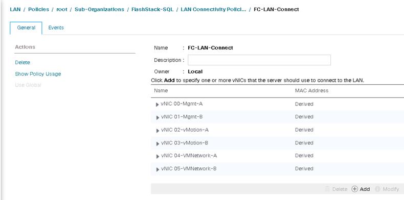
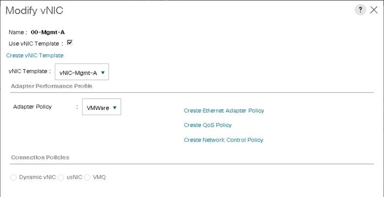
Figure 6 shows applying the default Ethernet VMware policy to the 00-Mgmt-A vNIC. The same adapter policy is used for all six vNICs.
Figure 6. Applying Adapter Policy Using LAN Connectivity Policy
For more information on the VIC tuning options and performance validation, refer to the following links:
The following sections provide steps to configure Cisco UCS templates and polices to enable the ESXi hosts to boot from FC SAN and access the Pure Storage volumes for storing virtual machines.
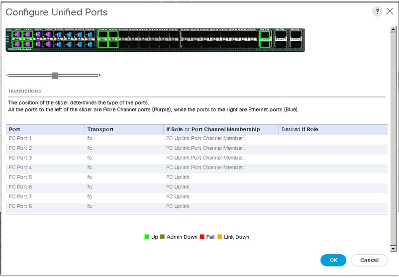
Configure Unified Ports
Cisco UCS 6454 Fabric Interconnects will have a slider mechanism within the Cisco UCS Manager GUI interface that will control the first 8 ports starting from the first port and configured in increments of the first 4 or 8 of the unified ports. In this solution, all 8 ports are enabled but only 4 ports are used for Pure Storage access using the Fibre Channel protocol. The other four ports (5 to 8) are unused and they can be used for future use. Figure 7 shows enabling unified ports on a Fabric Interconnect.
Figure 7. Cisco UCS Unified Port Configuration
Configure VSANs and Fibre Channel Port Channels
For this solution, two VSANS are used, one for each SAN switching fabric. Table 4 lists the VSANs used for this solution.
| VSAN Name |
VSAN ID |
Fabric |
| FlashStack-VSAN-A |
101 |
A |
| FlashStack-VSAN-B |
201 |
B |
The Fibre Channel Port Channel needs to be configured on each Fabric Interconnect with the Unified Ports that were configured previously. Figure 8 shows the Fibre Channel Port Channel created on Fabric A.
Figure 8. Fibre Channel Port Channel on Fabric-A
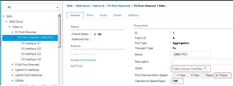
Ensure that the appropriate Port Channel Admin speed is selected, and the aggregated bandwidth is correctly calculated based on the number FC ports that were configured members of the Port Channel.
Table 5 lists the FC Port Channels configured for this solution.
Table 5. Fibre Channel Port Channel
| FC Port Channel Name |
Fabric |
FC Interface Members |
VSAN Name/ID |
Aggregated Bandwidth (Gbps) |
| SAN-PO1 |
A |
1/1, 1/2, 1/3 and 1/4 |
FlashStack-VSAN-A/101 |
128 |
| SAN-PO2 |
B |
1/1, 1/2, 1/3 and 1/4 |
FlashStack-VSAN-B/201 |
128 |
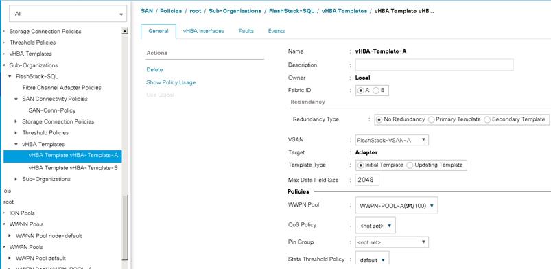
vHBA Templates
The required virtual Host Bus Adapters (vHBAs) are created from the HBA templates. Table 6 lists detailed information about the HBAs templates and vHBAs used for this solution.
Table 6. Fibre Channel vHBA Templates
| vHBA Template Name |
vHBA-Template-A |
vHBA-Template-B |
| Purpose |
FC storage access using Fabric - A |
FC storage access using Fabric – B |
| Settings |
Value |
Value |
| Fabric |
A |
B |
| Redundancy Type |
No Redundancy |
No Redundancy |
| VSAN |
FlashStack-VSAN-A/101 |
FlashStack-VSAN-B/201 |
| Target |
Adapter |
Adapter |
| Template Type |
Initial Template |
Initial Template |
| Max Data Field Size |
2048 |
2048 |
| WWPN Pool |
WWPN-Pool-A |
WWPN-Pool-B |
| QoS Policy |
Not Set |
Not Set |
A sample HBA template for Fabric-A is shown below:
Figure 9. HBA-Template
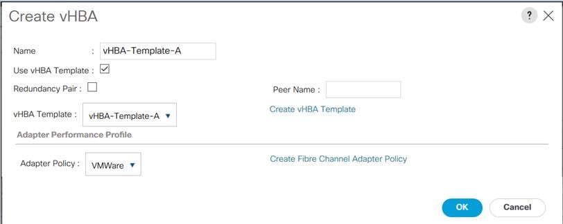
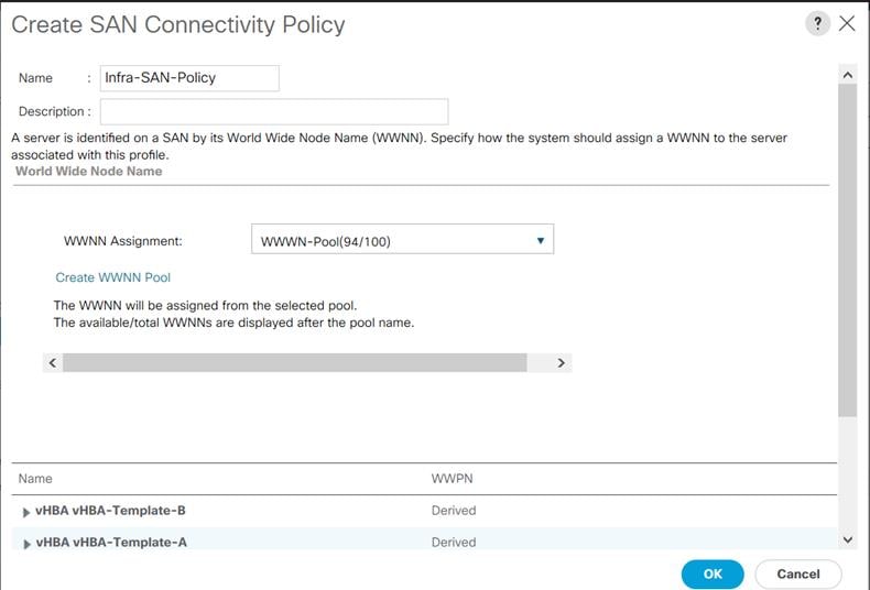
SAN Connectivity Policy
vHBAs are derived from the previously described vHBA templates and added in a specific order in the SAN Connectivity Policy. Figure 10 shows how to derive a vHBA from “vHBA-Template-A” using the SAN Connectivity Policy.
Figure 10. Deriving vHBA From vHBA-Template Using SAN Connectivity Policy
For this solution two vHBAs are used, one for each Fibre Channel Fabric Switching. Figure 11 shows the SAN Connectivity Policy where two vHBAs are derived, one from the vHBA templates.
Figure 11. SAN Connectivity with Two vHBAs
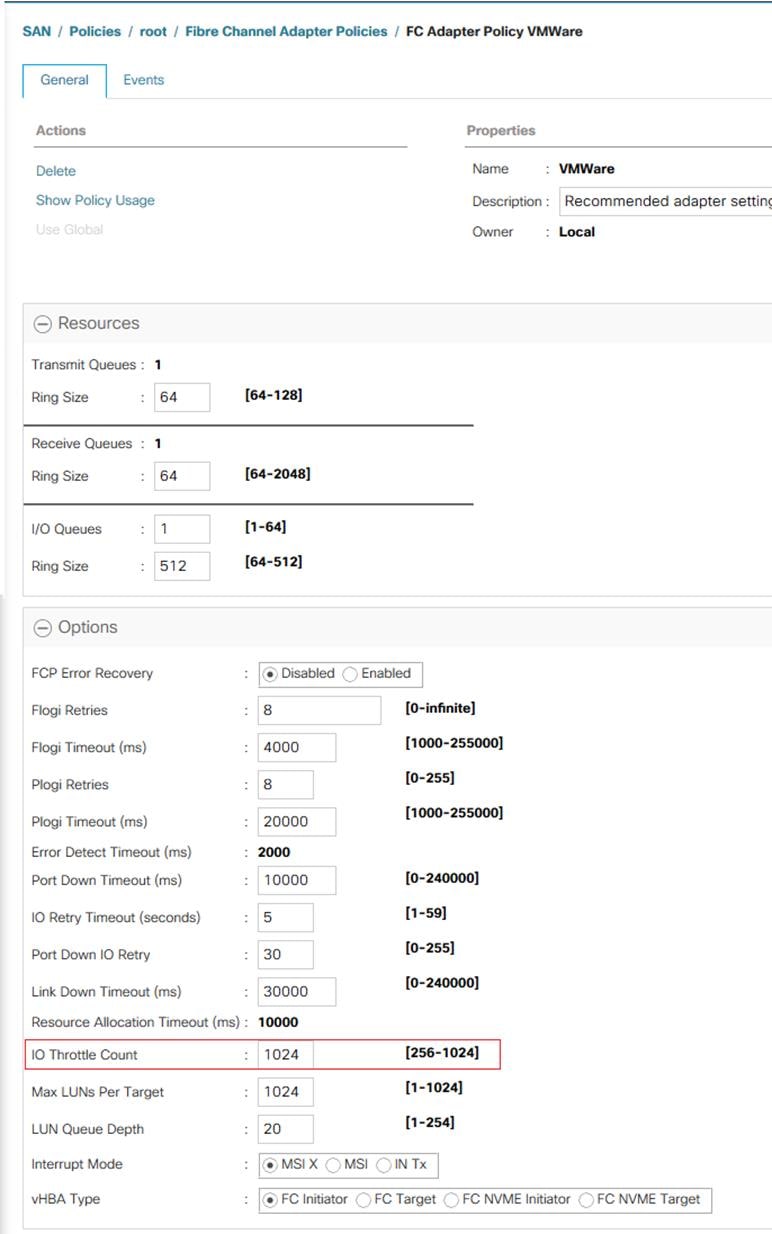
Fibre Channel Adapter Policy
For this solution, the Default VMware Fibre Channel Adapter is used. IO Throttle Count is changed from the default value of 256 to 1024 for higher I/O outstanding requests per virtual host adapter (vHBA).
Figure 12. Fibre Channel Adapter Policy
LUN Queue Depth setting will be changed per datastore at the ESXi hypervisor level from a default value to a higher value. This will be explained in the following sections.
It is recommended to use appropriate BIOS settings on the servers based on the workload they run. The default bios settings work towards power savings by reducing the operating speeds of processors and move the cores to the deeper sleeping states. These states need to be disabled for sustained high performance of database queries. The following BIOS settings are used in our performance tests for obtaining optimal system performance for SQL Server OLTP workloads on Cisco UCS B200 M5 server. The following figure shows some of the settings that are important to consider for optimal performance.
Figure 13. BIOS Policy for Cisco UCS B200 M5 Blade Server
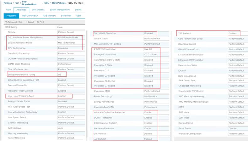
In addition to the above described processor settings, make sure the following BIOS options have been configured as follows:
Click the RAS Memory tab and set LV DDR mode -> Performance mode and Memory RAS Configuration -> Platform Default.
The remaining policies and configuration steps for deploying FlashStack System for hosting the SQL Server virtual machines are described here: https://www.cisco.com/c/en/us/td/docs/unified_computing/ucs/UCS_CVDs/flashstack_6_7_fc_u1.html#_Toc27987010
Cisco MDS Switch Configuration
On each Cisco MDS Switch, you need to configure the required FC port channels, VSANs, zone, zonesets and FC interface. These configurations, except for the FC interface numbers and VSAN numbers, are standard and no different than what is explained in the base infrastructure CVD.
Refer to the Appendix for the Cisco MDS switch configuration used for this solution.
VMware ESXi Host Configuration
This section describes the VMWare ESXi host specific configurations to be implemented on each ESXi host. These changes are required for achieving optimal system performance for SQL Server workloads.
It is assumed that all the infrastructure stacks like network, compute and storage layers are configured correctly and the Cisco UCS B200 M5 blades are able to detect and access the boot LUNs and is ready for ESXi installation.
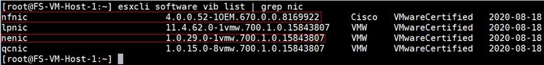
Install VMware Driver for Cisco Virtual Interface card (VIC)
It is always recommended to use latest VIC drivers for the specific vSphere ESXi hypervisor. For the most recent VIC driver versions, refer to: Cisco UCS Hardware & Software Interoperability Matrix. At the time of testing of this solution, the following are the versions of the VIC drivers that were used from the Cisco custom image for VMware vSphere 7.0. It is always recommended to upgrade to the latest version that is available.
Figure 14. ESXi VIC Drivers
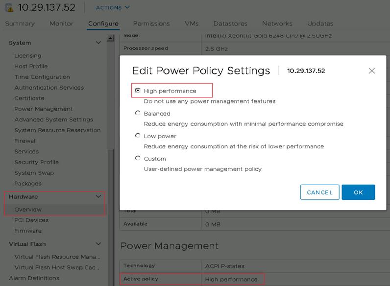
An ESXi host can take advantage of several power management features that the hardware provides to adjust the trade-off between performance and power use. You can control how ESXi uses these features by selecting a power management policy.
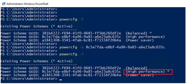
ESXi has been heavily tuned for driving high I/O throughput efficiently by utilizing fewer CPU cycles and conserving power. Hence the Power setting on the ESXi host is set to “Balanced.” However, for critical database deployments, it is recommended to set the power setting to “High Performance.” Selecting “High Performance” causes the physical cores to run at higher frequencies and thereby it will have positive impact on the database performance. The ESXi host power setting is shown in Figure 15.
Figure 15. ESXi Host Power Policy
ESXi Host Networking Configuration
This section provides more information about the ESXi host network configuration for this FlashStack system hosting SQL Server virtual machines.
Note that the Cisco UCS LAN connectivity policy ensures that vNICs are presented to the ESXi in the same order that they are derived in the LAN connectivity policy. Table 7 lists the order in which the vNICs will be mapped to the ESXi host physical adapters.
Table 7. UCSM vNICs to ESXi Physical Adapters Mapping
| vNIC Name |
ESXi Physical Adapter and Speed |
| 00-Mgmt-A |
vmnic0, 20Gbps |
| 01-Mgmt-B |
Vmnic1, 20Gbps |
| 03-vMotion-A |
Vmnic2, 20Gbps |
| 03-vMotion-B |
Vmnic3, 20Gbps |
| 04-VMNetwork-A |
Vmnic4, 20Gbps |
| 05-VMNetwork-B |
Vmnic5, 20Gbps |
In this reference architecture, VMware vSphere Distributed Switches (VDS) are used for a centralized management and monitoring of ESXi hosts and VMs. The following sections provide more information about the Distributed switches, Distributed Port Groups and other settings used for this FlashStack solution. The default ESXi VMkernel port (vmk0) will also be migrated from the Default Standard vSwicth0 to the Distributed Switch.
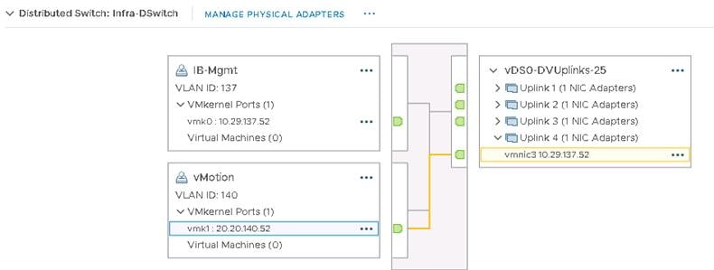
Distributed Switch for ESXi Host Infrastructure Management and vMotion Traffic
Using the first four ESXi Physical adapters (vmnic0 to 3), a dedicated vDS is created for both ESXi host management and vMotion traffic. This vDS is configured with two Distributed Port Groups “IB-Mgmt” and “vMotion”. For ESXi Management traffic, only “Uplink 1” is configured as active uplink and “Uplink 2” as standby uplink. For vMotion traffic, “Uplink 4” is configured as active and “Uplink 3” as configured as standby. This approach enables us to divert the Management and vMotion traffics on two different Fabrics and distributes the load across two Fabrics. Table 8 provides more information about the vDS created for Infrastructure management traffic.
Table 8. vSphere Standard Switch and Port Group Configuration for Infra Management and vMotion Traffic
| Configuration |
Details |
| Switch Name |
Infra-DSwitch |
| Number of physical Adapters (uplinks) |
4 (vmnic0, vmnic1, vmnic2 and vmnic3) |
| MTU Setting |
9000 Port Groups created on this Standard Switch |
| Management Network |
Purpose: For managing and accessing ESXi hosts Active Uplinks: Uplink 1 (vmnic0) Standby Uplinks: Uplink 2 (vmnic1) Unused: Uplink 3 and 4(vmnic2 and 3) VLAN: 137 A VMkernel port (vmk0) is configured with appropriate IP addresses on each ESXI host. MTU on the vmk0 : 1500 |
| vMotion |
Purpose: For virtual machine migration from one ESXi host to other. Active Uplinks: Uplink 4 (vmnic3) Standby Uplinks: Uplink 3 (vmnic2) Unused: Uplink 1 and2 (vmnic0 & 1) VLAN:140 A VMkernel port (vmk1) is configured with appropriate IP addresses on each ESXI host. MTU on the vmk4 : 9000 |
Figure 16 shows the Infra-DSwitch configured with two Port Groups.
Figure 16. ESXi Host Management Network
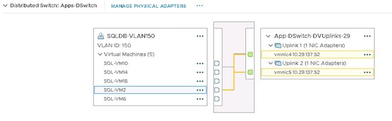
Distributed Switch for SQL Server VMs and Other Application VMs
Using the last two ESXi physical adapters (vmnic4 and 5), a dedicated vDS is created for management access of SQL virtual machines and any other application VMs. This vDS is configured with one Distributed Port Groups “SQLDB-VLAN150” for managing SQL VMs and other application VMs. For this Port Group, both the uplinks are configured as active-active fashion. This setting will help distribute SQL VM traffic across both the fabrics and also provides aggregated network bandwidth for SQL management traffic. Table 9 provides more information about the vDS created for Infrastructure management traffic.
Table 9. vSphere Standard Switch and Port Group Configuration for SQL VM Management Traffic
| Configuration |
Details |
| Switch Name |
Apps-DSwitch |
| Number of physical Adapters (uplinks) |
2 (vmnic4 and vmnic5) |
| MTU Setting |
9000 Port Groups created on this Standard Switch |
| Port Groups created on this Standard Switch |
Purpose: For managing SQL VMs and other application VMs deployed on ESXi Cluster Active Uplinks: Uplink 1 and Uplink 2( vmnic5 and vmnic6) VLAN: 150 |
Figure 17 shows the Apps-DSwitch with a port group configured.
Figure 17. vDS for SQL VMs Management Traffic
Install and Configure Pure Storage Plugin for vCenter vSphere Client
The Pure Storage Plugin for the vSphere Client provides the ability to VMware users to have insight into and control of their Pure Storage FlashArray environments while directly logged into the vSphere Client. The Pure Storage plugin extends the vSphere Client interface to include environmental statistics and objects that underpin the VMware objects in use and to provision new resources as needed.
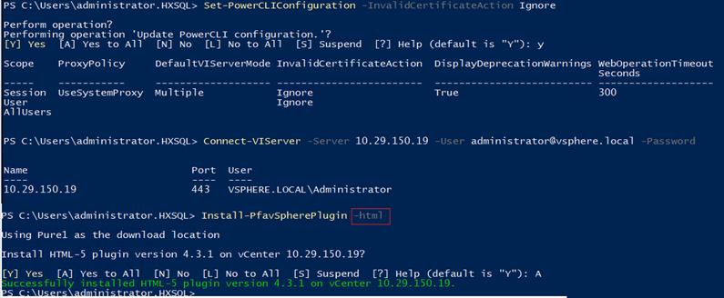
To install the Pure Storage Plugin (HTML version) for vCenter 7.0, follow these steps:
1. Install and load VMware PowerCLI and Pure Storage PowerShell modules on a Windows 2016/2019 client machine by executing following commands. Make sure the client machine has internet access to download the required PowerShell modules:
◦ PS C:\> Install-Module VMware.PowerCLI
◦ PS C:\> Install-Module PureStorage.FlashArray.VMware
◦ PS C:\> Import-Module PureStorage.FlashArray.VMware
◦ PS C:\>Update-Module Purestorage.FlashArray.VMware
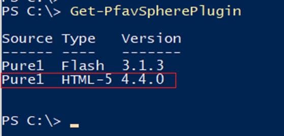
2. After installing Pure Storage FlashArray modules, list the Plugin versions available for installing on the vCenter.
Figure 18. Listing Available FlashArray Plugins
3. For vCenter 7.0, it is recommended to use HTML-5 version of Plugin instead of Flash version for vCenter 7.0. Install the HTML Plugin version as shown below.
Figure 19. Installing Pure FlashArray Plugin
Register Pure Storage FlashArray to vCenter vSphere Client
Once the plugin installed successfully, the Pure Storage plugin is listed under vCenter Home. The next step is to register Pure Storage with the plugin by clicking Add on the plugin UI. Provide the Pure Storage management IP and credentials to register the Pure Storage array in the vCenter as shown below.
Figure 20. Registering Pure FlashArray in vCenter
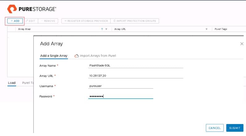
Once the Plugin is registered successfully, the Pure Storage plugin can be used to provision the Pure Storage volumes without logging into the Pure Storage UI.
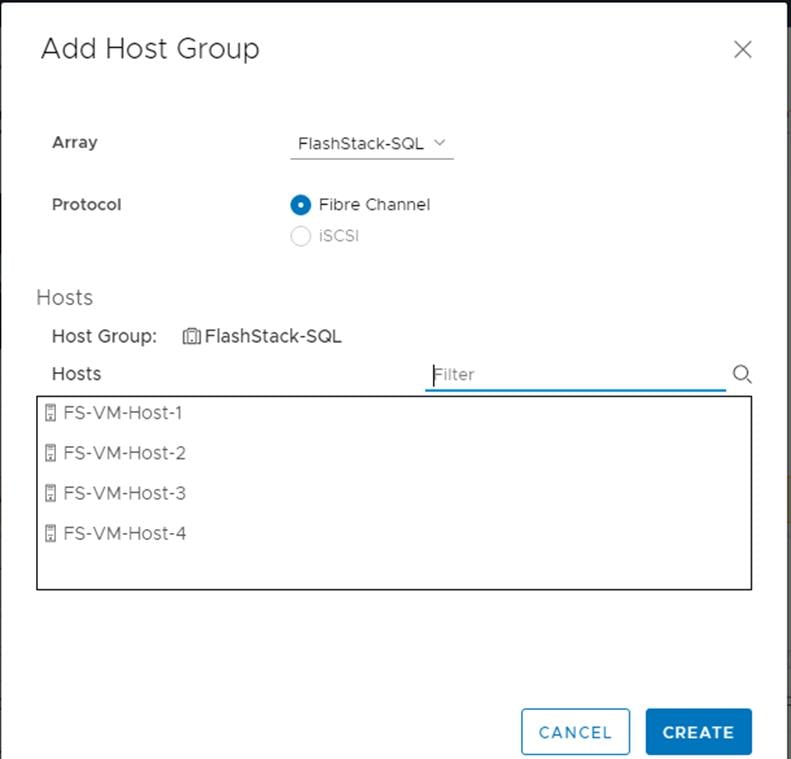
Create Pure Storage Host Groups using Pure Storage Plugin
Multiple ESXi hosts are managed and monitored from the vCenter and form a highly available cluster providing the required compute resources to the VMs. To run the SQL VMs across the ESXi cluster, the Pure Storage volumes need to be shared across all the ESXi hosts. For this purpose, a Host Group is created with all the ESXi hosts as members of the group.
To create a Host Group using Pure Storage Plugin, follow these steps:
1. Log into the vCenter with administrator credentials.
2. Right-click the ESXi cluster -> Pure Storage -> Add Host Group.
3. Select the FlashArray that was added in the previous step.
4. Select Fibre Channel for Protocol.
5. Enter a name for the Host Group.
6. Select ESXi hosts by typing the appropriate text and click Create.
The following figure shows the creation of a Host Group using Pure Storage Plugin.
Figure 21. Creating Host Group using Pure Storage Plugin
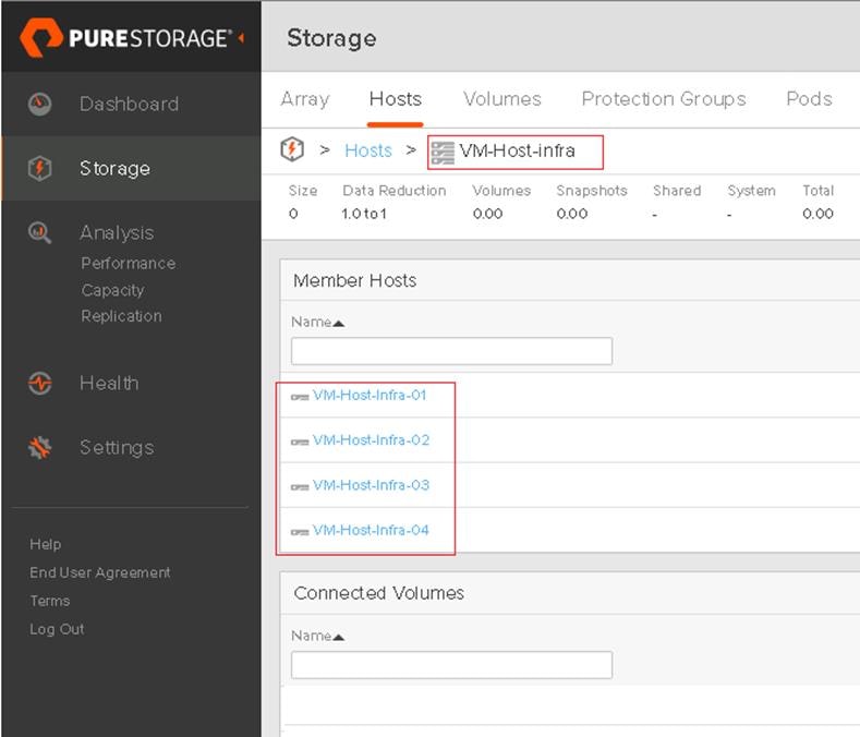
When a Host Group is created within the vCenter using Pure Storage Plugin, a corresponding Host Group will also be created in the Pure Storage FlashArray as shown below.
Figure 22 shows a Host Group created using four ESXi hosts in the Pure Storage.
Figure 22. Pure Storage Host Group for Shared Datastore Access
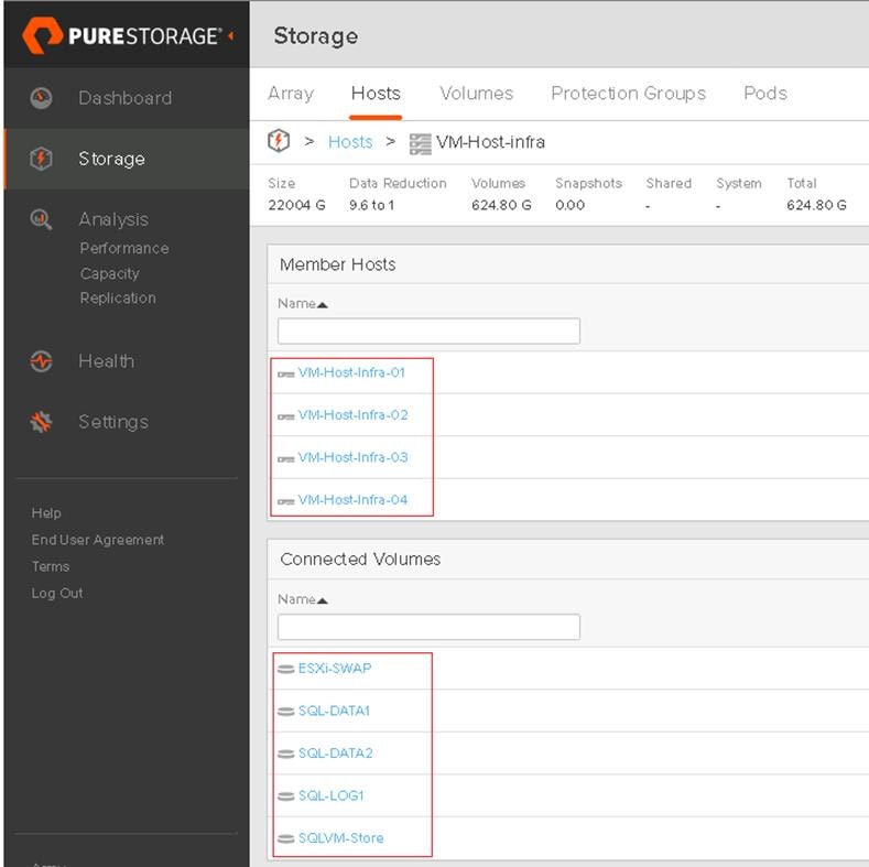
Provision Datastores to ESXi Hosts using Pure Storage Plugin
For storing the SQL Server virtual machines OS files and database files, the following volumes/Datastores are created in the Pure Storage (Table 10).
| Volume Name |
Purpose |
Capacity |
| SQLVM-Store |
For storing OS VMDK files of all the SQL VMs |
2TB |
| ESXi-SWAP |
Used by ESXi hosts for storing swap files of SQL VMs |
500G |
| SQL-DATA1 |
For storing SQL VMs database data files and Tempdb database data files |
5TB |
| SQL-DATA2 |
For storing SQL VMs database data files and Tempdb database data files |
5TB |
| SQL-LOG1 |
For storing SQL VMs database Log files and Tempdb Log data files |
5TB |
The datastores listed in Table 10 are provisioned using the Pure Storage plugin within the vCenter by following these steps:
1. Log into the vCenter with administrator credentials.
2. Right-click the cluster -> Pure Storage -> Create Datastore.
3. Select VMFS as volume type and click Next.
4. Select VMFS version 6 and click Next.
5. Enter the Name of the Datastore and Size of the datastore in GB / TB.
6. Select Your Cluster Name (in this case, FlashStack) to mount the Datastore on all the ESXi hosts.
7. Select the Pure Storage FlashArray on which you are going to create the volume.
8. Select required Protection Group and click Next. Click Next on Volumes groups and QoS.
9. Provide Bandwidth and IOPS Limits on the volumes to impose the QoS on the volumes are the storage level. For Critical SQL Server database deployments, do not restrict any limits on the volumes.
10. Review the summary and click Finish to create the datastore.
11. Repeat steps 1-10 to create the required datastores. These Datastores are created and mounted to all the ESXi hosts and ready to create VMs.
12. When the datastores are created using Pure Storage Plugin, the corresponding volumes will also be created automatically on the Pure Storage FlashArray and added to the Host Group as shown in Figure 23.
Figure 23. Pure Storage Host Group for Shared Datastore Access
Configure LUN Queue Depth on VMFS Datastores Used for Storing SQL Databases
The datastores created in the steps provided in the previous section are used to store and consolidate multiple SQL Server VMs and database files. It is recommended to increase the outstanding IO requests on the datastores where SQL VMs database Data and Log files are stored. By default, the volumes are configured with a default Queue Depth of 32. You can verify the current value by first fetching the parameter of the Cisco nfnic driver module. You can then set the Queue Depth to 128 as shown in Figure 24. You need to reboot the server for the changes to take effect.
Figure 24. Setting Queue Depth on nfnic Driver Module
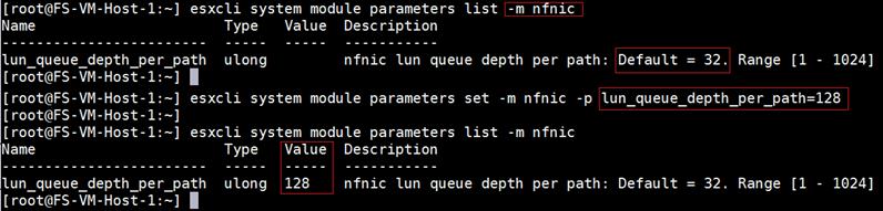
In this solution, SQL-DATA1, SQL-DATA2 and SQL-LOG1 datastores are used for SQL VMs database data and log files.
The Queue Depth value can be set and verified at the individual datastore by supplying the datastore’s naa ID using the following commands. Once set, reboot the server for the change to take effect:
esxcli storage core device set -O 128 -d naa.624a9370ed421e419afe446b0001101e
esxcli storage core device list -d naa.624a9370ed421e419afe446b0001101e | grep -i 'Device Max Queue Depth'
ESXi Native Multipathing Configuration and Adjusting IO Limit
ESXi Round Robin PSP (Path Selection Plug-in) uses a round-robin algorithm to balance the load across all active storage paths. A path is selected and used until a specific quantity of data has been transferred. After that quantity is reached, the PSP selects the next path in the list. The quantity at which a path change triggered is known as the limit. Round Robin defaults to an IOPS limit with a value 1000. In this default case, a new path is used after 1000 I/O operations are issued.
For high-end ESXi clusters driving thousands of IOPS, changing the IOPS limit per active path will result in a slight performance increase as well as quicker path failover (if it is needed).
The IOPS limits can be changed for the required datastores (where SQL database files are stored) by executing the following command. Replace XXXX with first few characters of your naa IDs:
for i in `esxcfg-scsidevs -c |awk '{print $1}' | grep naa.XXXX`; do esxcli storage nmp psp roundrobin deviceconfig set --type=iops --iops=1 --device=$i; done
To verify if the changes are applied, run the command as shown below:
Figure 25. Setting IO Limit
Figure 25 shows the difference of storage path utilizations for the hosts (VM-Host-Infra-01 and 04) on which IOPS limits set to 1 compared to the other hosts (VM-Host-Infra-02 and 03) where the value is not set. As shown, each host has eight active paths to the storage and all the paths are equally utilized for the hosts where IOPS limit set to 1.
Figure 26. Storage Path Utilization with IOPS Limit Set to 1
For more information on changing IOPS limits, please refer to https://kb.vmware.com/s/article/2053145
ESXi Host Logical Network Diagram
Figure 27 shows the logical network diagram of ESXi host depicting Distributed Switches, port groups, VMkernel adapters and Fibre Channel Adapters of a ESXi host described in the previous sections.
Figure 27. ESXi Logical Network Diagram
SQL Server virtual machines are attached to “SQKDB-VLAN150” port group for management access; Multiple virtual disks can be created and attached to SQL Server for storing SQL database files. These virtual disks are created on the distributed Datastores. ESXi hosts get access to these datastores using two vHBAs as shown above.
![]() SQLDB-VLAN150 network is used for both SQL guest management as well as the SQL Server-Client communication. Customers can create additional port groups with the appropriate VLAN to segregate SQL guest management traffic and SQL Server-Client traffic.
SQLDB-VLAN150 network is used for both SQL guest management as well as the SQL Server-Client communication. Customers can create additional port groups with the appropriate VLAN to segregate SQL guest management traffic and SQL Server-Client traffic.
Create and Deploy Virtual Machines for Hosting SQL Server Databases
This section describes the best practices and recommendations to create and deploy SQL Server Virtual Machines on the FlashStack system.
As long as the CPU and memory requirements of a virtual machine is within the single physical socket limits, you do not have to change the default settings of “Cores per Socket.” Only when the CPU and memory requirements of a virtual machine is beyond the single physical socket limits, make sure to equally distribute the CPU and memory resources of the virtual machine across the physical sockets.
Also, be careful when customers are using the SQL Server standard edition which supports lesser of 4-sockets or 24 cores. By default, Cores per Socket is set to one and thereby each vCPU is presented as a virtual socket to the virtual machine. For instance, when you assign 6 vCPUs to a virtual machine, the Guest Operating system will have 6 virtual sockets. While configuring vCPUs for virtual machines running SQL Standard edition, ensure that the virtual sockets do not go beyond 4 by adjusting Cores per Socket appropriately.
SQL Server database transactions are usually CPU and memory intensive. For heavy OLTP database systems, it is recommended to reserve all the memory assigned to the SQL Virtual Machines. This makes sure that the assigned memory to the SQL VM is committed and will eliminate the possibility of ballooning and swapping from happening memory reservations will have little overhead on the ESXi system. For more information about memory overhead, refer to Understanding Memory Overhead.
Figure 28 shows a valid SQL Server Standard Edition virtual machine configuration; only two virtual sockets are configured by adjusting Cores per Socket setting and note that the Memory reservation box is checked.
Figure 28. Cores per Socket and Memory Reservation
It is highly recommended to configure the virtual machine network adaptors with “VMXNET3.” VMXNET 3 is the latest generation of Paravirtualized NICs designed for performance. It offers several advanced features including multi-queue support, Receive Side Scaling, IPv4/IPv6 offloads, and MSI/MSI-X interrupt delivery.
For this solution, each is SQL virtual machine is configured with one network adapters with VMXNET3 as adapter type. This virtual adapter is connected to the “SQLDB-VLAN150” port group for virtual machine management and SQL access.
Paravirtual SCSI Adapters for SQL Server Virtual Machines
For virtual machines with high disk IO requirements, it is recommended to use Paravirtual SCSI (PVSCSI) adapters. PVSCSI controller is a virtualization aware, high-performance SCSI adapter that allows the lowest possible latency and highest throughput with the lowest CPU overhead. It also has higher queue depth limits compared to other legacy controllers. Legacy controllers (LSI Logic SAS, LSI Logic Parallel and so on) can cause bottleneck and impact database performance; therefore, it is not recommended for IO intensive database applications such as SQL server databases.
PVSCSI adapters have a default Queue Depth limit of 64 per device and 256 per adapter. For high capacity with high IO requirements, it is recommended to use multiple database files stored on multiple virtual disks and have those virtual disks distributed across multiple SCSI controller adapters rather than assigning all of the virtual disks to a single SCSI controller. This ensures that the guest VM will access multiple virtual SCSI controllers (four SCSI controllers’ maximum per guest VM), which in turn results in greater concurrency by utilizing the multiple queues available for the four SCSI Adapters.
Table 11 lists the sample SQL VM disk layout used for this solution validation.
| SCSI Con-troller |
Controller Type |
Disk Purpose |
Disk Size(GB) |
Datastore |
| SCSI Controller 1 |
Para Virtual |
OS + SQL Binaries |
60 |
SQLVM-Store |
| SCSI Controller 2 |
Para Virtual |
SQL Server Data Disk 1 (user databases and TempDB data files) |
200 |
SQL-DATA1 |
| SCSI Controller 3 |
Para Virtual |
SQL Server Data Disk 2 ( user databases and TempDB data files) |
200 |
SQL-DATA2 |
| SCSI Controller 4 |
Para Virtual |
SQL Server Log Disk ( user databases and TempDB Log files) |
150 |
SQL-LOG1 |
Install Guest Operating System
This section provides the details about the configuration recommendations for Windows Guest Operating System for hosting SQL Server databases.
For a detailed step-by-step process to install Windows Server 2019 Guest Operating System in the virtual machine, please refer to the VMWare documentation.
![]() When the Windows Guest Operating System is installed in the virtual machine, it is highly recommended to install latest VMware tools as explained here.
When the Windows Guest Operating System is installed in the virtual machine, it is highly recommended to install latest VMware tools as explained here.
The default power policy option in Windows Server 2019 is “Balanced.” This configuration allows Windows Server OS to save power consumption by periodically throttling power to the CPU and turning off devices such as the network cards in the guest when Windows Server determines that they are idle or unused. This capability is inefficient for critical SQL Server workloads due to the latency and disruption introduced by the act of powering-off and powering-on CPUs and devices.
For SQL Server database deployments, it is recommended to set the power management option to “High Performance” for optimal database performance as shown in Figure 29.
Figure 29. Windows Guest Power Settings
Increase PVSCSI Adapter Queue Depth Inside SQL Virtual Machines
Some of the Microsoft SQL Server databases will be relatively large and tend to issue a lot of simultaneous IOs resulting in insufficient device queue depth settings to sustain the heavy IOs. For such database virtual machines, It is recommended to change the default queue depth setting to a higher value (up to 254 per device and 1024 for PVSCSI Adapter) as suggested in this VMware KB article: https://kb.vmware.com/s/article/2053145. Execute the following command on Windows Guest OS using PowerShell and reboot the guest VM for the changes to take effect:
REG ADD HKLM\SYSTEM\CurrentControlSet\services\pvscsi\Parameters\Device /v DriverParameter /t REG_SZ /d "RequestRingPages=32,MaxQueueDepth=254"
NTFS file system with 64K allocation unit size are used for this solution for formatting the disks for storing SQL database files.
Add Windows Guest to AD Domain
It is recommended to change the default Windows Guest VM name and join it to the domain before proceeding with SQL Server installation in the guest virtual machine. For detailed instructions about how to change the Guest name and join the Guest, click here.
Using the server manager, enable the Remote Desktop feature to manage the Guest VM remotely and make sure to enable 1433 port for accessing SQL Server by the clients or other applications.
Install SQL Server and Configuration Recommendations
There are many recommendations and best practices guides available for most of SQL Server settings. But the relevance of these recommendations may vary from one database deployment to another. It is recommended to thoroughly test and validate the critical settings and determine whether or not to implement the specific database environment. The following sections describe some of the key aspects of the SQL Server installation and configurations, which have been used and tested on the FlashStack system. The rest of the SQL Server settings are kept at default and used for performance testing.
Microsoft SQL Server 2019 Installation
This section provides a high-level installation process. For the detailed step-by-step installation for SQL Server 2019 on a Windows Operating system, refer to the Microsoft document: Install SQL Server from the Installation Wizard (Setup).
1. On the Server Configuration window of SQL Server installation, make sure that the instant file initialization is enabled by enabling the checkbox as shown below. This makes sure the SQL server data files are instantly initialized avowing zeroing operations.
Figure 30. Enabling Instant File Initialization of Database Files
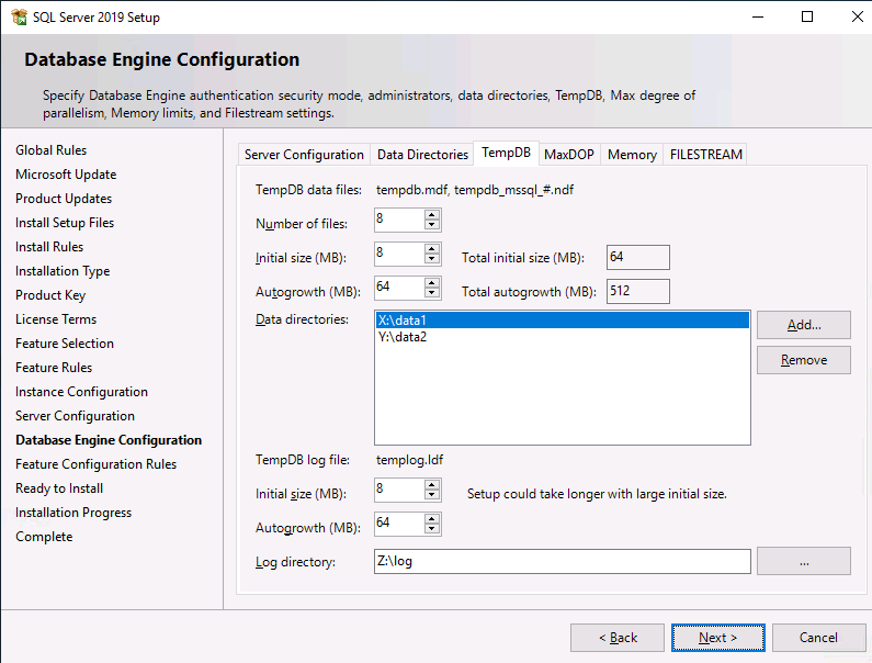
2. In the Database Engine Configuration window under the TempDB tab, make sure the number of TempDB data files are equal to 8 when the vCPUs or logical processors of the SQL VM is less than or equal to 8. If the number of logical processors is more than 8, start with 8 data files and try to add data files in the multiple of 4 when the contention is noticed on the TempDB resources. The following diagram shows that there are 8 TempDB files chosen for a SQL virtual machine which has 8 vCPUs. Also, as a best practice, make sure the TempDB data and log files are two different volumes. For more details on TempDB configuration, refer: https://docs.microsoft.com/en-us/sql/relational-databases/databases/tempdb-database?view=sql-server-ver15
Figure 31. TempDB Files Configuration
Enable Lock Pages in Option Memory for SQL Server
To enable the lock pages, follow these steps:
1. Make sure to add SQL Server service account is added to “Lock Pages in Memory” policy using the Windows Group Policy editor. Granting the Lock pages in memory user the right to the SQL Server service account prevents SQL Server buffer pool pages from paging out by the Windows Server.
Figure 32. Enabling Lock Pages In Memory Option For SQL Server
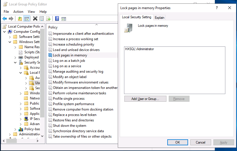
2. A domain account is used as a SQL Server service account which is not a member of the local administrator group, then add SQL Server service account to the “Perform volume maintenance tasks” policy using the Local Security Policy editor.
Max Memory Setting
The SQL Server can consume all the memory allocated to the VM. Setting the Maximum Server Memory allows you to reserve sufficient memory for Operating System and other processes running on the VM. Ideally, you should monitor the overall memory consumption of SQL Server under regular business hours and determine the memory requirements. To start, allow the SQL Server to consume about 80 percent of the total memory or leave at least 2-4GB memory for Operating system. The Maximum Server Memory setting can be dynamically adjusted based on the memory requirements.
Database files and their sizes
For user databases that have heavy DML operations, it is recommended to create multiple data files of the same size in order to reduce the allocation contention. For the production deployments, configure data and log files as big as possible to avoid file expansion during a production operation.
If there are high IO demanding workload deployments, use more than one volume for keeping the database data files. The database performance of such deployments may hit by the queues depths defined at the volume level both in ESXi environment as well storage level.
For additional SQL Server configuration recommendations, refer to the following:
VMware Architecting Microsoft SQL Server on VMware vSphere® Best Practices Guide
Solution Performance Testing and Validation
This section describes the tests conducted to validate the robustness of the solution. Table 12 lists the complete details of the testbed setup used for conducting various performance tests discussed in the following sections.
Table 12. Hardware and Software details of Testbed Configuration
| Component |
Device Details |
| Compute |
1x Cisco UCS 5108 blade chassis with 2x Cisco UCS 2408 IO Modules 4x Cisco UCS B200 M5 blades each with one Cisco UCS 1440 VIC adapter |
| Processor Cores per Cisco UCS B200 M5 blade |
2x Intel® Xeon® Gold 6248 CPUs, 2.5GHz, 27.5MB L3 cache, 20 Cores per CPU |
| Memory per Cisco UCS B200 M5 blade |
384GB (12x 32GB DIMMS operating at 2933MHz) |
| Fabric Interconnects |
2x Cisco UCS 4th Gen 6454 Cisco UCS Manager Firmware: 4.1(1C) |
| Network Switches |
2x Cisco Nexus 9336C-FX2 switches |
| Storage Fabric Switches |
2x Cisco MDS 9132T Switches |
| Storage Controllers |
2x Pure Storage FlashArray//X50 R3 with 20 x 1.92 TB NVMe SSDs |
| Hypervisor |
VMWare vSphere 7.0 |
| Guest Operating System |
Windows 2019 Standard Edition |
| Database software |
SQL Server 2019 Enterprise Edition CU 6 |
| Testing tool used for SQL Database performance validation |
DVD Store 3.0 (DS3) |
Performance Test Methodology and Results
In this reference architecture, the FlashStack system is tested and validated with Microsoft SQL Server databases for OLTP (Online Transaction Processing) workloads. Typically, the OLTP workloads are compute-intensive and characterized by a large number of parallel random reads and writes. The FlashStack system, which is built with the combination of Cisco UCS B200 M5 blade servers powered by the latest Intel 2nd Generation scalable processors, 25/100G Fabric Interconnects, Cisco Nexus switches, Cisco MDS Fibre Channel switches and Pure Storage FlashArray storage, enable customers to seamlessly consolidate and run many SQL Server databases instances.
This reference architecture demonstrates three aspects of the FlashStack system by hosting multiple SQL server OLTP-like workloads. The following list provides the tests conducted on the FlashStack system:
● Demonstrate database performance scalability for both scale-up and scale-out scenarios using a single Cisco UCS B200 M5 blade server and multiple Cisco UCS B200 M5 blade servers for a 100G database.
● Demonstrate IO capacity of the Pure FlashArray//X50 R3 storage array.
The DVD store tool is used to simulate an OLTP-like workload on each SQL Server database VM running on the FlashStack system. This tool is installed on a separate client machine and multiple driver instances of the tool ran to simulate OLTP like workload against SQL Server virtual machines running on the FlashStack system. At the end of each test, the tool reports performance metrics such as Orders Per Min (OPM), response time, and so on.
Database Performance Scalability within Single Cisco UCS B200 M5 ESXi Host
The objective of this test is to demonstrate how a single Cisco UCS B200 M5 host can respond as more SQL workload VMs are added to the host.
Table 13 lists the virtual machine configuration and database schema details used for this test. Each virtual machine is configured with 8 vCPUs and 10GB memory. Each SQL VM is stressed at about 70-75 percent of the guest CPU utilization.
Table 13. Virtual Machine Configuration Used for Single Cisco UCS B200 Scalability Test
| Component |
Device Details |
| VM Configuration |
6 vCPUs, 10GB Memory (8GB allocated for SQL) |
| Storage Volumes for database |
2 x 200G disk for user database and TempDB data files 1 x 150GB disk for user database and TempDB T-LOG file |
| Database |
Microsoft SQL Server 2019 Enterprise Edition CU 6 |
| Operating System |
Windows 2019 Standard Edition |
| Workload per VM |
Database Size: 100GB Guest CPU utilization: ~70 -75% Performance Metrics collected: Orders Per Minute (OPM) from DVD store Windows Perfmon IO metrics ESXi ESXTOP metrics |
Figure 33 shows how multiple SQL Server virtual machines perform on a single ESXi host. As shown, a single SQL virtual machine delivered about 8300 DVD Orders Per Min (OPM) and response time ranged between 100ms to 110ms . As more SQL virtual machines are added to the same host (up to 5 VMs), the OPM has scaled linearly as there are no bottlenecks discovered within the Cisco UCS B200 M5 host and also Pure Storage FlashArray was able to deliver the required IOPS. As more virtual machines are added to the host, proportional CPU utilization of the underlying Cisco UCS B200 M5 host has also scaled linearly as shown in below. ESXi host CPU utilization of two, three, four and five VMs is 1.9, 2.8, 3.8 and 4.8 times respectively, as compared to Single VM’s ESXi CPU utilization.
Figure 33. Database Performance Scalability with Single Cisco UCS B200 M5 ESXi Host
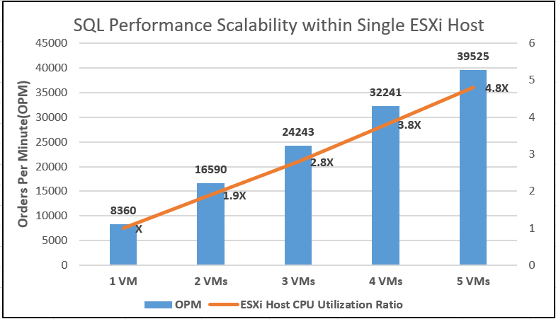
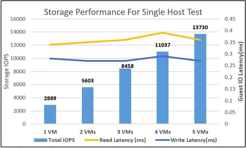
Figure 34 shows the disk data transfers (IOPS) and latency details for this test. The performance numbers are captured using ESXTOP utility. As shown, as more SQL virtual machines are added to the same host, the IOPS scaled almost linearly. The ESXTOP Guest latencies stayed under 0.4 milliseconds.
Figure 34. IOPS Scalability with Single Cisco UCS B200 M5 ESXi Host
Database Performance Scalability Across the Four Node ESXi Cluster
The objective of this test is to demonstrate the database performance scalability when multiple SQL VMs are deployed across a four-node ESXi cluster, which is typically seen in real-world implementations.
For this multi-hosts testing, the same virtual machine configuration and database schema that is used in the single ESXi Host testing is retained.
Figure 35 shows four SQL virtual machines spread across the cluster that delivered about 33400 Orders per Minute and response times ranged from 100 to 110ms. As more SQL virtual machines are added to the cluster (up to 16 VMs, 4 VMs per Host), the OPM is scaled almost linearly as there are no bottlenecks discovered both at compute and storage levels. Also, as virtual machines are added across the ESXi cluster, CPU utilization of the cluster also scaled near-linearly as shown below. ESXi cluster CPU utilization of 8, 12 and 16 VMs is 2, 2.9, and 3.8 times respectively, as compared to 4 VM’s.
Figure 35. Database Performance Scalability Across ESXi Cluster
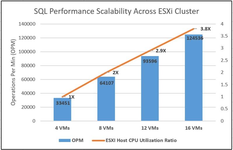
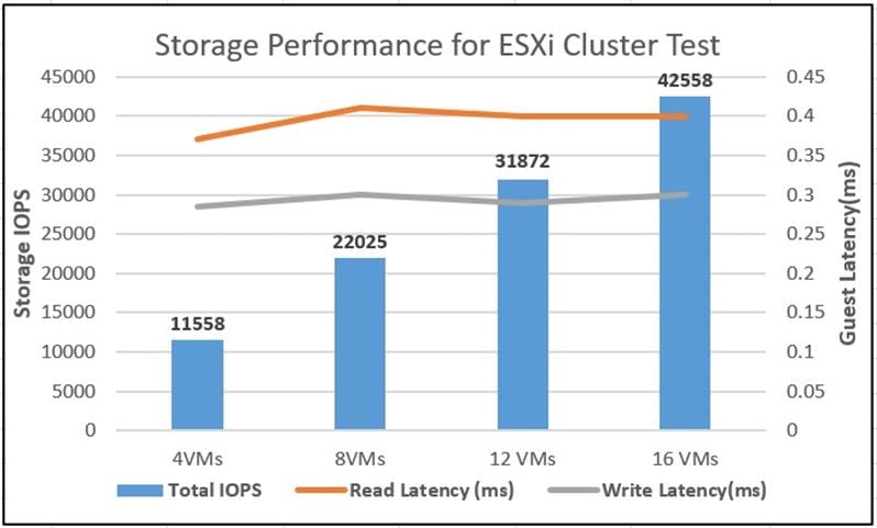
Figure 36 shows the disk data transfers (IOPS) and latency details for this test. As more SQL virtual machines are added to the cluster (up to 16 VMs), the IOPS scaled near-linearly. The IO latencies stayed less than 0.4 milliseconds.
Figure 36. IOPS Scalability Across ESXi Cluster
IO Stress Test of Pure Storage FlashArray//X50 R3 for SQL Database Workload
The goal of this test is to demonstrate how Pure FlashArray//X50 R3 would behave under high IO stress generated by SQL Server OLTP workload VMs.
One of the ways to stress the storage is to reduce the available memory to SQL Server so all of the database IO operations will land on storage array due to limited SQL buffer cache. Table 14 lists the VM configuration used for this test.
Table 14. Virtual Machine Configuration for Pure FlashArray//X50 R3 Maximum Storage Performance Test
| Component |
Device Details |
| VM Configuration |
6 vCPUs, 6GB Memory (4GB allocated for SQL) |
| Storage Volumes for database |
2 x 200G volumes for user database and TempDB data files 1 x 150GB volume for user database and TempDB for T-LOG file |
| Database |
SQL Server 2019 Evaluation Edition |
| Operating System |
Windows 2019 Standard Edition |
| Workload per VM |
Database Size: 100GB |
For this test, 20 SQL virtual machines are deployed across the four node ESXi cluster. SQL Server databases are stressed using the DVD store tool running from separate client machines. The following graph shows the storage metrics collected using Pure1 manager during the test. Each SQL virtual machines is stressed up to its 65-70 percent CPU utilization using 10 DVD store users contributing to 8000 to 9000 IOPS resulted in a total of 180,000 IOPS at under 0.5ms:
Figure 37. Pure FlashArray//X50 R3 Storage System Maximum IOPS Test
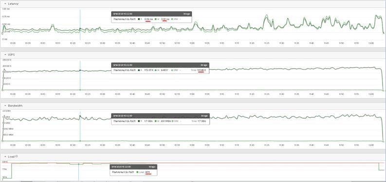
As shown above, the storage array CPU was near 95 percent, which indicates that the storage system is at or near its maximum capability. While the system could support additional workload that would drive CPU utilization even higher, Pure recommends that storage systems operate below 80 percent utilization during normal operations to prevent significant performance impact during a controller failure scenario.
For more storage capacity, more disk enclosures can be added to the existing controllers. However, for more IO performance with the same level of latencies, new pair of FlashArray controllers needs to be added.
Infrastructure Management with Cisco Intersight
Cisco Intersight™ is a cloud-based infrastructure management platform delivered as a service with embedded analytics for your Cisco and 3rd party IT infrastructure. This platform offers an intelligent level of management that enables IT organizations to analyze, simplify, and automate their environments which are geographical dispersed across the world through a single pane of management interface.
For more information about Cisco Intersight, refer to:
https://intersight.com/help/features
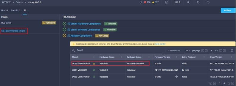
In addition to the hardware inventory listing, monitoring and management, Cisco Intersight includes a Cisco driver check against the Cisco Hardware Compatibility List (HCL). It validates Operating System/Hypervisor versions, hardware firmware and driver versions against the Cisco supported versions for each Cisco UCS platform and provides recommendation if there are any non-compliance issues. One can quickly review the recommendations and take the necessary actions to make them compliant. The following figure shows the Cisco VIC drivers are not up to date. Click “Get Recommended Drivers” link to view the recommended compatible driver versions.
Figure 38. Intersight Validating Cisco UCS B200 M5 Hardware Compatibility
Pure Storage and vSphere Integration with Cisco Intersight
Cisco Intersight supports management and monitoring of third party infrastructures such as VMware vSphere clusters and Pure Storage FlashArray. These third-party devices are integrated into Cisco Intersight using a virtual appliance called “Intersight Assist.” Refer to the following links to deploy Intersight Assist Virtual Appliance and integrate the Pure Storage FlashArray and vCenter:
https://www.youtube.com/watch?v=_HSUNCZ2HmY
![]() The purpose of this section is to explain the integration of Pure Storage and VMware vCenter with Cisco Intersight and highlight some of the capabilities and features that are available in the tech preview mode which is suitable for low risk development and test environments only.
The purpose of this section is to explain the integration of Pure Storage and VMware vCenter with Cisco Intersight and highlight some of the capabilities and features that are available in the tech preview mode which is suitable for low risk development and test environments only.
Pure Storage is the first third-party storage infrastructure integrated into Cisco Intersight. The software and hardware components of Pure Storage FlashArray are presented to Cisco Intersight as objects. Figure 39 shows the details of various objects of Pure Storage FlashArray that are being managed by Cisco Intersight. The General tab shows the high-level details of Pure FlashArray; model, Purity software version, storage capacity utilization reports and the data optimization ratios, and so on.
Figure 39. General view of Pure Storage in Cisco Intersight
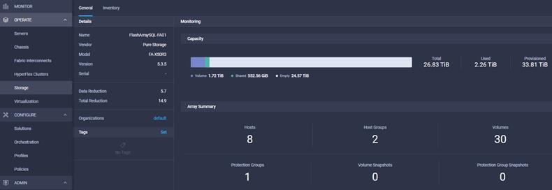
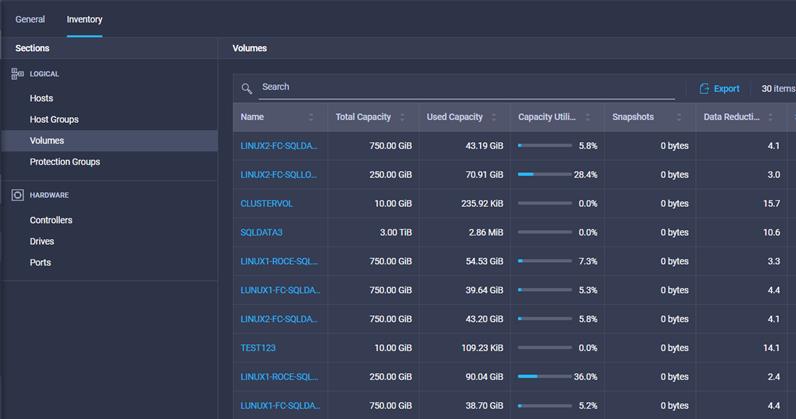
Figure 40 shows the Pure Storage Flash Array software and hardware inventory objects such as Hosts, Host Groups, Volumes, Controllers, Disks, and Ports, and so on.
Figure 40. Pure Storage FlashArray Inventory Details in Cisco Intersight
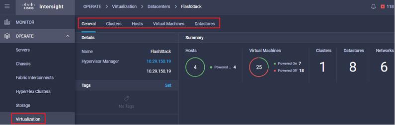
VMware vSphere clusters can also be monitored and managed from Cisco Intersight through the Intersight Assist appliance. Figure 41 shows the vSphere clusters inventory details in Cisco Intersight.
Figure 41. VMware vSphere Cluster Details in Cisco Intersight
Cisco Intersight provides an orchestration engine to build workflows to automate some of the typical datacenter administration tasks. A workflow stitches together the components of various devices in a particular sequence to accomplish a particular task. For example, Figure 42 shows a workflow designed to create a volume on Pure Storage, assign the volume to a host or host group, carve out vSphere datastores with VMFS file system, and finally create a virtual machine using a VM template on the newly created datastore.
Figure 42. Cisco Intersight Workflow
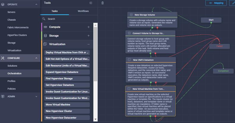
As shown in Figure 42, using the in-built tasks and/or pre-defined workflows, many other datacenter related tasks can be created and automated.
FlashStack is the optimal shared infrastructure foundation to deploy a variety of IT workloads. The solution discussed in this document is built on the latest hardware and software components to take maximum advantages of both UCSM compute and Pure Storage for deploying performance sensitive workloads such as Microsoft SQL Server databases. This CVD is a detailed guide for a Microsoft SQL Server 2019 deployment on Windows Server 2019 virtual machines that are deployed in VMware virtual environments. The performance tests detailed in this document prove the robustness of the solution.
FlashStack Virtual Server Infrastructure with Fibre Channel Storage for VMware 6.7:
https://www.cisco.com/c/en/us/td/docs/unified_computing/ucs/UCS_CVDs/flashstack_6_7_fc_u1.html
FlashStack Virtual Server Infrastructure Design Guide For VMware vSphere 6.7
Cisco UCS fNIC Tuning Guide:
Achieve Optimal Network Throughput on the Cisco UCS Virtual Interface Card 1457:
Cisco Compatibility Matrix:
https://ucshcltool.cloudapps.cisco.com/public/
Pure Storage FlashArray //X:
https://www.purestorage.com/content/dam/pdf/en/datasheets/ds-flasharray-x.pdf
Pure Storage FlashArray VMware Best Practices:
Cisco UCS Manager and Cisco UCS Fabric Interconnects 6454:
https://www.cisco.com/c/en/us/products/servers-unified-computing/ucs-manager/index.html
Cisco UCS 2408 Fabric Extender:
Cisco UCS B200 M5 Blade Server and Cisco VIC 1440:
Cisco Nexus 9336C-FX2 Switch:
https://www.cisco.com/c/en/us/support/switches/nexus-9336c-fx2-switch/model.html
Cisco MDS 9132T Fibre Channel Switch:
Gopu Narasimha Reddy, Technical Marketing Engineer, Compute Systems Product Group, Cisco Systems, Inc.
Gopu Narasimha Reddy is a Technical Marketing Engineer in the Cisco UCS Datacenter Solutions group. Currently, he is focusing on developing, testing, and validating solutions on the Cisco UCS platform for Microsoft SQL Server databases on Microsoft Windows and VMware platforms. He is also involved in publishing TPC-H database benchmarks on Cisco UCS servers. His areas of interest include building and validating reference architectures, development of sizing tools in addition to assisting customers in SQL deployments.
Sanjeev Naldurgkar, Technical Marketing Engineer, Compute Systems Product Group, Cisco Systems, Inc.
Sanjeev has been with Cisco for eight years focusing on delivering customer-driven solutions on Microsoft Hyper-V and VMware vSphere. He has over 18 years of experience in the IT Infrastructure, server virtualization, and cloud computing. He holds a bachelor’s degree in Electronics and Communications Engineering and leading industry certifications from Microsoft and VMware.
For their support and contribution to the design, validation, and creation of this Cisco Validated Design, the authors would like to thank:
● Babu Mahadevan, Cisco Systems, Inc
● John McAbel, Cisco Systems, Inc.
● Vijay Durairaj, Cisco Systems, Inc.
● Hardik Kumar Vyas, Cisco Systems, Inc.
● Craig Walters, Pure Storage
● Argenis Fernandez, Pure Storage
● Mike Nelson, Pure Storage
● Lori Brooks, Pure Storage
Appendix: Cisco Nexus and MDS Configuration
Cisco Nexus C9336C-FX2 Switch Configuration
Cisco Nexus C9336C-FX2-A and B
feature udld
feature interface-vlan
feature lacp
feature vpc
feature lldp
system default switchport
no system default switchport shutdown
spanning-tree port type network default
spanning-tree port type edge bpduguard default
spanning-tree port type edge bpdufilter default
port-channel load-balance src-dst l4port
ntp server 72.163.32.44 use-vrf management
ntp master 3
vlan 137
name IB-MGMT-VLAN
vlan 140
name vMotion-VLAN
vlan 150
name VMNetwork-VLAN
Cisco Nexus C9336C-FX2-A only:
vpc domain 10
peer-switch
role priority 10
peer-keepalive destination 10.29.137.7 source 10.29.137.6 vrf management
peer-gateway
delay restore 150
auto-recovery
ip arp synchronize
Cisco Nexus C9336C-FX2-B only:
vpc domain 10
peer-switch
role priority 20
peer-keepalive destination 10.29.137.6 source 10.29.137.7 vrf management
delay restore 150
peer-gateway
auto-recovery
ip arp synchronize
Cisco Nexus C9336C-FX2-A and B:
interface ethernet 1/1-2
switchport mode trunk
switchport trunk allowed vlan 137,140,150,160,170
channel-group 100 mode active
no shutdown
interface port-channel 10
description Nexus-vPC-100-PeerLink
mtu 9216
vpc peer-link
Cisco Nexus C9336C-FX2-A and B
interface ethernet 1/31
switchport mode trunk
switchport trunk allowed vlan 137,140,150,160,170
channel-group 101 mode active
no shutdown
interface port-channel 101
description UCS-6454-A-vPC101
mtu 9216
vpc 101
interface ethernet 1/32
switchport mode trunk
switchport trunk allowed vlan 137,140,150,160,170
channel-group 102 mode active
no shutdown
interface port-channel 102
description UCS-6454-B-vPC102
mtu 9216
vpc 102
copy r s
Cisco MDS-9132T-A Configuration
The following is the MDS-9231T-A configuration:
feature npiv
feature fport-channel-trunk
interface port-channel 101
channel mode active
switchport speed auto
no shutdown
exit
vsan database
vsan 101
vsan 101 name FS-Fabric-A
exit
zone smart-zoning enable vsan 101
vsan database
vsan 101 interface fc 1/17-20
vsan 101 interface port-channel 101
exit
interface fc1/17
switchport description Pure.CT0.FC0
switchport trunk mode off
port-license acquire
no shutdown
interface fc1/18
switchport description Pure.CT1.FC0
switchport trunk mode off
port-license acquire
no shutdown
interface fc1/19
switchport description Pure.CT0.FC2
switchport trunk mode off
port-license acquire
no shutdown
interface fc1/20
switchport description Pure.CT1.FC2
switchport trunk mode off
port-license acquire
no shutdown
interface fc1/21
switchport description UCS6454-A-1/1
port-license acquire
channel-group 101 force
no shutdown
interface fc1/22
switchport description UCS6454-A-1/2
port-license acquire
channel-group 101 force
no shutdown
interface fc1/23
switchport description UCS6454-A-1/3
port-license acquire
channel-group 101 force
no shutdown
interface fc1/24
switchport description UCS6454-A-1/4
port-license acquire
channel-group 101 force
no shutdown
copy running-config startup-config
zone smart-zoning enable vsan 101
zone name Infra-Pure-Fabric-A vsan 101
member device-alias VM-Host-Infra-01-A init
member device-alias VM-Host-Infra-02-A init
member device-alias VM-Host-Infra-03-A init
member device-alias VM-Host-Infra-04-A init
member device-alias Pure-CT0-FC0 target
member device-alias Pure-CT1-FC0 target
member device-alias Pure-CT0-FC2 target
member device-alias Pure-CT1-FC2 target
exit
zoneset name Pure-Fabric-A vsan 101
member Infra-Pure-Fabric-A
exit
zoneset activate name Pure-Fabric-A vsan 101
show zoneset active
copy r s
Cisco MDS-9132T-B Configuration
The following is the MDS-9231T-B configuration:
feature npiv
feature fport-channel-trunk
interface port-channel 201
channel mode active
switchport speed auto
no shutdown
exit
vsan database
vsan 201
vsan 201 name FS-Fabric-B
exit
zone smart-zoning enable vsan 201
vsan database
vsan 201 interface fc 1/17-20
vsan 201 interface port-channel 201
exit
interface fc1/17
switchport description Pure.CT0.FC1
switchport trunk mode off
port-license acquire
no shutdown
interface fc1/18
switchport description Pure.CT1.FC1
switchport trunk mode off
port-license acquire
no shutdown
interface fc1/19
switchport description Pure.CT0.FC3
switchport trunk mode off
port-license acquire
no shutdown
interface fc1/20
switchport description Pure.CT1.FC3
switchport trunk mode off
port-license acquire
no shutdown
interface fc1/21
switchport description UCS6454-B-1/1
port-license acquire
channel-group 201 force
no shutdown
interface fc1/22
switchport description UCS6454-B-1/2
port-license acquire
channel-group 201 force
no shutdown
interface fc1/23
switchport description UCS6454-B-1/3
port-license acquire
channel-group 201 force
no shutdown
interface fc1/24
switchport description UCS6454-B-1/4
port-license acquire
channel-group 201 force
no shutdown
copy running-config startup-config
zone smart-zoning enable vsan 201
zone name Infra-Pure-Fabric-B vsan 201
member device-alias VM-Host-Infra-01-B init
member device-alias VM-Host-Infra-02-B init
member device-alias VM-Host-Infra-03-B init
member device-alias VM-Host-Infra-04-B init
member device-alias Pure-CT0-FC1 target
member device-alias Pure-CT1-FC1 target
member device-alias Pure-CT0-FC3 target
member device-alias Pure-CT1-FC3 target
exit
zoneset name Pure-Fabric-B vsan 201
member Infra-Pure-Fabric-B
exit
zoneset activate name Pure-Fabric-B vsan 201
show zoneset active
copy r s
For comments and suggestions about this guide and related guides, join the discussion on Cisco Community at https://cs.co/en-cvds.