- Preface
- Configuration Overview
- Using the Command-Line Interface
- Configuring Switch Alarms
- Performing Switch Setup Configuration
- Configuring Cisco IOS Configuration Engine
- Configuring Switch Clusters
- Performing Switch Administration
- Configuring Switch-Based Authentication
- Configuring IEEE 802.1x Port-Based Authentication
- Configuring Web-Based Authentication
- Configuring Interface Characteristics
- Configuring Smartports Macros
- Configuring VLANs
- Configuring VTP
- Configuring Voice VLAN
- Configuring STP
- Configuring MSTP
- Configuring Optional Spanning-Tree Features
- Configuring Resilient Ethernet Protocol
- Configuring FlexLinks and the MAC Address-Table Move Update
- Configuring DHCP
- Configuring Dynamic ARP Inspection
- Configuring IP Source Guard
- Configuring IGMP Snooping and MVR
- Configuring Port-Based Traffic Control
- Configuring SPAN and RSPAN
- Configuring LLDP, LLDP-MED, and Wired Location Service
- Configuring CDP
- Configuring UDLD
- Configuring RMON
- Configuring System Message Logging
- Configuring SNMP
- Configuring Network Security with ACLs
- Configuring Standard QoS
- Configuring Auto-QoS
- Configuring EtherChannels
- Configuring Static IP Unicast Routing
- Configuring IPv6 Host Functions
- Configuring Link State Tracking
- Configuring IPv6 MLD Snooping
- Configuring Cisco IOS IP SLAs Operations
- Troubleshooting
- Working with the Cisco IOS File System, Configuration Files, and Software Images
- Finding Feature Information
- Restrictions for Configuring Link State Tracking
- Information About Configuring Link State Tracking
- Link State Tracking
- How to Configure Link State Tracking
- Monitoring and Maintaining Link State Tracking
- Configuration Examples for Configuring Link State Tracking
- Additional References
Configuring Link State Tracking
Finding Feature Information
Your software release may not support all the features documented in this chapter. For the latest feature information and caveats, see the release notes for your platform and software release.
Use Cisco Feature Navigator to find information about platform support and Cisco software image support. To access Cisco Feature Navigator, go to http://www.cisco.com/go/cfn. An account on Cisco.com is not required.
Restrictions for Configuring Link State Tracking
•![]() To use this feature, the switch must be running the LAN Base image.
To use this feature, the switch must be running the LAN Base image.
•![]() An interface that is defined as an upstream interface cannot also be defined as a downstream interface in the same or a different link state group. The reverse is also true.
An interface that is defined as an upstream interface cannot also be defined as a downstream interface in the same or a different link state group. The reverse is also true.
•![]() An interface cannot be a member of more than one link state group.
An interface cannot be a member of more than one link state group.
•![]() You can configure only two link state groups per switch.
You can configure only two link state groups per switch.
Information About Configuring Link State Tracking
Link State Tracking
Link state tracking, also known as trunk failover, is a feature that binds the link state of multiple interfaces. For example, link state tracking provides redundancy in the network when used with server NIC adapter teaming. When the server network adapters are configured in a primary or secondary relationship known as teaming, if the link is lost on the primary interface, connectivity is transparently changed to the secondary interface.

Note ![]() An interface can be an aggregation of ports (an EtherChannel), a single physical port in access or trunk mode, or a routed port.
An interface can be an aggregation of ports (an EtherChannel), a single physical port in access or trunk mode, or a routed port.
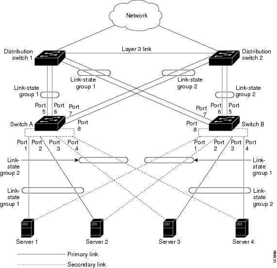
Figure 40-1 shows a network configured with link state tracking. To enable link state tracking, create a link state group, and specify the interfaces that are assigned to the link state group. In a link state group, these interfaces are bundled together. The downstream interfaces are bound to the upstream interfaces. Interfaces connected to servers are referred to as downstream interfaces, and interfaces connected to distribution switches and network devices are referred to as upstream interfaces.
The configuration in Figure 40-1 ensures that the network traffic flow is balanced as follows:
•![]() For links to switches and other network devices
For links to switches and other network devices
–![]() Server 1 and server 2 use switch A for primary links and switch B for secondary links.
Server 1 and server 2 use switch A for primary links and switch B for secondary links.
–![]() Server 3 and server 4 use switch B for primary links and switch A for secondary links.
Server 3 and server 4 use switch B for primary links and switch A for secondary links.
•![]() Link state group 1 on switch A
Link state group 1 on switch A
–![]() Switch A provides primary links to server 1 and server 2 through link state group 1. Port 1 is connected to server 1, and port 2 is connected to server 2. Port 1 and port 2 are the downstream interfaces in link state group 1.
Switch A provides primary links to server 1 and server 2 through link state group 1. Port 1 is connected to server 1, and port 2 is connected to server 2. Port 1 and port 2 are the downstream interfaces in link state group 1.
–![]() Port 5 and port 6 are connected to distribution switch 1 through link state group 1. Port 5 and port 6 are the upstream interfaces in link state group 1.
Port 5 and port 6 are connected to distribution switch 1 through link state group 1. Port 5 and port 6 are the upstream interfaces in link state group 1.
•![]() Link state group 2 on switch A
Link state group 2 on switch A
–![]() Switch A provides secondary links to server 3 and server 4 through link state group 2. Port 3 is connected to server 3, and port 4 is connected to server 4. Port 3 and port 4 are the downstream interfaces in link state group 2.
Switch A provides secondary links to server 3 and server 4 through link state group 2. Port 3 is connected to server 3, and port 4 is connected to server 4. Port 3 and port 4 are the downstream interfaces in link state group 2.
–![]() Port 7 and port 8 are connected to distribution switch 2 through link state group 2. Port 7 and port 8 are the upstream interfaces in link state group 2.
Port 7 and port 8 are connected to distribution switch 2 through link state group 2. Port 7 and port 8 are the upstream interfaces in link state group 2.
•![]() Link state group 2 on switch B
Link state group 2 on switch B
–![]() Switch B provides primary links to server 3 and server 4 through link state group 2. Port 3 is connected to server 3, and port 4 is connected to server 4. Port 3 and port 4 are the downstream interfaces in link state group 2.
Switch B provides primary links to server 3 and server 4 through link state group 2. Port 3 is connected to server 3, and port 4 is connected to server 4. Port 3 and port 4 are the downstream interfaces in link state group 2.
–![]() Port 5 and port 6 are connected to distribution switch 2 through link state group 2. Port 5 and port 6 are the upstream interfaces in link state group 2.
Port 5 and port 6 are connected to distribution switch 2 through link state group 2. Port 5 and port 6 are the upstream interfaces in link state group 2.
•![]() Link state group 1 on switch B
Link state group 1 on switch B
–![]() Switch B provides secondary links to server 1 and server 2 through link state group 1. Port 1 is connected to server 1, and port 2 is connected to server 2. Port 1 and port 2 are the downstream interfaces in link state group 1.
Switch B provides secondary links to server 1 and server 2 through link state group 1. Port 1 is connected to server 1, and port 2 is connected to server 2. Port 1 and port 2 are the downstream interfaces in link state group 1.
–![]() Port 7 and port 8 are connected to distribution switch 1 through link state group 1. Port 7 and port 8 are the upstream interfaces in link state group 1.
Port 7 and port 8 are connected to distribution switch 1 through link state group 1. Port 7 and port 8 are the upstream interfaces in link state group 1.
In a link state group, the upstream ports can become unavailable or lose connectivity because the distribution switch or router fails, the cables are disconnected, or the link is lost. These are the interactions between the downstream and upstream interfaces when link state tracking is enabled:
•![]() If any of the upstream interfaces are in the link-up state, the downstream interfaces can change to or remain in the link-up state.
If any of the upstream interfaces are in the link-up state, the downstream interfaces can change to or remain in the link-up state.
•![]() If all of the upstream interfaces become unavailable, link state tracking automatically puts the downstream interfaces in the error-disabled state. Connectivity to and from the servers is automatically changed from the primary server interface to the secondary server interface.
If all of the upstream interfaces become unavailable, link state tracking automatically puts the downstream interfaces in the error-disabled state. Connectivity to and from the servers is automatically changed from the primary server interface to the secondary server interface.
As an example of a connectivity change from link state group 1 to link state group 2 on switch A, see Figure 40-1. If the upstream link for port 6 is lost, the link states of downstream ports 1 and 2 do not change. However, if the link for upstream port 5 is also lost, the link state of the downstream ports changes to the link-down state. Connectivity to server 1 and server 2 is then changed from link state group1 to link state group 2. The downstream ports 3 and 4 do not change state because they are in link-group 2.
•![]() If the link state group is configured, link state tracking is disabled, and the upstream interfaces lose connectivity, the link states of the downstream interfaces remain unchanged. The server does not recognize that upstream connectivity has been lost and does not failover to the secondary interface.
If the link state group is configured, link state tracking is disabled, and the upstream interfaces lose connectivity, the link states of the downstream interfaces remain unchanged. The server does not recognize that upstream connectivity has been lost and does not failover to the secondary interface.
You can recover a downstream interface link-down condition by removing the failed downstream port from the link state group. To recover multiple downstream interfaces, disable the link state group.
Figure 40-1 Typical Link State Tracking Configuration
Default Link State Tracking Configuration
There are no link state groups defined, and link state tracking is not enabled for any group.
How to Configure Link State Tracking
Configuring Link State Tracking
Monitoring and Maintaining Link State Tracking
|
|
|
|---|---|
show link state group |
Displays the link state group information. |
Configuration Examples for Configuring Link State Tracking
Displaying Link State Information: Examples
Use the show link state group command to display the link state group information. Enter this command without keywords to display information about all link state groups. Enter the group number to display information specific to the group. Enter the detail keyword to display detailed information about the group.
This is an example of output from the show link state group 1 command:
Switch> show link state group 1
Link State Group: 1 Status: Enabled, Down
This is an example of output from the show link state group detail command:
Switch> show link state group detail
(Up):Interface up (Dwn):Interface Down (Dis):Interface disabled
Link State Group: 1 Status: Enabled, Down
Upstream Interfaces : Fa1/7(Dwn) Fa1/8(Dwn)
Downstream Interfaces : Fa1/3(Dis) Fa1/4(Dis) Fa1/5(Dis) Fa1/6(Dis)
Link State Group: 2 Status: Enabled, Down
Upstream Interfaces : Fa1/6(Dwn) Fa1/7(Dwn) Fa1/8(Dwn)
Downstream Interfaces : Fa1/2(Dis) Fa1/3(Dis) Fa1/4(Dis) Fa1/5(Dis)
(Up):Interface up (Dwn):Interface Down (Dis):Interface disabled
Creating a Link State Group: Example
This example shows how to create a link state group and configure the interfaces:
Switch# configure terminal
Switch(config)# link state track 1
Switch(config)# interface range gigabitethernet1/1 -2
Switch(config-if)# link state group 1 upstream
Switch(config-if)# interface gigabitethernet1/1
Switch(config-if)# link state group 1 downstream
Switch(config-if)# interface gigabitethernet1/1
Switch(config-if)# link state group 1 downstream
Switch(config-if)# interface gigabitethernet1/2
Switch(config-if)# link state group 1 downstream
Switch(config-if)# end
Additional References
The following sections provide references related to switch administration:
Related Documents
Standards
|
|
|
|---|---|
No new or modified standards are supported by this feature, and support for existing standards has not been modified by this feature. |
— |
MIBs
|
|
|
|---|---|
— |
To locate and download MIBs using Cisco IOS XR software, use the Cisco MIB Locator found at the following URL and choose a platform under the Cisco Access Products menu: http://cisco.com/public/sw-center/netmgmt/cmtk/mibs.shtml |
RFCs
|
|
|
|---|---|
No new or modified RFCs are supported by this feature, and support for existing RFCs has not been modified by this feature. |
— |
 Feedback