Installing Cisco IOS Software TSN Support on a Cisco IE 4000 Switch
Bias-Free Language
The documentation set for this product strives to use bias-free language. For the purposes of this documentation set, bias-free is defined as language that does not imply discrimination based on age, disability, gender, racial identity, ethnic identity, sexual orientation, socioeconomic status, and intersectionality. Exceptions may be present in the documentation due to language that is hardcoded in the user interfaces of the product software, language used based on RFP documentation, or language that is used by a referenced third-party product. Learn more about how Cisco is using Inclusive Language.
What is time-sensitive networking (TSN)? In its simplest form, TSN is the IEEE 802.1Q defined standard technology to provide
deterministic messaging on standard Ethernet. TSN technology is centrally managed and delivers guarantees of delivery and
minimized jitter using time scheduling for those real-time applications that require determinism.
TSN is a Layer 2 technology. The IEEE 802.1Q standards work at OSI Layer 2. TSN is an Ethernet standard, not an Internet Protocol
standard. The forwarding decisions made by the TSN bridges use the Ethernet header contents, not the IP address. The payloads
of the Ethernet frames can be anything and are not limited to Internet Protocol. This means that TSN can be used in any environment
using standard Ethernet and can carry the payload of any industrial application or protocol.
There’s an implied requirement for those networking devices implementing TSN (end devices and bridges) to share a common sense
of time. Precision Time Protocol (PTP) is used to maintain a common sense of time. The PTP profiles chosen to work with TSN
are IEEE 802.1AS and IEEE 802.1ASRev.
A Shared Concept of Time
The key to providing determinism is a shared concept of time. The implementation of 802.1AS (and in the future 802.1ASRev)
by all network elements (end devices and bridges) is required for TSN. The 802.1AS PTP profile allows all TSN network elements
to share the same concept of time.
802.1Qbv is essential to providing on-time delivery of TSN frames. Qbv defines a means to transmit certain TSN Ethernet frames
on a schedule, while allowing non-TSN Ethernet frames to be transmitted on a best effort basis around the TSN frames. Because
all network elements share the same time, end devices and bridges implementing Qbv can deliver critical communication very
quickly and with no discernible jitter in delivery.
IEEE 802.1Qcc is focused on definition of management interfaces and protocols to enable TSN network administration. 802.1Qcc
is a large specification with many aspects. Cisco is using the centralized approach to network management defined in 802.1Qcc.
TSN System Components
There are five main components in the TSN system:
TSN flow: Term used to describe the time-critical communication between end devices. Each flow has strict time requirements that the
networking devices honor. Each TSN flow is uniquely identified by the network devices.
End Devices:application that requires deterministic communication. These are also referred to as talkers and listeners.
Bridges: Also referred as Ethernet switches. For TSN, these are special bridges capable of transmitting the Ethernet frames of a TSN
flow on a schedule and receiving Ethernet frames of a TSN flow according to a schedule.
Central network controller (CNC): For TSN, the CNC acts as a proxy network (the TSN bridges and their interconnections) to the applications that require deterministic
communication. The CNC defines the schedule on which all TSN frames are transmitted. The CNC application is provided by the
vendor of the TSN bridges. Cisco has developed a CNC application for controlling its TSN bridges for TSN.
Centralized user configuration (CUC): An application that communicates with the CNC and the end devices. The CUC represents the control applications and the end
devices. The CUC makes requests to the CNC for deterministic communication (TSN flows) with specific requirements for those
flows. The CUC is an application that is vendor specific. Typically the vendor of the TSN end devices will supply a CUC for
those end devices.
Overview of Cisco TSN Solution
Cisco is supporting TSN on the IE-4000 product family. All models of IE-4000 support TSN. Starting with Cisco IOS® Software
release 15.2(5)E2, the TSN functionality is available. The IE-4000s have an FPGA in the data path that enable them to support
TSN. The IE-4000 operates as a TSN bridge. The IE-4000 implements IEEE 802.1Qbv and IEEE 802.1AS. The IE-4000 supports hundreds
of TSN flows across its Ethernet interfaces.
As the name suggests, the TSN central network controller (CNC) controls the TSN bridges in the network. The CNC is a software
application running on customer premises (as opposed to cloud). The hardware housing the CNC application is not relevant and
can be anything. The CNC has two primary responsibilities. First, it is responsible for determining routes and scheduling
the TSN flows through the bridged network. Second, it is responsible for configuring the TSN bridges for TSN operation.
The CNC communicates with the CUC to receive the communications requirements that the network must provide. The CNC aggregates
all the requests, figures out the optimal path for each communication request, schedules the end-to-end transmission for each
TSN flow, and finally transfers the computed schedule to each TSN bridge. As part of the schedule computation, the CNC provides
a unique identifier for each TSN flow. This unique identifier is used by the TSN bridges to differentiate one TSN flow from
another. The unique identifier includes the destination MAC address, VLAN ID, and CoS value. With these three items, the TSN
bridges can identify the TSN flow and transmit the flow based on the correct schedule.
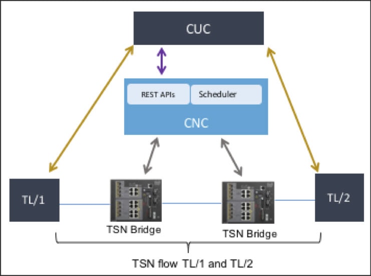
In Figure 1, you can see all the components and how they relate. The CUC communicates with the CNC using REST APIs. The CNC
communicates with both CUC and TSN bridges. The CUC communicates with the talker/listener end devices. The TSN bridges switch
the Ethernet frames of TSN flowss between the talkers and listeners.
Figure 1. Sample Topology for TSN Networking Components
The APIs between the CUC and CNC are defined and available as part of the Cisco TSN documentation. The APIs are there for
everything needed by the CUC to completely program the TSN flows in the network.
Figure 1 shows lines of control plane communication of messages that occur between the CUC and CNC before the talkers and
listeners can start exchanging TSN communications (eg: TSN flows).
The following steps are typical for a workflow and are described only for the purpose of showing how and why the entities
communicate with each other. Disclaimer: This is not the only order in which these steps can be executed.
CUC Initiates Physical Topology Discovery
Before the schedule can be successfully computed, the CNC must learn the physical topology. The engineer (via the CUC) will
initiate a request to the CNC to discover the physical topology. Using LLDP and a seed device, the CNC walks the physical
topology, discovering each device and how they are connected. This includes the end devices that support LLDP.
After completion, the engineer (via the CUC) issues a request of the CNC to return the discovered topology. The engineer at
this point could verify that the CNC discovered the topology correctly if they choose.
CUC Requests Network Resources
Performed by the engineer responsible for defining the end to end communication. The engineer works out which end device (talker)
has to communicate with other end devices (listener). The engineer is responsible for identifying all listeners, because there
can be more than one for each TSN flow. The engineer can also define the latency requirements for the communication (for example,
the listeners must receive within 500µs from start of transmission), the maximum size of the Ethernet packet that will be
sent, and other dependencies (for example, whether there is a sequence order to the TSN flows). The CUC will gather this for
all TSN flow requests and submit to the CNC using an API for accepting requests.
Compute Schedule
Satisfied that the topology has been discovered and the CNC has received all TSN flow requests, the engineer (via the CUC)
will initiate a request that the CNC compute the schedule. The CNC will return success or failure for the request. The end
schedule cannot be computed unless the CNC knows the physical topology. Step 3 depends on steps 1 and 2.
View Computation Results
Typically the network engineer would want to view the schedule and verify before making it go live. The engineer (via the
CUC) requests the CNC return the details of the computed schedule. This includes the details for each device involved in the
TSN flows. The details include everything the end devices and bridges need to know for configuring TSN:
Unique identifiers for each TSN flow (destination MAC address, VLAN, CoS)
Start and end of transmit window at each hop (talkers and bridges)
Start and end of receive window at each hop (listeners and bridges)
End-to-end latency as computed
Note
Steps 1 through 4 can be repeated as often as desired.
Distribute Schedule
Satisfied that the schedule will work, the engineer (via the CUC) issues a request to the CNC to distribute the computed schedule
to the TSN bridges. The CUC will also program the talkers and listeners for the TSN flows. The talkers are expected to transmit
every TSN flow according to a schedule.
Verify Schedule Distribution on TSN Bridges
This step is optional. In troubleshooting scenarios, users can log in to the TSN bridges to verify the schedule for the TSN
flows.
CNC to TSN Bridge Control Plane
The CNC and TSN Bridge communicate on two occasions. When the CNC discovers the physical network, and when the CNC distributes
the computed schedules. The CNC and TSN bridges are connected with a Layer 3 IP connection. They do not have to be in the
same subnet, even though that often happens.
Network Discovery
Before the CNC can distribute, it must do a discovery. The CNC must know where to distribute, and how to compute schedules.
Can’t compute schedules accurately until the CNC knows exactly how all the Talkers and Listeners are connected. The CNC discovers
the network doing a crawl of the LLDP tables on the TSN Bridges.
The CNC requires a ‘seed’ device to start the discovery. to start with the ‘seed’ the administrator must provide a device
Hostname for Bridge and an IP Address. From there it will visit all TSN bridges and end devices it can find. For network discovery
to be successful, each TSN Bridge must have a unique host name. This means the administrator must change the hostname from
‘Switch’ to something unique within the network. The end devices should have unique names too.
Use the IOS CLI command ‘show lldp neighbor detail’ on the TSN Bridge to view neighbors and their details. The output of this
command is the same info the CNC uses.
The CNC will log into the TSN Bridges using Telnet. For this to succeed, the login password needs to be configured and the
CNC must know what it is. It needs to be the same for all TSN Bridges. By default the CNC uses ‘admin’ as the login password.
Unless the login password is changed on the CNC, the TSN Bridges must have ‘admin’ configured as well.
Schedule Distribution
After CNC has successfully computed a schedule, the schedule is not active until it is distributed to the TSN Bridges. The
CNC and TSN Bridges have a layer 3 connection to allow the TSN Bridges to receive the schedule. Each TSN bridge has its own
connection to the CNC and each Bridge receives its own schedule. On each TSN Bridge, the IP address of the CNC must be configured.
Every time the CNC successfully computes a schedule, it generates an ID for that schedule. The ID is a 4 byte hex value that
is unique for each schedule. When the distribution is successful, the TSN Brigde will show the schedule ID that is in operation.
It should match the schedule ID on the CNC.
For schedule distribution to work, the TSN Bridge must know how to contact the CNC to get the schedule. This requires a 1
line configuration command on the TSN Bridge: TSN_Bridge (config)# tsn cnc-server <IP Address of CNC>
To confirm the CNC is communicating with the TSN Bridge use commands ‘show tsn cnc’, and ‘show tsn schedule’.
TSN_Bridge # show tsn schedule
Device   ID: TSN_Bridge
Schedule ID: 1492128178 - 0x58F011B2
Status     : TSN schedule has been programmed successfully

TSN_Bridge # show tsn cnc
CNC Connection Status
----------------------------------------------------------------------
Device name:               TSN_Bridge
CNC server:                2.1.28.16:4569
Last CNC Contact:          17:22:50  Fri May 5 2017
Last Good CNC Connection:  17:22:52  Fri May 5 2017
Current Schedule ID:       1492128178 - 0x58F011B2
The data plane on the IE4000 is concerned only with the ingress and egress of TSN flows. Once the CNC distributes schedules
to the Bridges, and the Talker and Listeners end devices have also been given their TSN flows schedules, the focus shifts
to the Networking devices and not the CNC.
The CNC is in the control plane only. If the CNC is powered off or disconnected, it will not impact the operation of the TSN
flows.
Each TSN flow is traffic engineered through the bridged Ethernet network. The CNC determined the forwarding path as part of
the computation of the schedule. The TSN bridges forward TSN flows according to how the CNC instructed. TSN bridges do not
use dynamic learning of MAC address for TSN flows.
The Vlan(s) used for TSN flows do not run Spanning Tree. Its mandatory that spanning tree be disabled on all vlans containing
TSN flows. If the TSN Bridge receives an Ethernet packet that does not belong to an expected TSN flow on that interface for
that vlan, the bridge will drop the packet. TSN vlans should not have Broadcast packets. All TSN flows have vlan tags in the
Ethernet header. All interfaces on the TSN bridges that are expected to receive or transmit TSN flows must be in trunk mode.
On the IE4000, interfaces expecting TSN flows are automatically placed into trunk mode. the TSN vlan(s) cannot be the ‘access’
vlan on the Ethernet interfaces.
The Cisco TSN Bridges use service policies on ingress and egress to ensure the TSN flows receive proper quality of service
within the internal switching infrastructure. The TSN flows use the high priority Queue to prevent them from being delayed
during egress congestion. For all interfaces that support a TSN flow, an ingress and an egress service policy will be automatically
applied to the interface for QOS purposes.
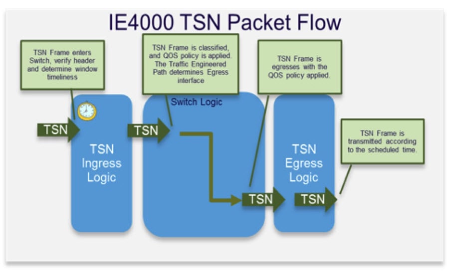
The figure below shows the HW architecture for the Cisco TSN Bridge. This will aid in troubleshooting and monitoring TSN flows.
To view the TSN flows that have scheduled for a TSN Bridge, there are two CLI commands for summary and detailed view.
TSN_Volt1# show tsn flow summary
Flow-ID Stream-ID               DMAC           Status Ingress  Egress
------- ----------------------- -------------- ------ -------- ----------
1001    flow1                   0300.5EA0.03E9 up     Gi1/5    Gi1/4
1002    flow2                   0300.5EA0.03EA up     Gi1/4    Gi1/5

TSN_Bridge# show tsn flow details
Flow 1001
    Stream ID : flow1
    Stream Address : 0300.5EA0.03E9
    Frame Size : 64B
    Ingress Interface : Rx Schedule
     Gi1/5: 13-26 (us)
    Egress Interface : TX Schedule
     Gi1/4: 207-220 (us)
    Period cycle time : 1000 (us)
Flow 1002
    Stream ID : flow2
    Stream Address : 0300.5EA0.03EA
    Frame Size : 64B
    Ingress Interface : Rx Schedule
     Gi1/4: 245-258 (us)
    Egress Interface : TX Schedule
     Gi1/5: 283-295 (us)
    Period cycle time : 1000 (us)
Ingress of TSN Flows
All flows that ingress the TSN bridge have an expected window of time when they are expected. This window is approximately
13us for 1000Mbps links and 130us for 100Mbps links. TSN is not supported on 10Mbps links. The Cisco TSN bridge is able to
determine if a given flow is ingressing on time (eg: in the scheduled window). For each TSN flow, a count is maintained for
ingressing early, on time, or late. This is useful in case there are any issues with the end to end TSN flow, and it needs
to be root caused. For TSN flows not ingressing on time, one possible reason is the transmitter not being in clock synchronization
with the network.
Use command “show interface <interface id> tsn ingress stats <flow id>” to see ingress statistics for each tsn flow. The interface and the tsn flow id are required.
Example:
TSN_Switch # show interface Gig1/4 tsn ingress stats 1002
                   Latest         Accumulated
                   ------         ------------
Unexpected         0              0
In                 254476         267372
Early              0              0
Late               0              9003
‘In’ counts packets in the flow received within the expected window. The ‘Latest’ column clears on read and shows counts since
the last read. ‘Accumulated’ column maintains history and doesn’t clear unless an explicit action to clear counters is made.
Egress of TSN Flows
Similar to ingress, all TSN flows that egress have an expected window of time when they are expected to egress the TSN Bridge.
It doesn’t matter if this interface is bridge to bridge or bridge to the Listener end device, the Cisco TSN Bridge will not
transmit the frames of a TSN flow until it is time do to so. This means the TSN bridge has to hold on and delay the TSN frame.
The egress window can be seen using ‘show tsn flow details’ CLI command.
The easiest way to confirm that a TSN flow is working correctly on egress is to look at egress counts for each flow. Use this
command to see egress counts per flow:show interface <intf id> tsn flow-stats <flow id>.

 Feedback