The documentation set for this product strives to use bias-free language. For the purposes of this documentation set, bias-free is defined as language that does not imply discrimination based on age, disability, gender, racial identity, ethnic identity, sexual orientation, socioeconomic status, and intersectionality. Exceptions may be present in the documentation due to language that is hardcoded in the user interfaces of the product software, language used based on RFP documentation, or language that is used by a referenced third-party product. Learn more about how Cisco is using Inclusive Language.
Before you begin the PIM configuration process, decide which PIM mode to use. This is based on the applications you intend
to support on your network. Use the following guidelines:
In general, if the application is one-to-many or many-to-many in nature, then PIM-SM can be used successfully.
For optimal one-to-many application performance, SSM is appropriate but requires IGMP version 3 support.
Before you configure PIM stub routing, check that you have met these conditions:
You must have IP multicast routing configured on both the stub router and the central router. You must also have PIM mode
configured on the uplink interface of the stub router.
You must also configure either Enhanced Interior Gateway Routing Protocol (EIGRP) stub routing or Open Shortest Path First
(OSPF) stub routing on the device.
The PIM stub router does not route the transit traffic between the distribution routers. Unicast (EIGRP) stub routing enforces
this behavior. You must configure unicast stub routing to assist the PIM stub router behavior.
Restrictions for PIM
The following are the restrictions for configuring PIM:
Use ACLs to designate a specified port only as a multicast host port and not as a multicast router port. Multicast router
control-packets received on this port are dropped.
PIM nonbroadcast multiaccess (NBMA) mode is not supported on an ethernet interface.
Hot Standby Router Protocol-aware (HSRP-aware) PIM is not supported.
PIMv1 and PIMv2 Interoperability
To avoid misconfiguring multicast routing on your device, review the information in this section.
The Cisco PIMv2 implementation provides interoperability and transition between Version 1 and Version 2, although there might
be some minor problems.
You can upgrade to PIMv2 incrementally. PIM Versions 1 and 2 can be configured on different routers and multilayer switches
within one network. Internally, all routers and multilayer switches on a shared media network must run the same PIM version.
Therefore, if a PIMv2 device detects a PIMv1 device, the Version 2 device downgrades itself to Version 1 until all Version
1 devices have been shut down or upgraded.
PIMv2 uses the BSR to discover and announce RP-set information for each group prefix to all the routers and multilayer switches
in a PIM domain. PIMv1, together with the Auto-RP feature, can perform the same tasks as the PIMv2 BSR. However, Auto-RP is
a standalone protocol, separate from PIMv1, and is a proprietary Cisco protocol. PIMv2 is a standards track protocol in the
IETF.
Note
We recommend that you use PIMv2. The BSR function interoperates with Auto-RP on Cisco routers and multilayer switches.
When PIMv2 devices interoperate with PIMv1 devices, Auto-RP should have already been deployed. A PIMv2 BSR that is also an
Auto-RP mapping agent automatically advertises the RP elected by Auto-RP. That is, Auto-RP sets its single RP on every router
or multilayer switch in the group. Not all routers and switches in the domain use the PIMv2 hash function to select multiple
RPs.
Sparse-mode groups in a mixed PIMv1 and PIMv2 region are possible because the Auto-RP feature in PIMv1 interoperates with
the PIMv2 RP feature. Although all PIMv2 devices can also use PIMv1, we recommend that the RPs be upgraded to PIMv2. To ease
the transition to PIMv2, we recommend:
Using Auto-RP throughout the region.
If Auto-RP is not already configured in the PIMv1 regions, configure Auto-RP.
Restrictions for Bidirectional PIM
Phantom rendezvous point (RP) is not supported.
Restrictions for Configuring PIM Stub Routing
Only directly connected multicast (IGMP) receivers and sources are allowed in the Layer 2 access domains. The PIM protocol
is not supported in access domains.
In a network using PIM stub routing, the only allowable route for IP traffic to the user is through a device that is configured
with PIM stub routing.
The redundant PIM stub router topology is not supported. Only the nonredundant access router topology is supported by the
PIM stub feature.
Restrictions for Configuring Auto-RP and BSR
Take into consideration your network configuration, and the following restrictions when configuring Auto-RP and BSR:
Restrictions for Configuring Auto-RP
The following are restrictions for configuring Auto-RP (if used in your network configuration):
If routed interfaces are configured in sparse mode, Auto-RP can still be used if all devices are configured with a manual
RP address for the Auto-RP groups.
If routed interfaces are configured in sparse mode and you enter the ip pim autorp listener global configuration command, Auto-RP can still be used even if all devices are not configured with a manual RP address for
the Auto-RP groups.
Restrictions for Configuring BSR
The following are the restrictions for configuring BSR (if used in your network configuration):
Configure the candidate BSRs as the RP-mapping agents for Auto-RP.
For group prefixes advertised through Auto-RP, the PIMv2 BSR mechanism should not advertise a subrange of these group prefixes
served by a different set of RPs. In a mixed PIMv1 and PIMv2 domain, have backup RPs serve the same group prefixes. This prevents
the PIMv2 DRs from selecting a different RP from those PIMv1 DRs, due to the longest match lookup in the RP-mapping database.
Restrictions and Guidelines for Configuring Auto-RP and BSR
The following are restrictions for configuring Auto-RP and BSR (if used in your network configuration):
If your network is all Cisco routers and multilayer switches, you can use either Auto-RP or BSR.
If you have non-Cisco routers in your network, you must use BSR.
If you have Cisco PIMv1 and PIMv2 routers and multilayer switches and non-Cisco routers, you must use both Auto-RP and BSR.
If your network includes routers from other vendors, configure the Auto-RP mapping agent and the BSR on a Cisco PIMv2 device.
Ensure that no PIMv1 device is located in the path a between the BSR and a non-Cisco PIMv2 device.
Note
There are two approaches to using PIMv2. You can use Version 2 exclusively in your network or migrate to Version 2 by employing
a mixed PIM version environment.
Because bootstrap messages are sent hop-by-hop, a PIMv1 device prevents these messages from reaching all routers and multilayer
switches in your network. Therefore, if your network has a PIMv1 device in it and only Cisco routers and multilayer switches,
it is best to use Auto-RP.
If you have a network that includes non-Cisco routers, configure the Auto-RP mapping agent and the BSR on a Cisco PIMv2 router
or multilayer switch. Ensure that no PIMv1 device is on the path between the BSR and a non-Cisco PIMv2 router.
If you have non-Cisco PIMv2 routers that need to interoperate with Cisco PIMv1 routers and multilayer switches, both Auto-RP
and a BSR are required. We recommend that a Cisco PIMv2 device be both the Auto-RP mapping agent and the BSR.
Restrictions for Auto-RP Enhancement
The simultaneous deployment of Auto-RP and bootstrap router (BSR) is not supported.
Information about PIM
Protocol Independent Multicast Overview
The Protocol Independent Multicast (PIM) protocol maintains the current IP multicast service mode of receiver-initiated membership.
PIM is not dependent on a specific unicast routing protocol; it is IP routing protocol independent and can leverage whichever
unicast routing protocols are used to populate the unicast routing table, including Enhanced Interior Gateway Routing Protocol
(EIGRP), Open Shortest Path First (OSPF), Border Gateway Protocol (BGP), and static routes. PIM uses unicast routing information to perform the multicast forwarding function.
Although PIM is called a multicast routing protocol, it actually uses the unicast routing table to perform the reverse path
forwarding (RPF) check function instead of building up a completely independent multicast routing table. Unlike other routing
protocols, PIM does not send and receive routing updates between routers.
PIM is defined in RFC 4601, Protocol Independent Multicast - Sparse Mode (PIM-SM)
PIM Versions
PIMv2 includes these improvements over PIMv1:
A single, active rendezvous point (RP) exists per multicast group, with multiple backup RPs. This single RP compares to multiple
active RPs for the same group in PIMv1.
A bootstrap router (BSR) provides a fault-tolerant, automated RP discovery and distribution function that enables routers
and multilayer switches to dynamically learn the group-to-RP mappings.
PIM join and prune messages have more flexible encoding for multiple address families.
A more flexible hello packet format replaces the query packet to encode current and future capability options.
Register messages sent to an RP specify whether they are sent by a border router or a designated router.
PIM packets are no longer inside IGMP packets; they are standalone packets.
Multicast Source Discovery Protocol (MSDP)
Multicast Source Discovery Protocol (MSDP) is used for inter-domain source discovery when PIM SM is used. Each PIM administrative
domain has its own RP. In order for the RP in one domain to signal new sources to the RP in the other domain, MSDP is used.
When RP in a domain receives a PIM register message for a new source, with MSDP configured it sends a new source-active (SA)
message to all its MSDP peers in other domains. Each intermediate MSDP peer floods this SA message away from the originating
RP. The MSDP peers install this SA message in their MSDP sa-cache. If the RPs in other domains have any join requests for
the group in the SA message (indicated by the presence of a (*,G) entry with non empty outgoing interface list), the domain
is interested in the group, and the RP triggers an (S,G) join toward the source.
PIM Sparse Mode
PIM sparse mode (PIM-SM) uses a pull model to deliver multicast traffic. Only network segments with active receivers that
have explicitly requested the data will receive the traffic.
Sparse mode interfaces are added to the multicast routing table only when periodic Join messages are received from downstream
routers, or when a directly connected member is on the interface. When forwarding from a LAN, sparse mode operation occurs
if an RP is known for the group. If so, the packets are encapsulated and sent toward the RP. If the multicast traffic from
a specific source is sufficient, the first hop router of the receiver may send Join messages toward the source to build a
source-based distribution tree.
PIM-SM distributes information about active sources by forwarding data packets on the shared tree. Because PIM-SM uses shared
trees (at least, initially), it requires the use of a rendezvous point (RP). The RP must be administratively configured in
the network. See the Rendezvous Points section for more information.
In sparse mode, a router assumes that other routers do not want to forward multicast packets for a group, unless there is
an explicit request for the traffic. When hosts join a multicast group, the directly connected routers send PIM Join messages
toward the RP. The RP keeps track of multicast groups. Hosts that send multicast packets are registered with the RP by the
first hop router of that host. The RP then sends Join messages toward the source. At this point, packets are forwarded on
a shared distribution tree. If the multicast traffic from a specific source is sufficient, the first hop router of the host
may send Join messages toward the source to build a source-based distribution tree.
Sources register with the RP and then data is forwarded down the shared tree to the receivers. The edge routers learn about
a particular source when they receive data packets on the shared tree from that source through the RP. The edge router then
sends PIM (S,G) Join messages toward that source. Each router along the reverse path compares the unicast routing metric of
the RP address to the metric of the source address. If the metric for the source address is better, it will forward a PIM
(S,G) Join message toward the source. If the metric for the RP is the same or better, then the PIM (S,G) Join message will
be sent in the same direction as the RP. In this case, the shared tree and the source tree would be considered congruent.
If the shared tree is not an optimal path between the source and the receiver, the routers dynamically create a source tree
and stop traffic from flowing down the shared tree. This behavior is the default behavior in software. Network administrators
can force traffic to stay on the shared tree by using the ippimspt-thresholdinfinity command.
PIM-SM scales well to a network of any size, including those with WAN links. The explicit join mechanism prevents unwanted
traffic from flooding the WAN links.
Bidirectional PIM
Bidirectional PIM is a variant of the PIM suite of routing protocols for IP multicast. In PIM, packet traffic for a multicast
group is routed according to the rules of the mode configured for that multicast group.
In bidirectional mode, traffic is routed only along a bidirectional shared tree that is rooted at the rendezvous point (RP)
for the group. In bidir-PIM, the IP address of the RP acts as the key to having all routers establish a loop-free spanning
tree topology rooted in that IP address. This IP address need not be a router, but can be any unassigned IP address on a network
that is reachable throughout the PIM domain. This technique is the preferred configuration method for establishing a redundant
RP configuration for bidir-PIM.
Membership to a bidirectional group is signalled via explicit join messages. Traffic from sources is unconditionally sent
up the shared tree toward the RP and passed down the tree toward the receivers on each branch of the tree.
Bidir-PIM is designed to be used for many-to-many applications within individual PIM domains. Multicast groups in bidirectional
mode can scale to an arbitrary number of sources without incurring overhead due to the number of sources.
PIM-SM cannot forward traffic in the upstream direction of a tree, because it only accepts traffic from one Reverse Path Forwarding
(RPF) interface. This interface (for the shared tree) points toward the RP, therefore allowing only downstream traffic flow.
In this case, upstream traffic is first encapsulated into unicast register messages, which are passed from the designated
router (DR) of the source toward the RP. In a second step, the RP joins an SPT that is rooted at the source. Therefore, in
PIM-SM, traffic from sources traveling toward the RP does not flow upstream in the shared tree, but downstream along the SPT
of the source until it reaches the RP. From the RP, traffic flows along the shared tree toward all receivers.
Bidir-PIM is derived from the mechanisms of PIM-SM and shares many shortest-path tree (SPT) operations. Bidir-PIM also has
unconditional forwarding of source traffic toward the RP upstream on the shared tree, but no registering process for sources
as in PIM-SM. These modifications are necessary and sufficient to allow forwarding of traffic in all routers solely based
on the (*, G) multicast routing entries. This feature eliminates any source-specific state and allows scaling capability to
an arbitrary number of sources. The following figures show the difference in state created per router for a unidirectional
shared tree and source tree versus a bidirectional shared tree.
Figure 1. Unidirectional Shared Tree and Source Tree
Figure 2. Bidirectional Shared Tree
When packets are forwarded downstream from the RP toward receivers, there are no fundamental differences between bidir-PIM
and PIM-SM. Bidir-PIM deviates substantially from PIM-SM when passing traffic from sources upstream toward the RP.
In bidir-PIM, the packet forwarding rules have been improved over PIM-SM, allowing traffic to be passed up the shared tree
toward the RP. To avoid multicast packet looping, bidir-PIM introduces a new mechanism called designated forwarder (DF) election,
which establishes a loop-free SPT rooted at the RP.
Designated Forwarder Election
On every network segment and point-to-point link, all PIM routers participate in a procedure called Designated Forwarder (DF)
election. The procedure selects one router as the DF for every RP of bidirectional groups. This router is responsible for
forwarding multicast packets received on that network upstream to the RP.
The DF election is based on unicast routing metrics and uses the same tie-break rules employed by PIM assert processes. The
router with the most preferred unicast routing metric to the RP becomes the DF. Use of this method ensures that only one copy
of every packet will be sent to the RP, even if there are parallel equal cost paths to the RP.
A DF is selected for every RP of bidirectional groups. As a result, multiple routers may be elected as DF on any network segment,
one for each RP. In addition, any particular router may be elected as DF on more than one interface.
Bidirectional Group Tree Building
The procedure for joining the shared tree of a bidirectional group is almost identical to that used in PIM SM. One main difference
is that, for bidirectional groups, the role of the DR is assumed by the DF for the RP.
On a network with local receivers, only the router elected as the DF populates the outgoing interface list (olist) upon receiving
Internet Group Management Protocol (IGMP) join messages, and sends (*, G) join and leave messages upstream toward the RP.
When a downstream router wishes to join the shared tree, the RPF neighbor in the PIM join and leave messages is always the
DF elected for the interface leading to the RP.
When a router receives a join or leave message, and the router is not the DF for the receiving interface, the message is ignored.
Otherwise, the router updates the shared tree in the same way as in sparse mode.
In a network where all routers support bidirectional shared trees, (S, G) join and leave messages are ignored. There is also
no need to send PIM assert messages, because the DF election procedure eliminates parallel downstream paths from any RP. In
addition, an RP never joins a path back to the source, nor will it send any register stops.
Packet Forwarding
A router only creates (*, G) entries for bidirectional groups. The olist of a (*, G) entry includes all the interfaces for
which the router has been elected DF and that have received either an IGMP or PIM join message. If a router is located on
a sender-only branch, it will also create (*, G) state, but the olist will not include any interfaces.
If a packet is received from the RPF interface toward the RP, the packet is forwarded downstream according to the olist of
the (*, G) entry. Otherwise, only the router that is the DF for the receiving interface forwards the packet upstream toward
the RP; all other routers must discard the packet.
IPv4 Bidirectional PIM
For Bidirectional PIM to be operational, designated forwarder is required. The designated forwarder is the router elected
to forward packets to and from a segment for a IPv4 bidirectional PIM group. In DF mode, the switch accepts packets from the
RPF and from the DF interfaces.
When the switch is forwarding IPv4 bidirectional PIM groups, the RPF interface is always included in the outgoing interface
list of (*,G) entry, and the DF interfaces are included depending on IGMP/PIM joins.
If the route to the RP becomes unavailable, the group is changed to dense mode. Should the RPF link to the RP become unavailable,
the IPv4 bidirectional PIM flow is removed from the hardware FIB.
PIM Stub Routing
The PIM stub routing feature, available in all of the device software images, reduces resource usage by moving routed traffic
closer to the end user.
The PIM stub routing feature supports multicast routing between the distribution layer and the access layer. It supports two
types of PIM interfaces, uplink PIM interfaces, and PIM passive interfaces. A routed interface configured with the PIM passive
mode does not pass or forward PIM control traffic, it only passes and forwards IGMP traffic.
In a network using PIM stub routing, the only allowable route for IP traffic to the user is through a device that is configured
with PIM stub routing. PIM passive interfaces are connected to Layer 2 access domains, such as VLANs, or to interfaces that
are connected to other Layer 2 devices. Only directly connected multicast (IGMP) receivers and sources are allowed in the
Layer 2 access domains. The PIM passive interfaces do not send or process any received PIM control packets.
When using PIM stub routing, you should configure the distribution and remote routers to use IP multicast routing and configure
only the device as a PIM stub router. The device does not route transit traffic between distribution routers. You also need
to configure a routed uplink port on the device. The device uplink port cannot be used with SVIs. If you need PIM for an SVI
uplink port, you should upgrade to the Network Advantage license.
Note
You must also configure EIGRP stub routing when configuring PIM stub routing on the device
The redundant PIM stub router topology is not supported. The redundant topology exists when there is more than one PIM router
forwarding multicast traffic to a single access domain. PIM messages are blocked, and the PIM asset and designated router
election mechanisms are not supported on the PIM passive interfaces. Only the nonredundant access router topology is supported
by the PIM stub feature. By using a nonredundant topology, the PIM passive interface assumes that it is the only interface
and designated router on that access domain.
Figure 3. PIM Stub Router Configuration. In the following figure, the Device A routed uplink port 25 is connected to the router and PIM stub routing is enabled on
the VLAN 100 interfaces and on Host 3. This configuration allows the directly connected hosts to receive traffic from multicast
source 200.1.1.3.
Rendezvous Points
A rendezvous point (RP) is a role that a device performs when operating in Protocol Independent Multicast (PIM) Sparse Mode
(SM). An RP is required only in networks running PIM SM. In the PIM-SM model, only network segments with active receivers
that have explicitly requested multicast data will be forwarded the traffic.
An RP acts as the meeting place for sources and receivers of multicast data. In a PIM-SM network, sources must send their
traffic to the RP. This traffic is then forwarded to receivers down a shared distribution tree. By default, when the first
hop device of the receiver learns about the source, it will send a Join message directly to the source, creating a source-based
distribution tree from the source to the receiver. This source tree does not include the RP unless the RP is located within
the shortest path between the source and receiver.
In most cases, the placement of the RP in the network is not a complex decision. By default, the RP is needed only to start
new sessions with sources and receivers. Consequently, the RP experiences little overhead from traffic flow or processing.
In PIM version 2, the RP performs less processing than in PIM version 1 because sources must only periodically register with
the RP to create state.
Auto-RP
In the first version of PIM-SM, all leaf routers (routers directly connected to sources or receivers) were required to be
manually configured with the IP address of the RP. This type of configuration is also known as static RP configuration. Configuring
static RPs is relatively easy in a small network, but it can be laborious in a large, complex network.
Following the introduction of PIM-SM version 1, Cisco implemented a version of PIM-SM with the Auto-RP feature. Auto-RP automates
the distribution of group-to-RP mappings in a PIM network. Auto-RP has the following benefits:
Configuring the use of multiple RPs within a network to serve different groups is easy.
Auto-RP allows load splitting among different RPs and arrangement of RPs according to the location of group participants.
Auto-RP avoids inconsistent, manual RP configurations that can cause connectivity problems.
Multiple RPs can be used to serve different group ranges or serve as backups to each other. For Auto-RP to work, a router
must be designated as an RP-mapping agent, which receives the RP-announcement messages from the RPs and arbitrates conflicts.
The RP-mapping agent then sends the consistent group-to-RP mappings to all other routers. Thus, all routers automatically
discover which RP to use for the groups they support.
Note
If router interfaces are configured in sparse mode, Auto-RP can still be used if all routers are configured with a static
RP address for the Auto-RP groups.
To make Auto-RP work, a router must be designated as an RP mapping agent, which receives the RP announcement messages from
the RPs and arbitrates conflicts. Thus, all routers automatically discover which RP to use for the groups they support. The
Internet Assigned Numbers Authority (IANA) has assigned two group addresses, 224.0.1.39 and 224.0.1.40, for Auto-RP. One advantage
of Auto-RP is that any change to the RP designation must be configured only on the routers that are RPs and not on the leaf
routers. Another advantage of Auto-RP is that it offers the ability to scope the RP address within a domain. Scoping can be
achieved by defining the time-to-live (TTL) value allowed for the Auto-RP advertisements.
Each method for configuring an RP has its own strengths, weaknesses, and level of complexity. In conventional IP multicast
network scenarios, we recommend using Auto-RP to configure RPs because it is easy to configure, well-tested, and stable. The
alternative ways to configure an RP are static RP, Auto-RP, and bootstrap router.
The Role of Auto-RP in a PIM Network
Auto-RP automates the distribution of group-to-rendezvous point (RP) mappings in a PIM network. To make Auto-RP work, a device
must be designated as an RP mapping agent, which receives the RP announcement messages from the RPs and arbitrates conflicts.
Thus, all routers automatically discover which RP to use for the groups they support. The Internet Assigned Numbers Authority
(IANA) has assigned two group addresses, 224.0.1.39 and 224.0.1.40, for Auto-RP.
The mapping agent receives announcements of intention to become the RP from Candidate-RPs. The mapping agent then announces
the winner of the RP election. This announcement is made independently of the decisions by the other mapping agents.
Multicast Boundaries
Administratively-scoped boundaries can be used to limit the forwarding of multicast traffic outside of a domain or subdomain.
This approach uses a special range of multicast addresses, called administratively-scoped addresses, as the boundary mechanism.
If you configure an administratively-scoped boundary on a routed interface, multicast traffic whose multicast group addresses
fall in this range cannot enter or exit this interface, which provides a firewall for multicast traffic in this address range.
Note
Multicast boundaries and TTL thresholds control the scoping of multicast domains; however, TTL thresholds are not supported
by the device. You should use multicast boundaries instead of TTL thresholds to limit the forwarding of multicast traffic
outside of a domain or a subdomain.
Figure 4. Administratively-Scoped Boundaries. The following figure shows that Company XYZ has an administratively-scoped boundary set for the multicast address range 239.0.0.0/8
on all routed interfaces at the perimeter of its network. This boundary prevents any multicast traffic in the range 239.0.0.0
through 239.255.255.255 from entering or leaving the network. Similarly, the engineering and marketing departments have an
administratively-scoped boundary of 239.128.0.0/16 around the perimeter of their networks. This boundary prevents multicast
traffic in the range of 239.128.0.0 through 239.128.255.255 from entering or leaving their respective networks.
You can define an administratively-scoped boundary on a routed interface for multicast group addresses. A standard access
list defines the range of addresses affected. When a boundary is defined, no multicast data packets are allowed to flow across
the boundary from either direction. The boundary allows the same multicast group address to be reused in different administrative
domains.
The IANA has designated the multicast address range 239.0.0.0 to 239.255.255.255 as the administratively-scoped addresses.
This range of addresses can then be reused in domains administered by different organizations. The addresses would be considered
local, not globally unique.
You can configure the filter-autorp keyword to examine and filter Auto-RP discovery and announcement messages at the administratively scoped boundary. Any Auto-RP
group range announcements from the Auto-RP packets that are denied by the boundary access control list (ACL) are removed.
An Auto-RP group range announcement is permitted and passed by the boundary only if all addresses in the Auto-RP group range
are permitted by the boundary ACL. If any address is not permitted, the entire group range is filtered and removed from the
Auto-RP message before the Auto-RP message is forwarded.
Sparse-Dense Mode for Auto-RP
A prerequisite of Auto-RP is that all interfaces must be configured in sparse-dense mode using the ippimsparse-dense-mode interface configuration command. An interface configured in sparse-dense mode is treated in either sparse mode or dense mode
of operation, depending on which mode the multicast group operates. If a multicast group has a known RP, the interface is
treated in sparse mode. If a group has no known RP, by default the interface is treated in dense mode and data will be flooded
over this interface. (You can prevent dense-mode fallback; see the module “Configuring Basic IP Multicast.”)
To successfully implement Auto-RP and prevent any groups other than 224.0.1.39 and 224.0.1.40 from operating in dense mode,
we recommend configuring a “sink RP” (also known as “RP of last resort”). A sink RP is a statically configured RP that may
or may not actually exist in the network. Configuring a sink RP does not interfere with Auto-RP operation because, by default,
Auto-RP messages supersede static RP configurations. We recommend configuring a sink RP for all possible multicast groups
in your network, because it is possible for an unknown or unexpected source to become active. If no RP is configured to limit
source registration, the group may revert to dense mode operation and be flooded with data.
Auto RP Benefits
Benefits of Auto-RP in a PIM Network
Auto-RP allows any change to the RP designation to be configured only on the devices that are RPs, not on the leaf routers.
Auto-RP offers the ability to scope the RP address within a domain.
PIM Domain Border
As IP multicast becomes more widespread, the chance of one PIMv2 domain bordering another PIMv2 domain increases. Because
two domains probably do not share the same set of RPs, BSR, candidate RPs, and candidate BSRs, you need to constrain PIMv2
BSR messages from flowing into or out of the domain. Allowing messages to leak across the domain borders could adversely affect
the normal BSR election mechanism and elect a single BSR across all bordering domains and comingle candidate RP advertisements,
resulting in the election of RPs in the wrong domain.
This figure displays how you can configure the PIM domain border by using the ip pim bsr-border command.
PIMv2 Bootstrap Router
PIMv2 Bootstrap Router (BSR) is another method to distribute group-to-RP mapping information to all PIM routers and multilayer
devices in the network. It eliminates the need to manually configure RP information in every router and switch in the network.
However, instead of using IP multicast to distribute group-to-RP mapping information, BSR uses hop-by-hop flooding of special
BSR messages to distribute the mapping information.
The BSR is elected from a set of candidate routers and switches in the domain that have been configured to function as BSRs.
The election mechanism is similar to the root-bridge election mechanism used in bridged LANs. The BSR election is based on
the BSR priority of the device contained in the BSR messages that are sent hop-by-hop through the network. Each BSR device
examines the message and forwards out all interfaces only the message that has either a higher BSR priority than its BSR priority
or the same BSR priority, but with a higher BSR IP address. Using this method, the BSR is elected.
The elected BSR sends BSR messages with a TTL of 1. Neighboring PIMv2 routers or multilayer devices receive the BSR message
and multicast it out all other interfaces (except the one on which it was received) with a TTL of 1. In this way, BSR messages
travel hop-by-hop throughout the PIM domain. Because BSR messages contain the IP address of the current BSR, the flooding
mechanism enables candidate RPs to automatically learn which device is the elected BSR.
Candidate RPs send candidate RP advertisements showing the group range for which they are responsible to the BSR, which stores
this information in its local candidate-RP cache. The BSR periodically advertises the contents of this cache in BSR messages
to all other PIM devices in the domain. These messages travel hop-by-hop through the network to all routers and switches,
which store the RP information in the BSR message in their local RP cache. The routers and switches select the same RP for
a given group because they all use a common RP hashing algorithm.
Multicast Forwarding
Forwarding of multicast traffic is accomplished by multicast-capable routers. These routers create distribution trees that
control the path that IP multicast traffic takes through the network in order to deliver traffic to all receivers.
Multicast traffic flows from the source to the multicast group over a distribution tree that connects all of the sources
to all of the receivers in the group. This tree may be shared by all sources (a shared tree) or a separate distribution tree
can be built for each source (a source tree). The shared tree may be one-way or bidirectional.
Before describing the structure of source and shared trees, it is helpful to explain the notations that are used in multicast
routing tables. These notations include the following:
(S,G) = (unicast source for the multicast group G, multicast group G)
(*,G) = (any source for the multicast group G, multicast group G)
The notation of (S,G), pronounced “S comma G,” enumerates a shortest path tree where S is the IP address of the source and
G is the multicast group address.
Shared trees are (*,G) and the source trees are (S,G) and always routed at the sources.
Multicast Distribution Source Tree
The simplest form of a multicast distribution tree is a source tree. A source tree has its root at the source host and has
branches forming a spanning tree through the network to the receivers. Because this tree uses the shortest path through the
network, it is also referred to as a shortest path tree (SPT).
The figure shows an example of an SPT for group 224.1.1.1 rooted at the source, Host A, and connecting two receivers, Hosts
B and C.
Using standard notation, the SPT for the example shown in the figure would be (192.168.1.1, 224.1.1.1).
The (S,G) notation implies that a separate SPT exists for each individual source sending to each group--which is correct.
Multicast Distribution Shared Tree
Unlike source trees that have their root at the source, shared trees use a single common root placed at some chosen point
in the network. This shared root is called a rendezvous point (RP).
The following figure shows a shared tree for the group 224.2.2.2 with the root located at Router D. This shared tree is unidirectional.
Source traffic is sent towards the RP on a source tree. The traffic is then forwarded down the shared tree from the RP to
reach all of the receivers (unless the receiver is located between the source and the RP, in which case it will be serviced
directly).
Figure 5. Shared Tree
In this example, multicast traffic from the sources, Hosts A and D, travels to the root (Router D) and then down the shared
tree to the two receivers, Hosts B and C. Because all sources in the multicast group use a common shared tree, a wildcard
notation written as (*, G), pronounced "star comma G", represents the tree. In this case, * means all sources, and G represents
the multicast group. Therefore, the shared tree shown in the figure would be written as (*, 224.2.2.2).
Both source trees and shared trees are loop-free. Messages are replicated only where the tree branches. Members of multicast
groups can join or leave at any time; therefore the distribution trees must be dynamically updated. When all the active receivers
on a particular branch stop requesting the traffic for a particular multicast group, the routers prune that branch from the
distribution tree and stop forwarding traffic down that branch. If one receiver on that branch becomes active and requests
the multicast traffic, the router will dynamically modify the distribution tree and start forwarding traffic again.
Source Tree Advantage
Source trees have the advantage of creating the optimal path between the source and the receivers. This advantage guarantees
the minimum amount of network latency for forwarding multicast traffic. However, this optimization comes at a cost. The routers
must maintain path information for each source. In a network that has thousands of sources and thousands of groups, this overhead
can quickly become a resource issue on the routers. Memory consumption from the size of the multicast routing table is a factor
that network designers must take into consideration.
Shared Tree Advantage
Shared trees have the advantage of requiring the minimum amount of state in each router. This advantage lowers the overall
memory requirements for a network that only allows shared trees. The disadvantage of shared trees is that under certain circumstances
the paths between the source and receivers might not be the optimal paths, which might introduce some latency in packet delivery.
For example, in the figure above the shortest path between Host A (source 1) and Host B (a receiver) would be Router A and
Router C. Because we are using Router D as the root for a shared tree, the traffic must traverse Routers A, B, D and then
C. Network designers must carefully consider the placement of the rendezvous point (RP) when implementing a shared tree-only
environment.
In unicast routing, traffic is routed through the network along a single path from the source to the destination host. A
unicast router does not consider the source address; it considers only the destination address and how to forward the traffic
toward that destination. The router scans through its routing table for the destination address and then forwards a single
copy of the unicast packet out the correct interface in the direction of the destination.
In multicast forwarding, the source is sending traffic to an arbitrary group of hosts that are represented by a multicast
group address. The multicast router must determine which direction is the upstream direction (toward the source) and which
one is the downstream direction (or directions) toward the receivers. If there are multiple downstream paths, the router replicates
the packet and forwards it down the appropriate downstream paths (best unicast route metric)--which is not necessarily all
paths. Forwarding multicast traffic away from the source, rather than to the receiver, is called Reverse Path Forwarding (RPF).
RPF is described in the following section.
PIM Shared Tree and Source Tree
By default, members of a group receive data from senders to the group across a single data-distribution tree rooted at the
RP.
Figure 6. Shared Tree and Source Tree (Shortest-Path Tree). The following figure shows this type of shared-distribution tree. Data from senders is delivered to the RP for distribution
to group members joined to the shared tree.
If the data rate warrants, leaf routers (routers without any downstream connections) on the shared tree can use the data distribution
tree rooted at the source. This type of distribution tree is called a shortest-path tree or source tree. By default, the software
device to a source tree upon receiving the first data packet from a source.
This process describes the move from a shared tree to a source tree:
A receiver joins a group; leaf Router C sends a join message toward the RP.
The RP puts a link to Router C in its outgoing interface list.
A source sends data; Router A encapsulates the data in a register message and sends it to the RP.
The RP forwards the data down the shared tree to Router C and sends a join message toward the source. At this point, data
might arrive twice at Router C, once encapsulated and once natively.
When data arrives natively (unencapsulated) at the RP, it sends a register-stop message to Router A.
By default, reception of the first data packet prompts Router C to send a join message toward the source.
When Router C receives data on (S, G), it sends a prune message for the source up the shared tree.
The RP deletes the link to Router C from the outgoing interface of (S, G). The RP triggers a prune message toward the source.
Join and prune messages are sent for sources and RPs. They are sent hop-by-hop and are processed by each PIM device along
the path to the source or RP. Register and register-stop messages are not sent hop-by-hop. They are sent by the designated
router that is directly connected to a source and are received by the RP for the group.
Multiple sources sending to groups use the shared tree. You can configure the PIM device to stay on the shared tree.
The change from shared to source tree happens when the first data packet arrives at the last-hop router. This change depends
upon the threshold that is configured by using the ip pim spt-threshold global configuration command.
The shortest-path tree requires more memory than the shared tree but reduces delay. You may want to postpone its use. Instead
of allowing the leaf router to immediately move to the shortest-path tree, you can specify that the traffic must first reach
a threshold.
You can configure when a PIM leaf router should join the shortest-path tree for a specified group. If a source sends at a
rate greater than or equal to the specified kbps rate, the multilayer switch triggers a PIM join message toward the source
to construct a source tree (shortest-path tree). If the traffic rate from the source drops below the threshold value, the
leaf router switches back to the shared tree and sends a prune message toward the source.
You can specify to which groups the shortest-path tree threshold applies by using a group list (a standard access list). If
a value of 0 is specified or if the group list is not used, the threshold applies to all groups.
Reverse Path Forwarding
In unicast routing, traffic is routed through the network along a single path from the source to the destination host. A
unicast router does not consider the source address; it considers only the destination address and how to forward the traffic
toward that destination. The router scans through its routing table for the destination network and then forwards a single
copy of the unicast packet out the correct interface in the direction of the destination.
In multicast forwarding, the source is sending traffic to an arbitrary group of hosts that are represented by a multicast
group address. The multicast router must determine which direction is the upstream direction (toward the source) and which
one is the downstream direction (or directions) toward the receivers. If there are multiple downstream paths, the router replicates
the packet and forwards it down the appropriate downstream paths (best unicast route metric)--which is not necessarily all
paths. Forwarding multicast traffic away from the source, rather than to the receiver, is called Reverse Path Forwarding (RPF).
RPF is an algorithm used for forwarding multicast datagrams.
Protocol Independent Multicast (PIM) uses the unicast routing information to create a distribution tree along the reverse
path from the receivers towards the source. The multicast routers then forward packets along the distribution tree from the
source to the receivers. RPF is a key concept in multicast forwarding. It enables routers to correctly forward multicast traffic
down the distribution tree. RPF makes use of the existing unicast routing table to determine the upstream and downstream neighbors.
A router will forward a multicast packet only if it is received on the upstream interface. This RPF check helps to guarantee
that the distribution tree will be loop-free.
RPF Check
When a multicast packet arrives at a router, the router performs an RPF check on the packet. If the RPF check succeeds, the
packet is forwarded. Otherwise, it is dropped.
For traffic flowing down a source tree, the RPF check procedure works as follows:
The router looks up the source address in the unicast routing table to determine if the packet has arrived on the interface
that is on the reverse path back to the source.
If the packet has arrived on the interface leading back to the source, the RPF check succeeds and the packet is forwarded
out the interfaces present in the outgoing interface list of a multicast routing table entry.
If the RPF check in Step 2 fails, the packet is dropped.
The figure shows an example of an unsuccessful RPF check.
Figure 7. RPF Check Fails
As the figure illustrates, a multicast packet from source 151.10.3.21 is received on serial interface 0 (S0). A check of
the unicast route table shows that S1 is the interface this router would use to forward unicast data to 151.10.3.21. Because
the packet has arrived on interface S0, the packet is discarded.
The figure shows an example of a successful RPF check.
Figure 8. RPF Check Succeeds
In this example, the multicast packet has arrived on interface S1. The router refers to the unicast routing table and finds
that S1 is the correct interface. The RPF check passes, and the packet is forwarded.
PIM uses both source trees and RP-rooted shared trees to forward datagrams. The RPF check is performed differently for each:
If a PIM router or multilayer switch has a source-tree state (that is, an (S, G) entry is present in the multicast routing
table), it performs the RPF check against the IP address of the source of the multicast packet.
If a PIM router or multilayer switch has a shared-tree state (and no explicit source-tree state), it performs the RPF check
on the RP address (which is known when members join the group).
Note
DVMRP is not supported on the switch.
Sparse-mode PIM uses the RPF lookup function to decide where it needs to send joins and prunes:
(S, G) joins (which are source-tree states) are sent toward the source.
(*,G) joins (which are shared-tree states) are sent toward the RP.
Default PIM Routing Configuration
This table displays the default PIM routing configuration for the device.
Table 1. Default Multicast Routing Configuration
Feature
Default Setting
Multicast routing
Disabled on all interfaces.
PIM version
Version 2.
PIM mode
No mode is defined.
PIM stub routing
None configured.
PIM RP address
None configured.
PIM domain border
Disabled.
PIM multicast boundary
None.
Candidate BSRs
Disabled.
Candidate RPs
Disabled.
Shortest-path tree threshold rate
0 kb/s.
PIM router query message interval
30 seconds.
How to Configure PIM
Enabling PIM Stub Routing
This procedure is optional.
SUMMARY STEPS
enable
configureterminal
interfaceinterface-id
ip pim passive
end
show ip pim interface
show ip igmp groups detail
show ip mroute
show running-config
copy running-config startup-config
DETAILED STEPS
Command or Action
Purpose
Step 1
enable
Example:
Device> enable
Enables privileged EXEC mode.
Enter your password if prompted.
Step 2
configureterminal
Example:
Device# configure terminal
Enters global configuration mode.
Step 3
interfaceinterface-id
Example:
Device(config)# interface gigabitethernet 1/0/1
Specifies the interface on which you want to enable PIM stub routing, and enters interface configuration mode.
The specified interface must be one of the following: These interfaces must have IP addresses assigned to them.
A routed port—A physical port that has been configured as a Layer 3 port by entering the no switchport interface configuration command.
An SVI—A VLAN interface created by using the interface vlanvlan-id global configuration command.
Step 4
ip pim passive
Example:
Device(config-if)# ip pim passive
Configures the PIM stub feature on the interface.
Step 5
end
Example:
Device(config)# end
Returns to privileged EXEC mode.
Step 6
show ip pim interface
Example:
Device# show ip pim interface
(Optional) Displays the PIM stub that is enabled on each interface.
Step 7
show ip igmp groups detail
Example:
Device# show ip igmp groups detail
(Optional) Displays the interested clients that have joined the specific multicast source group.
Step 8
show ip mroute
Example:
Device# show ip mroute
(Optional) Displays the IP multicast routing table.
Step 9
show running-config
Example:
Device# show running-config
Verifies your entries.
Step 10
copy running-config startup-config
Example:
Device# copy running-config startup-config
(Optional) Saves your entries in the configuration file.
Configuring a Rendezvous Point
You must have a rendezvous point (RP), if the interface is in sparse-dense mode and if you want to handle the group as a sparse
group. You can use these methods:
By manually assigning an RP to multicast groups.
As a standalone, Cisco-proprietary protocol separate from PIMv1, which includes:
By using a standards track protocol in the Internet Engineering Task Force (IETF), which includes configuring PIMv2 BSR .
Note
You can use Auto-RP, BSR, or a combination of both, depending on the PIM version that you are running and the types of routers
in your network. For information about working with different PIM versions in your network, see PIMv1 and PIMv2 Interoperability.
Manually Assigning an RP to Multicast Groups
If the rendezvous point (RP) for a group is learned through a dynamic mechanism (such as Auto-RP or BSR), you need not perform
this task for that RP.
Senders of multicast traffic announce their existence through register messages received from the source first-hop router
(designated router) and forwarded to the RP. Receivers of multicast packets use RPs to join a multicast group by using explicit
join messages.
Note
RPs are not members of the multicast group; they serve as a meeting place for multicast sources and group members.
You can configure a single RP for multiple groups defined by an access list. If there is no RP configured for a group, the
multilayer switch responds to the group as dense and uses the dense-mode PIM techniques.
This procedure is optional.
SUMMARY STEPS
enable
configureterminal
ip pim rp-addressip-address [access-list-number] [override]
ip pim rp-addressip-address [access-list-number] [override]
Example:
Device(config)# ip pim rp-address 10.1.1.1 20 override
Configures the address of a PIM RP.
By default, no PIM RP address is configured. You must configure the IP address of RPs on all routers and multilayer switches
(including the RP).
Note
If there is no RP configured for a group, the device treats the group as dense, using the dense-mode PIM techniques.
A PIM device can be an RP for more than one group. Only one RP address can be used at a time within a PIM domain. The access
list conditions specify for which groups the device is an RP.
For ip-address, enter the unicast address of the RP in dotted-decimal notation.
(Optional) For access-list-number, enter an IP standard access list number from 1 to 99. If no access list is configured, the RP is used for all groups.
(Optional) The override keyword indicates that if there is a conflict between the RP configured with this command and one learned by Auto-RP or BSR,
the RP configured with this command prevails.
Creates a standard access list, repeating the command as many times as necessary.
For access-list-number, enter the access list number specified in Step 2.
The deny keyword denies access if the conditions are matched.
The permit keyword permits access if the conditions are matched.
For source, enter the multicast group address for which the RP should be used.
(Optional) For source-wildcard, enter the wildcard bits in dotted decimal notation to be applied to the source. Place ones in the bit positions that you
want to ignore.
The access list is always terminated by an implicit deny statement for everything.
Step 5
end
Example:
Device(config)# end
Returns to privileged EXEC mode.
Step 6
show running-config
Example:
Device# show running-config
Verifies your entries.
Step 7
copy running-config startup-config
Example:
Device# copy running-config startup-config
(Optional) Saves your entries in the configuration file.
Setting Up Auto-RP in a New Internetwork
Note
Omit Step 3 in the following procedure, if you want to configure a PIM router as the RP for the local group.
SUMMARY STEPS
enable
show running-config
configureterminal
ip pim send-rp-announceinterface-idscopettlgroup-listaccess-list-numberintervalseconds
Verifies that a default RP is already configured on all PIM devices and the RP in the sparse-mode network. It was previously
configured with the ip pim rp-address global configuration command.
Note
This step is not required for spare-dense-mode environments.
The selected RP should have good connectivity and be available across the network. Use this RP for the global groups (for
example, 224.x.x.x and other global groups). Do not reconfigure the group address range that this RP serves. RPs dynamically
discovered through Auto-RP take precedence over statically configured RPs. Assume that it is desirable to use a second RP
for the local groups.
Step 3
configureterminal
Example:
Device# configure terminal
Enters global configuration mode.
Step 4
ip pim send-rp-announceinterface-idscopettlgroup-listaccess-list-numberintervalseconds
Configures another PIM device to be the candidate RP for local groups.
For interface-id, enter the interface type and number that identifies the RP address. Valid interfaces include physical ports, port channels,
and VLANs.
For scopettl, specify the time-to-live value in hops. Enter a hop count that is high enough so that the RP-announce messages reach all
mapping agents in the network. There is no default setting. The range is 1 to 255.
For group-listaccess-list-number, enter an IP standard access list number from 1 to 99. If no access list is configured, the RP is used for all groups.
For intervalseconds, specify how often the announcement messages must be sent. The default is 60 seconds. The range is 1 to 16383.
Creates a standard access list, repeating the command as many times as necessary.
For access-list-number, enter the access list number specified in Step 3.
The deny keyword denies access if the conditions are matched.
The permit keyword permits access if the conditions are matched.
For source, enter the multicast group address range for which the RP should be used.
(Optional) For source-wildcard, enter the wildcard bits in dotted decimal notation to be applied to the source. Place ones in the bit positions that you
want to ignore.
Note
Recall that the access list is always terminated by an implicit deny statement for everything.
Step 6
ip pim send-rp-discovery scopettl
Example:
Device(config)# ip pim send-rp-discovery scope 50
Finds a device whose connectivity is not likely to be interrupted, and assign it the role of RP-mapping agent.
For scopettl, specify the time-to-live value in hops to limit the RP discovery packets. All devices within the hop count from the source
device receive the Auto-RP discovery messages. These messages tell other devices which group-to-RP mapping to use to avoid
conflicts (such as overlapping group-to-RP ranges). There is no default setting. The range is 1 to 255.
Step 7
end
Example:
Device(config)# end
Returns to privileged EXEC mode.
Step 8
show running-config
Example:
Device# show running-config
Verifies your entries.
Step 9
show ip pim rp mapping
Example:
Device# show ip pim rp mapping
Displays active RPs that are cached with associated multicast routing entries.
Step 10
show ip pim rp
Example:
Device# show ip pim rp
Displays the information cached in the routing table.
Step 11
copy running-config startup-config
Example:
Device# copy running-config startup-config
(Optional) Saves your entries in the configuration file.
Adding Auto-RP to an Existing Sparse-Mode Cloud
This section contains suggestions for the initial deployment of Auto-RP into an existing sparse-mode cloud to minimize disruption
of the existing multicast infrastructure.
This procedure is optional.
SUMMARY STEPS
enable
show running-config
configureterminal
ip pim send-rp-announceinterface-idscopettlgroup-listaccess-list-numberintervalseconds
Verifies that a default RP is already configured on all PIM devices and the RP in the sparse-mode network. It was previously
configured with the ip pim rp-address global configuration command.
Note
This step is not required for spare-dense-mode environments.
The selected RP should have good connectivity and be available across the network. Use this RP for the global groups (for
example, 224.x.x.x and other global groups). Do not reconfigure the group address range that this RP serves. RPs dynamically
discovered through Auto-RP take precedence over statically configured RPs. Assume that it is desirable to use a second RP
for the local groups.
Step 3
configureterminal
Example:
Device# configure terminal
Enters global configuration mode.
Step 4
ip pim send-rp-announceinterface-idscopettlgroup-listaccess-list-numberintervalseconds
Configures another PIM device to be the candidate RP for local groups.
For interface-id, enter the interface type and number that identifies the RP address. Valid interfaces include physical ports, port channels,
and VLANs.
For scopettl, specify the time-to-live value in hops. Enter a hop count that is high enough so that the RP-announce messages reach all
mapping agents in the network. There is no default setting. The range is 1 to 255.
For group-listaccess-list-number, enter an IP standard access list number from 1 to 99. If no access list is configured, the RP is used for all groups.
For intervalseconds, specify how often the announcement messages must be sent. The default is 60 seconds. The range is 1 to 16383.
Creates a standard access list, repeating the command as many times as necessary.
For access-list-number, enter the access list number specified in Step 3.
The deny keyword denies access if the conditions are matched.
The permit keyword permits access if the conditions are matched.
For source, enter the multicast group address range for which the RP should be used.
(Optional) For source-wildcard, enter the wildcard bits in dotted decimal notation to be applied to the source. Place ones in the bit positions that you
want to ignore.
Recall that the access list is always terminated by an implicit deny statement for everything.
Step 6
ip pim send-rp-discovery scopettl
Example:
Device(config)# ip pim send-rp-discovery scope 50
Finds a device whose connectivity is not likely to be interrupted, and assigns it the role of RP-mapping agent.
For scopettl, specify the time-to-live value in hops to limit the RP discovery packets. All devices within the hop count from the source
device receive the Auto-RP discovery messages. These messages tell other devices which group-to-RP mapping to use to avoid
conflicts (such as overlapping group-to-RP ranges). There is no default setting. The range is 1 to 255.
Note
To remove the device as the RP-mapping agent, use the no ip pim send-rp-discovery global configuration command.
Step 7
end
Example:
Device(config)# end
Returns to privileged EXEC mode.
Step 8
show running-config
Example:
Device# show running-config
Verifies your entries.
Step 9
show ip pim rp mapping
Example:
Device# show ip pim rp mapping
Displays active RPs that are cached with associated multicast routing entries.
Step 10
show ip pim rp
Example:
Device# show ip pim rp
Displays the information cached in the routing table.
Step 11
copy running-config startup-config
Example:
Device# copy running-config startup-config
(Optional) Saves your entries in the configuration file.
Preventing Join Messages to False RPs
Determine whether the ip pim accept-rp command was previously configured throughout the network by using the show running-config privileged EXEC command. If the ip pim accept-rp command is not configured on any device, this problem can be addressed later. In those routers or multilayer switches already
configured with the ip pim accept-rp command, you must enter the command again to accept the newly advertised RP.
Filtering Incoming RP Announcement Messages
You can add configuration commands to the mapping agents to prevent a maliciously configured router from masquerading as a
candidate RP and causing problems.
This procedure is optional.
SUMMARY STEPS
enable
configureterminal
ip pim rp-announce-filter rp-listaccess-list-numbergroup-listaccess-list-number
ip pim rp-announce-filter rp-listaccess-list-numbergroup-listaccess-list-number
Example:
Device(config)# ip pim rp-announce-filter rp-list 10 group-list 14
Filters incoming RP announcement messages.
Enter this command on each mapping agent in the network. Without this command, all incoming RP-announce messages are accepted
by default.
For rp-listaccess-list-number, configure an access list of candidate RP addresses that, if permitted, is accepted for the group ranges supplied in the
group-listaccess-list-number variable. If this variable is omitted, the filter applies to all multicast groups.
If more than one mapping agent is used, the filters must be consistent across all mapping agents to ensure that no conflicts
occur in the group-to-RP mapping information.
Creates a standard access list, repeating the command as many times as necessary.
For access-list-number, enter the access list number specified in Step 2.
The deny keyword denies access if the conditions are matched.
The permit keyword permits access if the conditions are matched.
Create an access list that specifies from which routers and multilayer switches the mapping agent accepts candidate RP announcements
(rp-list ACL).
Create an access list that specifies the range of multicast groups from which to accept or deny (group-list ACL).
For source, enter the multicast group address range for which the RP should be used.
(Optional) For source-wildcard, enter the wildcard bits in dotted decimal notation to be applied to the source. Place ones in the bit positions that you
want to ignore.
The access list is always terminated by an implicit deny statement for everything.
Step 5
end
Example:
Device(config)# end
Returns to privileged EXEC mode.
Step 6
show running-config
Example:
Device# show running-config
Verifies your entries.
Step 7
copy running-config startup-config
Example:
Device# copy running-config startup-config
(Optional) Saves your entries in the configuration file.
Configuring PIMv2 BSR
The process for configuring PIMv2 BSR may involve the following optional tasks:
Defining the PIM domain border
Defining the IP multicast boundary
Configuring candidate BSRs
Configuring candidate RPs
Defining the PIM Domain Border
Perform the following steps to configure the PIM domain border. This procedure is optional.
SUMMARY STEPS
enable
configureterminal
interfaceinterface-id
ip pim bsr-border
end
show running-config
copy running-config startup-config
DETAILED STEPS
Command or Action
Purpose
Step 1
enable
Example:
Device> enable
Enables privileged EXEC mode.
Enter your password if prompted.
Step 2
configureterminal
Example:
Device# configure terminal
Enters global configuration mode.
Step 3
interfaceinterface-id
Example:
Device(config)# interface gigabitethernet 1/0/1
Specifies the interface to be configured, and enters interface configuration mode.
The specified interface must be one of the following:
A routed port—A physical port that has been configured as a Layer 3 port by entering the no switchport interface configuration command.
An SVI—A VLAN interface created by using the interface vlanvlan-id global configuration command.
These interfaces must have IP addresses assigned to them.
Step 4
ip pim bsr-border
Example:
Device(config-if)# ip pim bsr-border
Defines a PIM bootstrap message boundary for the PIM domain.
Enter this command on each interface that connects to other bordering PIM domains. This command instructs the device to neither
send nor receive PIMv2 BSR messages on this interface.
Note
To remove the PIM border, use the no ip pim bsr-border interface configuration command.
Step 5
end
Example:
Device(config)# end
Returns to privileged EXEC mode.
Step 6
show running-config
Example:
Device# show running-config
Verifies your entries.
Step 7
copy running-config startup-config
Example:
Device# copy running-config startup-config
(Optional) Saves your entries in the configuration file.
Defining the IP Multicast Boundary
You define a multicast boundary to prevent Auto-RP messages from entering the PIM domain. You create an access list to deny
packets destined for 224.0.1.39 and 224.0.1.40, which carry Auto-RP information.
Creates a standard access list, repeating the command as many times as necessary.
For access-list-number, the range is 1 to 99.
The deny keyword denies access if the conditions are matched.
For source, enter multicast addresses 224.0.1.39 and 224.0.1.40, which carry Auto-RP information.
(Optional) For source-wildcard, enter the wildcard bits in dotted decimal notation to be applied to the source. Place ones in the bit positions that you
want to ignore.
The access list is always terminated by an implicit deny statement for everything.
Step 4
interfaceinterface-id
Example:
Device(config)# interface gigabitethernet 1/0/1
Specifies the interface to be configured, and enters interface configuration mode.
The specified interface must be one of the following:
A routed port—A physical port that has been configured as a Layer 3 port by entering the no switchport interface configuration command.
An SVI—A VLAN interface created by using the interface vlanvlan-id global configuration command.
These interfaces must have IP addresses assigned to them.
Step 5
ip multicast boundaryaccess-list-number
Example:
Device(config-if)# ip multicast boundary 12
Configures the boundary, specifying the access list you created in Step 2.
Step 6
end
Example:
Device(config)# end
Returns to privileged EXEC mode.
Step 7
show running-config
Example:
Device# show running-config
Verifies your entries.
Step 8
copy running-config startup-config
Example:
Device# copy running-config startup-config
(Optional) Saves your entries in the configuration file.
Configuring Candidate BSRs
You can configure one or more candidate BSRs. The devices serving as candidate BSRs should have good connectivity to other
devices and be in the backbone portion of the network.
This procedure is optional.
SUMMARY STEPS
enable
configureterminal
ip pim bsr-candidateinterface-id hash-mask-length [priority]
end
show running-config
copy running-config startup-config
DETAILED STEPS
Command or Action
Purpose
Step 1
enable
Example:
Device> enable
Enables privileged EXEC mode.
Enter your password if prompted.
Step 2
configureterminal
Example:
Device# configure terminal
Enters global configuration mode.
Step 3
ip pim bsr-candidateinterface-id hash-mask-length [priority]
Example:
Device(config)# ip pim bsr-candidate gigabitethernet 1/0/3 28 100
Configures your device to be a candidate BSR.
For interface-id, enter the interface on this device from which the BSR address is derived to make it a candidate. This interface must be
enabled with PIM. Valid interfaces include physical ports, port channels, and VLANs.
For hash-mask-length, specify the mask length (32 bits maximum) that is to be ANDed with the group address before the hash function is called.
All groups with the same seed hash correspond to the same RP. For example, if this value is 24, only the first 24 bits of
the group addresses matter.
(Optional) For priority, enter a number from 0 to 255. The BSR with the larger priority is preferred. If the priority values are the same, the device
with the highest IP address is selected as the BSR. The default is 0.
Step 4
end
Example:
Device(config)# end
Returns to privileged EXEC mode.
Step 5
show running-config
Example:
Device# show running-config
Verifies your entries.
Step 6
copy running-config startup-config
Example:
Device# copy running-config startup-config
(Optional) Saves your entries in the configuration file.
Configuring the Candidate RPs
You can configure one or more candidate RPs. Similar to BSRs, the RPs should also have good connectivity to other devices
and be in the backbone portion of the network. An RP can serve the entire IP multicast address space or a portion of it. Candidate
RPs send candidate RP advertisements to the BSR.
This procedure is optional.
Before you begin
When deciding which devices should be RPs, consider these options:
In a network of Cisco routers and multilayer switches where only Auto-RP is used, any device can be configured as an RP.
In a network that includes only Cisco PIMv2 routers and multilayer switches and with routers from other vendors, any device
can be used as an RP.
In a network of Cisco PIMv1 routers, Cisco PIMv2 routers, and routers from other vendors, configure only Cisco PIMv2 routers
and multilayer switches as RPs.
SUMMARY STEPS
enable
configureterminal
ip pim rp-candidateinterface-id [group-listaccess-list-number]
ip pim rp-candidateinterface-id [group-listaccess-list-number]
Example:
Device(config)# ip pim rp-candidate gigabitethernet 1/0/5 group-list 10
Configures your device to be a candidate RP.
For interface-id, specify the interface whose associated IP address is advertised as a candidate RP address. Valid interfaces include physical
ports, port channels, and VLANs.
(Optional) For group-listaccess-list-number, enter an IP standard access list number from 1 to 99. If no group-list is specified, the device is a candidate RP for all
groups.
Creates a standard access list, repeating the command as many times as necessary.
For access-list-number, enter the access list number specified in Step 2.
The deny keyword denies access if the conditions are matched. The permit keyword permits access if the conditions are matched.
For source, enter the number of the network or host from which the packet is being sent.
(Optional) For source-wildcard, enter the wildcard bits in dotted decimal notation to be applied to the source. Place ones in the bit positions that you
want to ignore.
The access list is always terminated by an implicit deny statement for everything.
Step 5
end
Example:
Device(config)# end
Returns to privileged EXEC mode.
Step 6
show running-config
Example:
Device# show running-config
Verifies your entries.
Step 7
copy running-config startup-config
Example:
Device# copy running-config startup-config
(Optional) Saves your entries in the configuration file.
Configuring Sparse Mode with Auto-RP
Before you begin
All access lists that are needed when Auto-RP is configured should be configured prior to beginning the configuration task.
Note
If a group has no known RP and the interface is configured to be sparse-dense mode, the interface is treated as if it were
in dense mode, and data is flooded over the interface. To avoid this data flooding, configure the Auto-RP listener and then
configure the interface as sparse mode.
When configuring Auto-RP, you must either configure the Auto-RP listener feature (Step 5) and specify sparse mode (Step 7).
When you configure sparse-dense mode, dense mode failover may result in a network dense-mode flood. To avoid this condition,
use PIM sparse mode with the Auto-RP listener feature.
Follow this procedure to configure auto-rendezvous point (Auto-RP). Auto-RP can also be optionally used with anycast RP.
SUMMARY STEPS
enable
configureterminal
ipmulticast-routing
Either perform Steps 5 through 7 or perform Steps 6 and 8.
Device(config)# ip pim send-rp-announce loopback0 scope 31 group-list 5
Sends RP announcements out all PIM-enabled interfaces.
Perform this step on the RP device only.
Use theinterface-typeand interface-number arguments to define which IP address is to be used as the RP address.
Use theip-address argument to specify a directly connected IP address as the RP address.
Note
If theip-address argument is configured for this command, the RP-announce message will be sourced by the interface to which this IP address
is connected (that is, the source address in the IP header of the RP-announce message is the IP address of that interface).
This example shows that the interface is enabled with a maximum of 31 hops. The IP address by which the device wants to be
identified as RP is the IP address associated with loopback interface 0. Access list 5 describes the groups for which this
device serves as RP.
Device(config)# ip pim send-rp-discovery loopback 1 scope 31
Configures the device to be an RP mapping agent.
Perform this step on RP mapping agent devices or on combined RP/RP mapping agent devices.
Note
Auto-RP allows the RP function to run separately on one device and the RP mapping agent to run on one or multiple devices.
It is possible to deploy the RP and the RP mapping agent on a combined RP/RP mapping agent device.
Use the optional interface-type and interface-number arguments to define which IP address is to be used as the source address of the RP mapping agent.
Use the scope keyword and ttl-value argument to specify the Time-to-Live (TTL) value in the IP header of Auto-RP discovery messages.
Use the optional interval keyword and seconds argument to specify the interval at which Auto-RP discovery messages are sent.
Note
Lowering the interval at which Auto-RP discovery messages are sent from the default value of 60 seconds results in more frequent
floodings of the group-to-RP mappings. In some network environments, the disadvantages of lowering the interval (more control
packet overhead) may outweigh the advantages (more frequent group-to-RP mapping updates).
The example shows limiting the Auto-RP discovery messages to 31 hops on loopback interface 1.
(Optional) Displays the multicast groups having receivers that are directly connected to the device and that were learned
through Internet Group Management Protocol (IGMP).
A receiver must be active on the network at the time that this command is issued in order for receiver information to be
present on the resulting display.
(Optional) Displays the contents of the IP multicast routing (mroute) table.
Configuring IPv4 Bidirectional PIM
This section provides information about configuring Bidirectional PIM.
Enabling Bidirectional PIM Globally
To enable IPv4 bidirectional PIM, perform this task:
Before you begin
Before configuring bidirectional PIM, ensure that the feature is supported on all IP multicast-enabled routers in that domain.
It is not possible to enable groups for bidirectional PIM operation in a partially upgraded network. Packet loops will occur
immediately in networks that are only partially upgraded to support bidirectional PIM.
SUMMARY STEPS
enable
configure terminal
ip pim bidir-enable
DETAILED STEPS
Command or Action
Purpose
Step 1
enable
Example:
Device> enable
Enables privileged EXEC mode.
Enter your password if prompted.
Step 2
configure terminal
Example:
Device# configure terminal
Enters global configuration mode.
Step 3
ip pim bidir-enable
Example:
Device(config)# ip pim bidir-enable
Enables IPv4 bidirectional PIM globally on the device.
Configuring the Rendezvous Point for IPv4 Bidirectional PIM Groups
To statically configure the rendezvous point for an IPv4 bidirectional PIM group, perform this task:
Before you begin
Before configuring rendezvous points for IPv4 Bidirectional PIM groups, ensure that you have enabled bidirectional PIM globally.
SUMMARY STEPS
ip pim [ vrfvrf-name] rp-addressip-address[ access-list] [ override] bidir
access-listaccess-list[ permit| deny] ip-address
ip pim[ vrfvrf-name] send-rp-announce interface-typeinterface-numberscopettl-value[ group-listaccess-list] [ intervalseconds] [ bidir]
ip access-list standard access-list-name[ permit| deny] ip-address
DETAILED STEPS
Command or Action
Purpose
Step 1
ip pim [ vrfvrf-name] rp-addressip-address[ access-list] [ override] bidir
Example:
Device(config)# ip pim rp-address 10.0.0.1 10 override bidir
Statically configures the IP address of the rendezvous point for the group. When you specify the override option, the static
rendezvous point is used.
ip pim[ vrfvrf-name] send-rp-announce interface-typeinterface-numberscopettl-value[ group-listaccess-list] [ intervalseconds] [ bidir]
Example:
Device(config)# ip pim send-rp-announce Loopback0 scope 16 group-list c21-rp-list-0 bidir
Configures the system to use auto-RP to configure groups for which the router will act as a rendezvous point (RP).
Step 4
ip access-list standard access-list-name[ permit| deny] ip-address
Example:
Device(config)# ip access-list standard c21-rp-list-0 permit 230.31.31.1 0.0.255.255
Configures a standard IP access list.
Delaying the Use of PIM Shortest-Path Tree
Perform these steps to configure a traffic rate threshold that must be reached before multicast routing is switched from the
source tree to the shortest-path tree.
The deny keyword denies access if the conditions are matched.
The permit keyword permits access if the conditions are matched.
For source, specify the multicast group to which the threshold will apply.
(Optional) For source-wildcard, enter the wildcard bits in dotted decimal notation to be applied to the source. Place ones in the bit positions that you
want to ignore.
The access list is always terminated by an implicit deny statement for everything.
Step 4
ip pim spt-threshold {kbps | infinity} [group-listaccess-list-number]
Example:
Device(config)# ip pim spt-threshold
infinity group-list 16
Specifies the threshold that must be reached before moving to shortest-path tree (spt).
For kbps, specify the traffic rate in kilobits per second. The default is 0 kbps.
Note
Because of device hardware limitations, 0 kbps is the only valid entry even though the range is 0 to 4294967.
Specify infinity if you want all sources for the specified group to use the shared tree, never switching to the source tree.
(Optional) For group-listaccess-list-number, specify the access list created in Step 2. If the value is 0 or if the group list is not used, the threshold applies to
all groups.
Step 5
end
Example:
Device(config)# end
Returns to privileged EXEC mode.
Step 6
show running-config
Example:
Device# show running-config
Verifies your entries.
Step 7
copy running-config startup-config
Example:
Device# copy running-config startup-config
(Optional) Saves your entries in the configuration file.
Modifying the PIM Router-Query Message Interval
PIM routers and multilayer switches send PIM router-query messages to find which device will be the designated router (DR)
for each LAN segment (subnet). The DR is responsible for sending IGMP host-query messages to all hosts on the directly connected
LAN.
With PIM DM operation, the DR has meaning only if IGMPv1 is in use. IGMPv1 does not have an IGMP querier election process,
so the elected DR functions as the IGMP querier. With PIM-SM operation, the DR is the device that is directly connected to
the multicast source. It sends PIM register messages to notify the RP that multicast traffic from a source needs to be forwarded
down the shared tree. In this case, the DR is the device with the highest IP address.
This procedure is optional.
SUMMARY STEPS
enable
configureterminal
interfaceinterface-id
ip pim query-intervalseconds
end
show ip igmp interface [interface-id]
copy running-config startup-config
DETAILED STEPS
Command or Action
Purpose
Step 1
enable
Example:
Device> enable
Enables privileged EXEC mode.
Enter your password if prompted.
Step 2
configureterminal
Example:
Device# configure terminal
Enters global configuration mode.
Step 3
interfaceinterface-id
Example:
Device(config)# interface gigabitethernet 1/0/1
Specifies the interface to be configured, and enters interface configuration mode.
The specified interface must be one of the following:
A routed port—A physical port that has been configured as a Layer 3 port by entering the no switchport interface configuration command.
An SVI—A VLAN interface created by using the interface vlanvlan-id global configuration command.
These interfaces must have IP addresses assigned to them.
Step 4
ip pim query-intervalseconds
Example:
Device(config-if)# ip pim query-interval 45
Configures the frequency at which the device sends PIM router-query messages.
The default is 30 seconds. The range is 1 to 65535.
Step 5
end
Example:
Device(config)# end
Returns to privileged EXEC mode.
Step 6
show ip igmp interface [interface-id]
Example:
Device# show ip igmp interface
Verifies your entries.
Step 7
copy running-config startup-config
Example:
Device# copy running-config startup-config
(Optional) Saves your entries in the configuration file.
Verifying PIM Operations
Verifying IP Multicast Operation in a PIM-SM or a PIM-SSM Network
When you verify the operation of IP multicast in a PIM-SM network environment or in an PIM-SSM network environment, a useful
approach is to begin the verification process on the last hop router, and then continue the verification process on the routers
along the SPT until the first hop router has been reached. The goal of the verification is to ensure that IP multicast traffic
is being routed properly through an IP multicast network.
Perform the following optional tasks to verify IP multicast operation in a PIM-SM or a PIM-SSM network. The steps in these
tasks help to locate a faulty hop when sources and receivers are not operating as expected.
Note
If packets are not reaching their expected destinations, you might want consider disabling IP multicast fast switching, which
would place the router in process switching mode. If packets begin reaching their proper destinations after IP multicast fast
switching has been disabled, then the issue most likely was related to IP multicast fast switching.
Verifying IP Multicast on the First Hop Router
Enter these commands on the first hop router to verify IP multicast operations on the first hop router:
SUMMARY STEPS
enable
showipmroute [group-address]
showipmrouteactive[kb/s]
DETAILED STEPS
Command or Action
Purpose
Step 1
enable
Example:
Device> enable
Enables privileged EXEC mode.
Enter your password if prompted.
Step 2
showipmroute [group-address]
Example:
Device# show ip mroute 239.1.2.3
(*, 239.1.2.3), 00:18:10/stopped, RP 172.16.0.1, flags: SPF
  Incoming interface: Serial1/0, RPF nbr 172.31.200.2
  Outgoing interface list: Null

(10.0.0.1, 239.1.2.3), 00:18:10/00:03:22, flags: FT
  Incoming interface: GigabitEthernet0/0/0, RPF nbr 0.0.0.0
  Outgoing interface list:
    Serial1/0, Forward/Sparse, 00:18:10/00:03:19
Confirms that the F flag has been set for mroutes on the first hop router.
Step 3
showipmrouteactive[kb/s]
Example:
Device# show ip mroute active
Active IP Multicast Sources - sending >= 4 kbps

Group: 239.1.2.3, (?)
   Source: 10.0.0.1 (?)
     Rate: 20 pps/4 kbps(1sec), 4 kbps(last 30 secs), 4 kbps(life avg)
Displays information about active multicast sources sending to groups. The output of this command provides information about
the multicast packet rate for active sources.
Note
By default, the output of the showipmroute command with the active keyword displays information about active sources sending traffic to groups at a rate greater than or equal to 4 kb/s. To
display information about active sources sending low-rate traffic to groups (that is, traffic less than 4 kb/s), specify a
value of 1 for the kb/s argument. Specifying a value of 1 for this argument displays information about active sources sending traffic to groups at
a rate equal to or greater than 1 kb/s, which effectively displays information about all possible active source traffic.
Verifying IP Multicast on Routers Along the SPT
Enter these commands on routers along the SPT to verify IP multicast operations on routers along the SPT in a PIM-SM or PIM-SSM
network:
SUMMARY STEPS
enable
showipmroute [group-address]
showipmrouteactive
DETAILED STEPS
Command or Action
Purpose
Step 1
enable
Example:
Device> enable
Enables privileged EXEC mode.
Enter your password if prompted.
Step 2
showipmroute [group-address]
Example:
Device# show ip mroute 239.1.2.3
(*, 239.1.2.3), 00:17:56/00:03:02, RP 172.16.0.1, flags: S
  Incoming interface: Null, RPF nbr 0.0.0.0
  Outgoing interface list:
    GigabitEthernet0/0/0, Forward/Sparse, 00:17:56/00:03:02

(10.0.0.1, 239.1.2.3), 00:15:34/00:03:28, flags: T
  Incoming interface: Serial1/0, RPF nbr 172.31.200.1
  Outgoing interface list:
    GigabitEthernet0/0/0, Forward/Sparse, 00:15:34/00:03:02
Confirms the RPF neighbor towards the source for a particular group or groups.
Step 3
showipmrouteactive
Example:
Device# show ip mroute active
Active IP Multicast Sources - sending >= 4 kbps

Group: 239.1.2.3, (?)
   Source: 10.0.0.1 (?)
     Rate: 20 pps/4 kbps(1sec), 4 kbps(last 30 secs), 4 kbps(life avg)
Displays information about active multicast sources sending to groups. The output of this command provides information about
the multicast packet rate for active sources.
Note
By default, the output of the showipmroute command with the active keyword displays information about active sources sending traffic to groups at a rate greater than or equal to 4 kb/s. To
display information about active sources sending low-rate traffic to groups (that is, traffic less than 4 kb/s), specify a
value of 1 for the kb/s argument. Specifying a value of 1 for this argument displays information about active sources sending traffic to groups at
a rate equal to or greater than 1 kb/s, which effectively displays information about all possible active source traffic.
Verifying IP Multicast Operation on the Last Hop Router
Enter these commands on the last hop router to verify IP multicast operations on the last hop router:
SUMMARY STEPS
enable
showipigmpgroups
showippimrpmapping
showipmroute
showipinterface [typenumber]
showipmfib
showippiminterfacecount
showipmroutecount
showipmrouteactive[kb/s]
DETAILED STEPS
Command or Action
Purpose
Step 1
enable
Example:
Device> enable
Enables privileged EXEC mode.
Enter your password if prompted.
Step 2
showipigmpgroups
Example:
Device# show ip igmp groups
IGMP Connected Group Membership
Group Address    Interface                Uptime    Expires   Last Reporter
239.1.2.3        GigabitEthernet1/0/0     00:05:14  00:02:14  10.1.0.6
224.0.1.39       GigabitEthernet0/0/0     00:09:11  00:02:08  172.31.100.1
Verifies IGMP memberships on the last hop router. This information will confirm the multicast groups with receivers that
are directly connected to the last hop router and that are learned through IGMP.
Step 3
showippimrpmapping
Example:
Device# show ip pim rp mapping
PIM Group-to-RP Mappings

Group(s) 224.0.0.0/4
  RP 172.16.0.1 (?), v2v1
    Info source: 172.16.0.1 (?), elected via Auto-RP
         Uptime: 00:09:11, expires: 00:02:47
Confirms that the group-to-RP mappings are being populated correctly on the last hop router.
Note
Ignore this step if you are verifying a last hop router in a PIM-SSM network. The showippimrpmappingcommand does not work with routers in a PIM-SSM network because PIM-SSM does not use RPs. In addition, if configured correctly,
PIM-SSM groups do not appear in the output of the showippimrpmappingcommand.
Verifies that the mroute table is being populated properly on the last hop router.
Step 5
showipinterface [typenumber]
Example:
Device# show ip interface GigabitEthernet 0/0/0
GigabitEthernet0/0/0 is up, line protocol is up
  Internet address is 172.31.100.2/24
  Broadcast address is 255.255.255.255
  Address determined by setup command
  MTU is 1500 bytes
  Helper address is not set
  Directed broadcast forwarding is disabled
  Multicast reserved groups joined: 224.0.0.1 224.0.0.22 224.0.0.13
      224.0.0.5 224.0.0.6
  Outgoing access list is not set
  Inbound  access list is not set
  Proxy ARP is enabled
  Local Proxy ARP is disabled
  Security level is default
  Split horizon is enabled
  ICMP redirects are always sent
  ICMP unreachables are always sent
  ICMP mask replies are never sent
  IP fast switching is enabled
  IP fast switching on the same interface is disabled
  IP Flow switching is disabled
  IP CEF switching is disabled
  IP Fast switching turbo vector
  IP multicast fast switching is enabled
  IP route-cache flags are Fast
  Router Discovery is disabled
  IP output packet accounting is disabled
  IP access violation accounting is disabled
  TCP/IP header compression is disabled
  RTP/IP header compression is disabled
  Policy routing is disabled
  Network address translation is disabled
  WCCP Redirect outbound is disabled
  WCCP Redirect inbound is disabled
  WCCP Redirect exclude is disabled
  BGP Policy Mapping is disabled
Verifies that multicast fast switching is enabled for optimal performance on the outgoing interface on the last hop router.
Note
Using the noipmroute-cache interface command disables IP multicast fast-switching. When IP multicast fast switching is disabled, packets are forwarded
through the process-switched path.
Step 6
showipmfib
Example:
Device# show ip mfib
Displays the forwarding entries and interfaces in the IP Multicast Forwarding Information Base (MFIB).
Step 7
showippiminterfacecount
Example:
Device# show ip pim interface count

State: * - Fast Switched, H - Hardware Switching Enabled
Address          Interface                FS Mpackets In/Out
172.31.100.2     GigabitEthernet0/0/0     *   4122/0
10.1.0.1         GigabitEthernet1/0/0     *   0/3193
Confirms that multicast traffic is being forwarded on the last hop router.
Step 8
showipmroutecount
Example:
Device# show ip mroute count
IP Multicast Statistics
6 routes using 4008 bytes of memory
3 groups, 1.00 average sources per group
Forwarding Counts: Pkt Count/Pkts per second/Avg Pkt Size/Kilobits per second
Other counts: Total/RPF failed/Other drops(OIF-null, rate-limit etc)

Group: 239.1.2.3, Source count: 1, Packets forwarded: 3165, Packets received: 3165
  RP-tree: Forwarding: 0/0/0/0, Other: 0/0/0
  Source: 10.0.0.1/32, Forwarding: 3165/20/28/4, Other: 0/0/0

Group: 224.0.1.39, Source count: 1, Packets forwarded: 21, Packets received: 120
  Source: 172.16.0.1/32, Forwarding: 21/1/48/0, Other: 120/0/99

Group: 224.0.1.40, Source count: 1, Packets forwarded: 10, Packets received: 10
  Source: 172.16.0.1/32, Forwarding: 10/1/48/0, Other: 10/0/0
Confirms that multicast traffic is being forwarded on the last hop router.
Step 9
showipmrouteactive[kb/s]
Example:
Device# show ip mroute active
Active IP Multicast Sources - sending >= 4 kbps

Group: 239.1.2.3, (?)
   Source: 10.0.0.1 (?)
     Rate: 20 pps/4 kbps(1sec), 4 kbps(last 50 secs), 4 kbps(life avg)
Displays information about active multicast sources sending traffic to groups on the last hop router. The output of this
command provides information about the multicast packet rate for active sources.
Note
By default, the output of the showipmroute command with the active keyword displays information about active sources sending traffic to groups at a rate greater than or equal to 4 kb/s. To
display information about active sources sending low-rate traffic to groups (that is, traffic less than 4 kb/s), specify a
value of 1 for the kb/s argument. Specifying a value of 1 for this argument displays information about active sources sending traffic to groups at
a rate equal to or greater than 1 kb/s, which effectively displays information about all possible active source traffic.
Using PIM-Enabled Routers to Test IP Multicast Reachability
If all the PIM-enabled routers and access servers that you administer are members of a multicast group, pinging that group
causes all routers to respond, which can be a useful administrative and debugging tool.
To use PIM-enabled routers to test IP multicast reachability, perform the following tasks:
Configuring Routers to Respond to Multicast Pings
Follow these steps to configure a router to respond to multicast pings. Perform the task on all the interfaces of a router
and on all the routers participating in the multicast network:
SUMMARY STEPS
enable
configureterminal
interfacetypenumber
ipigmpjoin-groupgroup-address
Repeat Step 3 and Step 4 for each interface on the router participating in the multicast network.
end
DETAILED STEPS
Command or Action
Purpose
Step 1
enable
Example:
Device> enable
Enables privileged EXEC mode. Enter your password if prompted.
Step 2
configureterminal
Example:
Device# configure terminal
Enters global configuration mode.
Step 3
interfacetypenumber
Example:
Device(config)# interface gigabitethernet 1/0/0
Enters interface configuration mode.
For the type and number arguments, specify an interface that is directly connected to hosts or is facing hosts.
Step 4
ipigmpjoin-groupgroup-address
Example:
Device(config-if)# ip igmp join-group 225.2.2.2
(Optional) Configures an interface on the router to join the specified group.
For the purpose of this task, configure the same group address for the group-address argument on all interfaces on the router participating in the multicast network.
Note
With this method, the router accepts the multicast packets in addition to forwarding them. Accepting the multicast packets
prevents the router from fast switching.
Step 5
Repeat Step 3 and Step 4 for each interface on the router participating in the multicast network.
--
Step 6
end
Example:
Device(config-if)# end
Ends the current configuration session and returns to privileged EXEC mode.
Pinging Routers Configured to Respond to Multicast Pings
Follow these steps on a router to initiate a ping test to the routers configured to respond to multicast pings. This task
is used to test IP multicast reachability in a network.
SUMMARY STEPS
enable
pinggroup-address
DETAILED STEPS
Command or Action
Purpose
Step 1
enable
Example:
Device> enable
Enables privileged EXEC mode. Enter your password if prompted.
Step 2
pinggroup-address
Example:
Device# ping 225.2.2.2
Pings an IP multicast group address.
A successful response indicates that the group address is functioning.
Monitoring and Troubleshooting PIM
Monitoring PIM Information
Use the privileged EXEC commands in the following table to monitor your PIM configurations.
Table 2. PIM Monitoring Commands
Command
Purpose
show ip pim all-vrfs tunnel [tunnel tunnel_number | verbose]
Displays all VRFs.
show ip pim autorp
Displays global auto-RP information.
show ip pim boundary
Displays information about mroutes filtered by administratively scoped IPv4 multicast boundaries configured on an interface.
show ip pim interface
Displays information about interfaces configured for Protocol Independent Multicast (PIM).
show ip pim neighbor
Displays the PIM neighbor information.
show ip pim rp[group-name | group-address]
Displays RP routers associated with a sparse-mode multicast group. This command is available in all software images.
show ip pim tunnel [tunnel | verbose]
Displays information about Protocol Independent Multicast (PIM) tunnel interfaces
show ip pim vrf { word { all-vrfs | autorp | boundary | bsr-router | interface | mdt | neighbor | rp | rp-hash | tunnel } }
Displays the VPN routing/forwarding instance.
show ip igmp groups detail
Displays the interested clients that have joined the specific multicast source group.
Monitoring the RP Mapping and BSR Information
Use the privileged EXEC mode in the following table to verify the consistency of group-to-RP mappings:
Table 3. RP Mapping Monitoring Commands
Command
Purpose
show ip pim rp [ hostname or IP address | mapping [ hostname or IP address | elected | in-use ] | metric [ hostname or IP address ] ]
Displays all available RP mappings and metrics. This tells you how the device learns of the RP (through the BSR or the Auto-RP
mechanism).
(Optional) For the hostname, specify the IP name of the group about which to display RPs.
(Optional) For the IP address, specify the IP address of the group about which to display RPs.
(Optional) Use the mapping keyword to display all group-to-RP mappings of which the Cisco device is aware (either configured or learned from Auto-RP).
(Optional) Use the metric keyword to display the RP RPF metric.
show ip pim rp-hashgroup
Displays the RP that was selected for the specified group. That is, on a PIMv2 router or multilayer switch, confirms that
the same RP is the one that a PIMv1 system chooses. For group, enter the group address for which to display RP information.
Use the privileged EXEC commands in the following table to monitor BSR information:
Table 4. BSR Monitoring Commands
Command
Purpose
show ip pim bsr
Displays information about the elected BSR.
show ip pim bsr-router
Displays information about the BSRv2.
Troubleshooting PIMv1 and PIMv2 Interoperability Problems
When debugging interoperability problems between PIMv1 and PIMv2, check these in the order shown:
Verify RP mapping with the show ip pim rp-hash privileged EXEC command, making sure that all systems agree on the same RP for the same group.
Verify interoperability between different versions of DRs and RPs. Make sure that the RPs are interacting with the DRs properly
(by responding with register-stops and forwarding decapsulated data packets from registers).
Monitoring IPv4 Bidirectional PIM Information
Use the privileged EXEC commands in the following table to monitor your Bidirectional PIM configurations.
Command
Purpose
show ip mfib
Displays MFIB information for bidirectional PIM.
show platform software fed { active | standby } ip multicast groups
Displays platform-dependent IP multicast tables and other information.
show ip pim [ vrfvrf-name] interfaceinterface-typeinterface-numberdf[ rp-address]
Displays information about interfaces configured for PIM.
show ip pim [ vrf vrf-name] rp [ mapping | metric] [ rp-address]
Displays active rendezvous points (RPs) that are cached with associated multicast routing entries.
Displays information about IP multicast designated forwarders (DF).
Configuration Examples for PIM
Example: Enabling PIM Stub Routing
In this example, IP multicast routing is enabled, Switch A PIM uplink port 25 is configured as a routed uplink port with spare-dense-mode enabled. PIM stub routing is enabled on the VLAN 100 interfaces and on Gigabit Ethernet port 20.
Device(config)# ip multicast-routing
Device(config)# interface GigabitEthernet3/0/25
Device(config-if)# no switchport
Device(config-if)# ip address 3.1.1.2 255.255.255.0
Device(config-if)# ip pim sparse-dense-mode
Device(config-if)# exit
Device(config)# interface vlan100
Device(config-if)# ip pim passive
Device(config-if)# exit
Device(config)# interface GigabitEthernet3/0/20
Device(config-if)# ip pim passive
Device(config-if)# exit
Device(config)# interface vlan100
Device(config-if)# ip address 100.1.1.1 255.255.255.0
Device(config-if)# ip pim passive
Device(config-if)# exit
Device(config)# interface GigabitEthernet3/0/20
Device(config-if)# no switchport
Device(config-if)# ip address 10.1.1.1 255.255.255.0
Device(config-if)# ip pim passive
Device(config-if)# end
Example: Verifying PIM Stub Routing
To verify that PIM stub is enabled for each interface, use the show ip pim interface command in privileged EXEC mode:
Device# show ip pim interface
Address Interface Ver/ Nbr Query DR DR
Mode Count Intvl Prior
3.1.1.2 GigabitEthernet3/0/25 v2/SD 1 30 1 3.1.1.2
100.1.1.1 Vlan100 v2/P 0 30 1 100.1.1.1
10.1.1.1 GigabitEthernet3/0/20 v2/P 0 30 1 10.1.1.1
Example: Manually Assigning an RP to Multicast Groups
This example shows how to configure the address of the RP to 147.106.6.22 for multicast group 225.2.2.2 only:
This example shows how to send RP announcements out all PIM-enabled interfaces for a maximum of 31 hops. The IP address of
port 1 is the RP. Access list 5 describes the group for which this device serves as RP:
Example: Filtering Incoming RP Announcement Messages
This example shows a sample configuration on an Auto-RP mapping agent that is used to prevent candidate RP announcements from
being accepted from unauthorized candidate RPs:
The mapping agent accepts candidate RP announcements from only two devices, 172.16.5.1 and 172.16.2.1. The mapping agent accepts
candidate RP announcements from these two devices only for multicast groups that fall in the group range of 224.0.0.0 to 239.255.255.255.
The mapping agent does not accept candidate RP announcements from any other devices in the network. Furthermore, the mapping
agent does not accept candidate RP announcements from 172.16.5.1 or 172.16.2.1 if the announcements are for any groups in
the 239.0.0.0 through 239.255.255.255 range. This range is the administratively scoped address range.
Example: Preventing Join Messages to False RPs
If all interfaces are in sparse mode, use a default-configured RP to support the two well-known groups 224.0.1.39 and 224.0.1.40.
Auto-RP uses these two well-known groups to collect and distribute RP-mapping information. When this is the case and the ip pim accept-rp auto-rp command is configured, another ip pim accept-rp command accepting the RP must be configured as follows:
This example shows how to configure a candidate BSR, which uses the IP address 172.21.24.18 on a port as the advertised BSR
address, uses 30 bits as the hash-mask-length, and has a priority of 10.
Device(config)# interface gigabitethernet1/0/2
Device(config-if)# ip address 172.21.24.18 255.255.255.0
Device(config-if)# ip pim sparse-mode
Device(config-if)# ip pim bsr-candidate gigabitethernet1/0/2 30 10
Example: Configuring Candidate RPs
This example shows how to configure the device to advertise itself as a candidate RP to the BSR in its PIM domain. Standard
access list number 4 specifies the group prefix associated with the RP that has the address identified by a port. That RP
is responsible for the groups with the prefix 239.
This table provides release and related information for the features explained in this module.
These features are available in all the releases subsequent to the one they were introduced in, unless noted otherwise.
Release
Feature
Feature Information
Cisco IOS XE Gibraltar 16.11.1
PIM
The Protocol Independent Multicast (PIM) protocol maintains the current IP multicast service mode of receiver-initiated membership.
PIM is not dependent on a specific unicast routing protocol; it is IP routing protocol independent and can leverage whichever
unicast routing protocols are used to populate the unicast routing table, including Enhanced Interior Gateway Routing Protocol
(EIGRP), Open Shortest Path First (OSPF), Border Gateway Protocol (BGP), and static routes. PIM uses unicast routing information to perform the multicast forwarding function.
Cisco IOS XE Gibraltar 16.12.1
Bidirectional PIM
Bidirectional PIM is a variant of the PIM suite of routing protocols for IP multicast.
Use the Cisco Feature Navigator to find information about platform and software image support. To access Cisco Feature Navigator,
go to http://www.cisco.com/go/cfn.

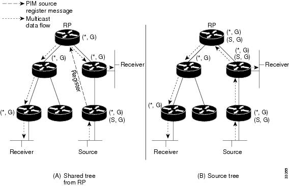

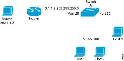
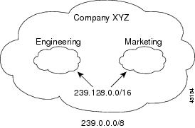
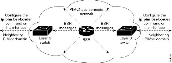
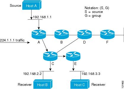
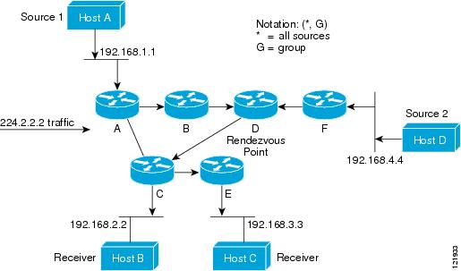
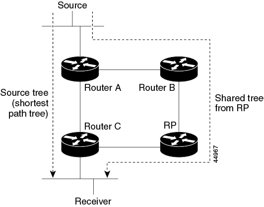
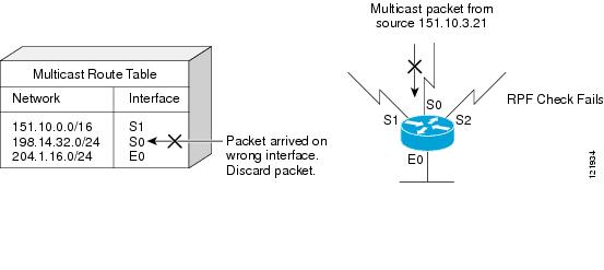
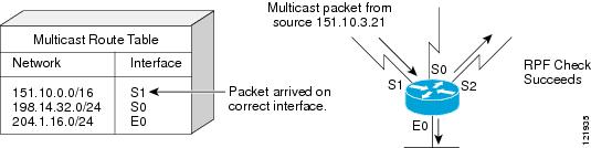
 Feedback