Information About IEEE 802.1Q Tunneling
The IEEE 802.1Q Tunneling feature is designed for service providers who carry traffic of multiple customers across their networks and are required to maintain the VLAN and Layer 2 protocol configurations of each customer without impacting the traffic of other customers.
IEEE 802.1Q Tunnel Ports in a Service Provider Network
Business customers of service providers often have specific requirements for VLAN IDs and the number of VLANs to be supported. The VLAN ranges required by different customers in the same service-provider network might overlap, and traffic of customers through the infrastructure might be mixed. Assigning a unique range of VLAN IDs to each customer would restrict customer configurations and could easily exceed the VLAN limit (4096) of the IEEE 802.1Q specification.
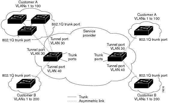
Using the IEEE 802.1Q tunneling feature, service providers can use a single VLAN to support customers who have multiple VLANs. Customer VLAN IDs are preserved, and traffic from different customers is segregated within the service-provider network, even when they appear to be in the same VLAN. Using IEEE 802.1Q tunneling expands VLAN space by using a VLAN-in-VLAN hierarchy and retagging the tagged packets. A port configured to support IEEE 802.1Q tunneling is called a tunnel port. When you configure tunneling, you assign a tunnel port to a VLAN ID that is dedicated to tunneling. Each customer requires a separate service-provider VLAN ID, but that VLAN ID supports all of the customer’s VLANs.
Customer traffic tagged in the normal way with appropriate VLAN IDs comes from an IEEE 802.1Q trunk port on the customer device and into a tunnel port on the service-provider edge device. The link between the customer device and the edge device is asymmetric because one end is configured as an IEEE 802.1Q trunk port, and the other end is configured as a tunnel port. You assign the tunnel port interface to an access VLAN ID that is unique to each customer.
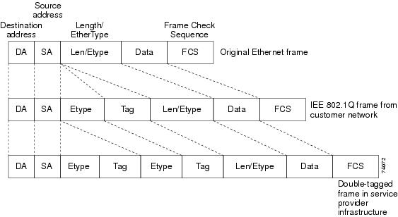
Packets coming from the customer trunk port into the tunnel port on the service-provider edge device are normally IEEE 802.1Q-tagged with the appropriate VLAN ID. The tagged packets remain intact inside the device and when they exit the trunk port into the service-provider network, they are encapsulated with another layer of an IEEE 802.1Q tag (called the metro tag) that contains the VLAN ID that is unique to the customer. The original customer IEEE 802.1Q tag is preserved in the encapsulated packet. Therefore, packets entering the service-provider network are double-tagged, with the outer (metro) tag containing the customer’s access VLAN ID, and the inner VLAN ID being that of the incoming traffic.
When the double-tagged packet enters another trunk port in a service-provider core device, the outer tag is stripped as the device processes the packet. When the packet exits another trunk port on the same core device, the same metro tag is again added to the packet.
When the packet enters the trunk port of the service-provider egress device, the outer tag is again stripped as the device internally processes the packet. However, the metro tag is not added when the packet is sent out the tunnel port on the edge device into the customer network. The packet is sent as a normal IEEE 802.1Q-tagged frame to preserve the original VLAN numbers in the customer network.
In the above network figure, Customer A was assigned VLAN 30, and Customer B was assigned VLAN 40. Packets entering the edge device tunnel ports with IEEE 802.1Q tags are double-tagged when they enter the service-provider network, with the outer tag containing VLAN ID 30 or 40, appropriately, and the inner tag containing the original VLAN number, for example, VLAN 100. Even if both Customers A and B have VLAN 100 in their networks, the traffic remains segregated within the service-provider network because the outer tag is different. Each customer controls its own VLAN numbering space, which is independent of the VLAN numbering space used by other customers and the VLAN numbering space used by the service-provider network.
At the outbound tunnel port, the original VLAN numbers on the customer’s network are recovered. It is possible to have multiple levels of tunneling and tagging, but the device supports only one level in this release.
If traffic coming from a customer network is not tagged (native VLAN frames), these packets are bridged or routed as normal packets. All packets entering the service-provider network through a tunnel port on an edge device are treated as untagged packets, whether they are untagged or already tagged with IEEE 802.1Q headers. The packets are encapsulated with the metro tag VLAN ID (set to the access VLAN of the tunnel port) when they are sent through the service-provider network on an IEEE 802.1Q trunk port. The priority field on the metro tag is set to the interface class of service (CoS) priority configured on the tunnel port. (The default is zero if none is configured.)
On devices, because 802.1Q tunneling is configured on a per-port basis, it does not matter whether the device is a standalone device or a stack member. All configuration is done on the stack master.
Native VLANs
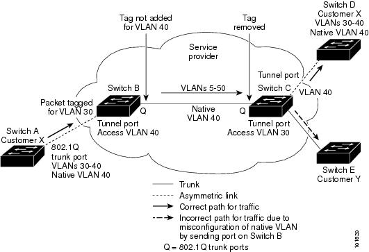
When configuring IEEE 802.1Q tunneling on an edge device, you must use IEEE 802.1Q trunk ports for sending packets into the service-provider network. However, packets going through the core of the service-provider network can be carried through IEEE 802.1Q trunks, ISL trunks, or nontrunking links. When IEEE 802.1Q trunks are used in these core devices, the native VLANs of the IEEE 802.1Q trunks must not match any native VLAN of the nontrunking (tunneling) port on the same device because traffic on the native VLAN would not be tagged on the IEEE 802.1Q sending trunk port.
In the following network figure, VLAN 40 is configured as the native VLAN for the IEEE 802.1Q trunk port from Customer X at the ingress edge device in the service-provider network (Device B). Device A of Customer X sends a tagged packet on VLAN 30 to the ingress tunnel port of Device B in the service-provider network, which belongs to access VLAN 40. Because the access VLAN of the tunnel port (VLAN 40) is the same as the native VLAN of the edge device trunk port (VLAN 40), the metro tag is not added to tagged packets received from the tunnel port. The packet carries only the VLAN 30 tag through the service-provider network to the trunk port of the egress-edgedevice (Device C) and is misdirected through the egress device tunnel port to Customer Y.
-
Use the vlan dot1q tag native global configuration command to configure the edge devices so that all packets going out an IEEE 802.1Q trunk, including the native VLAN, are tagged. If the devices is configured to tag native VLAN packets on all IEEE 802.1Q trunks, the devices accepts untagged packets, but sends only tagged packets.
-
Ensure that the native VLAN ID on the edge devices trunk port is not within the customer VLAN range. For example, if the trunk port carries traffic of VLANs 100 to 200, assign the native VLAN a number outside that range.
System MTU
The default system MTU for traffic on the device is 1500 bytes.
You can configure 10-Gigabit and Gigabit Ethernet ports to support frames larger than 1500 bytes by using the system mtu bytes global configuration command.
The system MTU and system jumbo MTU values do not include the IEEE 802.1Q header. Because the IEEE 802.1Q tunneling feature increases the frame size by 4 bytes when the metro tag is added, you must configure all devices in the service-provider network to be able to process maximum frames by adding 4 bytes to the system MTU size.
For example, the device supports a maximum frame size of 1496 bytes with this configuration: The device has a system MTU value of 1500 bytes, and the switchport mode dot1q tunnel interface configuration command is configured on a 10-Gigabit or Gigabit Ethernet device port.
IEEE 802.1Q Tunneling and Other Features
Although IEEE 802.1Q tunneling works well for Layer 2 packet switching, there are incompatibilities between some Layer 2 features and Layer 3 switching.
-
A tunnel port cannot be a routed port.
-
IP routing is not supported on a VLAN that includes IEEE 802.1Q tunnel ports. Packets received from a tunnel port are forwarded based only on Layer 2 information. If routing is enabled on a switch virtual interface (SVI) that includes tunnel ports, untagged IP packets received from the tunnel port are recognized and routed by the switch. Customers can access the Internet through its native VLAN. If this access is not needed, you should not configure SVIs on VLANs that include tunnel ports.
-
Fallback bridging is not supported on tunnel ports. Because all IEEE 802.1Q-tagged packets received from a tunnel port are treated as non-IP packets, if fallback bridging is enabled on VLANs that have tunnel ports configured, IP packets would be improperly bridged across VLANs. Therefore, you must not enable fallback bridging on VLANs with tunnel ports.
-
Tunnel ports do not support IP access control lists (ACLs).
-
Layer 3 quality of service (QoS) ACLs and other QoS features related to Layer 3 information are not supported on tunnel ports. MAC-based QoS is supported on tunnel ports.
-
EtherChannel port groups are compatible with tunnel ports as long as the IEEE 802.1Q configuration is consistent within an EtherChannel port group.
-
Port Aggregation Protocol (PAgP), Link Aggregation Control Protocol (LACP), and UniDirectional Link Detection (UDLD) are supported on IEEE 802.1Q tunnel ports.
-
Dynamic Trunking Protocol (DTP) is not compatible with IEEE 802.1Q tunneling because you must manually configure asymmetric links with tunnel ports and trunk ports.
-
VLAN Trunking Protocol (VTP) does not work between devices that are connected by an asymmetrical link or devices that communicate through a tunnel.
-
Loopback detection is supported on IEEE 802.1Q tunnel ports.
-
When a port is configured as an IEEE 802.1Q tunnel port, spanning-tree bridge protocol data unit (BPDU) filtering is automatically enabled on the interface. Cisco Discovery Protocol (CDP) and the Layer Link Discovery Protocol (LLDP) are automatically disabled on the interface.
-
When an IEEE 802.1Q tunnel port is configured as SPAN source, span filter must be applied for SVLAN to avoid packet loss.
-
IGMP/MLD packet forwarding can be enabled on IEEE 802.1Q tunnels. This can be done by disabling IGMP/MLD snooping on the service provider network.
Default IEEE 802.1Q Tunneling Configuration
By default, IEEE 802.1Q tunneling is disabled because the default switchport mode is dynamic auto. Tagging of IEEE 802.1Q native VLAN packets on all IEEE 802.1Q trunk ports is also disabled.
 Feedback