Configuring VPLS
This section provides information about the steps to configure VPLS:
Information About VPLS
VPLS Overview
VPLS (Virtual Private LAN Service) enables enterprises to link together their Ethernet-based LANs from multiple sites via the infrastructure provided by their service provider. From the enterprise perspective, the service provider's public network looks like one giant Ethernet LAN. For the service provider, VPLS provides an opportunity to deploy another revenue-generating service on top of their existing network without major capital expenditures. Operators can extend the operational life of equipment in their network.
Virtual Private LAN Services (VPLS) uses the provider core to join multiple attachment circuits together to simulate a virtual bridge that connects the multiple attachment circuits together. From a customer point of view, there is no topology for VPLS. All of the CE devices appear to connect to a logical bridge emulated by the provider core.
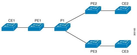
Full-Mesh Configuration
The full-mesh configuration requires a full mesh of tunnel label switched paths (LSPs) between all the PEs that participate in the VPLS. With full-mesh, signaling overhead and packet replication requirements for each provisioned VC on a PE can be high.
You set up a VPLS by first creating a virtual forwarding instance (VFI) on each participating PE router. The VFI specifies the VPN ID of a VPLS domain, the addresses of other PE devices in the domain, and the type of tunnel signaling and encapsulation mechanism for each peer PE router.
The set of VFIs formed by the interconnection of the emulated VCs is called a VPLS instance; it is the VPLS instance that forms the logic bridge over a packet switched network. The VPLS instance is assigned a unique VPN ID.
The PE devices use the VFI to establish a full-mesh LSP of emulated VCs to all the other PE devices in the VPLS instance. PE devices obtain the membership of a VPLS instance through static configuration using the Cisco IOS CLI.
The full-mesh configuration allows the PE router to maintain a single broadcast domain. Thus, when the PE router receives a broadcast, multicast, or unknown unicast packet on an attachment circuit, it sends the packet out on all other attachment circuits and emulated circuits to all other CE devices participating in that VPLS instance. The CE devices see the VPLS instance as an emulated LAN.
To avoid the problem of a packet looping in the provider core, the PE devices enforce a "split-horizon" principle for the emulated VCs. That means if a packet is received on an emulated VC, it is not forwarded on any other emulated VC.
After the VFI has been defined, it needs to be bound to an attachment circuit to the CE device.
The packet forwarding decision is made by looking up the Layer 2 virtual forwarding instance (VFI) of a particular VPLS domain.
A VPLS instance on a particular PE router receives Ethernet frames that enter on specific physical or logical ports and populates a MAC table similarly to how an Ethernet switch works. The PE router can use the MAC address to switch those frames into the appropriate LSP for delivery to the another PE router at a remote site.
If the MAC address is not in the MAC address table, the PE router replicates the Ethernet frame and floods it to all logical ports associated with that VPLS instance, except the ingress port where it just entered. The PE router updates the MAC table as it receives packets on specific ports and removes addresses not used for specific periods.
VPLS BGP Based Autodiscovery
VPLS Autodiscovery enables each Virtual Private LAN Service (VPLS) provider edge (PE) device to discover other PE devices that are part of the same VPLS domain. VPLS Autodiscovery also tracks PE devices when they are added to or removed from a VPLS domain. As a result, with VPLS Autodiscovery enabled, you no longer need to manually configure a VPLS domain and maintain the configuration when a PE device is added or deleted. VPLS Autodiscovery uses the Border Gateway Protocol (BGP) to discover VPLS members and set up and tear down pseudowires in a VPLS domain
BGP uses the Layer 2 VPN (L2VPN) Routing Information Base (RIB) to store endpoint provisioning information, which is updated each time any Layer 2 virtual forwarding instance (VFI) is configured. The prefix and path information is stored in the L2VPN database, which allows BGP to make decisions about the best path. When BGP distributes the endpoint provisioning information in an update message to all its BGP neighbors, this endpoint information is used to configure a pseudowire mesh to support L2VPN-based services.
The BGP autodiscovery mechanism facilitates the configuration of L2VPN services, which are an integral part of the VPLS feature. VPLS enables flexibility in deploying services by connecting geographically dispersed sites as a large LAN over high-speed Ethernet in a robust and scalable IP Multiprotocol Label Switching (MPLS) network.
Restrictions for VPLS
-
Protocol-based CLI Method (interface pseudowire configuration) is not supported. Only VFI and Xconnect mode are supported.
-
Flow-Aware Transport Pseudowire (FAT PW) is not supported.
-
IGMP Snooping is not Supported. Multicast traffic floods with IGMP Snooping disabled.
-
L2 Protocol Tunneling is not supported.
-
Integrated Routing and Bridging (IRB) not supported.
-
Virtual Circuit Connectivity Verification (VCCV) ping with explicit null is not supported.
-
The switch is supported only as spoke in H-VPLS but not as hub.
-
L2 VPN Interworking is not supported.
-
ip unnumbered command is not supported in MPLS configuration.
-
VC statistics are not displayed for flood traffic in the output of show mpls l2 vc vcid detail command.
-
dot1q tunnel is not supported in the attachment circuit.
Configuring PE Layer 2 Interfaces to CEs
This section provides information about configuring PE Layer 2 Interfaces to CEs:
Configuring 802.1Q Trunks for Tagged Traffic from a CE
SUMMARY STEPS
- enable
- configure terminal
- interface interface-id
- no ip address ip_address mask [secondary ]
- switchport
- switchport trunk encapsulation dot1q
- switchport trunk allow vlan vlan_ID
- switchport mode trunk
- end
DETAILED STEPS
| Command or Action | Purpose | |
|---|---|---|
| Step 1 |
enable Example: |
Enables privileged EXEC mode.
|
| Step 2 |
configure terminal Example: |
Enters global configuration mode. |
| Step 3 |
interface interface-id Example: |
Defines the interface to be configured as a trunk, and enters interface configuration mode. |
| Step 4 |
no ip address ip_address mask [secondary ] Example: |
Disables IP processing and enters interface configuration mode. |
| Step 5 |
switchport Example: |
Modifies the switching characteristics of the Layer 2-switched interface. |
| Step 6 |
switchport trunk encapsulation dot1q Example: |
Sets the switch port encapsulation format to 802.1Q. |
| Step 7 |
switchport trunk allow vlan vlan_ID Example: |
Sets the list of allowed VLANs. |
| Step 8 |
switchport mode trunk Example: |
Sets the interface to a trunking VLAN Layer 2 interface. |
| Step 9 |
end Example: |
Returns to privileged EXEC mode. |
Configuring 802.1Q Access Ports for Untagged Traffic from a CE
SUMMARY STEPS
- enable
- configure terminal
- interface interface-id
- no ip address ip_address mask [secondary ]
- switchport
- switchport mode access
- switchport access vlan vlan_ID
- end
DETAILED STEPS
| Command or Action | Purpose | |
|---|---|---|
| Step 1 |
enable Example: |
Enables privileged EXEC mode.
|
| Step 2 |
configure terminal Example: |
Enters global configuration mode. |
| Step 3 |
interface interface-id Example: |
Defines the interface to be configured as a trunk, and enters interface configuration mode. |
| Step 4 |
no ip address ip_address mask [secondary ] Example: |
Disables IP processing and enters interface configuration mode. |
| Step 5 |
switchport Example: |
Modifies the switching characteristics of the Layer 2-switched interface. |
| Step 6 |
switchport mode access Example: |
Sets the interface type to nontrunking, nontagged single VLAN Layer 2 interface. |
| Step 7 |
switchport access vlan vlan_ID Example: |
Sets the VLAN when the interface is in access mode. |
| Step 8 |
end Example: |
Returns to privileged EXEC mode. |
Configuring Layer 2 VLAN Instances on a PE
Configuring the Layer 2 VLAN interface on the PE enables the Layer 2 VLAN instance on the PE router to the VLAN database to set up the mapping between the VPLS and VLANs.
SUMMARY STEPS
- enable
- configure terminal
- vlan vlan-id
- interface vlan vlan-id
- end
DETAILED STEPS
| Command or Action | Purpose | |
|---|---|---|
| Step 1 |
enable Example: |
Enables privileged EXEC mode.
|
| Step 2 |
configure terminal Example: |
Enters global configuration mode. |
| Step 3 |
vlan vlan-id Example: |
Configures a specific virtual LAN (VLAN). |
| Step 4 |
interface vlan vlan-id Example: |
Configures an interface on the VLAN. |
| Step 5 |
end Example: |
Returns to privileged EXEC mode. |
Configuring MPLS in the PE
To configure MPLS in the PE, you must provide the required MPLS parameters.
SUMMARY STEPS
- enable
- configure terminal
- mpls ip
- mpls label protocol ldp
- end
- mpls ldp logging neighbor-changes
DETAILED STEPS
| Command or Action | Purpose | |
|---|---|---|
| Step 1 |
enable Example: |
Enables privileged EXEC mode.
|
| Step 2 |
configure terminal Example: |
Enters global configuration mode. |
| Step 3 |
mpls ip Example: |
Configures MPLS hop-by-hop forwarding. |
| Step 4 |
mpls label protocol ldp Example: |
Specifies the default Label Distribution Protocol for a platform. |
| Step 5 |
end Example: |
Returns to privileged EXEC mode. |
| Step 6 |
mpls ldp logging neighbor-changes Example: |
(Optional) Determines logging neighbor changes. |
Configuring VFI in the PE
The virtual switch instance (VFI) specifies the VPN ID of a VPLS domain, the addresses of other PE devices in this domain, and the type of tunnel signaling and encapsulation mechanism for each peer (This is where you create the VFI and associated VCs.). Configure a VFI as follows:
SUMMARY STEPS
- enable
- configure terminal
- l2 vfi vfi-name manual
- vpn id vpn-id
- neighbor remote-router-id {encapsulation mpls}
- end
DETAILED STEPS
| Command or Action | Purpose | |||
|---|---|---|---|---|
| Step 1 |
enable Example: |
Enables privileged EXEC mode.
|
||
| Step 2 |
configure terminal Example: |
Enters global configuration mode. |
||
| Step 3 |
l2 vfi vfi-name manual Example: |
Enables the Layer 2 VFI manual configuration mode. |
||
| Step 4 |
vpn id vpn-id Example: |
Configures a VPN ID for a VPLS domain. The emulated VCs bound to this Layer 2 VRF use this VPN ID for signaling.
|
||
| Step 5 |
neighbor remote-router-id {encapsulation mpls} Example: |
Specifies the remote peering router ID and the tunnel encapsulation type or the pseudo-wire property to be used to set up the emulated VC. |
||
| Step 6 |
end Example: |
Returns to privileged EXEC mode. |
Associating the Attachment Circuit with the VFI at the PE
After defining the VFI, you must bind it to one or more attachment circuits.
SUMMARY STEPS
- enable
- configure terminal
- interface vlan vlan-id
- no ip address
- xconnect vfi vfi-name
- end
DETAILED STEPS
| Command or Action | Purpose | |||
|---|---|---|---|---|
| Step 1 |
enable Example: |
Enables privileged EXEC mode.
|
||
| Step 2 |
configure terminal Example: |
Enters global configuration mode. |
||
| Step 3 |
interface vlan vlan-id Example: |
Creates or accesses a dynamic switched virtual interface (SVI).
|
||
| Step 4 |
no ip address Example: |
Disables IP processing. (You configure a Layer 3 interface for the VLAN if you configure an IP address.) |
||
| Step 5 |
xconnect vfi vfi-name Example: |
Specifies the Layer 2 VFI that you are binding to the VLAN port. |
||
| Step 6 |
end Example: |
Returns to privileged EXEC mode. |
Configuration Examples for VPLS
|
PE1 Configuration |
PE2 Configuration |
|---|---|
|
|
Local interface: VFI 2129 vfi up
  Interworking type is Ethernet
  Destination address: 44.254.44.44, VC ID: 2129, VC status: up
    Output interface: Gi1/0/9, imposed label stack {18 17}
    Preferred path: not configured
    Default path: active
    Next hop: 177.77.177.2
  Create time: 19:09:33, last status change time: 09:24:14
    Last label FSM state change time: 09:24:14
  Signaling protocol: LDP, peer 44.254.44.44:0 up
    Targeted Hello: 1.1.1.72(LDP Id) -> 44.254.44.44, LDP is UP
    Graceful restart: configured and enabled
    Non stop routing: not configured and not enabled
    Status TLV support (local/remote)   : enabled/supported
      LDP route watch                   : enabled
      Label/status state machine        : established, LruRru
      Last local dataplane   status rcvd: No fault
Last BFD dataplane     status rcvd: Not sent
      Last BFD peer monitor  status rcvd: No fault
      Last local AC  circuit status rcvd: No fault
      Last local AC  circuit status sent: No fault
      Last local PW i/f circ status rcvd: No fault
      Last local LDP TLV     status sent: No fault
      Last remote LDP TLV    status rcvd: No fault
      Last remote LDP ADJ    status rcvd: No fault
MPLS VC labels: local 512, remote 17
    Group ID: local n/a, remote 0
    MTU: local 1500, remote 1500
    Remote interface description:
  Sequencing: receive disabled, send disabled
  Control Word: Off
  SSO Descriptor: 44.254.44.44/2129, local label: 512
  Dataplane:
    SSM segment/switch IDs: 20498/20492 (used), PWID: 2
  VC statistics:
    transit packet totals: receive 0, send 0
    transit byte totals:   receive 0, send 0
    transit packet drops:  receive 0, seq error 0, send 0
pseudowire100005 is up, VC status is up PW type: Ethernet
  Create time: 19:25:56, last status change time: 09:40:37
    Last label FSM state change time: 09:40:37
  Destination address: 44.254.44.44 VC ID: 2129
    Output interface: Gi1/0/9, imposed label stack {18 17}
    Preferred path: not configured
    Default path: active
    Next hop: 177.77.177.2
  Member of vfi service 2129
    Bridge-Domain id: 2129
    Service id: 0x32000003
  Signaling protocol: LDP, peer 44.254.44.44:0 up
    Targeted Hello: 1.1.1.72(LDP Id) -> 44.254.44.44, LDP is UP
    Graceful restart: configured and enabled
    Non stop routing: not configured and not enabled
     PWid FEC (128), VC ID: 2129
    Status TLV support (local/remote)         : enabled/supported
      LDP route watch                         : enabled
      Label/status state machine              : established, LruRru
      Local dataplane status received         : No fault
      BFD dataplane status received           : Not sent
      BFD peer monitor status received        : No fault
      Status received from access circuit     : No fault
      Status sent to access circuit           : No fault
      Status received from pseudowire i/f     : No fault
Status sent to network peer             : No fault
      Status received from network peer       : No fault
      Adjacency status of remote peer         : No fault
  Sequencing: receive disabled, send disabled
  Bindings
    Parameter    Local                          Remote
    ------------ ------------------------------ ------------------------------
    Label        512                            17
    Group ID     n/a                            0
    Interface
    MTU          1500                           1500
    Control word off                            off
    PW type      Ethernet                       Ethernet
    VCCV CV type 0x02                           0x02
                   LSPV [2]                       LSPV [2]
    VCCV CC type 0x06                           0x06
                   RA [2], TTL [3]               RA [2], TTL [3]
    Status TLV   enabled                        supported
  SSO Descriptor: 44.254.44.44/2129, local label: 512
  Dataplane:
    SSM segment/switch IDs: 20498/20492 (used), PWID: 2
  Rx Counters
    0 input transit packets, 0 bytes
    0 drops, 0 seq err
  Tx Counters
    0 output transit packets, 0 bytes
0 drops Feedback