Configuring MPLS VPN-Inter-AS-IPv4 BGP Label Distribution

MPLS VPN Inter-AS IPv4 BGP Label Distribution

This feature enables you to set up a Virtual Private Network (VPN) service provider network. In this network, the Autonomous System Boundary Routers (ASBRs) exchange IPv4 routes with Multiprotocol Label Switching (MPLS) labels of the provider edge (PE) routers. Route reflectors (RRs) exchange VPNv4 routes by using multihop, multiprotocol, External Border Gateway Protocol (EBGP). This configuration saves the ASBRs from having to store all the VPNv4 routes. Using the route reflectors to store the VPNv4 routes and forward them to the PE routers results in improved scalability.

The MPLS VPN—Inter-AS—IPv4 BGP Label Distribution feature has the following benefits:

  • Having the route reflectors store VPNv4 routes results in improved scalability—This configuration scales better than configurations where the ASBR holds all the VPNv4 routes and forwards the routes based on VPNv4 labels. With this configuration, route reflectors hold the VPNv4 route, which simplifies the configuration at the border of the network.

  • Enables a non-VPN core network to act as a transit network for VPN traffic—You can transport IPv4 routes with MPLS labels over a non MPLS VPN service provider.

  • Eliminates the need for any other label distribution protocol between adjacent LSRs—If two adjacent label switch routers (LSRs) are also BGP peers, BGP can handle the distribution of the MPLS labels. No other label distribution protocol is needed between the two LSRs.

  • Includes EBGP multipath support to enable load balancing for IPv4 routes across autonomous system (AS) boundaries.
Restrictions for MPLS VPN Inter-AS IPv4 BGP Label Distribution

This feature includes the following restrictions:

  • For networks configured with EBGP multihop, a labeled switched path (LSP) must be established between nonadjacent devices. (RFC 3107)

  • The PE devices must run images that support BGP label distribution. Otherwise, you cannot run EBGP between them.

  • Point-to-Point Protocol (PPP) encapsulation on the ASBRs is not supported with this feature.

  • The physical interfaces that connect the BGP speakers must support Cisco Express Forwarding (CEF) or distributed CEF and MPLS

Information About MPLS VPN Inter-AS IPv4 BGP Label Distribution

To configure MPLS VPN Inter-AS IPv4 BGP Label Distribution, you need the following information:

MPLS VPN Inter-AS IPv4 BGP Label Distribution Overview

This feature enables you to set up a VPN service provider network to exchange IPv4 routes with MPLS labels. You can configure the VPN service provider network as follows:

  • Route reflectors exchange VPNv4 routes by using multihop, multiprotocol EBGP. This configuration also preserves the next hop information and the VPN labels across the autonomous systems.

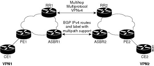
  • A local PE router (for example, PE1 in Figure 1) needs to know the routes and label information for the remote PE router (PE2). This information can be exchanged between the PE routers and ASBRs in one of two ways:

    • Internal Gateway Protocol (IGP) and Label Distribution Protocol (LDP): The ASBR can redistribute the IPv4 routes and MPLS labels it learned from EBGP into IGP and LDP and vice versa.

    • Internal Border Gateway Protocol (IBGP) IPv4 label distribution: The ASBR and PE router can use direct IBGP sessions to exchange VPNv4 and IPv4 routes and MPLS labels.

    Alternatively, the route reflector can reflect the IPv4 routes and MPLS labels learned from the ASBR to the PE routers in the VPN. This is accomplished by enabling the ASBR to exchange IPv4 routes and MPLS labels with the route reflector. The route reflector also reflects the VPNv4 routes to the PE routers in the VPN (as mentioned in the first bullet). For example, in VPN1, RR1 reflects to PE1 the VPNv4 routes it learned and IPv4 routes and MPLS labels learned from ASBR1. Using the route reflectors to store the VPNv4 routes and forward them through the PE routers and ASBRs allows for a scalable configuration.

  • ASBRs exchange IPv4 routes and MPLS labels for the PE routers by using EBGP. This enables load balancing across CSC boundaries.

Figure 1. VPNs Using EBGP and IBGP to Distribute Routes and MPLS Labels

BGP Routing Information

BGP routing information includes the following items:

  • A network number (prefix), which is the IP address of the destination.

  • Autonomous system (AS) path, which is a list of the other ASs through which a route passes on its way to the local router. The first autonomous system in the list is closest to the local router. The last autonomous system in the list is farthest from the local router and usually the autonomous system where the route began.

  • Path attributes, which provide other information about the autonomous system path, for example, the next hop.

How BGP Sends MPLS Labels with Routes

When BGP (EBGP and IBGP) distributes a route, it can also distribute an MPLS label that is mapped to that route. The MPLS label-mapping information for the route is carried in the BGP update message that contains the information about the route. If the next hop is not changed, the label is preserved.

When you issue the neighbor send-label command on both BGP routers, the routers advertise to each other that they can then send MPLS labels with the routes. If the routers successfully negotiate their ability to send MPLS labels, the routers add MPLS labels to all outgoing BGP updates.

Using Route Maps to Filter Routes

When both routers are configured to distribute routes with MPLS labels, all the routes are encoded with the multiprotocol extensions and contain an MPLS label. You can use a route map to control the distribution of MPLS labels between routers. Route maps enable you to specify the following:

  • For a router distributing MPLS labels, you can specify which routes are distributed with an MPLS label.

  • For a router receiving MPLS labels, you can specify which routes are accepted and installed in the BGP table.

How to Configure MPLS VPN Inter-AS IPv4 BGP Label Distribution

The figure below shows the following configuration:

  • The configuration consists of two VPNs.

  • The ASBRs exchange the IPv4 routes with MPLS labels.

  • The route reflectors exchange the VPNv4 routes using multi-hop MPLS EBGP.

  • The route reflectors reflect the IPv4 and VPNv4 routes to the other routers in its autonomous system.

Figure 2. Configuring Two VPN Service Providers to Exchange IPv4 Routes and MPLS Labels

Configuring the ASBRs to Exchange IPv4 Routes and MPLS Labels

Perform this task to configure the ASBRs so that they can distribute BGP routes with MPLS labels.

SUMMARY STEPS

  1. enable
  2. configure terminal
  3. router bgp as-number
  4. neighbor { ip-address| peer-group-name} remote-as as-number
  5. address-family ipv4 [ multicast| unicast| vrfvrf-name]
  6. maximum-paths number-paths
  7. neighbor { ip-address| peer-group-name} activate
  8. neighbor ip-addresssend-label
  9. exit-address-family
  10. end

DETAILED STEPS

  Command or Action Purpose

Step 1

enable

Example:


Device> enable

Enables privileged EXEC mode.

  • Enter your password if prompted.

Step 2

configure terminal

Example:


Device# configure terminal

Enters global configuration mode.

Step 3

router bgp as-number

Example:

Device(config)# router bgp 100

Enters router configuration mode.

  • as-number—Number of an autonomous system that identifies the router to other BGP routers and tags the routing information that is passed along. The valid values range from 1 through 65535. Private autonomous system numbers that can be used in internal networks range from 64512 through 65535.

Step 4

neighbor { ip-address| peer-group-name} remote-as as-number

Example:

Device(config)# neighbor 209.165.201.2 remote-as 200

Adds an entry to the BGP or multiprotocol BGP neighbor table.

  • The ip-address argument specifies the IP address of the neighbor.

  • The peer-group-nameargument specifies the name of a BGP peer group.

  • The as-number argument specifies the autonomous system to which the neighbor belongs.

Step 5

address-family ipv4 [ multicast| unicast| vrfvrf-name]

Example:

Device(config-router)# address-family ipv4

Enters address family configuration mode for configuring routing sessions such as BGP that use standard IPv4 address prefixes.

  • The multicast keyword specifies IPv4 multicast address prefixes.

  • The unicast keyword specifies IPv4 unicast address prefixes.

  • The vrf vrf-name keyword and argument specifies the name of the VPN routing/forwarding instance (VRF) to associate with subsequent IPv4 address family configuration mode commands.

Step 6

maximum-paths number-paths

Example:

Device(config-router)# maximum-paths 2

(Optional) Controls the maximum number of parallel routes an IP routing protocol can support.

The number-paths argument specifies the maximum number of parallel routes an IP routing protocol installs in a routing table, in the range from 1 through 6.

Note


The valid values of the maximum-paths command range from 1 to 32. However, the maximum value that can be configured is 2.

Step 7

neighbor { ip-address| peer-group-name} activate

Example:

Device(config-router-af)# neighbor 209.165.201.2 activate

Enables the exchange of information with a neighboring router.

  • The ip-address argument specifies the IP address of the neighbor.

  • The peer-group-name argument specifies the name of a BGP peer group.

Step 8

neighbor ip-addresssend-label

Example:

Device(config-router-af)# neighbor 10.0.0.1 send-label

Enables a BGP router to send MPLS labels with BGP routes to a neighboring BGP router.

  • The ip-address argument specifies the IP address of the neighboring router.

Step 9

exit-address-family

Example:

Device(config-router-af)# exit-address-family

Exits from the address family submode.

Step 10

end

Example:

Device(config-router-af)# end

(Optional) Exits to privileged EXEC mode.

Configuring the Route Reflectors to Exchange VPNv4 Routes

Before you begin

Perform this task to enable the route reflectors to exchange VPNv4 routes by using multihop, multiprotocol EBGP.

This procedure also specifies that the next hop information and the VPN label are preserved across the autonomous systems. This procedure uses RR1 as an example.

SUMMARY STEPS

  1. enable
  2. configure terminal
  3. router bgp as-number
  4. neighbor { ip-address| peer-group-name} remote-as as-number
  5. address-family vpnv4[ unicast]
  6. neighbor { ip-address| peer-group-name} ebgp-multihop [ ttl]
  7. neighbor { ip-address| peer-group-name} activate
  8. neighbor { ip-address| peer-group-name} next-hop unchanged
  9. exit-address-family
  10. end

DETAILED STEPS

  Command or Action Purpose

Step 1

enable

Example:


Device> enable

Enables privileged EXEC mode.

  • Enter your password if prompted.

Step 2

configure terminal

Example:


Device# configure terminal

Enters global configuration mode.

Step 3

router bgp as-number

Example:

Device(config)# router bgp 100

Enters router configuration mode.

  • as-number—Number of an autonomous system that identifies the router to other BGP routers and tags the routing information that is passed along. The valid values range from 1through 65535. Private autonomous system numbers that can be used in internal networks range from 64512 through 65535.

    The autonomous system number identifies RR1 to routers in other autonomous systems.

Step 4

neighbor { ip-address| peer-group-name} remote-as as-number

Example:

Device(config)# neighbor 192.0.2.1 remote-as 200

Adds an entry to the BGP or multiprotocol BGP neighbor table.

  • The ip-address argument specifies the IP address of the neighbor.

  • The peer-group-nameargument specifies the name of a BGP peer group.

  • The as-number argument specifies the autonomous system to which the neighbor belongs.

Step 5

address-family vpnv4[ unicast]

Example:

Device(config-router)# address-family vpnv4

Enters address family configuration mode for configuring routing sessions, such as BGP, that uses standard Virtual Private Network Version 4 (VPNv4) address prefixes.

  • The optional unicast keyword specifies VPNv4 unicast address prefixes.

Step 6

neighbor { ip-address| peer-group-name} ebgp-multihop [ ttl]

Example:

Device(config-router-af)# neighbor 192.0.2.1 ebgp-multihop 255 

Accepts and attempts BGP connections to external peers residing on networks that are not directly connected.

  • The ip-address argument specifies the IP address of the BGP-speaking neighbor.

  • The peer-group-name argument specifies the name of a BGP peer group.

  • Thettl argument specifies the time-to-live in the range from 1 through 255 hops.

Step 7

neighbor { ip-address| peer-group-name} activate

Example:

Device(config-router-af)# neighbor 192.0.2.1 activate

Enables the exchange of information with a neighboring router.

  • The ip-address argument specifies the IP address of the neighbor.

  • The peer-group-name argument specifies the name of a BGP peer group.

Step 8

neighbor { ip-address| peer-group-name} next-hop unchanged

Example:

Device(config-router-af)# neighbor 10.0.0.2 next-hop unchanged

Enables an External BGP (EBGP) multihop peer to propagate the next hop unchanged.

  • The ip-address argument specifies the IP address of the next hop.

  • The peer-group-name argument specifies the name of a BGP peer group that is the next hop.

Step 9

exit-address-family

Example:

Device(config-router-af)# exit-address-family

Exits from the address family submode.

Step 10

end

Example:

Device(config-router-af)# end

(Optional) Exits to privileged EXEC mode.

Configuring the Route Reflectors to Reflect Remote Routes in Its autonomous system

Perform this task to enable the RR to reflect the IPv4 routes and labels that are learned by the ASBR to the PE routers in the autonomous system.

This is accomplished by making the ASBR and PE router the route reflector clients of the RR. This procedure also explains how to enable the RR to reflect the VPNv4 routes.

SUMMARY STEPS

  1. enable
  2. configure terminal
  3. router bgp as-number
  4. address-family ipv4 [ multicast| unicast| vrfvrf-name]
  5. neighbor { ip-address| peer-group-name} activate
  6. neighborip-addressroute-reflector-client
  7. neighborip-addresssend-label
  8. exit-address-family
  9. address-family vpnv4 [ unicast]
  10. neighbor { ip-address| peer-group-name} activate
  11. neighbor ip-address route-reflector-client
  12. exit-address-family
  13. end

DETAILED STEPS

  Command or Action Purpose

Step 1

enable

Example:


Device> enable

Enables privileged EXEC mode.

  • Enter your password if prompted.

Step 2

configure terminal

Example:


Device# configure terminal

Enters global configuration mode.

Step 3

router bgp as-number

Example:

Device(config)# router bgp 100

Enters router configuration mode.

  • as-number—Number of an autonomous system that identifies the router to other BGP routers and tags the routing information that is passed along. The valid values range from 1 through 65535. Private autonomous system numbers that can be used in internal networks range from 64512 through 65535.

    The autonomous system number identifies RR1 to routers in other autonomous systems.

Step 4

address-family ipv4 [ multicast| unicast| vrfvrf-name]

Example:

Device(config-router)# address-family ipv4

Enters address family configuration mode for configuring routing sessions, such as BGP, that use standard IPv4 address prefixes.

  • The multicast keyword specifies IPv4 multicast address prefixes.

  • The unicast keyword specifies IPv4 unicast address prefixes.

  • The vrf vrf-name keyword and argument specifies the name of the VPN routing/forwarding instance (VRF) to associate with subsequent IPv4 address family configuration mode commands.

Step 5

neighbor { ip-address| peer-group-name} activate

Example:

Device(config-router-af)# neighbor 203.0.113.1 activate

Enables the exchange of information with a neighboring router.

  • The ip-address argument specifies the IP address of the neighbor.

  • The peer-group-name argument specifies the name of a BGP peer group.

Step 6

neighborip-addressroute-reflector-client

Example:

Device(config-router-af)# neighbor 203.0.113.1 route-reflector-client

Configures the router as a BGP route reflector and configures the specified neighbor as its client.

  • The ip-address argument specifies the IP address of the BGP neighbor being identified as a client.

Step 7

neighborip-addresssend-label

Example:

Device(config-router-af)# neighbor 203.0.113.1 send-label

Enables a BGP router to send MPLS labels with BGP routes to a neighboring BGP router.

  • The ip-address argument specifies the IP address of the neighboring router.

Step 8

exit-address-family

Example:

Device(config-router-af)# exit-address-family

Exits from the address family submode.

Step 9

address-family vpnv4 [ unicast]

Example:

Device(config-router)# address-family vpnv4

Enters address family configuration mode for configuring routing sessions, such as BGP, that use standard VPNv4 address prefixes.

  • The optional unicast keyword specifies VPNv4 unicast address prefixes.

Step 10

neighbor { ip-address| peer-group-name} activate

Example:

Device(config-router-af)# neighbor 203.0.113.1 activate

Enables the exchange of information with a neighboring router.

  • The ip-address argument specifies the IP address of the neighbor.

  • The peer-group-name argument specifies the name of a BGP peer group.

Step 11

neighbor ip-address route-reflector-client

Example:

Device(config-router-af)# neighbor 203.0.113.1 route-reflector-client

Enables the RR to pass IBGP routes to the neighboring router.

Step 12

exit-address-family

Example:

Device(config-router-af)# exit-address-family

Exits from the address family submode.

Step 13

end

Example:

Device(config-router-af)# end

(Optional) Exits to privileged EXEC mode.

Creating Route Maps

Route maps enable you to specify which routes are distributed with MPLS labels. Route maps also enable you to specify which routes with MPLS labels a router receives and adds to its BGP table.

Route maps work with access lists. You enter the routes into an access list and then specify the access list when you configure the route map.

The following procedures enable the ASBRs to send MPLS labels with the routes specified in the route maps. Further, the ASBRs accept only the routes that are specified in the route map.

Configuring a Route Map for Arriving Routes

Perform this task to create a route map to filter arriving routes. You create an access list and specify the routes that the router accepts and adds to the BGP table.

SUMMARY STEPS

  1. enable
  2. configure terminal
  3. router bgp as-number
  4. route-map route-map name [ permit| deny] [ sequence-number]
  5. match ip address { access-list-number| access-list-name} [ ...access-list-number| ...access-list-name]
  6. match mpls-label
  7. end

DETAILED STEPS

  Command or Action Purpose

Step 1

enable

Example:


Device> enable

Enables privileged EXEC mode.

  • Enter your password if prompted.

Step 2

configure terminal

Example:


Device# configure terminal

Enters global configuration mode.

Step 3

router bgp as-number

Example:

Device(config)# router bgp 100

Enters router configuration mode.

  • as-number—Number of an autonomous system that identifies the router to other BGP routers and tags the routing information that is passed along. The valid values range from 1 through 65535. Private autonomous system numbers that can be used in internal networks range from 64512 through 65535.

    The autonomous system number identifies RR1 to routers in other autonomous systems.

Step 4

route-map route-map name [ permit| deny] [ sequence-number]

Example:

Device(config-router)# route-map IN permit 11

Creates a route map with the name you specify.

  • The permit keyword allows the actions to happen if all conditions are met.

  • The deny keyword prevents any actions from happening if all conditions are met.

  • The sequence-number argument allows you to prioritize route maps. If you have multiple route maps and want to prioritize them, assign each one a number. The route map with the lowest number is implemented first, followed by the route map with the second lowest number, and so on.

Step 5

match ip address { access-list-number| access-list-name} [ ...access-list-number| ...access-list-name]

Example:

Device(config-route-map)# match ip address 2

Distributes any routes that have a destination network number address that is permitted by a standard or extended access list, or performs policy routing on packets.

  • The access-list-number argument is a number of a standard or extended access list. It can be an integer from 1 through 199.

  • The access-list-name argument is a name of a standard or extended access list. It can be an integer from 1 through 199.

Step 6

match mpls-label

Example:

Device(config-route-map)# match mpls-label

Redistributes routes that include MPLS labels if the routes meet the conditions that are specified in the route map.

Step 7

end

Example:

Device(config-router-af)# end

(Optional) Exits to privileged EXEC mode.

Configuring a Route Map for Departing Routes

Perform this task to create a route map to filter departing routes. You create an access list and specify the routes that the router distributes with MPLS labels.

SUMMARY STEPS

  1. enable
  2. configure terminal
  3. router bgp as-number
  4. route-map route-map name [ permit| deny] [ sequence-number]
  5. match ip address { access-list-number| access-list-name} [ ...access-list-number| ...access-list-name]
  6. set mpls-label
  7. end

DETAILED STEPS

  Command or Action Purpose

Step 1

enable

Example:


Device> enable

Enables privileged EXEC mode.

  • Enter your password if prompted.

Step 2

configure terminal

Example:


Device# configure terminal

Enters global configuration mode.

Step 3

router bgp as-number

Example:

Device(config)# router bgp 100

Enters router configuration mode.

  • as-number—Number of an autonomous system that identifies the router to other BGP routers and tags the routing information that is passed along. The valid values range from 1 through 65535. Private autonomous system numbers that can be used in internal networks range from 64512 through 65535.

    The AS number identifies RR1 to routers in other autonomous systems.

Step 4

route-map route-map name [ permit| deny] [ sequence-number]

Example:

Device(config-router)# route-map OUT permit 10

Creates a route map with the name you specify.

  • The permit keyword allows the actions to happen if all conditions are met.

  • The deny keyword prevents any actions from happening if all conditions are met.

  • The sequence-number argument allows you to prioritize route maps. If you have multiple route maps and want to prioritize them, assign each one a number. The route map with the lowest number is implemented first, followed by the route map with the second lowest number, and so on.

Step 5

match ip address { access-list-number| access-list-name} [ ...access-list-number| ...access-list-name]

Example:

Device(config-route-map)# match 10.0.0.2 1

Distributes any routes that have a destination network number address that is permitted by a standard or extended access list, or performs policy routing on packets.

  • The access-list-number argument is a number of a standard or extended access list. It can be an integer from 1 through 199.

  • The access-list-name argument is a name of a standard or extended access list. It can be an integer from 1 through 199.

Step 6

set mpls-label

Example:

Device(config-route-map)# set mpls-label

Enables a route to be distributed with an MPLS label if the route matches the conditions that are specified in the route map.

Step 7

end

Example:

Device(config-router-af)# end

(Optional) Exits to privileged EXEC mode.

Applying the Route Maps to the ASBRs

Perform this task to enable the ASBRs to use the route maps.

SUMMARY STEPS

  1. enable
  2. configure terminal
  3. router bgp as-number
  4. address-family ipv4 [ multicast| unicast| vrfvrf-name]
  5. neighborip-addressroute-maproute-map-nameout
  6. neighbor ip-address send-label
  7. exit-address-family
  8. end

DETAILED STEPS

  Command or Action Purpose

Step 1

enable

Example:


Device> enable

Enables privileged EXEC mode.

  • Enter your password if prompted.

Step 2

configure terminal

Example:


Device# configure terminal

Enters global configuration mode.

Step 3

router bgp as-number

Example:

Device(config)# router bgp 100

Enters router configuration mode.

  • as-number—Number of an autonomous system that identifies the router to other BGP routers and tags the routing information that is passed along. The valid values range from 1 through 65535. Private autonomous system numbers that can be used in internal networks range from 64512 through 65535.

    The autonomous system number identifies RR1 to routers in other autonomous systems.

Step 4

address-family ipv4 [ multicast| unicast| vrfvrf-name]

Example:

Device(config-router)# address-family ipv4

Enters address family configuration mode for configuring routing sessions such as BGP that use standard IPv4 address prefixes.

  • The multicast keyword specifies IPv4 multicast address prefixes.

  • The unicast keyword specifies IPv4 unicast address prefixes.

  • The vrf vrf-name keyword and argument specifies the name of the VPN routing/forwarding instance (VRF) to associate with subsequent IPv4 address family configuration mode commands.

Step 5

neighborip-addressroute-maproute-map-nameout

Example:

Device(config-router-af)# neighbor 209.165.200.225 route-map OUT out

Applies a route map to incoming routes.

  • The ip-address argument specifies the device to which the route map is to be applied.

  • The route-map-name argument specifies the name of the route map.

  • The out keyword applies the route map to outgoing routes.

Step 6

neighbor ip-address send-label

Example:

Device(config-router-af)# neighbor 209.165.200.225 send-label

Advertises the ability of the router to send MPLS labels with routes.

  • The ip-address argument specifies the router that is enabled to send MPLS labels with routes.

Step 7

exit-address-family

Example:

Device(config-router-af)# exit-address-family

Exits from the address family submode.

Step 8

end

Example:

Device(config-router-af)# end

(Optional) Exits to privileged EXEC mode.

Verifying the MPLS VPN Inter-AS IPv4 BGP Label Distribution Configuration

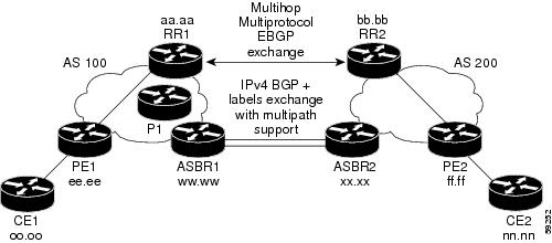
The following figure is a reference for the configuration.

Figure 3. Configuring Two VPN Service Providers to Exchange IPv4 Routes and MPLS Labels

If you use route reflectors to distribute the VPNv4 routes and use the ASBRs to distribute the IPv4 labels, use the following procedures to help verify the configuration:

Verifying the Route Reflector Configuration

Perform this task to verify the route reflector configuration.

SUMMARY STEPS

  1. enable
  2. show ip bgp vpnv4 { all | rd route-distinguisher| vrf vrf-name} [ summary] [ labels]
  3. disable

DETAILED STEPS

  Command or Action Purpose

Step 1

enable

Example:


Device> enable

Enables privileged EXEC mode.

  • Enter your password if prompted.

Step 2

show ip bgp vpnv4 { all | rd route-distinguisher| vrf vrf-name} [ summary] [ labels]

Example:

Device# show ip bgp vpnv4 all summary

Example:

Device# show ip bgp vpnv4 all labels

(Optional) Displays VPN address information from the BGP table.

  • Use the show ip bgp vpnv4 command with the all and summary keywords to verify that a multihop, multiprotocol, EBGP session exists between the route reflectors and that the VPNv4 routes are being exchanged between the route reflectors.

  • The last two lines of the command output show the following information:

    • Prefixes are being learned from PE1 and then passed to RR2.

    • Prefixes are being learned from RR2 and then passed to PE1.

  • Use the show ip bgp vpnv4 command with the all and labels keywords to verify that the route reflectors are exchanging VPNv4 label information.

Step 3

disable

Example:

Device# disable

(Optional) Exits to user EXEC mode.

Verifying that CE1 Has Network Reachability Information for CE2

Perform this task to verify that router CE1 has NLRI for router CE2.

SUMMARY STEPS

  1. enable
  2. show ip route [ ip-address [ mask] [ longer prefixes] ] | [ protocol [ process-id] ] | [ list access-list-number| access-list-name]
  3. disable

DETAILED STEPS

  Command or Action Purpose

Step 1

enable

Example:


Device> enable

Enables privileged EXEC mode.

  • Enter your password if prompted.

Step 2

show ip route [ ip-address [ mask] [ longer prefixes] ] | [ protocol [ process-id] ] | [ list access-list-number| access-list-name]

Example:

Device# show ip route 209.165.201.1

Displays the current state of the routing table.

  • Use the show ip route command with the ip-address argument to verify that CE1 has a route to CE2.

  • Use the show ip route command to verify the routes learned by CE1. Make sure to list the route for CE2.

Step 3

disable

Example:

Device# disable

(Optional) Exits to user EXEC mode.

Verifying that PE1 Has Network Layer Reachability Information for CE2

Perform this task to verify that router PE1 has NLRI for router CE2.

SUMMARY STEPS

  1. enable
  2. show ip route vrf vrf-name [ connected] [ protocols [ as-number] [ tag] [ output-modifiers] ] [ list number[ output-modifiers] ] [ profile] [ static[ output-modifiers] ] [summary [ output-modifiers] ] [supernets-only [ output-modifiers] ] [ traffic engineering [ output-modifiers] ]
  3. show ip bgp vpnv4 { all | rd route-distinguisher| vrf vrf-name} { ip-prefix/length [ longer-prefixes] [ output-modifiers] ] [ network-address [ mask] [ longer-prefixes] [ output-modifiers] ] [ cidr-only] [ community] [ community-list] [ dampened-paths] [ filter-list] [ flap-statistics] [ inconsistent-as] [ neighbors] [ path[ line] ] [ peer-group] [ quote-regexp] [ regexp] [ summary] [ tags]
  4. show ip cef [ vrf vrf-name] [ network [ mask] ] [ longer-prefixes] [ detail]
  5. show mpls forwarding-table [ { network { mask| length} | labels label[ -label] | interface interface| next-hop address| lsp-tunnel [ tunnel-id] } ] [ detail]
  6. show ip bgp [ network] [ network-mask] [ longer-prefixes]
  7. show ip bgp vpnv4 { all| rd route-distinguisher| vrf vrf-name} [ summary] [ labels]
  8. disable

DETAILED STEPS

  Command or Action Purpose

Step 1

enable

Example:


Device> enable

Enables privileged EXEC mode.

  • Enter your password if prompted.

Step 2

show ip route vrf vrf-name [ connected] [ protocols [ as-number] [ tag] [ output-modifiers] ] [ list number[ output-modifiers] ] [ profile] [ static[ output-modifiers] ] [summary [ output-modifiers] ] [supernets-only [ output-modifiers] ] [ traffic engineering [ output-modifiers] ]

Example:

Device# show ip route vrf vpn1 209.165.201.1

(Optional) Displays the IP routing table that is associated with a VRF.

  • Use the show ip route vrf command to verify that router PE1 learns routes from router CE2 (nn.nn.nn.nn).

Step 3

show ip bgp vpnv4 { all | rd route-distinguisher| vrf vrf-name} { ip-prefix/length [ longer-prefixes] [ output-modifiers] ] [ network-address [ mask] [ longer-prefixes] [ output-modifiers] ] [ cidr-only] [ community] [ community-list] [ dampened-paths] [ filter-list] [ flap-statistics] [ inconsistent-as] [ neighbors] [ path[ line] ] [ peer-group] [ quote-regexp] [ regexp] [ summary] [ tags]

Example:

Device# show ip bgp vpnv4 vrf vpn1 209.165.201.1

(Optional) Displays VPN address information from the BGP table.

  • Use the show ip bgp vpnv4 command with the vrf or all keyword to verify that router PE2 is the BGP next-hop to router CE2.

Step 4

show ip cef [ vrf vrf-name] [ network [ mask] ] [ longer-prefixes] [ detail]

Example:

Device# show ip cef vrf vpn1 209.165.201.1

(Optional) Displays entries in the forwarding information base (FIB) or displays a summary of the FIB.

  • Use the show ip cef command to verify that the Cisco Express Forwarding (CEF) entries are correct.

Step 5

show mpls forwarding-table [ { network { mask| length} | labels label[ -label] | interface interface| next-hop address| lsp-tunnel [ tunnel-id] } ] [ detail]

Example:

Device# show mpls forwarding-table

(Optional) Displays the contents of the MPLS forwarding information base (LFIB).

  • Use the show mpls forwarding-table command to verify the IGP label for the BGP next hop router (autonomous system boundary).

Step 6

show ip bgp [ network] [ network-mask] [ longer-prefixes]

Example:

Device# show ip bgp 209.165.202.129

(Optional) Displays entries in the BGP routing table.

  • Use the show ip bgp command to verify the label for the remote egress PE router (PE2).

Step 7

show ip bgp vpnv4 { all| rd route-distinguisher| vrf vrf-name} [ summary] [ labels]

Example:

Device# show ip bgp vpnv4 all labels

(Optional) Displays VPN address information from the BGP table.

  • Use the show ip bgp vpnv4 all summary command to verify the VPN label of CE2, as advertised by PE2.

Step 8

disable

Example:

Device# disable

(Optional) Exits to user EXEC mode.

Verifying that PE2 Has Network Reachability Information for CE2

Perform this task to ensure that PE2 can access CE2.

SUMMARY STEPS

  1. enable
  2. show ip route vrf vrf-name [ connected] [ protocol [ as-number] [ tag] [ output-modifiers] ] [ list number [ output-modifiers] ] [ profile] [ static[ output-modifiers] ] [ summary [ output-modifiers] ] [ supernets-only [ output-modifiers] ] [ traffic-engineering [ output-modifiers] ]
  3. show mpls forwarding-table [ vrf vpn-name] [ { network { mask | length } | labels label[ -label] | interface interface | next-hop address | lsp-tunnel [ tunnel-id ] } ] [ detail]
  4. show ip bgp vpnv4 { all | rd route-distinguisher | vrf vrf-name} [ summary] [ labels]
  5. show ip cef [ vrf vrf-name ] [ network [ mask] ] [ longer-prefixes] [ detail]
  6. disable

DETAILED STEPS

  Command or Action Purpose

Step 1

enable

Example:


Device> enable

Enables privileged EXEC mode.

  • Enter your password if prompted.

Step 2

show ip route vrf vrf-name [ connected] [ protocol [ as-number] [ tag] [ output-modifiers] ] [ list number [ output-modifiers] ] [ profile] [ static[ output-modifiers] ] [ summary [ output-modifiers] ] [ supernets-only [ output-modifiers] ] [ traffic-engineering [ output-modifiers] ]

Example:

Device# show ip route vrf vpn1 209.165.201.1

(Optional) Displays the IP routing table that is associated with a VRF.

  • Use the show ip route vrf command to check the VPN routing and forwarding table for CE2. The output provides next hop information.

Step 3

show mpls forwarding-table [ vrf vpn-name] [ { network { mask | length } | labels label[ -label] | interface interface | next-hop address | lsp-tunnel [ tunnel-id ] } ] [ detail]

Example:

Device# show mpls forwarding-table vrf vpn1 209.165.201.1

(Optional) Displays the contents of the LFIB.

  • Use the show mpls forwarding-table command with the vrf keyword to check the VPN routing and forwarding table for CE2. The output provides the label for CE2 and the outgoing interface.

Step 4

show ip bgp vpnv4 { all | rd route-distinguisher | vrf vrf-name} [ summary] [ labels]

Example:

Device# show ip bgp vpnv4 all labels

(Optional) Displays VPN address information from the BGP table.

  • Use the show ip bgp vpnv4 command with the all and labels keywords to check the VPN label for CE2 in the multiprotocol BGP table.

Step 5

show ip cef [ vrf vrf-name ] [ network [ mask] ] [ longer-prefixes] [ detail]

Example:

Device# show ip cef <vrf-name> 209.165.201.1

(Optional) Displays entries in the forwarding information base (FIB) or displays a summary of the FIB.

  • Use the show ip cef command to check the CEF entry for CE2. The command output shows the local label for CE2 and the outgoing interface.

Step 6

disable

Example:

Device# disable

(Optional) Exits to user EXEC mode.

Verifying the ASBR Configuration

Perform this task to verify that the ASBRs exchange IPv4 routes with MPLS labels or IPv4 routes without labels as prescribed by a route map.

SUMMARY STEPS

  1. enable
  2. show ip bgp [ network] [ network-mask] [ longer-prefixes]
  3. show ip cef [ vrf vrf-name] [ network [ mask] ] [ longer-prefixes] [ detail]
  4. disable

DETAILED STEPS

  Command or Action Purpose

Step 1

enable

Example:


Device> enable

Enables privileged EXEC mode.

  • Enter your password if prompted.

Step 2

show ip bgp [ network] [ network-mask] [ longer-prefixes]

Example:

Device# show ip bgp 209.165.202.129

Example:

Device# show ip bgp 192.0.2.1

(Optional) Displays entries in the BGP routing table.

  • Use the show ip bgp command to verify that

    • ASBR1 receives an MPLS label for PE2 from ASBR2.

    • ASBR1 received from ASBR2 IPv4 routes for RR2 without labels. If the command output does not display the MPLS label information, the route was received without an MPLS label.

    • ASBR2 distributes an MPLS label for PE2 to ASBR1.

    • ASBR2 does not distribute a label for RR2 to ASBR1.

Step 3

show ip cef [ vrf vrf-name] [ network [ mask] ] [ longer-prefixes] [ detail]

Example:

Device# show ip cef 209.165.202.129

Example:

Device# show ip cef 192.0.2.1

(Optional) Displays entries in the forwarding information base (FIB) or displays a summary of the FIB.

  • Use the show ip cef command from ASBR1 and ASBR2 to check that

    • The CEF entry for PE2 is correct.

    • The CEF entry for RR2 is correct.

Step 4

disable

Example:

Device# disable

(Optional) Exits to the user EXEC mode.

Configuration Examples for MPLS VPN Inter-AS IPv4 BGP Label Distribution

Configuration examples for MPLS VPN Inter-AS IPv4 BGP Label Distribution feature include the following:

Configuration Examples for Inter-AS Using BGP to Distribute Routes and MPLS Labels Over an MPLS VPN Service Provider

The figure shows two MPLS VPN service providers. The service provider distributes the VPNv4 routes between the route reflectors. They distribute the IPv4 routes with MPLS labels between the ASBRs.

Figure 4. Distributing IPv4 Routes and MPLS Labels Between MPLS VPN Service Providers

The configuration examples show the two techniques that you can use to distribute the VPNv4 routes and the IPv4 routes with MPLS labels, from the remote RRs and PEs to the local RRs and PEs:

  • Autonomous system 100 uses the RRs to distribute the VPNv4 routes learned from the remote RRs. The RRs also distribute the remote PE address and label that is learned from ASBR1 using IPv4 + labels.

  • In autonomous system 200, the IPv4 routes that ASBR2 learned are redistributed into IGP.

The configuration examples in this section are as follow:

Example: Route Reflector 1 (MPLS VPN Service Provider)

The configuration example for RR1 specifies the following:

  • RR1 exchanges VPNv4 routes with RR2 using multiprotocol, multihop EBGP.

  • The VPNv4 next hop information and the VPN label preserved across the autonomous systems.

  • RR1 reflects to PE1:

    • The VPNv4 routes learned from RR2.

    • The IPv4 routes and MPLS labels learned from ASBR1

ip subnet-zero
 ip cef
 !
 interface Loopback0
  ip address 10.0.0.1 255.255.255.255
  no ip directed-broadcast
 !
 interface Serial1/2
  ip address 209.165.201.8 255.0.0.0
  no ip directed-broadcast
  clockrate 124061
 !   
 router ospf 10
  log-adjacency-changes
  auto-cost reference-bandwidth 1000
  network 10.0.0.1 0.0.0.0 area 100
  network 209.165.201.9 0.255.255.255 area 100
!
 router bgp 100
  bgp cluster-id 1
  bgp log-neighbor-changes
  timers bgp 10 30
  neighbor 203.0.113.1 remote-as 100
  neighbor 203.0.113.1 update-source Loopback0
  neighbor 209.165.200.225 remote-as 100
  neighbor 209.165.200.225 update-source Loopback0
  neighbor 192.0.2.1 remote-as 200
  neighbor 192.0.2.1 ebgp-multihop 255
  neighbor 192.0.2.1 update-source Loopback0
  no auto-summary
  !
 address-family ipv4
  neighbor 203.0.113.1 activate
  neighbor 203.0.113.1 route-reflector-client                !IPv4+labels session to PE1
  neighbor 203.0.113.1 send-label
  neighbor 209.165.200.225 activate
  neighbor 209.165.200.225 route-reflector-client                !IPv4+labels session to ASBR1
  neighbor 209.165.200.225 send-label
  no neighbor 192.0.2.1 activate
  no auto-summary
  no synchronization
  exit-address-family
  !
 address-family vpnv4
  neighbor 203.0.113.1 activate
  neighbor 203.0.113.1 route-reflector-client                !VPNv4 session with PE1
  neighbor 203.0.113.1 send-community extended
  neighbor 192.0.2.1 activate             
  neighbor 192.0.2.1 next-hop-unchanged                    !MH-VPNv4 session with RR2
  neighbor 192.0.2.1 send-community extended                 !with next hop unchanged     
  exit-address-family
 !
 ip default-gateway 3.3.0.1
 no ip classless
 !
 snmp-server engineID local 00000009020000D0584B25C0
 snmp-server community public RO
 snmp-server community write RW
 no snmp-server ifindex persist
 snmp-server packetsize 2048
 !
 end

Configuration Example: ASBR1 (MPLS VPN Service Provider)

ASBR1 exchanges IPv4 routes and MPLS labels with ASBR2.

In this example, ASBR1 uses route maps to filter routes.

  • A route map called OUT specifies that ASBR1 should distribute the PE1 route (ee.ee) with labels and the RR1 route (aa.aa) without labels.

  • A route map called IN specifies that ASBR1 should accept the PE2 route (ff.ff) with labels and the RR2 route (bb.bb) without labels.

ip subnet-zero
 mpls label protocol tdp
 !
 interface Loopback0
  ip address 209.165.200.225 255.255.255.255
  no ip directed-broadcast
  no ip route-cache
  no ip mroute-cache
 !
 interface Ethernet0/2
  ip address 209.165.201.6 255.0.0.0
  no ip directed-broadcast
  no ip mroute-cache
 !
 interface Ethernet0/3
  ip address 209.165.201.18 255.0.0.0
  no ip directed-broadcast
  no ip mroute-cache
  mpls label protocol ldp
  mpls ip
 !router ospf 10
  log-adjacency-changes
  auto-cost reference-bandwidth 1000
  redistribute connected subnets
  passive-interface Ethernet0/2
  network 209.165.200.225 0.0.0.0 area 100
  network 209.165.201.9 0.255.255.255 area 100
  
 router bgp 100
  bgp log-neighbor-changes
  timers bgp 10 30
  neighbor 10.0.0.1 remote-as 100
  neighbor 10.0.0.1 update-source Loopback0
  neighbor 209.165.201.2 remote-as 200
  no auto-summary
  !
 address-family ipv4                       ! Redistributing IGP into BGP 
  redistribute ospf 10                     ! so that PE1 & RR1 loopbacks 
  neighbor 10.0.0.1 activate            ! get into the BGP table
  neighbor 10.0.0.1 send-label
  neighbor 209.165.201.2 activate
  neighbor 209.165.201.2 advertisement-interval 5
  neighbor 209.165.201.2 send-label
  neighbor 209.165.201.2 route-map IN in        ! accepting routes in route map IN.
  neighbor 209.165.201.2 route-map OUT out      ! distributing routes in route map OUT.
  neighbor 209.165.201.3 activate
  neighbor 209.165.201.3 advertisement-interval 5
  neighbor 209.165.201.3 send-label
  neighbor 209.165.201.3 route-map IN in        ! accepting routes in route map IN.
  neighbor 209.165.201.3 route-map OUT out      ! distributing routes in route map OUT.
  no auto-summary
  no synchronization
  exit-address-family
 !
 ip default-gateway 3.3.0.1
 ip classless
 !
 access-list 1 permit 203.0.113.1 log                !Setting up the access lists
 access-list 2 permit 209.165.202.129 log
 access-list 3 permit 10.0.0.1 log
 access-list 4 permit 192.0.2.1 log

 route-map IN permit 10                              !Setting up the route maps
  match ip address 2
  match mpls-label
 !
 route-map IN permit 11
  match ip address 4
 !
 route-map OUT permit 12
  match ip address 3
 !
 route-map OUT permit 13
  match ip address 1
  set mpls-label
 !
 end

Configuration Example: Route Reflector 2 (MPLS VPN Service Provider)

RR2 exchanges VPNv4 routes with RR1 through multihop, multiprotocol EBGP. This configuration also specifies that the next hop information and the VPN label are preserved across the autonomous systems.

ip subnet-zero
 ip cef
 !
 interface Loopback0
  ip address 192.0.2.1 255.255.255.255
  no ip directed-broadcast
 !
 interface Serial1/1
  ip address 209.165.201.10 255.0.0.0
  no ip directed-broadcast
  no ip mroute-cache
 !
 router ospf 20
  log-adjacency-changes
  network 192.0.2.1 0.0.0.0 area 200
  network 209.165.201.20 0.255.255.255 area 200
 !
router bgp 200
  bgp cluster-id 1
  bgp log-neighbor-changes
  timers bgp 10 30
  neighbor 10.0.0.1 remote-as 100
  neighbor 10.0.0.1 ebgp-multihop 255
  neighbor 10.0.0.1 update-source Loopback0
  neighbor 209.165.202.129 remote-as 200
  neighbor 209.165.202.129 update-source Loopback0
  no auto-summary
  !
  address-family vpnv4
  neighbor 10.0.0.1 activate
  neighbor 10.0.0.1 next-hop-unchanged              !Multihop VPNv4 session with RR1 
  neighbor 10.0.0.1 send-community extended              !with next-hop-unchanged
  neighbor 209.165.202.129 activate
  neighbor 209.165.202.129 route-reflector-client          !VPNv4 session with PE2
  neighbor 209.165.202.129 send-community extended
  exit-address-family
 !
 ip default-gateway 3.3.0.1
 no ip classless
 !
 end

Configuration Example: ASBR2 (MPLS VPN Service Provider)

ASBR2 exchanges IPv4 routes and MPLS labels with ASBR1. However, in contrast to ASBR1, ASBR2 does not use the RR to reflect IPv4 routes and MPLS labels to PE2. ASBR2 redistributes the IPv4 routes and MPLS labels learned from ASBR1 into IGP. PE2 can now reach these prefixes.

ip subnet-zero
 ip cef
 !
 mpls label protocol tdp
 !
 interface Loopback0
  ip address 209.165.200.226 255.255.255.255
  no ip directed-broadcast
 !
 interface Ethernet1/0
  ip address 209.165.201.2 255.0.0.0
  no ip directed-broadcast
  no ip mroute-cache
 !
 interface Ethernet1/2
  ip address 209.165.201.4 255.0.0.0
  no ip directed-broadcast
  no ip mroute-cache
  mpls label protocol tdp
  mpls ip
  !
router ospf 20
  log-adjacency-changes
  auto-cost reference-bandwidth 1000
  redistribute connected subnets
  redistribute bgp 200 subnets           ! Redistributing the routes learned from 
  passive-interface Ethernet1/0               ! ASBR1(EBGP+labels session) into IGP 
  network 209.165.200.226 0.0.0.0 area 200         ! so that PE2 will learn them  
  network 209.165.201.5 0.255.255.255 area 200
  !
 router bgp 200
  bgp log-neighbor-changes
  timers bgp 10 30
  neighbor 192.0.2.1 remote-as 200
  neighbor 192.0.2.1 update-source Loopback0
  neighbor 209.165.201.6 remote-as 100
  no auto-summary
  !
address-family ipv4
  redistribute ospf 20                         ! Redistributing IGP into BGP  
  neighbor 209.165.201.6 activate                   ! so that PE2 & RR2 loopbacks
  neighbor 209.165.201.6 advertisement-interval 5   ! will get into the BGP-4 table.
  neighbor 209.165.201.6 route-map IN in 
  neighbor 209.165.201.6 route-map OUT out
  neighbor 209.165.201.6 send-label
  neighbor 209.165.201.7 activate 
  neighbor 209.165.201.7 advertisement-interval 5 
  neighbor 209.165.201.7 route-map IN in 
  neighbor 209.165.201.7 route-map OUT out
  neighbor 209.165.201.7 send-label
  no auto-summary
  no synchronization
  exit-address-family
 ! 
 address-family vpnv4
  neighbor 192.0.2.1 activate
  neighbor 192.0.2.1 send-community extended
  exit-address-family
  !
ip default-gateway 3.3.0.1
 ip classless
 !
 access-list 1 permit 209.165.202.129 log          !Setting up the access lists
 access-list 2 permit 203.0.113.1 log
 access-list 3 permit 192.0.2.1 log
 access-list 4 permit 10.0.0.1 log

 route-map IN permit 11                       !Setting up the route maps
  match ip address 2
  match mpls-label
 !
 route-map IN permit 12
  match ip address 4
 !
 route-map OUT permit 10
  match ip address 1
  set mpls-label
 !
 route-map OUT permit 13
  match ip address 3
 end

Configuration Examples: Inter-AS Using BGP to Distribute Routes and MPLS Labels Over a Non MPLS VPN Service Provider

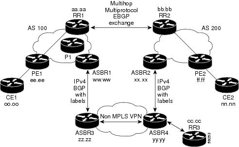
The figure shows two MPLS VPN service providers that are connected through a non MPLS VPN service provider. The autonomous system in the middle of the network is configured as a backbone autonomous system that uses Label Distribution Protocol (LDP) or Tag Distribution Protocol (TDP) to distribute MPLS labels. You can also use traffic engineering tunnels instead of TDP or LDP to build the LSP across the non MPLS VPN service provider.

Figure 5. Distributing Routes and MPLS Labels Over a Non MPLS VPN Service Provider

Configuration examples for Inter-AS using BGP to distribute routes and MPLS labels over a non MPLS VPN service provider included in this section are as follows:

Configuration Example: Route Reflector 1 (Non MPLS VPN Service Provider)

The configuration example for RR1 specifies the following:

  • RR1 exchanges VPNv4 routes with RR2 using multiprotocol, multihop EBGP.

  • The VPNv4 next hop information and the VPN label are preserved across the autonomous systems.

  • RR1 reflects to PE1:

    • The VPNv4 routes learned from RR2

    • The IPv4 routes and MPLS labels learned from ASBR1

ip subnet-zero
 ip cef
 !
 interface Loopback0
  ip address 10.0.0.1 255.255.255.255
  no ip directed-broadcast
 !
 interface Serial1/2
  ip address 209.165.201.8 255.0.0.0
  no ip directed-broadcast
  clockrate 124061
 !   
 router ospf 10
  log-adjacency-changes
  auto-cost reference-bandwidth 1000
  network 10.0.0.1 0.0.0.0 area 100
  network 209.165.201.9 0.255.255.255 area 100
 !
router bgp 100
  bgp cluster-id 1
  bgp log-neighbor-changes
  timers bgp 10 30
  neighbor 203.0.113.1 remote-as 100
  neighbor 203.0.113.1 update-source Loopback0
  neighbor 209.165.200.225 remote-as 100
  neighbor 209.165.200.225 update-source Loopback0
  neighbor 192.0.2.1 remote-as 200
  neighbor 192.0.2.1 ebgp-multihop 255
  neighbor 192.0.2.1 update-source Loopback0
  no auto-summary
  !
 address-family ipv4
  neighbor 203.0.113.1 activate
  neighbor 203.0.113.1 route-reflector-client                !IPv4+labels session to PE1
  neighbor 203.0.113.1 send-label
  neighbor 209.165.200.225 activate
  neighbor 209.165.200.225 route-reflector-client                !IPv4+labels session to ASBR1
  neighbor 209.165.200.225 send-label
  no neighbor 192.0.2.1 activate
  no auto-summary
  no synchronization
  exit-address-family
  !
address-family vpnv4
  neighbor 203.0.113.1 activate
  neighbor 203.0.113.1 route-reflector-client               !VPNv4 session with PE1
  neighbor 203.0.113.1 send-community extended
  neighbor 192.0.2.1 activate             
  neighbor 192.0.2.1 next-hop-unchanged                    !MH-VPNv4 session with RR2
  neighbor 192.0.2.1 send-community extended                 with next-hop-unchanged     
  exit-address-family
 !
 ip default-gateway 3.3.0.1
 no ip classless
 !
 snmp-server engineID local 00000009020000D0584B25C0
 snmp-server community public RO
 snmp-server community write RW
 no snmp-server ifindex persist
 snmp-server packetsize 2048
 !
 end

Configuration Example: ASBR1 (Non MPLS VPN Service Provider)

ASBR1 exchanges IPv4 routes and MPLS labels with ASBR2.

In this example, ASBR1 uses route maps to filter routes.

  • A route map called OUT specifies that ASBR1 should distribute the PE1 route (ee.ee) with labels and the RR1 route (aa.aa) without labels.

  • A route map called IN specifies that ASBR1 should accept the PE2 route (ff.ff) with labels and the RR2 route (bb.bb) without labels.

ip subnet-zero
 ip cef distributed
 mpls label protocol tdp
 !
 interface Loopback0
  ip address  209.165.200.225 255.255.255.255
  no ip directed-broadcast
  no ip route-cache
  no ip mroute-cache
 !
 interface Serial3/0/0
  ip address 209.165.201.7 255.0.0.0
  no ip directed-broadcast
  ip route-cache distributed
 !
 interface Ethernet0/3
  ip address 209.165.201.18 255.0.0.0
  no ip directed-broadcast
  no ip mroute-cache
  mpls label protocol ldp
  mpls ip
 !
router ospf 10
  log-adjacency-changes
  auto-cost reference-bandwidth 1000
  redistribute connected subnets
  passive-interface Serial3/0/0
  network  209.165.200.225 0.0.0.0 area 100
  network dd.0.0.0 0.255.255.255 area 100
  
 router bgp 100
  bgp log-neighbor-changes
  timers bgp 10 30
  neighbor 10.0.0.1 remote-as 100
  neighbor 10.0.0.1 update-source Loopback0
  neighbor kk.0.0.1 remote-as 200
  no auto-summary
 !
  address-family ipv4
  redistribute ospf 10                      ! Redistributing IGP into BGP  
  neighbor 10.0.0.1 activate             ! so that PE1 & RR1 loopbacks
  neighbor 10.0.0.1 send-label           ! get into BGP table
  neighbor 209.165.201.3 activate
  neighbor 209.165.201.3 advertisement-interval 5
  neighbor 209.165.201.3 send-label
  neighbor 209.165.201.3 route-map IN in    ! Accepting routes specified in route map IN
  neighbor 209.165.201.3 route-map OUT out  ! Distributing routes specified in route map OUT
  no auto-summary
  no synchronization
  exit-address-family
 !
 ip default-gateway 3.3.0.1
 ip classless
 !
 access-list 1 permit 203.0.113.1 log
 access-list 2 permit 209.165.202.129 log
 access-list 3 permit 10.0.0.1 log
 access-list 4 permit 192.0.2.1 log
 !
 route-map IN permit 10
  match ip address 2
  match mpls-label
 !
 route-map IN permit 11
  match ip address 4
 !
 route-map OUT permit 12
  match ip address 3
 !
 route-map OUT permit 13
  match ip address 1
  set mpls-label
 !
 end

Configuration Example: Route Reflector 2 (Non MPLS VPN Service Provider)

RR2 exchanges VPNv4 routes with RR1 using multihop, multiprotocol EBGP. This configuration also specifies that the next hop information and the VPN label are preserved across the autonomous systems.

ip subnet-zero
 ip cef
 ! 
 interface Loopback0
  ip address 192.0.2.1 255.255.255.255
  no ip directed-broadcast
 !
 interface Serial1/1
  ip address 209.165.201.10 255.0.0.0
  no ip directed-broadcast
  no ip mroute-cache
 !
 router ospf 20
  log-adjacency-changes
  network 192.0.2.1 0.0.0.0 area 200
  network 209.165.201.20 0.255.255.255 area 200
 !
router bgp 200
  bgp cluster-id 1
  bgp log-neighbor-changes
  timers bgp 10 30
  neighbor 10.0.0.1 remote-as 100
  neighbor 10.0.0.1 ebgp-multihop 255
  neighbor 10.0.0.1 update-source Loopback0
  neighbor 209.165.202.129 remote-as 200
  neighbor 209.165.202.129 update-source Loopback0
  no auto-summary
  !
  address-family vpnv4
  neighbor  10.0.0.1 activate
  neighbor  10.0.0.1 next-hop-unchanged              !MH vpnv4 session with RR1 
  neighbor  10.0.0.1 send-community extended              !with next-hop-unchanged
  neighbor  209.165.202.129 activate
  neighbor  209.165.202.129 route-reflector-client          !vpnv4 session with PE2
  neighbor  209.165.202.129 send-community extended
  exit-address-family
 !
 ip default-gateway 3.3.0.1
 no ip classless
 !
 end

Configuration Examples: ASBR2 (Non MPLS VPN Service Provider)

ASBR2 exchanges IPv4 routes and MPLS labels with ASBR1. However, in contrast to ASBR1, ASBR2 does not use the RR to reflect IPv4 routes and MPLS labels to PE2. ASBR2 redistributes the IPv4 routes and MPLS labels learned from ASBR1 into IGP. PE2 can now reach these prefixes.

ip subnet-zero
 ip cef
 !
 mpls label protocol tdp
 !
 interface Loopback0
  ip address 209.165.200.226 255.255.255.255
  no ip directed-broadcast
 !
 interface Ethernet0/1
  ip address 209.165.201.11 255.0.0.0
  no ip directed-broadcast
 !
 interface Ethernet1/2
  ip address 209.165.201.4 255.0.0.0
  no ip directed-broadcast
  no ip mroute-cache
  mpls label protocol tdp
  mpls ip
  !
 router ospf 20
  log-adjacency-changes
  auto-cost reference-bandwidth 1000
  redistribute connected subnets
  redistribute bgp 200 subnets            !redistributing the routes learned from 
  passive-interface Ethernet0/1                !ASBR2 (EBGP+labels session) into IGP 
  network 209.165.200.226 0.0.0.0 area 200         !so that PE2 will learn them  
  network 209.165.201.5 0.255.255.255 area 200
  !
 router bgp 200
  bgp log-neighbor-changes
  timers bgp 10 30
  neighbor 192.0.2.1 remote-as 200
  neighbor 192.0.2.1 update-source Loopback0
  neighbor 209.165.201.21 remote-as 100
  no auto-summary
 ! 
 address-family ipv4                          ! Redistributing IGP into BGP                                                                                 
redistribute ospf 20                         ! so that PE2 & RR2 loopbacks
  neighbor 209.165.201.21 activate                  !  will get into the BGP-4 table
  neighbor 209.165.201.21 advertisement-interval 5
  neighbor 209.165.201.21 route-map IN in
  neighbor 209.165.201.21 route-map OUT out
  neighbor 209.165.201.21 send-label
  no auto-summary
  no synchronization
  exit-address-family
  ! 
 address-family vpnv4
  neighbor 192.0.2.1 activate
  neighbor 192.0.2.1 send-community extended
  exit-address-family
  !
 ip default-gateway 3.3.0.1
 ip classless
 !
 access-list 1 permit 209.165.202.129 log
 access-list 2 permit 203.0.113.1 log
 access-list 3 permit 192.0.2.1 log
 access-list 4 permit 10.0.0.1 log
 !
 route-map IN permit 11
  match ip address 2
  match mpls-label
 !
 route-map IN permit 12
  match ip address 4
 !
 route-map OUT permit 10
  match ip address 1
  set mpls-label
 !
 route-map OUT permit 13
  match ip address 3
 !
 end

Configuration Example: ASBR3 (Non MPLS VPN Service Provider)

ASBR3 belongs to a non MPLS VPN service provider. ASBR3 exchanges IPv4 routes and MPLS labels with ASBR1. ASBR3 also passes the routes learned from ASBR1 to ASBR3 through RR3.


Note


Do not redistribute EBGP routes learned into IBG if you are using IBGP to distribute the routes and labels. This is not a supported configuration.


ip subnet-zero
 ip cef
 !
 interface Loopback0
  ip address 209.165.200.227 255.255.255.255
  no ip directed-broadcast
  no ip route-cache
  no ip mroute-cache
 !
 ip routing
mpls label protocol ldp
mpls ldp router-id Loopback0 force

interface GigabitEthernet1/0/1
ip address 209.165.201.12 255.0.0.0

interface TenGigabitEthernet1/1/1
no switchport
ip address 209.165.201.3 255.0.0.0
load-interval 30
mpls ip

 !
 router ospf 30
 log-adjacency-changes
 auto-cost reference-bandwidth 1000
 redistribute connected subnets
 network 209.165.200.227 0.0.0.0 area 300 
 network 209.165.201.13 0.255.255.255 area 300 
 !
 router bgp 300
  bgp log-neighbor-changes
  timers bgp 10 30
  neighbor 10.0.0.3 remote-as 300
  neighbor 10.0.0.3 update-source Loopback0
  neighbor 209.165.201.7 remote-as 100
  no auto-summary
  !
  address-family ipv4
  neighbor 10.0.0.3activate            ! IBGP+labels session with RR3
  neighbor 10.0.0.3 send-label
  neighbor 209.165.201.7 activate               ! EBGP+labels session with ASBR1
  neighbor 209.165.201.7 advertisement-interval 5
  neighbor 209.165.201.7 send-label
 neighbor 209.165.201.7 route-map IN in 
 neighbor 209.165.201.7 route-map OUT out 
 no auto-summary
  no synchronization
  exit-address-family
 !
 ip classless 
 ! 
 access-list 1 permit 203.0.113.1 log 
 access-list 2 permit 209.165.202.129 log 
 access-list 3 permit 10.0.0.1 log 
 access-list 4 permit 192.0.2.1 log 
 ! 
 route-map IN permit 10 
  match ip address 1 
   match mpls-label 
 ! 
 route-map IN permit 11 
    match ip address 3 
 ! 
 route-map OUT permit 12 
  match ip address 2 
   set mpls-label 
 ! 
 route-map OUT permit 13 
    match ip address 4 
 ! 
 ip default-gateway 3.3.0.1
 ip classless
 !
 end

Configuration Example: Route Reflector 3 (Non MPLS VPN Service Provider)

RR3 is a non MPLS VPN RR that reflects IPv4 routes with MPLS labels to ASBR3 and ASBR4.

ip subnet-zero
 mpls label protocol tdp
 mpls traffic-eng auto-bw timers
 no mpls ip
 !
 interface Loopback0
  ip address 10.0.0.3 255.255.255.255
  no ip directed-broadcast
 !
 interface POS0/2
  ip address 209.165.201.15 255.0.0.0
  no ip directed-broadcast
  no ip route-cache cef
  no ip route-cache
  no ip mroute-cache
  crc 16
  clock source internal
 !
 router ospf 30
  log-adjacency-changes
  network 10.0.0.3 0.0.0.0 area 300
  network 209.165.201.16 0.255.255.255 area 300
 !
 router bgp 300
  bgp log-neighbor-changes
  neighbor 209.165.201.2 remote-as 300
  neighbor 209.165.201.2 update-source Loopback0
  neighbor 209.165.200.227 remote-as 300
  neighbor 209.165.200.227 update-source Loopback0
  no auto-summary
  !
 address-family ipv4
  neighbor 209.165.201.2 activate
  neighbor 209.165.201.2 route-reflector-client   
  neighbor 209.165.201.2 send-label               ! IBGP+labels session with ASBR3 
  neighbor 209.165.200.227 activate                 
  neighbor 209.165.200.227 route-reflector-client
  neighbor 209.165.200.227 send-label               ! IBGP+labels session with ASBR4
  no auto-summary
  no synchronization
  exit-address-family
 !
 ip default-gateway 3.3.0.1
 ip classless
 !
 end 

Configuration Example: ASBR4 (Non MPLS VPN Service Provider)

ASBR4 belongs to a non MPLS VPN service provider. ASBR4 and ASBR3 exchange IPv4 routes and MPLS labels by means of RR3.


Note


Do not redistribute EBGP routes learned into IBG if you are using IBGP to distribute the routes and labels. This is not a supported configuration.


ip subnet-zero
 ip cef distributed
 !
 interface Loopback0
  ip address 209.165.201.2 255.255.255.255
  no ip directed-broadcast
  no ip route-cache
  no ip mroute-cache
 !
 interface Ethernet0/2
  ip address 209.165.201.21 255.0.0.0
  no ip directed-broadcast
  no ip mroute-cache
 !
 ip routing
mpls label protocol ldp
mpls ldp router-id Loopback0 force


interface GigabitEthernet1/0/1
ip address 209.165.201.17 255.0.0.0

interface TenGigabitEthernet1/1/1
no switchport
ip address 209.165.201.14 255.0.0.0
load-interval 30
mpls ip

 !
 router ospf 30
  log-adjacency-changes
  auto-cost reference-bandwidth 1000
  redistribute connected subnets
 passive-interface Ethernet0/2
  network 209.165.201.2 0.0.0.0 area 300
  network 209.165.201.16 0.255.255.255 area 300
  network 209.165.201.13 0.255.255.255 area 300
  !
 router bgp 300
  bgp log-neighbor-changes
  timers bgp 10 30
  neighbor 10.0.0.3 remote-as 300
  neighbor 10.0.0.3 update-source Loopback0
  neighbor 209.165.201.11 remote-as 200
  no auto-summary
  !
  address-family ipv4
  neighbor 10.0.0.3 activate
  neighbor 10.0.0.3 send-label
  neighbor 209.165.201.11 activate
  neighbor 209.165.201.11 advertisement-interval 5
  neighbor 209.165.201.11 send-label
  neighbor 209.165.201.11 route-map IN in 
  neighbor 209.165.201.11 route-map OUT out 
 no auto-summary
  no synchronization
  exit-address-family
 !
 ip classless 
 ! 
 access-list 1 permit 209.165.202.129 log 
 access-list 2 permit 203.0.113.1 log 
 access-list 3 permit 192.0.2.1 log 
 access-list 4 permit 10.0.0.1 log 
 ! 
 route-map IN permit 10 
  match ip address 1 
   match mpls-label 
 ! 
 route-map IN permit 11 
    match ip address 3 
 ! 
 route-map OUT permit 12 
  match ip address 2 
   set mpls-label 
 ! 
 route-map OUT permit 13 
    match ip address 4 
 !
 ip default-gateway 3.3.0.1
 ip classless
 !
 end

Feature History for Configuring MPLS VPN Inter-AS IPv4 BGP Label Distribution

The following table provides release information about the feature or features described in this module. This table lists only the software release that introduced support for a given feature in a given software release train. Unless noted otherwise, subsequent releases of that software release train also support that feature.

Use Cisco Feature Navigator to find information about platform support and Cisco software image support. To access Cisco Feature Navigator, go to https://cfnng.cisco.com/. An account on Cisco.com is not required.

Release

Feature

Feature Information

Cisco IOS XE Gibraltar 16.11.1

MPLS VPN Inter-AS IPv4 BGP Label Distribution

This feature enables you to set up a Virtual Private Network (VPN) service provider network. In this network, the Autonomous System Boundary Routers (ASBRs) exchange IPv4 routes with Multiprotocol Label Switching (MPLS) labels of the provider edge (PE) routers.

Use Cisco Feature Navigator to find information about platform and software image support. To access Cisco Feature Navigator, go to http://www.cisco.com/go/cfn.