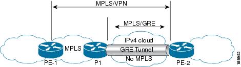
The following examples show how to configure Layer 3 VPN on the PE devices (PE1 and PE2) and MPLS segment (P1), and the GRE
tunnel from PE1 to P1 to PE2 (see P-to-PE Tunneling).
The following example shows how to configure loopback interface for GRE tunnel for PE1:
Device> enable
Device# configure terminal
Device(config)# interface Loopback4
Device(config-if)# ip address 209.165.200.230 255.255.255.255
Device(config-if)# end
The following example shows how to configure loopback interface for GRE tunnel for P1:
Device> enable
Device# configure terminal
Device(config)# interface Loopback100
Device(config-if)# ip address 209.165.200.235 255.255.255.255
Device(config-if)# end
The following example shows how to configure interface from PE1-P1 and configure IGP:
Device> enable
Device# configure terminal
Device(config)# interface Port-channel11
Device(config-if)# no switchport
Device(config-if)# ip address 209.165.201.1 255.255.255.248
Device(config-if)# ip ospf 10 area 0
Device(config-if)# end
The following example shows how to configure interface from P1-PE1 and configure IGP:
Device> enable
Device# configure terminal
Device(config)# interface Port-channel1
Device(config-if)# no switchport
Device(config-if)# ip address 209.165.201.2 255.255.255.248
Device(config-if)# ip broadcast-address 209.165.201.31
Device(config-if)# ip ospf 10 area 0
Device(config-if)# end
The following example shows how to advertise loopback in IGP on PE1:
Device> enable
Device# configure terminal
Device(config)# router ospf 10
Device(config-router)# router-id 198.51.100.10
Device(config-router)# network 209.165.200.230 0.0.0.0 area 0
Device(config-router)# end
The following example shows how to advertise loopback in IGP on P1:
Device> enable
Device# configure terminal
Device(config)# router ospf 10
Device(config-router)# router-id 198.51.100.20
Device(config-router)# network 209.165.200.235 0.0.0.0 area 0
Device(config-router)# end
The following example shows how to configure GRE tunnel, configure an IGP instance on the tunnel, and enable MPLS on the tunnel
on PE1:
Device> enable
Device# configure terminal
Device(config)# interface Tunnel111
Device(config-if)# ip address 209.165.202.140 255.255.255.248
Device(config-if)# ip ospf 11 area 0
Device(config-if)# mpls ip
Device(config-if)# tunnel source 209.165.200.230
Device(config-if)# tunnel destination 209.165.200.235
Device(config-if)# end
The following example shows how to configure GRE tunnel, configure an IGP instance on the tunnel, and enable MPLS on the tunnel
on P1:
Device> enable
Device# configure terminal
Device(config)# interface Tunnel111
Device(config-if)# ip address 209.165.202.141 255.255.255.248
Device(config-if)# ip ospf 11 area 0
Device(config-if)# mpls ip
Device(config-if)# tunnel source 209.165.200.235
Device(config-if)# tunnel destination 209.165.200.230
Device(config-if)# end
The following example shows how to advertise PE loopback IP for BGP in tunnel’s IGP instance on PE1:
Device> enable
Device# configure terminal
Device(config)# interface Tunnel111
Device(config)# router ospf 11
Device(config-router)# router-id 198.51.100.11
Device(config-router)# network 192.0.1.1 0.0.0.0 area 0
Device(config-router)# end
The following example shows how to configure interface from PE2-P1, and configure IGP and MPLS:
Device> enable
Device# configure terminal
Device(config)# interface Port-channel12
Device(config-if)# no switchport
Device(config-if)# ip address 209.165.201.1 255.255.255.248
Device(config-if)# ip ospf 11 area 0
Device(config-if)# mpls ip
Device(config-if)# end
The following example shows how to configure interface from P1-PE2, and configure IGP:
Device> enable
Device# configure terminal
Device(config)# interface Port-channel12
Device(config-if)# no switchport
Device(config-if)# ip address 209.165.201.2 255.255.255.248
Device(config-if)# ip ospf 11 area 0
Device(config-if)# mpls ip
Device(config-if)# end
The following example shows how to create VRF on PE1 where CE1 is connected:
Device> enable
Device# configure terminal
Device(config)# vrf definition vrf-1
Device (config-vrf)# rd 1:1
Device (config-vrf)# address-family ipv4
Device (config-vrf-af)# route-target import 1:2
Device (config-vrf-af)# route-target export 1:1
Device (config-vrf-af)# exit
Device (config-vrf)# end
The following example shows how to create VRF on PE2 where CE2 is connected:
Device> enable
Device# configure terminal
Device (config)# vrf definition vrf-1
Device (config-vrf)# rd 2:2
Device (config-vrf)# address-family ipv4
Device (config-vrf-af)# route-target import 1:1
Device (config-vrf-af)# route-target export 1:2
Device (config-vrf-af)# exit
Device (config-vrf)# end
The following example shows how to configure PE1-CE1 interface:
Device> enable
Device# configure terminal
Device (config)# int po14.1
Device (config-subif)# encapsulation dot1Q 10
Device (config-subif)# vrf forwarding vrf-1
Device (config-subif)# ip address 14.2.1.1 255.255.255.0
Device (config-subif)# exit
Device (config)# end
The following example shows how to configure PE2-CE2 interface:
Device> enable
Device# configure terminal
Device (config)# int po24.1
Device (config-subif)# encapsulation dot1Q 10
Device (config-subif)# vrf forwarding vrf-1
Device (config-subif)# ip address 24.2.1.1 255.255.255.0
Device (config-subif)# exit
Device (config)# end
The following example shows how to configure PE1-CE1 EBGP:
Device> enable
Device# configure terminal
Device (config)# router bgp 65040
Device (config-router)# address-family ipv4 vrf vrf-1
Device (config-router-af)# neighbor 14.2.1.2 remote-as 65041
Device (config-router-af)# neighbor 14.2.1.2 activate
Device (config-router-af)# exit-address-family
Device (config-router)# end
The following example shows how to configure PE2-CE2 EBGP:
Device> enable
Device# configure terminal
Device (config)# router bgp 65040
Device (config-router)# address-family ipv4 vrf vrf-1
Device (config-router-af)# neighbor 24.2.1.2 remote-as 65041
Device (config-router-af)# neighbor 24.2.1.2 activate
Device (config-router-af)# exit-address-family
Device (config-router)# end
The following example shows how to configure PE1-PE2 MP-BGP on PE1:
Device> enable
Device# configure terminal
Device (config)# router bgp 65040
Device (config-router)# neighbor 192.0.2.1 remote-as 65040
Device (config-router)# neighbor 192.0.2.1 update-source Loopback0
Device (config-router)# address-family ipv4
Device (config-router-af)# neighbor 192.0.2.1 activate
Device (config-router-af)# exit
Device (config-router)# address-family vpnv4
Device (config-router-af)#  neighbor 192.0.2.1 activate
Device (config-router-af)#  neighbor 192.0.2.1 send-community both
Device (config-router-af)# exit
Device (config-router)# end
The following example shows how to configure PE2-PE1 MP-BGP on PE2:
Device> enable
Device# configure terminal
Device (config)# router bgp 65040
Device (config-router)# neighbor 192.0.1.1 remote-as 65040
Device (config-router)# neighbor 192.0.1.1 update-source Loopback0
Device (config-router)# address-family ipv4
Device (config-router-af)# neighbor 192.0.1.1 activate
Device (config-router-af)# exit
Device (config-router)# address-family vpnv4
Device (config-router-af)# neighbor 192.0.1.1 activate
Device (config-router-af)# neighbor 192.0.1.1 send-community both
Device (config-router-af)# exit
Device (config-router)# end

 Feedback