- Index
- Preface
- Product Overview
- Command-Line Interfaces
- Initial Switch Configuration
- Supervisor Engine 720 Configuration
- Supervisor Engine 32 Configuration
- Supervisor Engine 2 and Switch Fabric Module Configuration
- NSF with SSO Supervisor Engine Redundancy
- RPR and RPR+ Supervisor Engine Redundancy
- Interface Configuration
- Layer 2 Ethernet Interface Configuration
- Flex Links
- Layer 3 and Layer 2 EtherChannel
- VLAN Trunking Protocol (VTP)
- VLANs
- Private VLANs (PVLANs)
- Cisco IP Phone Support
- IEEE 802.1Q Tunneling
- Layer 2 Protocol Tunneling (L2PT)
- Standard-Compliant IEEE MST
- STP and IEEE 802.1s MST
- STP Features
- Layer 3 Interface Configuration
- UDE and UDLR
- Multiprotocol Label Switching (MPLS)
- IPv4 Multicast VPN Support
- IP Unicast Layer 3 Switching
- IPv6 Multicast Layer 3 Switching
- IPv4 Multicast Layer 3 Switching
- IGMP Snooping
- PIM Snooping
- MLDv2 Snooping
- Router-Port Group Management Protocol (RGMP)
- Network Security
- Understanding Cisco IOS ACL Support
- VLAN ACLs (VACLs)
- Denial of Service (DoS) Protection
- DHCP Snooping
- Dynamic ARP Inspection (DAI)
- Traffic-Storm Control
- Unknown Unicast and Multicast Flood Blocking
- PFC QoS
- MPLS QoS
- PFC QoS Statistics Data Export
- Cisco IOS Firewall Feature Set
- Network Admission Control (NAC)
- IEEE 802.1X Port-Based Authentication
- Port Security
- Cisco Discovery Protocol (CDP)
- UniDirectional Link Detection (UDLD)
- NetFlow Table Configuration
- NetFlow Data Export (NDE)
- Local SPAN, Remote SPAN (RSPAN), and Encapsulated RSPAN
- SNMP IfIndex Persistence
- Power Management and Environmental Monitoring
- Online Diagnostic Configuration
- Top N Utility Reports
- Using the Layer 2 Traceroute Utility
- Online Diagnostic Tests
- Acronyms
Catalyst 6500 Release 12.2SXF and Rebuilds Software Configuration Guide
Bias-Free Language
The documentation set for this product strives to use bias-free language. For the purposes of this documentation set, bias-free is defined as language that does not imply discrimination based on age, disability, gender, racial identity, ethnic identity, sexual orientation, socioeconomic status, and intersectionality. Exceptions may be present in the documentation due to language that is hardcoded in the user interfaces of the product software, language used based on RFP documentation, or language that is used by a referenced third-party product. Learn more about how Cisco is using Inclusive Language.
- Updated:
- March 21, 2015
Chapter: IP Unicast Layer 3 Switching
Configuring IP Unicast Layer 3 Switching
This chapter describes how to configure IP unicast Layer 3 switching on the Catalyst 6500 series switches.

Note ![]() For complete syntax and usage information for the commands used in this chapter, refer to these publications:
For complete syntax and usage information for the commands used in this chapter, refer to these publications:
•![]() The Cisco IOS Master Command List, Release 12.2SX at this URL:
The Cisco IOS Master Command List, Release 12.2SX at this URL:
http://www.cisco.com/en/US/docs/ios/mcl/allreleasemcl/all_book.html
•![]() The Release 12.2 publications at this URL:
The Release 12.2 publications at this URL:
•![]() IPX traffic is fast switched on the MSFC. For more information, refer to this URL:
IPX traffic is fast switched on the MSFC. For more information, refer to this URL:
http://www.cisco.com/en/US/docs/ios/12_2/atipx/configuration/guide/fatipx_c.html
•![]() For information about IP multicast Layer 3 switching, see Chapter 28 "Configuring IPv4 Multicast Layer 3 Switching."
For information about IP multicast Layer 3 switching, see Chapter 28 "Configuring IPv4 Multicast Layer 3 Switching."
This chapter consists of these sections:
•![]() Understanding How Layer 3 Switching Works
Understanding How Layer 3 Switching Works
•![]() Default Hardware Layer 3 Switching Configuration
Default Hardware Layer 3 Switching Configuration
•![]() Configuration Guidelines and Restrictions
Configuration Guidelines and Restrictions
•![]() Configuring Hardware Layer 3 Switching
Configuring Hardware Layer 3 Switching
•![]() Displaying Hardware Layer 3 Switching Statistics
Displaying Hardware Layer 3 Switching Statistics

Tip ![]() For additional information about Cisco Catalyst 6500 Series Switches (including configuration examples and troubleshooting information), see the documents listed on this page:
For additional information about Cisco Catalyst 6500 Series Switches (including configuration examples and troubleshooting information), see the documents listed on this page:
http://www.cisco.com/en/US/products/hw/switches/ps708/tsd_products_support_series_home.html
Participate in the Technical Documentation Ideas forum
Understanding How Layer 3 Switching Works
These sections describe Layer 3 switching:
•![]() Understanding Hardware Layer 3 Switching
Understanding Hardware Layer 3 Switching
•![]() Understanding Layer 3-Switched Packet Rewrite
Understanding Layer 3-Switched Packet Rewrite
Understanding Hardware Layer 3 Switching
Hardware Layer 3 switching allows the PFC and DFCs, instead of the MSFC, to forward IP unicast traffic between subnets. Hardware Layer 3 switching provides wire-speed forwarding on the PFC and DFCs, instead of in software on the MSFC. Hardware Layer 3 switching requires minimal support from the MSFC. The MSFC routes any traffic that cannot be hardware Layer 3 switched.
Hardware Layer 3 switching supports the routing protocols configured on the MSFC. Hardware Layer 3 switching does not replace the routing protocols configured on the MSFC.
Hardware Layer 3 switching runs equally on the PF3 and DFCs to provide IP unicast Layer 3 switching locally on each module. Hardware Layer 3 switching provides the following functions:
•![]() Hardware access control list (ACL) switching for policy-based routing (PBR)
Hardware access control list (ACL) switching for policy-based routing (PBR)
•![]() Hardware NetFlow switching for TCP intercept, reflexive ACL forwarding decisions
Hardware NetFlow switching for TCP intercept, reflexive ACL forwarding decisions
•![]() Hardware Cisco Express Forwarding (CEF) switching for all other IP unicast traffic
Hardware Cisco Express Forwarding (CEF) switching for all other IP unicast traffic
Hardware Layer 3 switching on the PFC supports modules that do not have a DFC. The MSFC forwards traffic that cannot be Layer 3 switched.
Traffic is hardware Layer 3 switched after being processed by access lists and quality of service (QoS).
Hardware Layer 3 switching makes a forwarding decision locally on the ingress-port module for each packet and sends the rewrite information for each packet to the egress port, where the rewrite occurs when the packet is transmitted from the Catalyst 6500 series switch.
Hardware Layer 3 switching generates flow statistics for Layer 3-switched traffic. Hardware Layer 3 flow statistics can be used for NetFlow Data Export (NDE). (See Chapter 51 "Configuring NDE".)
Understanding Layer 3-Switched Packet Rewrite
When a packet is Layer 3 switched from a source in one subnet to a destination in another subnet, the Catalyst 6500 series switch performs a packet rewrite at the egress port based on information learned from the MSFC so that the packets appear to have been routed by the MSFC.
Packet rewrite alters five fields:
•![]() Layer 2 (MAC) destination address
Layer 2 (MAC) destination address
•![]() Layer 2 (MAC) source address
Layer 2 (MAC) source address
•![]() Layer 3 IP Time to Live (TTL)
Layer 3 IP Time to Live (TTL)
•![]() Layer 3 checksum
Layer 3 checksum
•![]() Layer 2 (MAC) checksum (also called the frame checksum or FCS)
Layer 2 (MAC) checksum (also called the frame checksum or FCS)
Note ![]() Packets are rewritten with the encapsulation appropriate for the next-hop subnet.
Packets are rewritten with the encapsulation appropriate for the next-hop subnet.
If Source A and Destination B are in different subnets and Source A sends a packet to the MSFC to be routed to Destination B, the switch recognizes that the packet was sent to the Layer 2 (MAC) address of the MSFC.
To perform Layer 3 switching, the switch rewrites the Layer 2 frame header, changing the Layer 2 destination address to the Layer 2 address of Destination B and the Layer 2 source address to the Layer 2 address of the MSFC. The Layer 3 addresses remain the same.
In IP unicast and IP multicast traffic, the switch decrements the Layer 3 TTL value by 1 and recomputes the Layer 3 packet checksum. The switch recomputes the Layer 2 frame checksum and forwards (or, for multicast packets, replicates as necessary) the rewritten packet to Destination B's subnet.
A received IP unicast packet is formatted (conceptually) as follows:
|
|
|
|
|
||||
|---|---|---|---|---|---|---|---|
Destination |
Source |
Destination |
Source |
TTL |
Checksum |
||
MSFC MAC |
Source A MAC |
Destination B IP |
Source A IP |
n |
calculation1 |
||
After the switch rewrites an IP unicast packet, it is formatted (conceptually) as follows:
|
|
|
|
|
||||
|---|---|---|---|---|---|---|---|
Destination |
Source |
Destination |
Source |
TTL |
Checksum |
||
Destination B MAC |
MSFC MAC |
Destination B IP |
Source A IP |
n-1 |
calculation2 |
||
Hardware Layer 3 Switching Examples
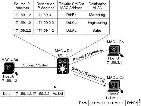
Figure 26-1 shows a simple network topology. In this example, Host A is on the Sales VLAN (IP subnet 171.59.1.0), Host B is on the Marketing VLAN (IP subnet 171.59.3.0), and Host C is on the Engineering VLAN (IP subnet 171.59.2.0).
When Host A initiates an HTTP file transfer to Host C, Hardware Layer 3 switching uses the information in the local forwarding information base (FIB) and adjacency table to forward packets from Host A to Host C.
Figure 26-1 Hardware Layer 3 Switching Example Topology
Default Hardware Layer 3 Switching Configuration
Table 26-1 shows the default hardware Layer 3 switching configuration.
|
|
|
|---|---|
Hardware Layer 3 switching enable state |
Enabled (cannot be disabled) |
Cisco IOS CEF enable state on MSFC |
Enabled (cannot be disabled) |
Cisco IOS dCEF1 enable state on MSFC |
Enabled (cannot be disabled) |
1 dCEF = Distributed Cisco Express Forwarding |
Configuration Guidelines and Restrictions
Follow these guidelines and restrictions when configuring hardware Layer 3 switching:
•![]() Hardware Layer 3 switching supports the following ingress and egress encapsulations:
Hardware Layer 3 switching supports the following ingress and egress encapsulations:
–![]() Ethernet V2.0 (ARPA)
Ethernet V2.0 (ARPA)
–![]() 802.3 with 802.2 with 1 byte control (SAP1)
802.3 with 802.2 with 1 byte control (SAP1)
Configuring Hardware Layer 3 Switching
Note ![]() For information on configuring unicast routing on the MSFC, see Chapter 22 "Configuring Layer 3 Interfaces."
For information on configuring unicast routing on the MSFC, see Chapter 22 "Configuring Layer 3 Interfaces."
Hardware Layer 3 switching is permanently enabled. No configuration is required.
To display information about Layer 3-switched traffic, perform this task:
|
|
|
|---|---|
Router# show interface {{type1 slot/port} | {port-channel number}} | begin L3 |
Displays a summary of Layer 3-switched traffic. |
1 type = ethernet, fastethernet, gigabitethernet, or tengigabitethernet |
This example shows how to display information about hardware Layer 3-switched traffic on Fast Ethernet port 3/3:
Router# show interface fastethernet 3/3 | begin L3
L3 in Switched: ucast: 0 pkt, 0 bytes - mcast: 12 pkt, 778 bytes mcast
L3 out Switched: ucast: 0 pkt, 0 bytes - mcast: 0 pkt, 0 bytes
4046399 packets input, 349370039 bytes, 0 no buffer
Received 3795255 broadcasts, 2 runts, 0 giants, 0 throttles
<...output truncated...>
Router#
Note ![]() The Layer 3 switching packet count is updated approximately every five seconds.
The Layer 3 switching packet count is updated approximately every five seconds.
Cisco IOS CEF and dCEF are permanently enabled. No configuration is required to support hardware Layer 3 switching.
With a PFC (and DFCs, if present), hardware Layer 3 switching uses per-flow load balancing based on IP source and destination addresses. Per-flow load balancing avoids the packet reordering that can be necessary with per-packet load balancing. For any given flow, all PFC- and DFC-equipped switches make exactly the same load-balancing decision, which can result in nonrandom load balancing.
The Cisco IOS CEF ip load-sharing per-packet, ip cef accounting per-prefix, and ip cef accounting non-recursive commands on the MSFC apply only to traffic that is CEF-switched in software on the MSFC. The commands do not affect traffic that is hardware Layer 3 switched on the PFC or on DFC-equipped switching modules.
For information about Cisco IOS CEF and dCEF on the MSFC, refer to these publications:
•![]() The "Cisco Express Forwarding" sections at this URL:
The "Cisco Express Forwarding" sections at this URL:
http://www.cisco.com/en/US/docs/ios/12_2/switch/configuration/guide/xcfcef.html
•![]() The Cisco IOS Switching Services Command Reference publication at this URL:
The Cisco IOS Switching Services Command Reference publication at this URL:
http://www.cisco.com/en/US/docs/ios/12_2/switch/command/reference/fswtch_r.html
Displaying Hardware Layer 3 Switching Statistics
Hardware Layer 3 switching statistics are obtained on a per-VLAN basis.
To display hardware Layer 3 switching statistics, perform this task:
|
|
|
|---|---|
Router# show interfaces {{type1 slot/port} | {port-channel number}} |
Displays hardware Layer 3 switching statistics. |
1 type = ethernet, fastethernet, gigabitethernet, or tengigabitethernet |
This example shows how to display hardware Layer 3 switching statistics:
Router# show interfaces gigabitethernet 9/5 | include Switched
L2 Switched: ucast: 8199 pkt, 1362060 bytes - mcast: 6980 pkt, 371952 bytes
L3 in Switched: ucast: 0 pkt, 0 bytes - mcast: 0 pkt, 0 bytes mcast
L3 out Switched: ucast: 0 pkt, 0 bytes - mcast: 0 pkt, 0 bytes
To display adjacency table information, perform this task:
|
|
|
|---|---|
Router# show adjacency [{{type1 slot/port} | {port-channel number}} | detail | internal | summary] |
Displays adjacency table information. The optional detail keyword displays detailed adjacency information, including Layer 2 information. |
1 type = ethernet, fastethernet, gigabitethernet, or tengigabitethernet |
This example shows how to display adjacency statistics:
Router# show adjacency gigabitethernet 9/5 detail
Protocol Interface Address
IP GigabitEthernet9/5 172.20.53.206(11)
504 packets, 6110 bytes
00605C865B82
000164F83FA50800
ARP 03:49:31
Note ![]() Adjacency statistics are updated approximately every 60 seconds.
Adjacency statistics are updated approximately every 60 seconds.
Tip ![]() For additional information about Cisco Catalyst 6500 Series Switches (including configuration examples and troubleshooting information), see the documents listed on this page:
For additional information about Cisco Catalyst 6500 Series Switches (including configuration examples and troubleshooting information), see the documents listed on this page:
http://www.cisco.com/en/US/products/hw/switches/ps708/tsd_products_support_series_home.html
Participate in the Technical Documentation Ideas forum
 Feedback