- interface
- interface (virtual switch)
- interface port-channel
- interface range
- interface vlan
- ip admission proxy http refresh-all
- ip arp inspection filter vlan
- ip arp inspection limit (interface)
- ip arp inspection log-buffer
- ip arp inspection trust
- ip arp inspection validate
- ip arp inspection vlan
- ip arp inspection vlan logging
- ip cef load-sharing algorithm
- ip device tracking maximum
- ip device tracking probe
- ip dhcp snooping
- ip dhcp snooping binding
- ip dhcp snooping database
- ip dhcp snooping information option
- ip dhcp snooping information option allow-untrusted
- ip dhcp snooping limit rate
- ip dhcp snooping trust
- ip dhcp snooping vlan
- ip dhcp snooping vlan information option format-type circuit-id string
- ip igmp filter
- ip igmp max-groups
- ip igmp profile
- ip igmp query-interval
- ip igmp snooping
- ip igmp snooping report-suppression
- ip igmp snooping vlan
- ip igmp snooping vlan explicit-tracking
- ip igmp snooping vlan immediate-leave
- ip igmp snooping vlan mrouter
- ip igmp snooping vlan static
- ip local-proxy-arp
- ip mfib fastdrop
- ip multicast multipath
- ip name-server
- ip route-cache flow
- ip source binding
- ip ssh source-interface
- ip sticky-arp
- ip verify header vlan all
- ip verify source
- ip verify unicast source reachable-via
- ip wccp
- ipv6 wccp
- ip wccp check services all
- ip wccp group-listen
- ip wccp redirect
- ip wccp redirect exclude in
- ipv6 dhcp-lrda
- ipv6 dhcp-ldra interface-id
- ipv6 dhcp-ldra attach-policy
- ipv6 dhcp lrda attach-policy (VLAN)
- ipv6 dhcp relay destination
- ipv6 mld snooping
- ipv6 mld snooping last-listener-query-count
- ipv6 mld snooping last-listener-query-interval
- ipv6 mld snooping listener-message-suppression
- ipv6 mld snooping robustness-variable
- ipv6 mld snooping tcn
- ipv6 mld snooping vlan
- issu abortversion
- issu acceptversion
- issu commitversion
- issu loadversion
- issu runversion
- issu set rollback-timer
- itr
- itr map-resolver
- key chain macsec
- l2protocol-tunnel
- l2protocol-tunnel cos
- l2protocol-tunnel drop-threshold
- l2protocol-tunnel shutdown-threshold
- lacp port-priority
- lacp system-priority
- license right-to-use activate
- license right-to-use deactivate
- link state group
- link state track
- lldp tlv-select power-management
- locator default-set
- locator-set
- logging event link-status global (global configuration)
- logging event link-status (interface configuration)
- logging event trunk-status global (global configuration)
- logging event trunk-status (interface configuration)
- mab
- mab logging verbose
- mac access-list extended
- mac-address (virtual switch)
- mac-address-table aging-time
- mac-address-table dynamic group protocols
- mac-address-table learning vlan
- mac-address-table notification
- mac-address-table static
- macro apply cisco-desktop
- macsec network-link
- map-cache
- mka
- mka policy
- macro apply cisco-phone
- macro apply cisco-router
- macro apply cisco-switch
- macro auto device
- macro auto execute (built-in function)
- macro auto execute (remotely-defined trigger)
- macro auto execute (user-defined function)
- macro auto global processing
- macro auto mac-address-group
- macro auto monitor
- macro auto processing
- macro auto sticky
- macro global apply cisco-global
- macro global apply system-cpp
- macro global description
- main-cpu
- match
- match (class-map configuration)
- match flow ip
- mdix auto
- media-type
- mode
- monitor capture {access-list | class-map}
- monitor capture [clear | export]
- monitor capture [interface | vlan | control-plane]
- monitor capture file location buffer-size
- monitor capture limit
- monitor capture mycap match
- monitor capture start
- monitor session
- mtu
- mvr (global configuration)
- mvr (interface configuration)
- name
- netflow-lite exporter
- netflow-lite monitor
- netflow-lite sampler
- nmsp
- nmsp attachment suppress
- object-group
- options timeout (netflow-lite exporter submode)
- packet-offset (netflow-lite sampler submode)
- packet-rate (netflow-lite sampler submode)
- packet-section size (netflow-lite sampler submode)
- pagp learn-method
- pagp port-priority
- passive-interface
- permit
- police
- police (percent)
- police rate
- police (two rates)
- policy-map
- port-channel auto
- port-channel load-balance
- port-channel standalone-disable
- port-security mac-address
- port-security mac-address sticky
- port-security maximum
- power dc input
- power efficient-ethernet auto
- power inline
- power inline consumption
- power inline four-pair forced
- power inline logging global
- power inline police
- power redundancy combined max inputs
- power redundancy-mode
- pppoe intermediate-agent (global)
- pppoe intermediate-agent (interface)
- pppoe intermediate-agent (interface vlan-range)
- pppoe intermediate-agent format-type (global)
- pppoe intermediate-agent format-type (interface)
- pppoe intermediate-agent format-type (interface vlan-range)
- pppoe intermediate-agent limit rate
- pppoe intermediate-agent trust
- pppoe intermediate-agent vendor-tag strip
- priority
- private-vlan
- private-vlan mapping
- private-vlan synchronize
- profile
- profile flow
- qos account layer-all encapsulation
- qos account layer2 encapsulation
- qos trust
- queue-limit
- redundancy
- redundancy config-sync mismatched-commands
- redundancy force-switchover
- redundancy reload
- remote login module
- remote-span
- renew ip dhcp snooping database
- rep admin vlan
- rep block port
- rep lsl-age-timer
- rep preempt delay
- rep preempt segment
- rep segment
- rep stcn
- reset
- revision
- sampler (netflow-lite monitor submode)
- service
- service-policy (interface configuration)
- service-policy (policy-map class)
- service-policy input (control-plane)
- session module
- set
- set cos
- set dscp
- set ip next-hop verify-availability
- set precedence
- set qos-group
- shape (class-based queueing)
- shape (interface configuration)
- shell trigger
- use-petr
interface
To select an interface to configure and to enter interface configuration mode, use the interface command.
Syntax Description
Type of interface to be configured; see Valid type Values for valid values. |
|
Command Default
Command Modes
Command History
|
|
|
|---|---|
The fortygigabitethernet option was introduced on on Cisco Catalyst 4500E Series Switches configured with Supervisor Engine 9-E. |
|
Usage Guidelines
Table 2-8 lists the valid values for type .
|
|
|
|---|---|
40-Gigabit Ethernet interface; supported on Cisco Catalyst 4500E Series Switches configured with Supervisor Engine 9-E. To use this interface type, first enable the corresponding uplink mode—enter the hw-module uplink mode 80Gig command in global configuration mode. In this mode, the 10-GE uplink ports on the supervisor are not available, but if there are other 10-GE linecards in the chassis, the tengigabitethernet option is available on the CLI. |
|
Gigabit Ethernet WAN IEEE 802.3z interface; supported on Catalyst 4500 series switch that are configured with a Supervisor Engine 2 only. |
|
Packet OC-3 interface on the Packet over SONET Interface Processor; supported on Catalyst 4500 series switch that are configured with a Supervisor Engine 2 only. |
|
ATM interface; supported on Catalyst 4500 series switch that are configured with a Supervisor Engine 2 only. |
|
VLAN interface; see the interface vlan command. |
|
Port channel interface; see the interface port-channel command. |
|
Examples
The following example shows how to enter the interface configuration mode on the Fast Ethernet interface 2/4:
Related Commands
|
|
|
|---|---|
interface (virtual switch)
To select an interface to configure and enter interface configuration mode, use the interface global configuration mode command.
interface [interface switch-num/slot/port.subinterface }
Syntax Description
Specifies the interface to be configured; see Valid type Values for valid values. |
|
Command Default
Command Modes
Command History
|
|
|
|---|---|
Usage Guidelines
Table 2-9 lists the valid values for type .
|
|
|
|---|---|
VLAN interface; see the interface vlan command. |
|
Port channel interface; see the interface port-channel command. |
|
Examples
The following example shows how to enter the interface configuration mode on the GigabitEthernet interface for switch 1, module 2, port 4:
Related Commands
|
|
|
|---|---|
interface port-channel
To access or create a port-channel interface, use the interface port-channel command.
interface port-channel channel-group
Syntax Description
Command Default
Command Modes
Command History
|
|
|
|---|---|
This command was introduced on the Catalyst 4500 series switch. |
Usage Guidelines
You do not have to create a port-channel interface before assigning a physical interface to a channel group. A port-channel interface is created automatically when the channel group gets its first physical interface, if it is not already created.
You can also create the port channels by entering the interface port-channel command. This will create a Layer 3 port channel. To change the Layer 3 port channel into a Layer 2 port channel, use the switchport command before you assign the physical interfaces to the channel group. A port channel cannot be changed from Layer 3 to Layer 2 or vice versa when it contains member ports.
Only one port channel in a channel group is allowed.

If you want to use CDP, you must configure it only on the physical Fast Ethernet interface and not on the port-channel interface.
Examples
This example creates a port-channel interface with a channel-group number of 64:
Related Commands
|
|
|
|---|---|
Assigns and configures an EtherChannel interface to an EtherChannel group. |
|
interface range
To run a command on multiple ports at the same time, use the interface range command.
interface range { vlan vlan_id - vlan_id } { port-range | macro name }
Syntax Description
Port range; for a list of valid values for port-range, see the “Usage Guidelines” section. |
|
Command Default
Command Modes
Command History
|
|
|
|---|---|
This command was introduced on the Catalyst 4500 series switch. |
|
Usage Guidelines
You can use the interface range command on the existing VLAN SVIs only. To display the VLAN SVIs, enter the show running config command. The VLANs that are not displayed cannot be used in the interface range command.
The values that are entered with the interface range command are applied to all the existing VLAN SVIs.
Before you can use a macro, you must define a range using the define interface-range command.
All configuration changes that are made to a port range are saved to NVRAM, but the port ranges that are created with the interface range command do not get saved to NVRAM.
You can enter the port range in two ways:
You can either specify the ports or the name of a port-range macro. A port range must consist of the same port type, and the ports within a range cannot span the modules.
You can define up to five port ranges on a single command; separate each range with a comma.
When you define a range, you must enter a space between the first port and the hyphen (-):
Use these formats when entering the port-range :
- interface-type { mod }/{ first-port } - { last-port }
- interface-type { mod }/{ first-port } - { last-port }
Valid values for interface-type are as follows:
Although the port-channel interface range is 1 to 256, in a VSS setup, there is a discrepancy in the way the range is displayed on the CLI when you enter the beginning of the interface range before you enter the ? prompt. This discrepancy is not seen on a standalone switch.
When you enter the beginning of the interface range, the CLI output is displayed as follows:
To continue, you have to enter the beginning of the next number range:
If you do not enter the beginning of the interface range, the CLI output is displayed as follows:
You cannot specify both a macro and an interface range in the same command. After creating a macro, you can enter additional ranges. If you have already entered an interface range, the CLI does not allow you to enter a macro.
You can specify a single interface in the port-range value. This makes the command similar to the interface interface-number command.
Examples
The following example shows how to use the interface range command to interface to FE 5/18 - 20:
This command shows how to run a port-range macro:
Related Commands
|
|
|
|---|---|
interface vlan
To create or access a Layer 3 switch virtual interface (SVI), use the interface vlan command. To delete an SVI, use the no form of this command.
Syntax Description
Command Default
Command Modes
Command History
|
|
|
|---|---|
This command was introduced on the Catalyst 4500 series switch. |
|
Usage Guidelines
The SVIs are created the first time that you enter the interface vlan vlan_id command for a particular VLAN. The vlan_id value corresponds to the VLAN tag that is associated with the data frames on an ISL or 802.1Q-encapsulated trunk or the VLAN ID that is configured for an access port. A message is displayed whenever a VLAN interface is newly created, so you can check that you entered the correct VLAN number.
If you delete an SVI by entering the no interface vlan vlan_id command, the associated interface is forced into an administrative down state and marked as deleted. The deleted interface will no longer be visible in a show interface command.
You can reinstate a deleted SVI by entering the interface vlan vlan_id command for the deleted interface. The interface comes back up, but much of the previous configuration will be gone.
Examples
The following example shows the output when you enter the interface vlan vlan_id command for a new VLAN number:
ip admission proxy http refresh-all
To ensure that you see a customized WebAuth login page with the same name in the switch system directory as a same-named prior login page, use the ip admission proxy http refresh-all command.
ip admission proxy http [success | failure | refresh-all | login [expired | page]]
Syntax Description
Command Default
If you do not enter this command, if any of the customized web-based authentication page files with the file of same name have been changed, you see the old login page rather than the new file.
Command Modes
Command History
|
|
|
|---|---|
This command was introduced on the Catalyst 4500 series switch. |
Usage Guidelines
You should enter this command whenever the customized web-based authentication page has been changed in the system directory.
Examples
The following example shows how to enter this command:
ip arp inspection filter vlan
To permit ARPs from hosts that are configured for static IP when DAI is enabled and to define an ARP access list and apply it to a VLAN, use the ip arp inspection filter vlan command. To disable this application, use the no form of this command.
ip arp inspection filter arp-acl-name vlan vlan-range [ static ]
no ip arp inspection filter arp-acl-name vlan vlan-range [ static ]
Syntax Description
(Optional) Specifies that the access control list should be applied statically. |
Command Default
Command Modes
Command History
|
|
|
|---|---|
This command was introduced on the Catalyst 4500 series switch. |
Usage Guidelines
When an ARP access control list is applied to a VLAN for dynamic ARP inspection, the ARP packets containing only the IP-to-Ethernet MAC bindings are compared against the ACLs. All other packet types are bridged in the incoming VLAN without validation.
This command specifies that the incoming ARP packets are compared against the ARP access control list, and the packets are permitted only if the access control list permits them.
If the access control lists deny the packets because of explicit denies, the packets are dropped. If the packets are denied because of an implicit deny, they are then matched against the list of DHCP bindings if the ACL is not applied statically.
Examples
The following example shows how to apply the ARP ACL static hosts to VLAN 1 for DAI:
Related Commands
|
|
|
|---|---|
Defines an ARP access list or adds clauses at the end of a predefined list. |
|
Displays the status of dynamic ARP inspection for a specific range of VLANs. |
ip arp inspection limit (interface)
To limit the rate of incoming ARP requests and responses on an interface and prevent DAI from consuming all of the system’s resources in the event of a DoS attack, use the ip arp inspection limit command. To release the limit, use the no form of this command.
ip arp inspection limit { rate pps | none } [ burst interval seconds ]
Syntax Description
Command Default
The rate is set to 15 packets per second on the untrusted interfaces, assuming that the network is a switched network with a host connecting to as many as 15 new hosts per second.
Command Modes
Command History
|
|
|
|---|---|
This command was introduced on the Catalyst 4500 series switch. |
|
Usage Guidelines
The trunk ports should be configured with higher rates to reflect their aggregation. When the rate of the incoming packets exceeds the user-configured rate, the interface is placed into an error-disabled state. The error-disable timeout feature can be used to remove the port from the error-disabled state. The rate applies to both the trusted and nontrusted interfaces. Configure appropriate rates on trunks to handle the packets across multiple DAI-enabled VLANs or use the none keyword to make the rate unlimited.
The rate of the incoming ARP packets onthe channel ports is equal to the sum of the incoming rate of packets from all the channel members. Configure the rate limit for the channel ports only after examining the rate of the incoming ARP packets on the channel members.
After a switch receives more than the configured rate of packets every second consecutively over a period of burst seconds, the interface is placed into an error-disabled state.
Examples
The following example shows how to limit the rate of the incoming ARP requests to 25 packets per second:
The following example shows how to limit the rate of the incoming ARP requests to 20 packets per second and to set the interface monitoring interval to 5 consecutive seconds:
Related Commands
|
|
|
|---|---|
Displays the status of dynamic ARP inspection for a specific range of VLANs. |
ip arp inspection log-buffer
To configure the parameters that are associated with the logging buffer, use the ip arp inspection log-buffer command. To disable the parameters, use the no form of this command.
ip arp inspection log-buffer { entries number | logs number interval seconds }
no ip arp inspection log-buffer { entries | logs }
Syntax Description
Command Default
When dynamic ARP inspection is enabled, denied, or dropped, the ARP packets are logged.
The number of entries is set to 32.
Command Modes
Command History
|
|
|
|---|---|
This command was introduced on the Catalyst 4500 series switch. |
Usage Guidelines
The first dropped packet of a given flow is logged immediately. The subsequent packets for the same flow are registered but are not logged immediately. Registering these packets is done in a log buffer that is shared by all the VLANs. Entries from this buffer are logged on a rate-controlled basis.
Examples
The following example shows how to configure the logging buffer to hold up to 45 entries:
The following example shows how to configure the logging rate to 10 logs per 3 seconds:
Related Commands
|
|
|
|---|---|
Defines an ARP access list or adds clauses at the end of a predefined list. |
|
Displays the status of dynamic ARP inspection for a specific range of VLANs. |
ip arp inspection trust
To set a per-port configurable trust state that determines the set of interfaces where incoming ARP packets are inspected, use the ip arp inspection trust command. To make the interfaces untrusted, use the no form of this command.
Syntax Description
Command Default
Command Modes
Command History
|
|
|
|---|---|
This command was introduced on the Catalyst 4500 series switch. |
Examples
The following example shows how to configure an interface to be trusted:
To verify the configuration, use the show form of this command:
Related Commands
|
|
|
|---|---|
Displays the status of dynamic ARP inspection for a specific range of VLANs. |
ip arp inspection validate
To perform specific checks for ARP inspection, use the ip arp inspection validate command. To disable checks, use the no form of this command.
ip arp inspection validate [ src-mac ] [ dst-mac ] [ ip ]
no ip arp inspection validate [ src-mac ] [ dst-mac ] [ ip ]
Syntax Description
Command Default
Command Modes
Command History
|
|
|
|---|---|
This command was introduced on the Catalyst 4500 series switch. |
Usage Guidelines
When enabling the checks, specify at least one of the keywords (src-mac, dst-mac, and ip) on the command line. Each command overrides the configuration of the previous command. If a command enables src and dst mac validations, and a second command enables IP validation only, the src and dst mac validations are disabled as a result of the second command.
The no form of this command disables only the specified checks. If none of the check options are enabled, all the checks are disabled.
Examples
This example show how to enable the source MAC validation:
Related Commands
|
|
|
|---|---|
Defines an ARP access list or adds clauses at the end of a predefined list. |
|
Displays the status of dynamic ARP inspection for a specific range of VLANs. |
ip arp inspection vlan
To enable dynamic ARP inspection (DAI) on a per-VLAN basis, use the ip arp inspection vlan command. To disable DAI, use the no form of this command.
ip arp inspection vlan vlan-range
no ip arp inspection vlan vlan-range
Syntax Description
Command Default
Command Modes
Command History
|
|
|
|---|---|
This command was introduced on the Catalyst 4500 series switch. |
Usage Guidelines
You must specify on which VLANs to enable DAI. DAI may not function on the configured VLANs if they have not been created or if they are private.
Examples
The following example shows how to enable DAI on VLAN 1:
The following example shows how to disable DAI on VLAN 1:
Related Commands
|
|
|
|---|---|
Defines an ARP access list or adds clauses at the end of a predefined list. |
|
Displays the status of dynamic ARP inspection for a specific range of VLANs. |
ip arp inspection vlan logging
To control the type of packets that are logged, use the ip arp inspection vlan logging command. To disable this logging control, use the no form of this command.
ip arp inspection vlan vlan-range logging { acl-match { matchlog | none } | dhcp-bindings { permit | all | none }}
no ip arp inspection vlan vlan-range logging { acl-match | dhcp-bindings }
Syntax Description
Command Default
Command Modes
Command History
|
|
|
|---|---|
This command was introduced on the Catalyst 4500 series switch. |
Usage Guidelines
The acl-match and dhcp-bindings keywords merge with each other. When you set an ACL match configuration, the DHCP bindings configuration is not disabled. You can use the no form of this command to reset some of the logging criteria to their defaults. If you do not specify either option, all the logging types are reset to log on when the ARP packets are denied. The two options that are available to you are as follows:
Examples
The following example shows how to configure an ARP inspection on VLAN 1 to add packets to a log on matching against the ACLs with the logging keyword:
Related Commands
|
|
|
|---|---|
Defines an ARP access list or adds clauses at the end of a predefined list. |
|
Displays the status of dynamic ARP inspection for a specific range of VLANs. |
ip cef load-sharing algorithm
To configure the load-sharing hash function so that the source TCP/UDP port, the destination TCP/UDP port, or both ports can be included in the hash in addition to the source and destination IP addresses, use the ip cef load-sharing algorithm command. To revert back to the default, which does not include the ports, use the no form of this command.
ip cef load-sharing algorithm { include-ports { source source | destination dest } | original | tunnel | universal }
no ip cef load-sharing algorithm { include-ports { source source | destination dest } | original | tunnel | universal }
Syntax Description
Command Default
Default load-sharing algorithm is disabled.

Note![]() This option does not include the source or destination port in the load-balancing hash.
This option does not include the source or destination port in the load-balancing hash.
Command Modes
Command History
|
|
|
|---|---|
This command was introduced on the Catalyst 4500 series switch. |
Usage Guidelines
The original algorithm, tunnel algorithm, and universal algorithm are routed through the hardware. For software-routed packets, the algorithms are handled by the software. The include-ports option does not apply to the software-switched traffic.
Examples
The following example shows how to configure the IP CEF load-sharing algorithm that includes Layer 4 ports:
The following example shows how to configure the IP CEF load-sharing algorithm that includes Layer 4 tunneling ports:
Related Commands
|
|
|
|---|---|
Displays the IP CEF VLAN interface status and configuration information. |
ip device tracking maximum
To enable IP port security binding tracking on a Layer 2 port, use the ip device tracking maximum command. To disable IP port security on untrusted Layer 2 interfaces, use the no form of this command.
ip device tracking maximum { number }
no ip device tracking maximum { number }
Syntax Description
Specifies the number of bindings created in the IP device tracking table for a port, valid values are from 0 to 65535. |
Command Default
Command Modes
Command History
|
|
|
|---|---|
This command was introduced on the Catalyst 4500 series switch. |
|
The upper limit for the number of bindings you can specifiy was increased from 2048 to 65535. |
Examples
The following example shows how to enable IP port security with IP-MAC filters on a Layer 2 access port:
You can verify your settings by entering the show ip verify source privileged EXEC command.
Related Commands
|
|
|
|---|---|
Displays the IP source guard configuration and filters on a particular interface. |
ip device tracking probe
To enable the tracking of device probes, use the ip device tracking probe command in configuration mode. To disable device probes, use the no form of this command.
ip device tracking probe { count count | delay interval | interval interval }
no ip device tracking probe { count count | delay interval | interval interval }
Note![]() Starting with Cisco IOS XE Release 3.10.1E, the [no] ip device tracking probe count and [no] ip device tracking probe delay commands are deprecated; there are no replacement commands.
Starting with Cisco IOS XE Release 3.10.1E, the [no] ip device tracking probe count and [no] ip device tracking probe delay commands are deprecated; there are no replacement commands.
Syntax Description
Command Default
Command Modes
Command History
|
|
|
|---|---|
This command was introduced on the Catalyst 4500 series switch. |
|
Examples
The following example shows how to set the interval time to 35:
Related Commands
|
|
|
|---|---|
ip dhcp snooping
To enable DHCP snooping globally, use the ip dhcp snooping command. To disable DHCP snooping, use the no form of this command.
Syntax Description
Command Default
Command Modes
Command History
|
|
|
|---|---|
This command was introduced on the Catalyst 4500 series switch. |
Usage Guidelines
You must enable DHCP snooping globally before you can use DHCP snooping on a VLAN.
Examples
The following example shows how to enable DHCP snooping:
The following example shows how to disable DHCP snooping:
Related Commands
|
|
|
|---|---|
Configures the number of the DHCP messages that an interface can receive per second. |
|
ip dhcp snooping binding
To set up and generate a DHCP binding configuration to restore bindings across reboots, use the ip dhcp snooping binding command. To disable the binding configuration, use the no form of this command.
ip dhcp snooping binding mac-address vlan vlan-# ip-address interface interface expiry seconds
no ip dhcp snooping binding mac-address vlan vlan-# ip-address interface interface
Syntax Description
Specifies the interval (in seconds) after which binding is no longer valid. |
Command Default
Command Modes
Command History
|
|
|
|---|---|
This command was introduced on the Catalyst 4500 series switch. |
|
Support for the 10-Gigabit Ethernet interface was introduced on the Catalyst 4500 series switch. |
Usage Guidelines
Whenever a binding is added or removed using this command, the binding database is marked as changed and a write is initiated.
Examples
The following example shows how to generate a DHCP binding configuration on interface gigabitethernet1/1 in VLAN 1 with an expiration time of 1000 seconds:
Related Commands
|
|
|
|---|---|
ip dhcp snooping database
To store the bindings that are generated by DHCP snooping, use the ip dhcp snooping database command. To either reset the timeout, reset the write-delay, or delete the agent specified by the URL, use the no form of this command.
ip dhcp snooping database { url | timeout seconds | write-delay seconds }
no ip dhcp snooping database {timeout | write-delay}
Syntax Description
Command Default
Command Modes
Command History
|
|
|
|---|---|
This command was introduced on the Catalyst 4500 series switch. |
Usage Guidelines
You need to create an empty file at the configured URL on network-based URLs (such as TFTP and FTP) before the switch can write the set of bindings for the first time at the URL.
Note![]() Because both NVRAM and bootflash have limited storage capacity, using TFTP or network-based files is recommended. If you use flash to store the database file, new updates (by the agent) result in the creation of new files (flash fills quickly). In addition, due to the nature of the file system used on the flash, a large number of files causes access to be considerably slowed. When a file is stored in a remote location accessible through TFTP, an RPR/SSO standby supervisor engine can take over the binding list when a switchover occurs.
Because both NVRAM and bootflash have limited storage capacity, using TFTP or network-based files is recommended. If you use flash to store the database file, new updates (by the agent) result in the creation of new files (flash fills quickly). In addition, due to the nature of the file system used on the flash, a large number of files causes access to be considerably slowed. When a file is stored in a remote location accessible through TFTP, an RPR/SSO standby supervisor engine can take over the binding list when a switchover occurs.
Examples
The following example shows how to store a database file with the IP address 10.1.1.1 within a directory called directory. A file named file must be present on the TFTP server.
Related Commands
|
|
|
|---|---|
Sets up and generates a DHCP binding configuration to restore bindings across reboots. |
|
ip dhcp snooping information option
To enable DHCP option 82 data insertion, use the ip dhcp snooping information option command. To disable DHCP option 82 data insertion, use the no form of this command.
ip dhcp snooping information option format remote-id { hostname | string { word }}
no ip dhcp snooping information option format remote-id { hostname | string { word }}
Syntax Description
Specifies the user-defined string for the remote ID. The word string can be from 1 to 63 characters long with no spaces. |
Command Default
Command Modes
Command History
|
|
|
|---|---|
This command was introduced on the Catalyst 4500 series switch. |
|
Usage Guidelines
If the hostname is longer than 63 characters it is truncated to 63 characters in the remote ID.
Examples
The following example shows how to enable DHCP option 82 data insertion:
The following example shows how to disable DHCP option 82 data insertion:
The following example shows how to configure the hostname as the remote ID:
The following example shows how to enable DHCP Snooping on VLAN 500 through 555 and option 82 remote ID:
Related Commands
|
|
|
|---|---|
Sets up and generates a DHCP binding configuration to restore bindings across reboots. |
|
Configures the number of the DHCP messages that an interface can receive per second. |
|
ip dhcp snooping vlan information option format-type circuit-id string |
Enables circuit-id (a sub-option of DHCP snooping option-82) on a VLAN. |
ip dhcp snooping information option allow-untrusted
To allow DHCP packets with option 82 data inserted to be received from a snooping untrusted port, use the ip dhcp snooping information option allow-untrusted command. To disallow receipt of these DHCP packets, use the no form of this command.
ip dhcp snooping information option allow-untrusted
no ip dhcp snooping information option allow-untrusted
Syntax Description
Command Default
DHCP packets with option 82 are not allowed on snooping untrusted ports.
Command Modes
Command History
|
|
|
|---|---|
This command was introduced on the Catalyst 4500 series switch. |
Examples
The following example shows how to allow DHCP packets with option 82 data inserted to be received from a snooping untrusted port:
Switch(config)# end
Related Commands
|
|
|
|---|---|
Configures the number of the DHCP messages that an interface can receive per second. |
|
ip dhcp snooping limit rate
To configure the number of the DHCP messages that an interface can receive per second, use the ip dhcp snooping limit rate command. To disable the DHCP snooping rate limiting, use the no form of this command.
ip dhcp snooping limit rate rate
no ip dhcp snooping limit rate
Syntax Description
Command Default
Command Modes
Command History
|
|
|
|---|---|
This command was introduced on the Catalyst 4500 series switch. |
Usage Guidelines
Typically, the rate limit applies to the untrusted interfaces. If you want to set up rate limiting for the trusted interfaces, note that the trusted interfaces aggregate all DHCP traffic in the switch, and you will need to adjust the rate limit of the interfaces to a higher value.
Examples
The following example shows how to enable the DHCP message rate limiting:
The following example shows how to disable the DHCP message rate limiting:
Related Commands
|
|
|
|---|---|
ip dhcp snooping trust
To configure an interface as trusted for DHCP snooping purposes, use the ip dhcp snooping trust command. To configure an interface as untrusted, use the no form of this command.
Syntax Description
Command Default
Command Modes
Command History
|
|
|
|---|---|
This command was introduced on the Catalyst 4500 series switch. |
Examples
The following example shows how to enable DHCP snooping trust on an interface:
The following example shows how to disable DHCP snooping trust on an interface:
Related Commands
|
|
|
|---|---|
Configures the number of the DHCP messages that an interface can receive per second. |
|
ip dhcp snooping vlan
Use the ip dhcp snooping vlan command to enable DHCP snooping on a VLAN. To disable DHCP snooping on a VLAN, use the no form of this command.
ip dhcp snooping [ vlan number ]
no ip dhcp snooping [ vlan number ]
Syntax Description
(Optional) Single VLAN number or a range of VLANs; valid values are from 1 to 4094. |
Command Default
Command Modes
Command History
|
|
|
|---|---|
This command was introduced on the Catalyst 4500 series switch. |
Usage Guidelines
DHCP snooping is enabled on a VLAN only if both global snooping and the VLAN snooping are enabled.
Examples
The following example shows how to enable DHCP snooping on a VLAN:
The following example shows how to disable DHCP snooping on a VLAN:
The following example shows how to enable DHCP snooping on a group of VLANs:
The following example shows how to disable DHCP snooping on a group of VLANs:
Related Commands
|
|
|
|---|---|
Configures the number of the DHCP messages that an interface can receive per second. |
|
ip dhcp snooping vlan information option format-type circuit-id string |
Enables circuit-id (a suboption of DHCP snooping option-82) on a VLAN. |
ip dhcp snooping vlan information option format-type circuit-id string
To enable circuit-id (a suboption of DHCP snooping option 82) on a VLAN, use the ip dhcp snooping vlan information option format-type circuit-id string command. To disable circuit-id on a VLAN, use the no form of this command.
ip dhcp snooping vlan number information option format-type circuit-id [override] string string
no ip dhcp snooping vlan number information option format-type circuit-id [override] string
Syntax Description
Specifies single or range of VLANs; valid values are from 1 to 4094. |
|
Specifies a user-defined string for the circuit ID; range of 3 to 63 ASCII characters with no spaces. |
Command Default
Command Modes
Command History
|
|
|
|---|---|
This command was introduced on the Catalyst 4500 series switch. |
|
Usage Guidelines
The circuit-id suboption of DHCP option 82 is supported only when DHCP snooping is globally enabled and on VLANs using DHCP option 82.
This command allows you to configure a string of ASCII characters to be the circuit ID. When you want to override the vlan-mod-port format type and instead use the circuit-ID to define subscriber information, use the override keyword.
Examples
The following example shows how to enable DHCP snooping on VLAN 500 through 555 and option 82 circuit-id:
The following example shows how to configure the option-82 circuit-ID override suboption:
You can verify your settings by entering the show ip dhcp snooping user EXEC command.
Note![]() The show ip dhcp snooping user EXEC command only displays the global command output, including a remote-ID configuration. It does not display any per-interface, per-VLAN string that you have configured for the circuit ID.
The show ip dhcp snooping user EXEC command only displays the global command output, including a remote-ID configuration. It does not display any per-interface, per-VLAN string that you have configured for the circuit ID.
Related Commands
|
|
|
|---|---|
Configures the number of the DHCP messages that an interface can receive per second. |
|
ip igmp filter
To control whether all hosts on a Layer 2 interface can join one or more IP multicast groups by applying an IGMP profile to the interface, use the ip igmp filter command. To remove a profile from the interface, use the no form of this command.
Syntax Description
IGMP profile number to be applied; valid values are from 1 to 429496795. |
Command Default
Command Modes
Command History
|
|
|
|---|---|
This command was introduced on the Catalyst 4500 series switch. |
Usage Guidelines
You can apply IGMP filters only to Layer 2 physical interfaces; you cannot apply IGMP filters to routed ports, switch virtual interfaces (SVIs), or ports that belong to an EtherChannel group.
An IGMP profile can be applied to one or more switch port interfaces, but one port can have only one profile applied to it.
Examples
The following example shows how to apply IGMP profile 22 to an interface:
Related Commands
|
|
|
|---|---|
Displays all configured IGMP profiles or a specified IGMP profile. |
ip igmp max-groups
To set the maximum number of IGMP groups that a Layer 2 interface can join, use the ip igmp max-groups command. To set the maximum back to the default, use the no form of this command.
Syntax Description
Maximum number of IGMP groups that an interface can join; valid values are from 0 to 4294967294. |
Command Default
Command Modes
Command History
|
|
|
|---|---|
This command was introduced on the Catalyst 4500 series switch. |
Usage Guidelines
You can use the ip igmp max-groups command only on Layer 2 physical interfaces; you cannot set the IGMP maximum groups for the routed ports, the switch virtual interfaces (SVIs), or the ports that belong to an EtherChannel group.
Examples
The following example shows how to limit the number of IGMP groups that an interface can join to 25:
ip igmp profile
To create an IGMP profile, use the ip igmp profile command. To delete the IGMP profile, use the no form of this command.
ip igmp profile profile number
no ip igmp profile profile number
Syntax Description
IGMP profile number being configured; valid values are from 1 to 4294967295. |
Command Default
Command Modes
Command History
|
|
|
|---|---|
This command was introduced on the Catalyst 4500 series switch. |
Usage Guidelines
When entering a range, enter the low IP multicast address, a space, and the high IP multicast address.
You can apply an IGMP profile to one or more Layer 2 interfaces, but each interface can have only one profile applied to it.
Examples
The following example shows how to configure IGMP profile 40 that permits the specified range of IP multicast addresses:
Related Commands
ip igmp query-interval
To configure the frequency that the switch sends the IGMP host-query messages, use the ip igmp query-interval command. To return to the default frequency, use the no form of this command.
ip igmp query-interval seconds
Syntax Description
Frequency, in seconds, at which the IGMP host-query messages are transmitted; valid values depend on the IGMP snooping mode. See the “Usage Guidelines” section for more information. |
Command Default
Command Modes
Command History
|
|
|
|---|---|
This command was introduced on the Catalyst 4500 series switch. |
Usage Guidelines
If you use the default IGMP snooping configuration, the valid query interval values are from 1 to 65535 seconds. If you have changed the default configuration to support CGMP as the IGMP snooping learning method, the valid query interval values are from 1 to 300 seconds.
The designated switch for a LAN is the only switch that sends the IGMP host-query messages. For IGMP version 1, the designated switch is elected according to the multicast routing protocol that runs on the LAN. For IGMP version 2, the designated querier is the lowest IP-addressed multicast switch on the subnet.
If no queries are heard for the timeout period (controlled by the ip igmp query-timeout command), the switch becomes the querier.
Note![]() Changing the timeout period may severely impact multicast forwarding.
Changing the timeout period may severely impact multicast forwarding.
Examples
The following example shows how to change the frequency at which the designated switch sends the IGMP host-query messages:
Switch(config-if)# ip igmp query-interval 120
Switch(config-if)#
Related Commands
ip igmp snooping
To enable IGMP snooping, use the ip igmp snooping command. To disable IGMP snooping, use the no form of this command.
ip igmp snooping [ tcn { flood query count count | query solicit }]
no ip igmp snooping [ tcn { flood query count count | query solicit }]
Syntax Description
(Optional) Specifies to flood the spanning tree table to the network when a topology change occurs. |
|
(Optional) Specifies how often the spanning tree table is flooded; valid values are from 1 to 10. |
|
Command Default
Command Modes
Command History
|
|
|
|---|---|
This command was introduced on the Catalyst 4500 series switch. |
|
Usage Guidelines
The tcn flood option applies only to Layer 2 switch ports and EtherChannels; it does not apply to routed ports, VLAN interfaces, or Layer 3 channels.
The ip igmp snooping command is disabled by default on multicast routers.
Note![]() You can use the tcn flood option in interface configuration mode.
You can use the tcn flood option in interface configuration mode.
Examples
The following example shows how to enable IGMP snooping:
Switch(config)# ip igmp snooping
Switch(config)#
The following example shows how to disable IGMP snooping:
Switch(config)# no ip igmp snooping
Switch(config)#
The following example shows how to enable the flooding of the spanning tree table to the network after nine topology changes have occurred:
Switch(config)# ip igmp snooping tcn flood query count 9
Switch(config)#
The following example shows how to disable the flooding of the spanning tree table to the network:
Switch(config)# no ip igmp snooping tcn flood
Switch(config)#
The following example shows how to enable an IGMP general query:
Switch(config)# ip igmp snooping tcn query solicit
Switch(config)#
The following example shows how to disable an IGMP general query:
Switch(config)# no ip igmp snooping tcn query solicit
Switch(config)#
Related Commands
|
|
|
|---|---|
Configures a Layer 2 interface as a multicast router interface for a VLAN. |
|
ip igmp snooping report-suppression
To enable report suppression, use the ip igmp snooping report-suppression command. To disable report suppression and forward the reports to the multicast devices, use the no form of this command.
ip igmp snooping report-suppression
no igmp snooping report-suppression
Syntax Description
Command Default
Command Modes
Command History
|
|
|
|---|---|
This command was introduced on the Catalyst 4500 series switch. |
Usage Guidelines
If the ip igmp snooping report-suppression command is disabled, all the IGMP reports are forwarded to the multicast devices.
If the command is enabled, report suppression is done by IGMP snooping.
Examples
The following example shows how to enable report suppression:
Switch(config)# ip igmp snooping report-suppression
Switch(config)#
The following example shows how to disable report suppression:
Switch(config)# no ip igmp snooping report-suppression
Switch(config)#
The following example shows how to display the system status for report suppression:
Switch# show ip igmp snoop
vlan 1
----------
IGMP snooping is globally enabled
IGMP snooping TCN solicit query is globally disabled
IGMP snooping global TCN flood query count is 2
IGMP snooping is enabled on this Vlan
IGMP snooping immediate-leave is disabled on this Vlan
IGMP snooping mrouter learn mode is pim-dvmrp on this Vlan
IGMP snooping is running in IGMP_ONLY mode on this Vlan
IGMP snooping report suppression is enabled on this Vlan
Switch#
Related Commands
|
|
|
|---|---|
Configures a Layer 2 interface as a multicast router interface for a VLAN. |
|
ip igmp snooping vlan
To enable IGMP snooping for a VLAN, use the ip igmp snooping vlan command. To disable IGMP snooping, use the no form of this command.
no ip igmp snooping vlan vlan-id
Syntax Description
Number of the VLAN; valid values are from 1 to 1001 and from 1006 to 4094. |
Command Default
Command Modes
Command History
|
|
|
|---|---|
This command was introduced on the Catalyst 4500 series switch. |
|
Usage Guidelines
This command is entered in VLAN interface configuration mode only.
The ip igmp snooping vlan command is disabled by default on multicast routers.
Examples
The following example shows how to enable IGMP snooping on a VLAN:
Switch(config)# ip igmp snooping vlan 200
Switch(config)#
The following example shows how to disable IGMP snooping on a VLAN:
Switch(config)# no ip igmp snooping vlan 200
Switch(config)#
Related Commands
|
|
|
|---|---|
Configures a Layer 2 interface as a multicast router interface for a VLAN. |
|
ip igmp snooping vlan explicit-tracking
To enable per-VLAN explicit host tracking, use the ip igmp snooping vlan explicit-tracking command. To disable explicit host tracking, use the no form of this command.
ip igmp snooping vlan vlan-id explicit-tracking
no ip igmp snooping vlan vlan-id explicit-tracking
Syntax Description
(Optional) Specifies a VLAN; valid values are from 1 to 1001 and from 1006 to 4094. |
Command Default
Command Modes
Command History
|
|
|
|---|---|
This command was introduced on the Catalyst 4500 series switch. |
Examples
The following example shows how to disable IGMP explicit host tracking on interface VLAN 200 and how to verify the configuration:
Related Commands
|
|
|
|---|---|
Configures a Layer 2 interface as a multicast router interface for a VLAN. |
|
ip igmp snooping vlan immediate-leave
To enable IGMP immediate-leave processing, use the ip igmp snooping vlan immediate-leave command. To disable immediate-leave processing, use the no form of this command.
ip igmp snooping vlan vlan_num immediate-leave
no ip igmp snooping vlan vlan_num immediate-leave
Syntax Description
Command Default
Command Modes
Command History
|
|
|
|---|---|
This command was introduced on the Catalyst 4500 series switch. |
|
Usage Guidelines
You enter this command in global configuration mode only.
Use the immediate-leave feature only when there is a single receiver for the MAC group for a specific VLAN.
The immediate-leave feature is supported only with IGMP version 2 hosts.
Examples
The following example shows how to enable IGMP immediate-leave processing on VLAN 4:
Switch(config)# ip igmp snooping vlan 4 immediate-leave
Switch(config)#
The following example shows how to disable IGMP immediate-leave processing on VLAN 4:
Switch(config)# no ip igmp snooping vlan 4 immediate-leave
Switch(config)#
Related Commands
|
|
|
|---|---|
Configures a Layer 2 interface as a multicast router interface for a VLAN. |
|
Displays the information about the IGMP-interface status and configuration. |
|
ip igmp snooping vlan mrouter
To statically configure an Layer 2 interface as a multicast router interface for a VLAN, use the
ip igmp snooping vlan mrouter command. To remove the configuration, use the no form of this command.
ip igmp snooping vlan vlan-id mrouter { interface {{ fastethernet slot/port } | { gigabitethernet slot/port } | { tengigabitethernet slot/port } | { port-channel number }} |
{ learn { cgmp | pim-dvmrp }}
no ip igmp snooping vlan vlan-id mrouter { interface {{ fastethernet slot/port } | { gigabitethernet slot/port } | { tengigabitethernet slot/port } | { port-channel number }} |
{ learn { cgmp | pim-dvmrp }}
Syntax Description
Command Default
Command Modes
Command History
|
|
|
|---|---|
This command was introduced on the Catalyst 4500 series switch. |
|
Support for the 10-Gigabit Ethernet interface was introduced on the Catalyst 4500 series switch. |
Usage Guidelines
You enter this command in VLAN interface configuration mode only.
The interface to the switch must be in the VLAN where you are entering the command. It must be both administratively up and line protocol up.
The CGMP learning method can decrease control traffic.
The learning method that you configure is saved in NVRAM.
The static connections to multicast interfaces are supported only on switch interfaces.
Examples
The following example shows how to specify the next-hop interface to a multicast switch:
Switch(config-if)# ip igmp snooping 400 mrouter interface fastethernet 5/6
Switch(config-if)#
The following example shows how to specify the multicast switch learning method:
Switch(config-if)# ip igmp snooping 400 mrouter learn cgmp
Switch(config-if)#
Related Commands
ip igmp snooping vlan static
To configure a Layer 2 interface as a member of a group, use the ip igmp snooping vlan static command. To remove the configuration, use the no form of this command.
ip igmp snooping vlan vlan_num static mac-address { interface { fastethernet slot/port } | { gigabitethernet slot/port } | { tengigabitethernet slot/port } | { port-channel number }}
no ip igmp snooping vlan vlan_num static mac-address { interface { fastethernet slot/port } | { gigabitethernet slot/port } | { tengigabitethernet mod/interface-number } | { port-channel number }}
Syntax Description
Command Default
Command Modes
Command History
|
|
|
|---|---|
This command was introduced on the Catalyst 4500 series switch. |
|
Support for the 10-Gigabit Ethernet interface was introduced on the Catalyst 4500 series switch. |
Examples
The following example shows how to configure a host statically on an interface:
Switch(config)# ip igmp snooping vlan 4 static 0100.5e02.0203 interface fastethernet 5/11
Configuring port FastEthernet5/11 on group 0100.5e02.0203 vlan 4
Switch(config)#
Related Commands
|
|
|
|---|---|
Configures a Layer 2 interface as a multicast router interface for a VLAN. |
|
ip local-proxy-arp
To enable the l ocal proxy ARP feature, use the ip local-proxy-arp command. To disable the l ocal proxy ARP feature, use the no form of this command.
Syntax Description
Command Default
Command Modes
Command History
|
|
|
|---|---|
This command was introduced on the Catalyst 4500 series switch. |
Usage Guidelines
Use this feature only on subnets where hosts are intentionally prevented from communicating directly to the switch on which they are connected.
ICMP redirect is disabled on interfaces where the local proxy ARP feature is enabled.
Examples
The following example shows how to enable the local proxy ARP feature:
Switch(config-if)# ip local-proxy-arp
Switch(config-if)#
ip mfib fastdrop
To enable MFIB fast drop, use the ip mfib fastdrop command. To disable MFIB fast drop, use the no form of this command.
Syntax Description
Command Default
Command Modes
Command History
|
|
|
|---|---|
This command was introduced on the Catalyst 4500 series switch. |
Examples
The following example shows how to enable MFIB fast drops:
Related Commands
|
|
|
|---|---|
Displays all currently active fast-drop entries and shows whether fast drop is enabled. |
ip multicast multipath
To enable load splitting of IP multicast traffic over Equal Cost Multipath (ECMP), use the
ip multicast multipath command in global configuration mode. To disable this functionality, use the no form of this command.
ip multicast [ vrf vrf-name ] multipath [ s-g-hash { basic | next-hop-based }]
no ip multicast [ vrf vrf-name ] multipath [ s-g-hash { basic | next-hop-based }]
Syntax Description
Command Default
If multiple equal-cost paths exist, multicast traffic will not be load-split across those paths.
Command Modes
Command History
|
|
|
|---|---|
The s-g-hash keyword was introduced on the Catalyst 4500 switch. |
Usage Guidelines
The ip multicast multipath command does not work with bidirectional Protocol Independent Multicast (PIM).
Use the ip multicast multipath command to enable load splitting of IP multicast traffic across multiple equal-cost paths.
If two or more equal-cost paths from a source are available, unicast traffic will be load-split across those paths. However, by default, multicast traffic is not load-split across multiple equal-cost paths. In general, multicast traffic flows down from the reverse path forwarding (RPF) neighbor. According to the PIM specifications, this neighbor must have the highest IP address if more than one neighbor has the same metric.
When you configue load splitting with the ip multicast multipath command, the system splits multicast traffic across multiple equal-cost paths based on source address using the S-hash algorithm. When the ip multicast multipath command is configured and multiple equal-cost paths exist, the path in which multicast traffic will travel is selected based on the source IP address. Multicast traffic from different sources will be load-split across the different equal-cost paths. Load splitting will not occur across equal-cost paths for multicast traffic from the same source sent to different multicast groups.
Note![]() The ip multicast multipath command load splits the traffic but does not load balance the traffic. Traffic from a source will use only one path, even if the traffic greatly exceeds traffic from other sources.
The ip multicast multipath command load splits the traffic but does not load balance the traffic. Traffic from a source will use only one path, even if the traffic greatly exceeds traffic from other sources.
If the ip multicast multipath command is configured with the s-g-hash keyword and multiple equal-cost paths exist, load splitting will occur across equal-cost paths based on source and group address or on source, group, and next-hop address. If you specify the optional s-g-hash keyword for load splitting IP multicast traffic, you must select the algorithm used to calculate the equal-cost paths by specifying one of the following keywords:
- basic —The basic S-G-hash algorithm is predictable because no randomization is used in calculating the hash value. The basic S-G-hash algorithm, however, is subject to polarization because for a given source and group the same hash is always chosen irrespective of the router that the hash is being calculated on.
- next-hop-based —The next-hop-based S-G-hash algorithm is predictable because no randomization is used to determine the hash value. Unlike the S-hash and basic S-G-hash algorithms, the next-hop-based hash mechanism is not subject to polarization.
Examples
The following example shows how to enable ECMP multicast load splitting on a router based on source address using the S-hash algorithm:
The following example shows how to enable ECMP multicast load splitting on a router based on source and group address using the basic S-G-hash algorithm:
The following example shows how to enable ECMP multicast load splitting on a router based on source, group, and next-hop address using the next-hop-based S-G-hash algorithm:
ip name-server
To configure the IP address of the domain name server (DNS), use the ip name-server command. To delete the name server use the no form of this command.
ip name-server server-address1 [ server-address2...server-address6 ]
no name-server server-address1 [ server-address2...server-address6 ]
Syntax Description
IPv4 or IPv6 addresses of a name server to use for name and address resolution. |
|
(Optional) IP addresses of additional name servers (a maximum of six name servers) |
Command Default
Command Modes
Command History
|
|
|
|---|---|
This command was introduced on the Catalyst 4500 series switch. |
Usage Guidelines
Separate each server address with a space. The first server specified is the primary server. The switch sends DNS queries to the primary server first. If that query fails, the backup servers are queried.
For the Application Visibility Control (AVC) with Domain Name System as an Authoritative Source (DNS-AS) feature (AVC with DNS-AS), ensure that at least the first two IP addresses in the sequence are IPv4 addresses, because the AVC with DNS-AS feature will use only these. See the example below, here the first two addresses are IPv4 (192.0.2.1 and 192.0.2.2), the third one (2001:DB8::1) is an IPv6 address. AVC with DNS-AS will use the first two:
Enter the show ip name-server command to display all the name server IP addresses that have been maintained.
Examples
The following example shows how to specify IPv4 hosts 172.16.1.111 and 172.16.1.2 as the name servers:
The following example shows how to specify IPv6 hosts 3FFE:C00::250:8BFF:FEE8:F800 and 2001:0DB8::3 as the name servers:
ip route-cache flow
To enable NetFlow statistics for IP routing, use the ip route-cache flow command. To disable NetFlow statistics, use the no form of this command.
ip route-cache flow [ infer-fields ]
no ip route-cache flow [ infer-fields ]
Syntax Description
(Optional) Includes the NetFlow fields as inferred by the software: Input identifier, Output identifier, and Routing information. |
Command Default
Command Modes
Command History
|
|
|
|---|---|
This command was introduced on the Catalyst 4500 series switch. |
|
Usage Guidelines
To use these commands, you need to install the Supervisor Engine IV and the NetFlow Service Card.
The NetFlow statistics feature captures a set of traffic statistics. These traffic statistics include the source IP address, destination IP address, Layer 4 port information, protocol, input and output identifiers, and other routing information that can be used for network analysis, planning, accounting, billing and identifying DoS attacks.
NetFlow switching is supported on IP and IP-encapsulated traffic over all interface types.
If you enter the ip route-cache flow infer-fields command after the ip route-cache flow command, you will purge the existing cache, and vice versa. This action is done to avoid having flows with and without inferred fields in the cache simultaneously.
For additional information on NetFlow switching, refer to the Catalyst 4500 Series Switch Cisco IOS Software Configuration Guide.
Note![]() NetFlow consumes additional memory and CPU resources compared to other switching modes. You need to know the resources required on your switch before enabling NetFlow.
NetFlow consumes additional memory and CPU resources compared to other switching modes. You need to know the resources required on your switch before enabling NetFlow.
Examples
The following example shows how to enable NetFlow switching on the switch:
Note![]() This command does not work on individual interfaces.
This command does not work on individual interfaces.
ip source binding
To add or delete a static IP source binding entry, use the ip source binding command. To delete the corresponding IP source binding entry, use the no form of this command.
ip source binding ip-address mac-address vlan vlan-id interface interface-name
no ip source binding ip-address mac-address vlan vlan-id interface interface-name
Syntax Description
Command Default
Command Modes
Command History
|
|
|
|---|---|
This command was introduced on the Catalyst 4500 series switch. |
Usage Guidelines
The ip source binding command is used to add a static IP source binding entry only.
The no form of this command deletes the corresponding IP source binding entry. For the deletion to succeed, all required parameters must match.
Each static IP binding entry is keyed by a MAC address and VLAN number. If the CLI contains an existing MAC and VLAN, the existing binding entry will be updated with the new parameters; a separate binding entry will not be created.
Examples
The following example shows how to configure the static IP source binding:
Related Commands
|
|
|
|---|---|
Displays IP source bindings that are configured on the system. |
ip ssh source-interface
To specify the IP address of an interface as the source address for a Secure Shell (SSH) client device, use the ip ssh source-interface command in global configuration mode. To remove the IP address as the source address, use the no form of this command.
ip ssh source-interface interface
no ip ssh source-interface interface
Syntax Description
The interface whose address is used as the source address for the SSH client. |
Command Default
The address of the closest interface to the destination is used as the source address (the closest interface is the output interface through which the SSH packet is sent).
Command Modes
Command History
|
|
|
|---|---|
This command was introduced on the Catalyst 4500 series switch. |
Usage Guidelines
By specifying this command, you can force the SSH client to use the IP address of the source interface as the source address.
Examples
In the following example, the IP address assigned to Ethernet interface 0 will be used as the source address for the SSH client:
ip sticky-arp
To enable sticky ARP, use the ip sticky-arp command. Use the no form of this command to disable sticky ARP.
Syntax Description
Command Default
Command Modes
Command History
|
|
|
|---|---|
This command was introduced on the Catalyst 4500 series switch. |
Usage Guidelines
This command is supported on PVLANs only.
ARP entries that are learned on Layer 3 PVLAN interfaces are sticky ARP entries. (You should display and verify ARP entries on the PVLAN interface using the show arp command).
For security reasons, sticky ARP entries on the PVLAN interface do not age out. Connecting new equipment with the same IP address generates a message and the ARP entry is not created.
Because the ARP entries on the PVLAN interface do not age out, you must manually remove ARP entries on the PVLAN interface if a MAC address changes.
Unlike static entries, sticky-ARP entries are not stored and restored when you enter the reboot and restart commands.
Examples
The following example shows how to enable sticky ARP:
Switch(config)# end
The following example shows how to disable sticky ARP:
Switch(config)# end
Related Commands
|
|
|
|---|---|
Enables Address Resolution Protocol (ARP) entries for static routing over the Switched Multimegabit Data Service (SMDS) network. |
|
ip verify header vlan all
To enable IP header validation for Layer 2-switched IPv4 packets, use the ip verify header vlan all command. To disable the IP header validation, use the no form of this command.
Syntax Description
Command Default
The IP header is validated for bridged and routed IPv4 packets.
Command Modes
Command History
|
|
|
|---|---|
This command was introduced on the Catalyst 4500 series switch. |
Usage Guidelines
This command does not apply to Layer 3-switched (routed) packets.
The Catalyst 4500 series switch checks the validity of the following fields in the IPv4 header for all switched IPv4 packets:
- The version must be 4.
- The header length must be greater than or equal to 20 bytes.
- The total length must be greater than or equal to four times the header length and greater than the Layer 2 packet size minus the Layer 2 encapsulation size.
If an IPv4 packet fails the IP header validation, the packet is dropped. If you disable the header validation, the packets with the invalid IP headers are bridged but are not routed even if routing was intended. The IPv4 access lists also are not applied to the IP headers.
Examples
The following example shows how to disable the IP header validation for the Layer 2-switched IPv4 packets:
ip verify source
To enable IP source guard on untrusted Layer 2 interfaces, use the ip verify source command. To disable IP source guard on untrusted Layer 2 interfaces, use the no form of this command.
ip verify source { vlan dhcp-snooping | tracking } [port-security]
no ip verify source { vlan dhcp-snooping | tracking } [port-security]
Syntax Description
Command Default
Command Modes
Command History
|
|
|
|---|---|
This command was introduced on the Catalyst 4500 series switch. |
|
Examples
The following example shows how to enable IP source guard on VLANs 10 through 20 on a per-port basis:
The following example shows how to enable IP port security with IP-MAC filters on a Layer 2 access port:
You can verify your settings by entering the show ip verify source privileged EXEC command.
Related Commands
ip verify unicast source reachable-via
To enable and configure unicast RPF checks on a IPv4 interface, use the ip verify unicast source reachable-via command. To disable unicast RPF, use the no form of this command.
ip verify unicast source reachable-via rx allow-default
no ip verify unicast source reachable-via
Syntax Description
Verifies that the source address is reachable on the interface where the packet was received. |
|
Command Default
Command Modes
Command History
|
|
|
|---|---|
Support introduced on Catalyst 4900M chassis and a Catalyst 4500 with a Supervisor Engine 6-E. |
Usage Guidelines
- In basic RX mode, unicast RPF ensures a source address must be reachable on the arrived interface. For example, the source must be reachable without load balancing.
Note![]() Unicast RPF is an input function and is applied only on the input interface of a router at the upstream end of a connection.
Unicast RPF is an input function and is applied only on the input interface of a router at the upstream end of a connection.
Do not use unicast RPF on internal network interfaces. Internal interfaces might have routing asymmetry, which means that there are multiple routes to the source of a packet. Apply unicast RPF only where there is natural or configured symmetry.
Examples
The following example shows how to enable unicast RPF exist-only checking mode:
Related Commands
|
|
|
|---|---|
ip wccp
To enable support of the specified Web Cache Communication Protocol (WCCP) service for participation in a service group, use the ip wccp command in global configuration mode. To disable the service group, use the no form of this command.
ip wccp { web-cache | service-number } [ accelerated ] [ group-address multicast-address ] [ redirect-list access-list ] [ group-list access-list ] [ password [ 0 | 7 ] password ]
no ip wccp { web-cache | service-number }[ accelerated ] [ group-address multicast-address ] [ redirect-list access-list ] [ group-list access-list ] [ password [ 0 | 7 ] password ]
Syntax Description
Command Default
Command Modes
Command History
Usage Guidelines
This command instructs a router to enable or disable the support for the specified service number or the web-cache service name. A service number can be from 0 to 254. Once the service number or name is enabled, the router can participate in the establishment of a service group.
When the no ip wccp command is entered, the router terminates participation in the service group, deallocates space if none of the interfaces still has the service configured, and terminates the WCCP task if no other services are configured.
The keywords following the web-cache keyword and the service-number argument are optional and may be specified in any order, but only may be specified once. The following sections outline the specific usage of each of the optional forms of this command.
ip wccp { web-cache | service-number } group-address multicast-address
A WCCP group address can be configured to set up a multicast address that cooperating routers and web caches can use to exchange WCCP protocol messages. If such an address is used, IP multicast routing must be enabled so that the messages that use the configured group (multicast) addresses are received correctly.
This option instructs the router to use the specified multicast IP address to coalesce the “I See You” responses for the “Here I Am” messages that it has received on this group address. The response is sent to the group address as well. The default is for no group address to be configured, in which case all “Here I Am” messages are responded to with a unicast reply.
ip wccp { web-cache | service-number } redirect-list access-list
This option instructs the router to use an access list to control the traffic that is redirected to the web caches of the service group specified by the service name given. The access-list argument specifies either the number or the name of a standard or extended access list. The access list itself specifies which traffic is permitted to be redirected. The default is for no redirect list to be configured (all traffic is redirected).
WCCP requires that the following protocol and ports not be filtered by any access lists:
- User Datagram Protocol (UDP) (protocol type 17) port 2048. This port is used for control signaling. Blocking this type of traffic will prevent WCCP from establishing a connection between the router and cache engines.
ip wccp { web-cache | service-number } group-list access-list
This option instructs the router to use an access list to control the cache engines that are allowed to participate in the specified service group. The access-list argument specifies either the number of a standard or extended access list or the name of any type of named access list. The access list itself specifies which cache engines are permitted to participate in the service group. The default is for no group list to be configured, in which case all cache engines may participate in the service group.
Note![]() The ip wccp {web-cache | service-number} group-list command syntax resembles the ip wccp {web-cache | service-number} group-listen command, but these are entirely different commands. The ip wccp group-listen command is an interface configuration command used to configure an interface to listen for multicast notifications from a cache cluster. Refer to the description of the ip wccp group-listen command in the Cisco IOS IP Application Services Command Reference.
The ip wccp {web-cache | service-number} group-list command syntax resembles the ip wccp {web-cache | service-number} group-listen command, but these are entirely different commands. The ip wccp group-listen command is an interface configuration command used to configure an interface to listen for multicast notifications from a cache cluster. Refer to the description of the ip wccp group-listen command in the Cisco IOS IP Application Services Command Reference.
ip wccp { web-cache | service-number } password password
This option instructs the router to use MD5 authentication on the messages received from the service group specified by the service name given. Use this form of the command to set the password on the router. You must also configure the same password separately on each web cache. The password can be up to a maximum of eight characters. Messages that do not authenticate when authentication is enabled on the router are discarded. The default is for no authentication password to be configured and for authentication to be disabled.
Examples
The following example shows how to configure a router to run WCCP reverse-proxy service, using the multicast address of 239.0.0.0:
The following example shows how to configure a router to redirect web-related packets without a destination of 10.168.196.51 to the web cache:
Related Commands
|
|
|
|---|---|
Specifies which version of WCCP you wish to use on your router. |
|
ipv6 wccp
To enable support of the specified Web Cache Communication Protocol (WCCP) service for participation in a service group, use the ipv6 wccp command in global configuration mode. To disable the service group, use the no form of this command.
ipv6 wccp vrf vrf-name [ group-address groupaddress ] [ redirect-list access-list ] [ group-list access-list ]
Syntax Descriptionno ipv6 wccp [group-address groupaddress] [redirect-list access-list] [group-list access-list] S
Command Default
Command Modes
Command History
|
|
|
|---|---|
Usage Guidelines
This command instructs a device to enable or disable the support for the specified service number or the VRF. A service number can be from 0 to 254. Once the service number or name is enabled, the router can participate in the establishment of a service group.
When the no ipv6 wccp command is entered, the device terminates participation in the service group, deallocates space if none of the interfaces still has the service configured, and terminates the WCCP task if no other services are configured.
The following sections outline the specific usage of each of the optional forms of this command.
ipv6 wccp vrf vrf name group-address groupaddress
The vrf vrf-name keyword and argument pair is optional. It allows you to specify a VRF to associate with a service group. You can then specify a web-cache service name or service number.
A WCCP group address can be configured to set up a multicast address that cooperating devices and can use to exchange WCCP protocol messages. If such an address is used, IP multicast routing must be enabled so that the messages that use the configured group (multicast) addresses are received correctly.
This option instructs the device to use the specified multicast IP address to coalesce the “I See You” responses for the “Here I Am” messages that it has received on this group address. The response is sent to the group address as well. The default is for no group address to be configured, in which case all “Here I Am” messages are responded to with a unicast reply.
ipv6 wccp vrf vrf name redirect-list access-list
This option instructs the device to use an access list to control the traffic that is redirected to the service group specified by the service name given. The access-list argument specifies either the number or the name of a standard or extended access list. The access list itself specifies which traffic is permitted to be redirected. The default is for no redirect list to be configured (all traffic is redirected).
WCCP requires that the following protocol and ports not be filtered by any access lists:
- User Datagram Protocol (UDP) (protocol type 17) port 2048. This port is used for control signaling. Blocking this type of traffic will prevent WCCP from establishing a connection between the router and cache engines.
ipv6 wccp vrf vrf name group-list access-list
This option instructs the router to use an access list to control the cache engines that are allowed to participate in the specified service group. The access-list argument specifies either the number of a standard or extended access list or the name of any type of named access list. The access list itself specifies which cache engines are permitted to participate in the service group. The default is for no group list to be configured, in which case all cache engines may participate in the service group.
Examples
The following example shows how to configure the TCP promiscuous service for IPv4 VRF interfaces, where VLAN 40 represents the server interface and VLAN 50 represents the content engine interface:
Related Commands
|
|
|
|---|---|
ip wccp check services all
To enable all Web Cache Communication Protocol (WCCP) services, use the ip wccp check services all command in global configuration mode. To disable all services, use the no form of this command.
Syntax Description
Command Default
Command Modes
Command History
Usage Guidelines
With the ip wccp check services all command, WCCP can be configured to check all configured services for a match and perform redirection for those services if appropriate. The caches to which packets are redirected can be controlled by a redirect ACL access control list (ACL) as well as by the priority value of the service.
It is possible to configure an interface with more than one WCCP service. When more than one WCCP service is configured on an interface, the precedence of a service depends on the relative priority of the service compared to the priority of the other configured services. Each WCCP service has a priority value as part of its definition.
If no WCCP services are configured with a redirect ACL, the services are considered in priority order until a service is found which matches the IP packet. If no services match the packet, the packet is not redirected. If a service matches the packet and the service has a redirect ACL configured, then the IP packet will be checked against the ACL. If the packet is rejected by the ACL, the packet will not be passed down to lower priority services unless the ip wccp check services all command is configured. When the ip wccp check services all command is configured, WCCP will continue to attempt to match the packet against any remaining lower priority services configured on the interface.
Note![]() The priority of a WCCP service group is determined by the web cache appliance. The priority of a WCCP service group cannot be configured via Cisco IOS software.
The priority of a WCCP service group is determined by the web cache appliance. The priority of a WCCP service group cannot be configured via Cisco IOS software.
Note![]() The ip wccp check services all command is a global WCCP command that applies to all services and is not associated with a single service.
The ip wccp check services all command is a global WCCP command that applies to all services and is not associated with a single service.
Examples
The following example shows how to configure all WCCP services:
Related Commands
ip wccp group-listen
To configure an interface on a router to enable or disable the reception of IP multicast packets for Web Cache Communication Protocol (WCCP), use the ip wccp group-listen command in interface configuration mode. To disable the reception of IP multicast packets for WCCP, use the no form of this command.
ip wccp { web-cache | service-number } group-listen
no ip wccp { web-cache | service-number } group-listen
Syntax Description
Command Default
Command Modes
Interface configuration (config-if)
Command History
Usage Guidelines
On routers that are to be members of a Service Group when IP multicast is used, the following configuration is required:
Examples
The following example shows how to enable the multicast packets for a web cache with a multicast address of 224.1.1.100:
Related Commands
ip wccp redirect
To enable packet redirection on an inbound or outbound interface using Web Cache Communication Protocol (WCCP), use the ip wccp redirect command in interface configuration mode. To disable WCCP redirection, use the no form of this command.
ip wccp { web-cache | service-number } redirect { in | out }
no ip wccp { web-cache | service-number } redirect { in | out }
Syntax Description
Identification number of the cache engine service group; valid values are from 0 to 254. If Cisco cache engines are used in the cache cluster, the reverse proxy service is indicated by a value of 99. |
|
Command Default
Command Modes
Interface configuration (config-if)
Command History
Usage Guidelines
The ip wccp {web-cache | service-number} redirect in command allows you to configure WCCP redirection on an interface receiving inbound network traffic. When the command is applied to an interface, all packets arriving at that interface will be compared against the criteria defined by the specified WCCP service. If the packets match the criteria, they will be redirected.
Likewise, the ip wccp {web-cache | service-number} redirect out command allows you to configure the WCCP redirection check at an outbound interface.

Tip![]() s Be careful not to confuse the ip wccp {web-cache | service-number} redirect {out | in} interface configuration command with the ip wccp redirect exclude in interface configuration command.
s Be careful not to confuse the ip wccp {web-cache | service-number} redirect {out | in} interface configuration command with the ip wccp redirect exclude in interface configuration command.
Examples
The following example shows how to configure a session in which reverse proxy packets on Ethernet interface 3/1 are being checked for redirection and redirected to a Cisco Cache Engine:
The following example shows how to configure a session in which HTTP traffic arriving on GigabitEthernet interface 3/1 is redirected to a Cache Engine:
Related Commands
ip wccp redirect exclude in
To configure an interface to exclude packets received on an interface from being checked for redirection, use the ip wccp redirect exclude in command in interface configuration mode. To disable the ability of a router to exclude packets from redirection checks, use the no form of this command.
no ip wccp redirect exclude in
Syntax Description
Command Default
Command Modes
Interface configuration (config-if)
Command History
Usage Guidelines
This configuration command instructs the interface to exclude inbound packets from any redirection check. Note that the command is global to all the services and should be applied to any inbound interface that will be excluded from redirection.
This command is intended to be used to accelerate the flow of packets from a cache engine to the Internet as well as allow for the use of the Web Cache Communication Protocol (WCCP) v2 packet return feature.
Examples
In the following example, packets arriving on GigabitEthernet interface 3/1 are excluded from WCCP output redirection checks:
Related Commands
ipv6 dhcp-lrda
To enable Lightweight DHCPv6 Relay Agent (LDRA) functionality on an access node, use the ipv6 dhcp-ldra command in global configuration mode. To disable the LDRA functionality, use the no form of this command.
ipv6 dhcp-lrda { enable | disable | remote-id remote-id }
no ipv6 dhcp-lrda { enable | disable | remote-id remote-id }
Syntax Description
Command Default
If the remote ID is not configured, a system generated remote ID is used.
Command Modes
Command History
|
|
|
|---|---|
This command was introduced on the Catalyst 4500 series switch. |
Usage Guidelines
You must configure the LDRA functionality globally using the ipv6 dhcp-ldra command before configuring it on a VLAN or an access node (such as a Digital Subscriber Link Access Multiplexer [DSLAM] or an Ethernet switch) interface.
To enable LDRA, configure the ipv6 dhcp-ldra command. To disable LDRA, configure either the no ipv6 dhcp-ldra enable or the ipv6 dhcp-ldra disable command. Configuring the no ipv6 dhcp-ldra command will not disable LDRA globally, and as a result, there is no carriage return after the no ipv6 dhcp-ldra command.
Examples
The following example shows how to enable the LDRA functionality:
Related CommandsT
|
|
|
|---|---|
Specifies a destination address to which client messages are forwarded and to enable DHCPv6 relay service on the interface. |
ipv6 dhcp-ldra interface-id
To configure Lightweight DHCPv6 Relay Agent (LDRA) interface ID on a port or an interface, use the ipv6 dhcp-ldra interface-id command in interface configuration mode. To disable LDRA interface ID on an interface or port, use the no form of this command.
ipv6 dhcp-ldra interface-id interface-id
no dhcp-ldra interface-id interface-id
Syntax Description
Interface identifier. Valid length for this argument is from 2 to 23 characters. |
Command Default
If the interface ID is not configured, the system uses a short name for an interface (for example, the system uses eth0/0 for Ethernet 0/0) as the interface ID.
Command Modes
Interface configuration (config-if)
Command History
|
|
|
|---|---|
This command was introduced on the Catalyst 4500 series switch. |
Examples
The following example shows how to configure an LDRA interface ID:
Related Commands
|
|
|
|---|---|
ipv6 dhcp-ldra attach-policy
To enable Lightweight DHCPv6 Relay Agent (LDRA) functionality on a port or interface, use the ipv6 dhcp-ldra attach-policy command in interface configuration mode. To disable LDRA functionality on an interface or port, use the no form of this command.
ipv6 dhcp-ldra attach-policy { client-facing-trusted | client-facing-untrusted | client-facing-disable | server-facing }
no ipv6 dhcp-ldra attach-policy { client-facing-trusted | client-facing-untrusted | client-facing-disable | server-facing }
Syntax Description
Command Default
Command Modes
Interface configuration (config-if)
Command History
|
|
|
|---|---|
This command was introduced on the Catalyst 4500 series switch. |
Usage Guidelines
You need to configure the LDRA functionality globally using the ipv6 dhcp-ldra command in global configuration mode before configuring it on an interface or port.
The ipv6 dhcp-ldra attach-policy command enables LDRA functionality on a specific interface or port. Instead of configuring LDRA individually on all the client-facing interfaces or ports individually, use the ipv6 dhcp ldra attach-policy command to configure LDRA on an entire VLAN.
Examples
The following example shows how to enable LDRA functionality on an interface and specify it as server facing:
Related Commands
|
|
|
|---|---|
ipv6 dhcp lrda attach-policy (VLAN)
To enable Lightweight DHCPv6 Relay Agent (LDRA) functionality on a VLAN, use the ipv6 dhcp ldra attach-policy command in VLAN configuration mode. To disable LDRA functionality on a VLAN, use the no form of this command.
ipv6 dhcp ldra attach-policy { client-facing-trusted | client-facing-untrusted }
no ipv6 dhcp ldra attach-policy { client-facing-trusted | client-facing-untrusted }
Syntax Description
Command Default
Command Modes
VLAN configuration (config-vlan-config)
Command History
|
|
|
|---|---|
This command was introduced on the Catalyst 4500 series switch in a release prior to Cisco IOS Release 15.2(5)E2. |
Usage Guidelines
You need to configure the LDRA functionality globally using the ipv6 dhcp-ldra command before configuring it on a VLAN.
In a typical deployment, a majority of the interfaces or ports on a device are client facing. Instead of configuring LDRA individually on all the client facing interfaces and ports, use the ipv6 dhcp ldra attach-policy command to configure LDRA on the entire VLAN. As a result, all the ports or interfaces associated with the VLAN will be configured as client facing.
Examples
The following example shows how to enable LDRA functionality on a VLAN:
Related Commands
|
|
|
|---|---|
ipv6 dhcp relay destination
To specify a destination address to which client messages are forwarded and to enable Dynamic Host Configuration Protocol Version 6 (DHCPv6) relay service on the interface, use the ipv6 dhcp relay destination command in interface configuration mode. To remove a relay destination on the interface or to delete an output interface for a destination, use the no form of this command.
ipv6 dhcp relay destination { ipv6-address | global ipv6-address | vrf vrfname ipv6-address } [ interface-type interface-number ] [ link-address link-address ] [ source-address source-address ]
no ipv6 dhcp relay destination { ipv6-address | global ipv6-address | vrf vrfname ipv6-address } [ interface-type interface-number ] [ link-address link-address ] [ source-address source-address ]
Syntax Description
Command Default
The relay function is disabled, and there is no relay destination on an interface.
Command Modes
Interface configuration (config-if)
Command History
|
|
|
|---|---|
This command was introduced on the Catalyst 4500 series switch in a release prior to Cisco IOS Release 152(5)E2. |
Usage Guidelines
The ipv6 dhcp relay destination command specifies a destination address to which client messages are forwarded, and it enables DHCPv6 relay service on the interface. When relay service is enabled on an interface, a DHCPv6 message received on that interface is forwarded to all configured relay destinations. The incoming DHCPv6 message may have come from a client on that interface, or relayed by another relay agent.
The relay destination can be a unicast address of a server or another relay agent, or it may be a multicast address. There are two types of relay destination addresses:
- A link-scoped unicast or multicast IPv6 address, for which a user must specify an output interface
- A global or site-scoped unicast or multicast IPv6 address. A user can optionally specify an output interface for this kind of address.
If no output interface is configured for a destination, the output interface is determined by routing tables. In this case, it is recommended that a unicast or multicast routing protocol be running on the device.
Multiple destinations can be configured on one interface, and multiple output interfaces can be configured for one destination. When the relay agent relays messages to a multicast address, it sets the hop limit field in the IPv6 packet header to 32.
Unspecified, loopback, and node-local multicast addresses are not acceptable as the relay destination. If any one of them is configured, the message "Invalid destination address" is displayed.
Note that it is not necessary to enable the relay function on an interface for it to accept and forward an incoming relay reply message from servers. By default, the relay function is disabled, and there is no relay destination on an interface. The no form of the command removes a relay destination on an interface or deletes an output interface for a destination. If all relay destinations are removed, the relay service is disabled on the interface.
The DHCPv6 client, server, and relay functions are mutually exclusive on an interface. When one of these functions is already enabled, and a user tries to configure a different function on the same interface, one of the following messages is displayed: "Interface is in DHCP client mode," "Interface is in DHCP server mode," or "Interface is in DHCP relay mode."
Examples
The following example sets the relay destination address on Ethernet interface 4/3:
Related Commands
|
|
|
|---|---|
Configures an interface and enters interface configuration mode. |
|
ipv6 mld snooping
To enable IP version 6 (IPv6) Multicast Listener Discovery (MLD) snooping globally or on the specified VLAN, use the ipv6 mld snooping command without keywords. To disable MLD snooping on a switch or the VLAN, use the no form of this command.
ipv6 mld snooping [ vlan vlan-id ]
no ipv6 mld snooping [ vlan vlan-id ]
Syntax Description
(Optional) Enables or disables IPv6 MLD snooping on the specified VLAN. The VLAN ID range is 1 to 1001 and 1006 to 4094. |
Command Default
MLD snooping is globally disabled on the switch.
MLD snooping is enabled on all VLANs. However, MLD snooping must be globally enabled before VLAN snooping can take place.
Command Modes
Command History
|
|
|
|---|---|
Usage Guidelines
When MLD snooping is globally disabled, it is disabled on all the existing VLAN interfaces. When you globally enable MLD snooping, it is enabled on all VLAN interfaces that are in the default state (enabled). VLAN configuration overrides global configuration on interfaces on which MLD snooping has been disabled.
If MLD snooping is globally disabled, you cannot enable it on a VLAN. If MLD snooping is globally enabled, you can disable it on individual VLANs.
VLAN numbers 1002 through 1005 are reserved for Token Ring and FDDI VLANs and cannot be used in MLD snooping.
Examples
The following example shows how to globally enable MLD snooping:
The following example shows how to disable MLD snooping on a VLAN:
You can verify your settings by entering the show ipv6 mld snooping user EXEC command.
Related Commands
|
|
|
|---|---|
Displays IP version 6 (IPv6) Multicast Listener Discovery (MLD) snooping configuration of the switch or the VLAN. |
ipv6 mld snooping last-listener-query-count
To configure IP version 6 (IPv6) Multicast Listener Discovery Mulitcast Address Specific Queries (MASQs) that will be sent before aging out a client, use the ipv6 mld snooping last-listener-query-count command. To reset the query count to the default settings, use the no form of this command.
ipv6 mld snooping [ vlan vlan-id ] last-listener-query-count integer_value
no ipv6 mld snooping [ vlan vlan-id ] last-listener-query-count
Syntax Description
(Optional) Configures last-listener query count on the specified VLAN. The VLAN ID range is 1 to 1001 and 1006 to 4094. |
|
Command Default
Command Modes
Command History
|
|
|
|---|---|
Usage Guidelines
In MLD snooping, the IPv6 multicast switch periodically sends out queries to hosts belonging to the multicast group. If a host wants to leave a multicast group, it can silently leave or it can respond to the query with a Multicast Listener Done message (equivalent to an IGMP Leave message). When Immediate Leave is not configured (it should not be configured if multiple clients for a group exist on the same port), the configured last-listener query count determines the number of MASQs that are sent before an MLD client is aged out.
When the last-listener query count is set for a VLAN, this count overrides the value configured globally. When the VLAN count is not configured (set to the default of 0), the global count is used.
VLAN numbers 1002 through 1005 are reserved for Token Ring and FDDI VLANs and cannot be used in MLD snooping.
Examples
The following example shows how to globally set the last-listener query count:
The following example shows how to set the last-listener query count for VLAN 10:
You can verify your settings by entering the show ipv6 mld snooping [ vlan vlan-id ] user EXEC command.
Related Commands
ipv6 mld snooping last-listener-query-interval
To configure IP version 6 (IPv6) Multicast Listener Discovery (MLD) snooping last-listener query interval on the switch or on a VLAN, use the ipv6 mld snooping last-listener-query-interval command. To reset the query time to the default settings, use the no form of this command.
ipv6 mld snooping [ vlan vlan-id ] last-listener-query-interval integer_value
no ipv6 mld snooping [ vlan vlan-id ] last-listener-query-interval
Syntax Description
Command Default
The default global query interval (maximum response time) is 1000 (1 second).
The default VLAN query interval (maximum response time) is 0 (the global count is used).
Command Modes
Command History
|
|
|
|---|---|
Usage Guidelines
The last-listener-query-interval time is the maximum time that a multicast switch waits after issuing a Mulitcast Address Specific Query (MASQ) before deleting a port from the multicast group.
In MLD snooping, when the IPv6 multicast switch receives an MLD leave message, it sends out queries to hosts belonging to the multicast group. If there are no responses from a port to a MASQ for a length of time, the switch deletes the port from the membership database of the multicast address. The last listener query interval is the maximum time that the switch waits before deleting a nonresponsive port from the multicast group.
When a VLAN query interval is set, the global query interval is overridden. When the VLAN interval is set at 0, the global value is used.
VLAN numbers 1002 through 1005 are reserved for Token Ring and FDDI VLANs and cannot be used in MLD snooping.
Examples
The following example shows how to globally set the last-listener query interval to 2 seconds:
The following example shows how to set the last-listener query interval for VLAN 1 to 5.5 seconds:
You can verify your settings by entering the show ipv6 MLD snooping [ vlan vlan-id ] user EXEC command.
Related Commands
ipv6 mld snooping listener-message-suppression
To enable IP version 6 (IPv6) Multicast Listener Discovery (MLD) snooping listener message suppression, use the ipv6 mld snooping listener-message-suppression command. To disable MLD snooping listener message suppression, use the no form of this command.
ipv6 mld snooping listener-message-suppression
no ipv6 mld snooping listener-message-suppression
Command Default
The default is for MLD snooping listener message suppression to be disabled.
Command Modes
Command History
|
|
|
|---|---|
Usage Guidelines
MLD snooping listener message suppression is equivalent to IGMP snooping report suppression. When it is enabled, received MLDv1 reports to a group are forwarded to IPv6 multicast switchs only once in every report-forward time. This prevents the forwarding of duplicate reports.
Examples
The following example shows how to enable MLD snooping listener message suppression:
The following example shows how to disable MLD snooping listener message suppression:
You can verify your settings by entering the show ipv6 mld snooping [ vlan vlan-id ] user EXEC command.
Related Commands
ipv6 mld snooping robustness-variable
To configure the number of IP version 6 (IPv6) Multicast Listener Discovery (MLD) queries that the switch sends before deleting a listener that does not respond, or to enter a VLAN ID to configure the number of queries per VLAN, use the ipv6 mld snooping robustness-variable command. To reset the variable to the default settings, use the no form of this command.
ipv6 mld snooping [ vlan vlan-id ] robustness-variable integer_value
no ipv6 mld snooping [ vlan vlan-id ] robustness-variable
Syntax Description
(Optional) Configures the robustness variable on the specified VLAN. The VLAN ID range is 1 to 1001 and 1006 to 4094. |
|
Command Default
The default global robustness variable (number of queries before deleting a listener) is 2.
The default VLAN robustness variable (number of queries before aging out a multicast address) is 0, which means that the system uses the global robustness variable for aging out the listener.
Command Modes
Command History
|
|
|
|---|---|
Usage Guidelines
Robustness is measured by the number of MLDv1 queries sent with no response before a port is removed from a multicast group. A port is deleted when there are no MLDv1 reports received for the configured number of MLDv1 queries. The global value determines the number of queries that the switch waits before deleting a listener that does not respond, and it applies to all VLANs that do not have a VLAN value set.
The robustness value configured for a VLAN overrides the global value. If the VLAN robustness value is 0 (the default), the global value is used.
VLAN numbers 1002 through 1005 are reserved for Token Ring and FDDI VLANs and cannot be used in MLD snooping.
Examples
The following example shows how to configure the global robustness variable so that the switch sends out three queries before it deletes a listener port that does not respond:
The following example shows how to configure the robustness variable for VLAN 1. This value overrides the global configuration for the VLAN:
You can verify your settings by entering the show ipv6 MLD snooping [ vlan vlan-id ] user EXEC command.
Related Commands
ipv6 mld snooping tcn
To configure IP version 6 (IPv6) Multicast Listener Discovery (MLD) Topology Change Notifications (TCNs), use the ipv6 mld snooping tcn commands. To reset the default settings, use the no form of the commands.
ipv6 mld snooping tcn { flood query count integer_value | query solicit }
no ipv6 mld snooping tcn { flood query count integer_value | query solicit }
Syntax Description
Sets the flood query count, which is the number of queries that are sent before forwarding multicast data to only those ports requesting it. The range is 1 to 10. |
|
Command Default
Command Modes
Command History
|
|
|
|---|---|
Examples
The following example shows how to enable TCN query soliciting:
The following example shows how to set the flood query count to 5:
You can verify your settings by entering the show ipv6 MLD snooping [ vlan vlan-id ] user EXEC command.
Related Commands
|
|
|
|---|---|
Displays IP version 6 (IPv6) MLD snooping configuration of the switch or the VLAN. |
ipv6 mld snooping vlan
To configure IP version 6 (IPv6) Multicast Listener Discovery (MLD) snooping parameters on the VLAN interface, use the ipv6 mld snooping vlan command. To reset the parameters to the default settings, use the no form of this command.
ipv6 mld snooping vlan vlan-id [ immediate-leave | mrouter interface interface-id | static ipv6-multicast-address interface interface-id ]
no ipv6 mld snooping vlan vlan-id [ immediate-leave | mrouter interface interface-id | static ip-address interface interface-id ]
Syntax Description
Command Default
MLD snooping Immediate-Leave processing is disabled.
Command Modes
Command History
|
|
|
|---|---|
Usage Guidelines
You should only configure the Immediate-Leave feature when there is only one receiver on every port in the VLAN. The configuration is saved in NVRAM.
The static keyword is used for configuring the MLD member ports statically.
The configuration and the static ports and groups are saved in NVRAM.
VLAN numbers 1002 through 1005 are reserved for Token Ring and FDDI VLANs and cannot be used in MLD snooping.
Examples
The following example shows how to enable MLD Immediate-Leave processing on VLAN 1:
The following example shows how to disable MLD Immediate-Leave processing on VLAN 1:
The following example shows how to configure a port as a multicast switch port:
The following example shows how to configure a static multicast group:
You can verify your settings by entering the show ipv6 mld snooping vlan vlan-id user EXEC command.
Related Commands
issu abortversion
To cancel the ISSU upgrade or the downgrade process in progress and to restore the Catalyst 4500 series switch to its state before the start of the process, use the issue abortversion command.
issu abortversion active-slot [ active-image-new ]
Syntax Description
Specifies the slot number for the current standby supervisor engine. |
|
(Optional) Name of the new image present in the current standby supervisor engine. |
Command Default
Command Modes
Command History
|
|
|
|---|---|
This command was introduced on the Catalyst 4500 series switch. |
Usage Guidelines
You can use the issu abortversion command at any time to stop the ISSU process. To complete the process enter the issu commitversion command. Before any action is taken, a check ensures that both supervisor engines are either in the run version (RV) or load version (LV) state.
When the issu abortversion command is entered before the issu runversion command, the standby supervisor engine is reset and reloaded with the old image. When the issu abortversion command is entered after the issu runversion command, a change takes place and the new standby supervisor engine is reset and reloaded with the old image.
Examples
The following example shows how you can reset and reload the standby supervisor engine:
Related Commands
issu acceptversion
To halt the rollback timer and to ensure that the new Cisco IOS software image is not automatically stopped during the ISSU process, use the issu acceptversion command.
issu acceptversion active-slot [ active-image-new ]
Syntax Description
Specifies the slot number for the currently active supervisor engine. |
|
(Optional) Name of the new image on the currently active supervisor engine. |
Command Default
Rollback timer resets automatically 45 minutes after you enter the issu runversion command.
Command Modes
Command History
|
|
|
|---|---|
This command was introduced on the Catalyst 4500 series switch. |
Usage Guidelines
After you are satisfied with the new image and have confirmed the new supervisor engine is reachable by both the console and the network, enter the issu acceptversion command to halt the rollback timer. If the issu acceptversion command is not entered within 45 minutes from the time the issu runversion command is entered, the entire ISSU process is automatically rolled back to the previous version of the software. The rollback timer starts immediately after you enter the issu runversion command.
If the rollback timer expires before the standby supervisor engine goes to a hot standby state, the timer is automatically extended by up to 15 minutes. If the standby state goes to a hot-standby state within this extension time or the 15 minute extension expires, the switch aborts the ISSU process. A warning message that requires your intervention is displayed every 1 minute of the timer extension.
If the rollback timer is set to a long period of time, such as the default of 45 minutes, and the standby supervisor engine goes into the hot standby state in 7 minutes, you have 38 minutes (45 minus 7) to roll back if necessary.
Use the issu set rollback-timer to configure the rollback timer.
Examples
The following example shows how to halt the rollback timer and allow the ISSU process to continue:
Related Commands
issu commitversion
To load the new Cisco IOS software image into the new standby supervisor engine, use the issu commitversion command.
issu commitversion standby-slot [standby-image-new]
Syntax Description
Specifies the slot number for the currently active supervisor engine. |
|
(Optional) Name of the new image on the currently active supervisor engine. |
Command Default
Command Modes
Command History
|
|
|
|---|---|
This command was introduced on the Catalyst 4500 series switch. |
Usage Guidelines
The issu commitversion command verifies that the standby supervisor engine has the new Cisco IOS software image in its file system and that both supervisor engines are in the run version (RV) state. If these conditions are met, the following actions take place:
- The standby supervisor engine is reset and booted with the new version of Cisco IOS software.
- The standby supervisor engine moves into the Stateful Switchover (SSO) mode and is fully stateful for all clients and applications with which the standby supervisor engine is compatible.
- The supervisor engines are moved into final state, which is the same as initial state.
Entering the issu commitversion command completes the In Service Software Upgrade (ISSU) process. This process cannot be stopped or reverted to its original state without starting a new ISSU process.
Entering the issu commitversion command without entering the issu acceptversion command is equivalent to entering both the issu acceptversion and the issu commitversion commands. Use the
issu commitversion command if you do not intend to run in the current state for an extended period of time and are satisfied with the new software version.
Examples
The following example shows how you can configure the standby supervisor engine to be reset and reloaded with the new Cisco IOS software version:
Related Commands
issu loadversion
To start the ISSU process, use the issu loadversion command.
issu loadversion active-slot active-image-new standby-slot standby-image-new [ force ]
Syntax Description
Command Default
Command Modes
Command History
|
|
|
|---|---|
This command was introduced on the Catalyst 4500 series switch. |
Usage Guidelines
The issu loadversion command causes the standby supervisor engine to be reset and booted with the new Cisco IOS software image specified by the command. If both the old image and the new image are ISSU capable, ISSU compatible, and have no configuration mismatches, the standby supervisor engine moves into Stateful Switchover (SSO) mode, and both supervisor engines move into the load version (LV) state.
It will take several seconds after the issu loadversion command is entered for Cisco IOS software to load onto the standby supervisor engine and the standby supervisor engine to transition to SSO mode.
Examples
The following example shows how to initiate the ISSU process:
Related Commands
issu runversion
To force a change from the active supervisor engine to the standby supervisor engine and to cause the newly active supervisor engine to run the new image specified in the issu loadversion command, use the issu runversion command.
issu runversion standby-slot [ standby-image-new ]
Syntax Description
(Optional) Specifies the name of the new image on the standby supervisor engine. |
Command Default
Command Modes
Command History
|
|
|
|---|---|
This command was introduced on the Catalyst 4500 series switch. |
Usage Guidelines
The issu runversion command changes the currently active supervisor engine to standby supervisor engine and the real standby-supervisor engine is booted with the old image version following and resets the switch. As soon as the standby-supervisor engine moves into the standby state, the rollback timer is started.
Examples
The following example shows how to force a change of the active-supervisor engine to standby-supervisor engine:
Related Commands
issu set rollback-timer
To configure the In Service Software Upgrade (ISSU) rollback timer value, use the
issu set rollback-timer command.
issu set rollback-timer seconds
Syntax Description
Specfies the rollback timer value, in seconds. The valid timer value range is from 0 to 7200 seconds (2 hours). A value of 0 seconds disables the rollback timer. |
Command Default
Command Modes
Command History
|
|
|
|---|---|
This command was introduced on the Catalyst 4500 series switch. |
Usage Guidelines
Use the issue set rollback-timer command to configure the rollback timer value. You can only enable this command when the supervisor engines are in the init state.
Examples
The following example shows how you can set the rollback timer value to 3600 seconds, or 1 hour:
Related Commands
itr
To configure a device as an Ingress Tunnel Router (ITR) use the itr command in the service mode or instance-service submode.
Syntax Description
Command Default
Command Modes
Command History
|
|
|
|---|---|
Usage Guidelines
Use this command to enable a device to perform the ITR functionality.
Use the no form of the command to remove the ITR functionality.
Examples
The following example shows how to enable the ITR functionality:
itr map-resolver
To configure a device as a map resolver to be used by an Ingress Tunnel Router (ITR) when sending map-requests, use the itr map-resolver command in the service mode or instance-service submode.
[no] itr map-resolver map-address
Syntax Description
Configures map-resolver address for sending map requests, on |
Command Default
Command Modes
Command History
|
|
|
|---|---|
Usage Guidelines
Use this command to configure map-resolver ITRs.
Use the no form of the command to remove the map-resolver functionality.
A device configured as a Map Resolver accepts encapsulated Map-Request messages from ITRs,decapsulate those messages, and then forwards the messages to the Map Server responsible for the egress tunnel routers (ETRs) that are authoritative for the requested EIDs.
Examples
The following example shows how to configure an ITR to use the map-resolver located at 2.1.1.6 when sending map request messages.
key chain macsec
To create or modify a macsec keychain, and enter keychain-macsec configuration mode, use the key chain key-chain-name macsec command
To disable this feature, use the no form of this command.
key chain key-chain-name macsec
Syntax Description
Specifies the name of the keychain. The maximum length is 32. |
Command Default
Command Modes
Command History
|
|
|
|---|---|
This command was introduced on the Cisco Catalyst 4500-E and 4500-X series switches. |
Examples
The following example shows how to enable protocol tunneling for the CDP packets:
Switch(config terminal)# key chain mac_chain macsec
Switch(config-keychain-macsec)#
Related Commands
|
|
|
|---|---|
l2protocol-tunnel
To enable protocol tunneling on an interface, use the l2protocol-tunnel command. You can enable tunneling for the Cisco Discovery Protocol (CDP), Spanning Tree Protocol (STP), or VLAN Trunking Protocol (VTP) packets. To disable tunneling on the interface, use the no form of this command.
l2protocol-tunnel [ cdp | stp | vtp ]
no l2protocol-tunnel [ cdp | stp | vtp ]
Syntax Description
Command Default
The default is that no Layer 2 protocol packets are tunneled.
Command Modes
Command History
|
|
|
|---|---|
This command was introduced on the Catalyst 4500 series switch. |
Usage Guidelines
You must enter this command, with or without protocol types, to tunnel Layer 2 packets.
Layer 2 protocol tunneling across a service-provider network ensures that Layer 2 information is propagated across the network to all customer locations. When protocol tunneling is enabled, protocol packets are encapsulated with a well-known Cisco multicast address for transmission across the network. When the packets reach their destination, the well-known MAC address is replaced by the Layer 2 protocol MAC address.
You can enable Layer 2 protocol tunneling for CDP, STP, and VTP individually or for all three protocols.
Examples
The following example shows how to enable protocol tunneling for the CDP packets:
Switch(config-if)# l2protocol-tunnel cdp
Switch(config-if)#
Related Commands
l2protocol-tunnel cos
To configure the class of service (CoS) value for all tunneled Layer 2 protocol packets, use the l2protocol-tunnel cos command. To return to the default value of zero, use the no form of this command.
Syntax Description
Specifies the CoS priority value for tunneled Layer 2 protocol packets. The range is 0 to 7, with 7 being the highest priority. |
Command Default
The default is to use the CoS value that is configured for data on the interface. If no CoS value is configured, the default is 5 for all tunneled Layer 2 protocol packets.
Command Modes
Command History
|
|
|
|---|---|
This command was first introduced on the Catalyst 4500 series switch. |
Usage Guidelines
When enabled, the tunneled Layer 2 protocol packets use this CoS value.
Examples
The following example shows how to configure a Layer 2 protocol tunnel CoS value of 7:
Switch(config)# l2protocol-tunnel cos 7
Switch(config)#
Related Commands
|
|
|
|---|---|
Sets a drop threshold for the maximum rate of Layer 2 protocol packets per second to be received before an interface drops packets. |
|
l2protocol-tunnel drop-threshold
To set a drop threshold for the maximum rate of Layer 2 protocol packets per second to be received before an interface drops packets, use the I2protocol-tunnel drop-threshold command. You can set the drop threshold for the Cisco Discovery Protocol (CDP), Spanning Tree Protocol (STP), or VLAN Trunking Protocol (VTP) packets. To disable the drop threshold on the interface, use the no form of this command.
l2protocol-tunnel drop -threshold [ cdp | stp | vtp ] value
no l2protocol-tunnel drop -threshold [ cdp | stp | vtp ] value
Syntax Description
Command Default
The default is no drop threshold for the number of the Layer 2 protocol packets.
Command Modes
Command History
|
|
|
|---|---|
This command was introduced on the Catalyst 4500 series switch. |
Usage Guidelines
The l2protocol-tunnel drop-threshold command controls the number of protocol packets per second that are received on an interface before it drops packets. When no protocol option is specified with a keyword, the threshold is applied to each of the tunneled Layer 2 protocol types. If you also set a shutdown threshold on the interface, the drop-threshold value must be less than or equal to the shutdown-threshold value.
When the drop threshold is reached, the interface drops the Layer 2 protocol packets until the rate at which they are received is below the drop threshold.
Examples
The following example shows how to configure the drop threshold rate:
Switch(config-if)# l2protocol-tunnel drop-threshold cdp 50
Switch(config-if)#
Related Commands
|
|
|
|---|---|
Configures the class of service (CoS) value for all tunneled Layer 2 protocol packets. |
|
l2protocol-tunnel shutdown-threshold
To configure the protocol tunneling encapsulation rate, use the I2protocol-tunnel shutdown-threshold command. You can set the encapsulation rate for the Cisco Discovery Protocol (CDP), Spanning Tree Protocol (STP), or VLAN Trunking Protocol (VTP) packets. To disable the encapsulation rate on the interface, use the no form of this command.
l2protocol-tunnel shutdown-threshold [ cdp | stp | vtp ] value
no l2protocol-tunnel shutdown-threshold [ cdp | stp | vtp ] value
Syntax Description
Specifies a threshold in packets per second to be received for encapsulation before the interface shuts down. The range is 1 to 4096. The default is no threshold. |
Command Default
The default is no shutdown threshold for the number of Layer 2 protocol packets.
Command Modes
Command History
|
|
|
|---|---|
This command was introduced on the Catalyst 4500 series switch. |
Usage Guidelines
The l2-protocol-tunnel shutdown-threshold command controls the number of protocol packets per second that are received on an interface before it shuts down. When no protocol option is specified with the keyword, the threshold is applied to each of the tunneled Layer 2 protocol types. If you also set a drop threshold on the interface, the shutdown-threshold value must be greater than or equal to the drop-threshold value.
When the shutdown threshold is reached, the interface is error disabled. If you enable error recovery by entering the errdisable recovery cause l2ptguard command, the interface is brought out of the error-disabled state and allowed to retry the operation again when all the causes have timed out. If the error recovery feature generation is not enabled for l2ptguard, the interface stays in the error-disabled state until you enter the shutdown and no shutdown commands.
Examples
The following example shows how to configure the maximum rate:
Switch(config-if)# l2protocol-tunnel shutdown-threshold cdp 50
Switch(config-if)#
Related Commands
lacp port-channel min-links
To define the minimum number of LACP ports that must be bundled in the link-up state and bundled in the EtherChannel in order that a port channel becomes active, use the port-channel min-links command in interface configuration mode. To return to the default setting, use the no form of this command.
Syntax Description
The minimum number of active LACP ports in the port channel. The range is 2 to 8. The default is 1. |
Command Default
Command Modes
Command History
|
|
|
|---|---|
Usage Guidelines
For switches in VSS mode, when configuring min-links, ensure that the port-channel has the same number of links on the active switch and the standby switch.
Examples
The following example shows how to specify a minimum of three active LACP ports before port channel 2 becomes active:
Related Commands
|
|
|
|---|---|
lacp port-priority
To set the LACP priority for the physical interfaces, use the lacp port-priority command.
Syntax Description
Priority for the physical interfaces; valid va lues are from 1 to 65535. |
Command Default
Command Modes
Command History
|
|
|
|---|---|
This command was introduced on the Catalyst 4500 series switch. |
Usage Guidelines
You must assign each port in the switch a port priority that can be specified automatically or by entering the lacp port-priority command. The port priority is used with the port number to form the port identifier. The port priority is used to decide which ports should be put in standby mode when there is a hardware limitation that prevents all compatible ports from aggregating.
Although this command is a global configuration command, the priority value is supported only on port channels with LACP-enabled physical interfaces.This command is supported on LACP-enabled interfaces.
When setting the priority, the higher numbers indicate lower priorities.
Examples
The following example shows how to set the priority for the interface:
Related Commands
|
|
|
|---|---|
Assigns and configure an EtherChannel interface to an EtherChannel group. |
|
lacp rate
To set the rate at which Link Aggregation Control Protocol (LACP) control packets are received by an LACP-supported interface, use the lacp rate command in interface configuration mode. To return to the default settings, use the no form of this command.
Syntax Description
Specifies that LACP control packets are received at the normal rate (every 30 seconds). |
|
Specifies that LACP control packets are received at the fast rate (once every 1 second). |
Command Default
Command Modes
Command History
|
|
|
|---|---|
Usage Guidelines
Using the lacp rate command, you can set the LACP rate to a default of 30 seconds or to the fast rate of 1 second. This command is supported only on LACP-enabled interfaces.
Examples
The following example shows how to set the lacp rate for an interface:
Related Commands
|
|
|
|---|---|
lacp system-priority
To set the priority of the system for LACP, use the lacp system-priority command.
Syntax Description
Command Default
Command Modes
Command History
|
|
|
|---|---|
This command was introduced on the Catalyst 4500 series switch. |
Usage Guidelines
You must assign each switch that is running LACP a system priority that can be specified automatically or by entering the lacp system-priority command. The system priority is used with the switch MAC address to form the system ID and is also used during negotiation with other systems.
Although this command is a global configuration command, the priority value is supported on port channels with LACP-enabled physical interfaces.
When setting the priority, tthe higher numbers indicate lower priorities.
You can also enter the lacp system-priority command in interface configuration mode. After you enter the command, the system defaults to global configuration mode.
Examples
The following example shows how to set the system priority:
Related Commands
|
|
|
|---|---|
Assigns and configure an EtherChannel interface to an EtherChannel group. |
|
license right-to-use activate
To order and activate a specific license type and level, and then to manage license usage on your switch, use the license right-to-use activate command, in privileged EXEC mode.
license right-to-use activate [ add-on { dna-advantage | dna-essentials }{ evaluation | subscription }| entservices | internal_service | ipbase | lanbase ][ accepteula ]
Syntax Description
Command Default
Command Modes
Command History
Usage Guidelines
This command applies only to Cisco Catalyst 4500E Series Switches with Supervisor Engines 7-E, 7L-E, 8-E, 8L-E, and 9-E and Cisco Catalyst 4500-X Series Switches.
Use this command to activate RTU licenses that are inactive.
Downloading the license file from the cisco portal and installing the license is not required. The RTU licenses are bundled with image. Because the RTU license is of highest precedence, when the RTU license is activated, other licenses of the same feature switch to inactive state.
The types of licenses available to order by duration are:
- Base licenses—include LAN Base, IP Base, and Enterprise Services licenses. They are only of type permanent (without an expiration date).
- Add-on licenses—include DNA Essentials and DNA Advantage licenses. They can only be term licenses(keyword subscription).
You must have an activated a base license before you activate an add-on license. Only certain base and add-on licenses combinations are permitted. See the software configuration guide for this information.
When activating an add-on license level, you do not have to reload the switch.
Evaluation licenses are available with base and add-on liceses, and cannot be ordered. They can be activated temporarily, without purchase. Warning system messages about the evaluation license expiry are generated 10 and 5 days before the 90-day window. Warning system messages are generated every day after the 90-day period. An expired evaluation license cannot be reactivated after reload.
Examples
The following example shows how to activate a base RTU license:
The following example shows how to activate a an add-on RTU license:
Related Commands
|
|
|
|---|---|
license right-to-use deactivate
To deactivate the RTU license use the license right-to-use deactivate command.
license right-to-use deactivate [ add-on { dna-advantage | dna-essentials }| entservices | internal_service | ipbase | lanbase ]
Syntax Description
[ add-on { dna-advantage | dna-essentials }| entservices | internal_service | ipbase | lanbase ] |
Command Default
Command Modes
Command History
Usage Guidelines
Use this command to deactivate RTU licenses that are active.
The RTU licenses can be deactivated provided any other valid license is available for the same feature.
For example, to deactivate a entservices RTU license, the switch should contain a valid evaluation license. Else, the deactivation will fail.
Examples
The following example shows how to deactivate RTU licenses:
Related Commands
|
|
|
|---|---|
link state group
To configure the link state group, use the link state group command in interface configuration mode.
link state group [ number ] { upstream | downstream }
Syntax Description
Command Default
Command Modes
Command History
|
|
|
The upper limit of the group number values was increased from 10 to 20. |
Usage Guidelines
You can configure a maximum of 20 link state groups per switch.
To disable a link-state group, use the no link state track number global configuration command.
Examples
The following example shows how to configure the link state groups.
Related Commands
|
|
|
|---|---|
Configures the link state group and enables link state tracking. |
|
link state track
To configure the link state group and enable link state tracking, use the link state track command in interface configuration mode.
no link state track [ number ]
Syntax Description
Specifies a link-state group and enables link state tracking. Valid values are from 1 to 20; the default value is 1. |
Command Default
Command Modes
Command History
|
|
|
The upper limit of the group number values was increased from 10 to 20. |
Usage Guidelines
When you configure LST for the first time, add upstream interfaces to the link state group before adding the downstream interface, otherwise the downstream interfaces move into the error-disable mode.
To restore the default link-state track, use the no link state track number global configuration command.
Examples
The following example shows how to configure the link state tracking number.
Related Commands
|
|
|
|---|---|
Configures the link state group and the interface as either an upstream or downstream interface in the group. |
|
lldp tlv-select power-management
To to enable power negotiation through LLDP, use the lldp tlv-select power-management interface command.
lldp tlv-select power-management
Syntax Description
Command Default
Command Modes
Command History
|
|
|
|---|---|
This command was introduced on the Catalyst 4500 series switch. |
Usage Guidelines
You need to disable this feature if you do not want to perform power negotiation through LLDP.
This feature is not supported on non-POEP ports; the CLI is suppressed on such ports and TLV is not exchanged.
Examples
The following example shows how to enable LLDP power negotiation on interface Gigabit Ethernet 3/1:
Related Commands
|
|
|
|---|---|
locator default-set
To mark a locator-set as default, use the locator default-set command at the router-lisp level.
locator default-set rloc-set-name
Syntax Description
Command Default
Command Modes
Command History
|
|
|
|---|---|
Usage Guidelines
The locator-set configured as default with the locator default-set command applies to all services and instances.
locator-set
To specify a locator-set and enter the locator-set configuration mode, use the locator-set command at the
Syntax Description
Command Default
Command Modes
Command History
|
|
|
|---|---|
Usage Guidelines
You must first define the locator-set before referring to it.
logging event link-status global (global configuration)
To change the default switch-wide global link-status event messaging settings, use the
logging event link-status global command. Use the no form of this command to disable the link-status event messaging.
logging event link-status global
no logging event link-status global
Syntax Description
Command Default
Command Modes
Command History
|
|
|
|---|---|
This command was introduced on the Catalyst 4500 series switch. |
Usage Guidelines
If link-status logging event is not configured at the interface level, this global link-status setting takes effect for each interface.
Examples
The following example shows how to globally enable link status message on each interface:
Related Commands
|
|
|
|---|---|
logging event link-status (interface configuration)
To enable the link-status event messaging on an interface, use the logging event link-status command. Use the no form of this command to disable link-status event messaging. Use the
logging event link-status use-global command to apply the global link-status setting.
logging event link-status use-global
Command Default
Command Modes
Command History
|
|
|
|---|---|
This command was introduced on the Catalyst 4500 series switch. |
Usage Guidelines
To enable system logging of interface state-change events on a specific interface, enter the
logging event link-status command in interface configuration mode.
To enable system logging of interface state-change events on all interfaces in the system, enter the logging event link-status global command in global configuration mode. All interfaces without the state change event configuration use the global setting.
Examples
The following example shows how to enable logging event state-change events on interface gi11/1:
The following example shows how to turn off logging event link status regardless of the global setting:
The following example shows how to enable the global event link-status setting on interface gi11/1:
Related Commands
|
|
|
|---|---|
Changes the default switch-wide global link-status event messaging settings. |
logging event trunk-status global (global configuration)
To enable the trunk-status event messaging globally, use the logging event trunk-status global command. Use the no form of this command to disable trunk-status event messaging.
logging event trunk - status global
no logging event trunk - status global
Syntax Description
Command Default
Command Modes
Command History
|
|
|
|---|---|
This command was introduced on the Catalyst 4500 series switch. |
Usage Guidelines
If trunk-status logging event is not configured at the interface level, the global trunk-status setting takes effect for each interface.
Examples
The following example shows how to globally enable link status messaging on each interface:
Related Commands
|
|
|
|---|---|
logging event trunk-status (interface configuration)
To enable the trunk-status event messaging on an interface, use the logging event trunk-status command. Use the no form of this command to disable the trunk-status event messaging. Use the
logging event trunk-status use-global command to apply the global trunk-status setting.
logging event trunk-status use-global
Command Default
Command Modes
Command History
|
|
|
|---|---|
This command was introduced on the Catalyst 4500 series switch. |
Usage Guidelines
To enable system logging of interface state-change events on a specific interface, enter the
logging event trunk-status command in interface configuration mode.
To enable system logging of interface state-change events on all interfaces in the system, enter the logging event trunk-status use-global command in global configuration mode. All interfaces without the state change event configuration use the global setting.
Examples
The following example shows how to enable logging event state-change events on interface gi11/1:
The following example shows how to turn off logging event trunk status regardless of the global setting:
The following example shows how to enable the global event trunk-status setting on interface gi11/1:
Related Commands
|
|
|
|---|---|
mab
To enable and configure MAC authorization bypass (MAB) on a port, use the mab command in interface configuration mode. To disable MAB, use the no form of this command.
Note![]() The mab command is totally independent of the effect of the dot1x system-auth control command.
The mab command is totally independent of the effect of the dot1x system-auth control command.
Syntax Description
(Optional) Specifies that a full EAP conversation should be used, as opposed to standard RADIUS Access-Request, Access-Accept conversation. |
Command Default
Command Modes
Command History
|
|
|
|---|---|
Usage Guidelines
When a port is configured for MAB as a fallback method, it operates in a typical dot1X method until a configurable number of failed attempts to request the identity of the host. The authenticator learns the MAC address of the host and uses that information to query an authentication server to see whether this MAC address will be granted access.
Examples
The following example shows how to enable MAB on a port:
The following example shows how to enable and configure MAB on a port:
The following example shows how to disable MAB on a port:
Related Commands
|
|
|
|---|---|
mab logging verbose
Use the mab logging verbose global configuration command on the switch stack or on a standalone switch to filter detailed information from MAC authentication bypass (MAB) system messages.
Defaults
Syntax Description
Command Modes
Command History
|
|
|
|---|---|
Usage Guidelines
This command filters details, such as anticipated success, from MAC authentication bypass (MAB) system messages.
Examples
To filter verbose MAB system messages:
You can verify your settings by entering the show running-config privileged EXEC command.
Related Commands
|
|
|
|---|---|
mac access-list extended
To define the extended MAC access lists, use the mac access-list extended command. To remove the MAC access lists, use the no form of this command.
no mac access-list extended name
Syntax Description
Command Default
Command Modes
Command History
|
|
|
|---|---|
This command was introduced on the Catalyst 4500 series switch. |
Usage Guidelines
When you enter the ACL name, follow these naming conventions:
- Maximum of 31 characters long and can include a-z, A-Z, 0-9, the dash character (-), the underscore character (_), and the period character (.)
- Must start with an alpha character and must be unique across all ACLs of all types
- Case sensitive
- Cannot be a number
- Must not be a keyword; keywords to avoid are all, default-action, map, help, and editbuffer
When you enter the mac access-list extended name command, you use the following subset to create or delete entries in a MAC layer access list:
[ no ] { permit | deny } {{ src-mac mask | any } [ dest-mac mask ]} [ protocol-family { appletalk | arp-non-ipv4 | decnet | ipx | ipv6 | rarp-ipv4 | rarp-non-ipv4 | vines | xns } | <arbitrary ethertype> | name-coded ethertype].
Table 2-10 describes the syntax of the mac access-list extended subcommands.
|
|
|
|---|---|
(Optional) Specifies an arbitrary ethertype in the range 1536 to 65535 (Decimal or Hexadecimal) |
|
(Optional) Specifies a destination MAC address of the form: dest-mac-address dest-mac-address-mask . |
|
(Optional) Denotes a predefined name-coded ethertype for common protocols: dec-spanning—DEC-Spanning-Tree mop-console—DEC-MOP Remote Console |
|
(Optional) Name of the protocol family. Table 2-11 lists which packets are mapped to a particular protocol family. |
|
Source MAC address in the form: source-mac-address source-mac-address-mask . |
Table 2-11 describes mapping an Ethernet packet to a protocol family.
|
|
|
|---|---|
0x0806 and protocol header of Arp is a non-Ip protocol family |
|
0x8035 and protocol header of Rarp is a non-Ipv4 protocol family |
|
When you enter the src-mac mask or dest-mac mask value, follow these guidelines:
- Enter the MAC addresses as three 4-byte values in dotted hexadecimal format such as 0030.9629.9f84.
- Enter the MAC address masks as three 4-byte values in dotted hexadecimal format. Use 1 bit as a wildcard. For example, to match an address exactly, use 0000.0000.0000 (can be entered as 0.0.0).
- For the optional protocol parameter, you can enter either the EtherType or the keyword.
- Entries without a protocol parameter match any protocol.
- The access list entries are scanned in the order that you enter them. The first matching entry is used. To improve performance, place the most commonly used entries near the beginning of the access list.
- An implicit deny any any entry exists at the end of an access list unless you include an explicit permit any any entry at the end of the list.
- All new entries to an existing list are placed at the end of the list. You cannot add entries to the middle of a list.
Examples
The following example shows how to create a MAC layer access list named mac_layer that denies traffic from 0000.4700.0001, which is going to 0000.4700.0009, and permits all other traffic:
Related Commands
|
|
|
|---|---|
mac-address (virtual switch)
To specify a Media Access Control (MAC) address to use as the common router MAC address for interfaces on the active and standby chassis, use the mac-address virtual switch configuration submode command. To return to the default setting, use the no form of this command.
mac-address {mac-address | use-virtual | chassis}
no mac-address {mac-address | use-virtual | chassis}
Syntax Description
Specifies the MAC address range reserved for the virtual switch system (VSS). |
|
Command Default
The router MAC address is derived from the Cisco pool of virtual switch specific MAC addresses intended for the domain 1-255.
Command Modes
Virtual switch configuration submode (config-vs-domain)
Command History
|
|
|
|---|---|
This command was introduced on the Catalyst 4500 series switch. |
Usage Guidelines
When a virtual switch boots, the router MAC address is derived from the Cisco pool of virtual switch specific MAC addresses. The router address is used as the common router MAC address for interfaces on both the active and the standby chassis. Between switchovers, this MAC address is maintained on the new active switch. You can enter the mac-address mac-address command to specify a MAC address to use or the mac-address use-virtual command to use the MAC address range reserved for the VSS.
The MAC address range reserved for the VSS is derived from a reserved pool of addresses with the domain ID encoded in the leading 6 bits of the last octet and trailing 2 bits of the previous octet of the mac-address. The last two bits of the first octet is allocated for the protocol mac-address that is derived by adding the protocol ID (0 to 3) to the router MAC address.
Note![]() You must reload the virtual switch for the new router MAC address to take effect. If the MAC address you configured is different from the current MAC address, the following message is displayed:
You must reload the virtual switch for the new router MAC address to take effect. If the MAC address you configured is different from the current MAC address, the following message is displayed:
Console (enable)#
Examples
The following example shows how to specify the MAC address to use in hexadecimal format:
Router(config)# switch virtual domain test-mac-address
Router(config-vs-domain)# mac-address 0000.0000.0000
Router(config-vs-domain)#
The following example shows how to specify the MAC address range reserved for the VSS:
Router(config)# switch virtual domain test-mac-address
Router(config-vs-domain)# mac-address use-virtual
Router(config-vs-domain)#
Related Commands
|
|
|
|---|---|
Assigns a switch number and enters virtual switch domain configuration submode. |
mac-address-table aging-time
To configure the aging time for the entries in the Layer 2 table, use the mac-address-table aging-time command. To reset the seconds value to the default setting, use the no form of this command.
mac-address-table aging-time seconds [ vlan vlan_id ]
no mac-address-table aging-time seconds [ vlan vlan_id ]
Syntax Description
Aging time in seconds; valid values are 0 and from 10 to 1000000 seconds. |
|
(Optional) Single VLAN number or a range of VLANs; valid values are from 1 to 4094. |
Command Default
Command Modes
Command History
|
|
|
|---|---|
This command was introduced on the Catalyst 4500 series switch. |
|
Usage Guidelines
If you do not enter a VLAN, the change is applied to all routed-port VLANs.
Examples
The following example shows how to configure the aging time to 400 seconds:
Switch(config)# mac-address-table aging-time 400
Switch(config)#
The following example shows how to disable aging:
Switch(config)# mac-address-table aging-time 0
Switch(config)
Related Commands
|
|
|
|---|---|
mac-address-table dynamic group protocols
To enable the learning of MAC addresses in both the “ip” and “other” protocol buckets, even though the incoming packet may belong to only one of the protocol buckets, use the
mac - address - table dynamic group protocols command. To disable grouped learning, use the no form of this command.
mac-address-table dynamic group protocols { ip | other } { ip | other }
no mac-address-table dynamic group protocols { ip | other } { ip | other }
Syntax Description
Command Default
Command Modes
Command History
|
|
|
|---|---|
This command was introduced on the Catalyst 4500 series switch. |
Usage Guidelines
The entries within the “ip” and “other” protocol buckets are created according to the protocol of the incoming traffic.
When you use the mac-address-table dynamic group protocols command, an incoming MAC address that might belong to either the “ip” or the “other” protocol bucket, is learned on both protocol buckets. Therefore, any traffic destined to this MAC address and belonging to any of the protocol buckets is unicasted to that MAC address, rather than flooded. This reduces the unicast Layer 2 flooding that might be caused if the incoming traffic from a host belongs to a different protocol bucket than the traffic that is destined to the sending host.
Examples
The following example shows that the MAC addresses are initially assigned to either the “ip” or the “other” protocol bucket:
The following example shows how to assign MAC addresses that belong to either the “ip” or the “other” bucket to both buckets:
mac-address-table learning vlan
To enable MAC address learning on a VLAN, use the mac-address-table learning global configuration command. Use the no form of this command to disable MAC address learning on a VLAN to control which VLANs can learn MAC addresses.
mac-address-table learning vlan vlan-id
no mac-address-table learning vlan vlan-id
Syntax Description
Specifies a single VLAN ID or a range of VLAN IDs separated by a hyphen or comma. Valid VLAN IDs are 1 to 4094. |
Command Default
Command Modes
Command History
|
|
|
|---|---|
This command was modified to support the disable learning feature on the Catalyst 4500 series switch. |
Usage Guidelines
When you control MAC address learning on a VLAN, you can manage the available table space by controlling which VLANs, and which ports can learn MAC addresses.
You can disable MAC address learning on a single VLAN ID (for example, by entering
no mac-address-table learning vlan 223) or on a range of VLAN IDs (for example, by entering
no mac-address-table learning vlan 1-20, 15.)
Before you disable MAC address learning, familiarize yourself with the network topology and the switch system configuration. If you disable MAC address learning on a VLAN, flooding may occur in the network. For example, if you disable MAC address learning on a VLAN with a configured switch virtual interface (SVI), the switch floods all IP packets in the Layer 2 domain. If you disable MAC address learning on a VLAN that includes more than two ports, every packet entering the switch is flooded in that VLAN domain. Disable MAC address learning only in VLANs that contain two ports. Use caution before disabling MAC address learning on a VLAN with an SVI.
You cannot disable MAC address learning on a VLAN that the switch uses internally. This action causes the switch to generate an error message and rejects the no mac-address-table learning vlan command. To view used internal VLANs, enter the show vlan internal usage privileged EXEC command.
If you disable MAC address learning on a VLAN configured as a PVLAN primary or a secondary VLAN, the MAC addresses are still learned on the VLAN (primary or secondary) associated with the PVLAN.
You cannot disable MAC address learning on an RSPAN VLAN. The configuration is not allowed.
If you disable MAC address learning on a VLAN that includes a secure port, MAC address learning is not disabled on the secure port. If you later disable port security on the interface, the disabled MAC address learning state is enabled.
To display the MAC address learning status of a specific VLAN or for all VLANs, enter the
show mac-address-table learning vlan command.
Examples
The following example shows how to disable MAC address learning on VLAN 2003:
Related Commands
|
|
|
|---|---|
Displays the MAC address learning status on all VLANs or on the specified VLAN. |
mac-address-table notification
To enable MAC address notification on a switch, use the mac-address-table notification command. To return to the default setting, use the no form of this command
mac-address-table notification [[ change [ history-size hs_value | interval intv_value ]] | [ mac-move ] | [ threshold [ limit percentage | interval time]] | [ learn-fail [ interval time | limit num_fail ]]
no mac-address-table notificatio n [[ change [ history-size hs_value | interval intv_value ]] | [ mac-move ] | [ threshold [ limit percentage | interval time]] | [ learn-fail [ interval time | limit num_fail ]]
Syntax Description
Command Default
MAC address notification feature is disabled.
The default MAC change trap interval value is 1 second.
The default number of entries in the history table is 1.
MAC move notification is disabled.
MAC threshold monitoring feature is disabled.
The default limit is 50 percent.
The default time is 120 seconds.
Hardware MAC learning failure syslog notification is disabled.
Command Modes
Command History
|
|
|
|---|---|
This command was introduced on the Catalyst 4500 series switch. |
|
Support introduced for the learn-fail keyword on Supervisor Engine 6-E and Catalyst 4900M. |
Usage Guidelines
You can enable the MAC change notification feature using the mac-address-table notification change command. If you do this, you must also enable MAC notification traps on an interface using the
snmp trap mac-notification change interface configuration command and configure the switch to send MAC change traps to the NMS using the snmp-server enable traps mac-notification global configuration command.
When the history-size option is configured, the existing MAC change history table is deleted, and a new table is created.
Examples
The following example shows how to set the MAC address notification history table size to 300 entries:
Switch(config)# mac-address-table notification change history-size 300
Switch(config)#
The following example shows how to set the MAC address notification interval time to 1250 seconds:
Switch(config)# mac-address-table notification change interval 1250
Switch(config)#
The following example shows how to enable hardware MAC address learning failure syslog notification:
The following example shows how to set the interval of hardware MAC address learning failure syslog notification to 30 seconds:
Related Commands
|
|
|
|---|---|
Clears the global counter entries from the Layer 2 MAC address table. |
|
mac-address-table static
To configure the static MAC addresses for a VLAN interface or drop unicast traffic for a MAC address for a VLAN interface, use the mac-address-table static command. To remove the static MAC address configurations, use the no form of this command.
mac-address-table static mac-addr { vlan vlan-id } { interface type | drop }
no mac-address-table static mac-addr { vlan vlan-id } { interface type } { drop }
Syntax Description
Command Default
Command Modes
Command History
|
|
|
|---|---|
This command was introduced on the Catalyst 4500 series switch. |
Usage Guidelines
When a static MAC address is installed, it is associated with a port.
The output interface specified must be a Layer 2 interface and not an SVI.
If you do not enter a protocol type, an entry is automatically created for each of the four protocol types.
Entering the no form of this command does not remove the system MAC addresses.
When removing a MAC address, entering interface int is optional. For unicast entries, the entry is removed automatically. For multicast entries, if you do not specify an interface, the entire entry is removed. You can specify the selected ports to be removed by specifying the interface.
Examples
The following example shows how to add the static entries to the MAC address table:
Switch(config)# mac-address-table static 0050.3e8d.6400 vlan 100 interface fastethernet5/7
Switch(config)#
Related Commands
|
|
|
|---|---|
macro apply cisco-desktop
To enable the Cisco-recommended features and settings that are suitable for connecting a switch port to a standard desktop, use the macro apply cisco-desktop c ommand.
macro apply cisco-desktop $AVID access_vlanid
Syntax Description
Command Default
Command Modes
Command History
|
|
|
This command was introduced on the Catalyst 4500 series switch. |
Usage Guidelines
This command can only be viewed and applied; it cannot be modified.
Ensure that the existing configuration on the interface does not conflict with the intended macro configuration. Before you apply the macro, clear the configuration on the interface with the default interface command.
Examples
The following example shows how to enable the Cisco-recommended features and settings on port fa2/1:
The contents of this macro are as follows:
Related Commands
macsec network-link
To enable MKA MACsec on switch-to-switch links using EAP-TLS, use the macsec netowrk-link c ommand.
Syntax Description
Enables MKA MACsec on switch-to-switch links using Extensible Authentication Protocol-Transport Layer Security (EAP-TLS) method. |
Command Default
Command Modes
Command History
|
|
|
This command was introduced on Cisco Catalyst 4500-E with Supervisor Engine 8-E, and on Cisco Catalyst 4500-X series switches. |
Usage Guidelines
This command cannot be used to configure multi-point to multi-point links.
Examples
The following example shows how to enable the Cisco-recommended features and settings on port fa2/1:
map-cache
To configure a static endpoint identifier (EID) to routing locator (RLOC) (EID-to-RLOC) mapping relationship, use the map-cache command in the service ipv4 or service ipv6 mode.
[no] map-cache destination-eid-prefix/prefix-len { ipv4-address { priority priority weight weight } | ipv6-address | map-request | native-forward }
Syntax Description
Command Default
Command Modes
Command History
|
|
|
Usage Guidelines
The first use of this command is to configure an Ingress Tunnel Router (ITR) with a static IPv4 or IPv6 EID-to-RLOC mapping relationship and its associated traffic policy. For each entry, a destination EID-prefix
block and its associated locator, priority, and weight are entered. The value in the EID-prefix/prefix-length argument is the LISP EID-prefix block at the destination site. The locator is an IPv4 address of the remote site where the IPv4 or IPv6 EID-prefix can be reached. Associated with the locator address is a priority and weight that are used to define traffic policies when multiple RLOCs are defined for the same EID-prefix block.
Examples
The following example shows how to enable the map-cache:
mka
To apply an MACsec Key Agreement policy on an interface, and to configure MKA MACsec on a interface using a PSK, use the mka c ommand.
mka {default-policy | policy policy name {|pre-shared-key {key-chain key-chain-name }
Syntax Description
Enables MKA MACsec using the default MKA policy on the interface. |
|
Enables MKA MACsec using a configured MKA policy on the interface. |
|
Command Default
Command Modes
Command History
|
|
|
This command was introduced on Cisco Catalyst 4500-E with Supervisor Engine 8-E, and on Cisco Catalyst 4500-X series switches. |
Examples
The following example shows how to enable the Cisco-recommended features and settings on port fa2/1:
mka policy
To configure MACsec Key Agreement policy options, and enter mka-policy configuration mode, use the mka policy c ommand.
mka policy policy name [confidentiality-offset| default | key-server priority priority | macsec-cipher-suite {gcm-aes-128 | gcm-aes-256}]
Syntax Description
Command Default
Command Modes
Command History
|
|
|
This command was introduced on Cisco Catalyst 4500-E with Supervisor Engine 8-E, and on Cisco Catalyst 4500-X series switches. |
Examples
The following example shows how to configure MKA policy options:
macro apply cisco-phone
To enable the Cisco-recommended features and settings that are suitable for connecting a switch port to a standard desktop and a Cisco IP phone, use the macro apply cisco-phone command.
macro apply cisco-phone $AVID access_vlanid $VVID voice_vlanid
Syntax Description
Command Default
Command Modes
Command History
|
|
|
This command was introduced on the Catalyst 4500 series switch. |
Usage Guidelines
This command can only be viewed and applied; it cannot be modified.
Ensure that the existing configuration on the interface does not conflict with the intended macro configuration. Before you apply the macro, clear the configuration on the interface with the default interface command.
Examples
The following example shows how to enable the Cisco-recommended features and settings on port fa2/1:
The contents of this macro are as follows:
Related Commands
macro apply cisco-router
To enable the Cisco-recommended features and settings that are suitable for connecting a switch port to a router, use the macro apply cisco-router command.
macro apply cisco-router $NVID native_vlanid
Syntax Description
Command Default
Command Modes
Command History
|
|
|
This command was introduced on the Catalyst 4500 series switch. |
Usage Guidelines
This command can only be viewed and applied; it cannot be modified.
Ensure that the existing configuration on the interface does not conflict with the intended macro configuration. Before you apply the macro apply cisco-router command, clear the configuration on the interface with the default interface command.
Examples
The following example shows how to enable the Cisco-recommended features and settings on port fa2/1:
The contents of this macro are as follows:
Related Commands
macro apply cisco-switch
To enable the Cisco-recommended features and settings that are suitable for connecting a switch port to another switch, use the macro apply cisco-switch command.
macro apply cisco-switch $NVID native_vlanid
Syntax Description
Command Default
Command Modes
Command History
|
|
|
This command was introduced on the Catalyst 4500 series switch. |
Usage Guidelines
This command can only be viewed and applied; it cannot be modified.
Ensure that the existing configuration on the interface does not conflict with the intended macro configuration. Before you apply this macro, clear the configuration on the interface with the default interface command.
Examples
The following example shows how to enable the Cisco-recommended features and settings on port fa2/1:
The contents of this macro are as follows:
Related Commands
macro auto device
Use the macro auto device command to simplify changing the parameters for a built-in functions for a device type. Use the no form of this command to revert to the intial parameter values.
macro auto device device_type [params values]
no macro auto device device_type [params values]
Syntax Description
Command Modes
Command History
|
|
|
|---|---|
This command was introduced on the Catalyst 4500 series switch. |
Usage Guidelines
Although you can use the macro auto execute command to produce the same effect as the macro auto device command, the later is simpler.
Examples
The following example shows how to change the access VLAN and voice VLAN from their default value to user defined values for phone devices.
Related Commands
|
|
|
|---|---|
macro auto execute (built-in function)
Use the macro auto execute configuration command to change built-in function default values or to map user-defined triggers to built-in functions and to pass the parameter values. Use the no form of this command to unmap the trigger.
macro auto execute event_trigger builtin shell_function [param name=values]
no macro auto execute event_trigger builtin shell_function [param name=values]
Syntax Description
Command Default
Command Modes
Command History
|
|
|
|---|---|
This command was introduced on the Catalyst 4500 series switch. |
Usage Guidelines
The switch automatically maps from builtin event triggers to builtin functions. The builtin functions are system-defined functions in the software image.
Use the macro auto execute global configuration command to replace the builtin function default values with values specific to your switch.
You can also create user-defined triggers and use this command to map the triggers to builtin functions.
You can create user-defined event triggers by entering the shell trigger global configuration command. Use the show shell privileged EXEC command to display the contents of the builtin and user-defined triggers and functions.
Examples
The following example shows how to use two built-in Auto Smartports macros for connecting Cisco switches and Cisco IP phones to the switch. It modifies the default voice VLAN, access VLAN, and native VLAN for the trunk interface:
Related Commands
|
|
|
|---|---|
macro auto execute (remotely-defined trigger)
Use the macro auto execute configuration command to map a trigger to a remotely defined function. Use the no form of this command to unmap the trigger.
macro auto execute trigger_name remote url
no macro auto execute trigger_name remote url
Syntax Description
Command Default
Command Modes
Command History
|
|
|
|---|---|
This command was introduced on the Catalyst 4500 series switch. |
Usage Guidelines
Examples
The following example shows how to map a trigger to the remotely defined function myfunction - the filename that contains the function body:
Related Commands
|
|
|
|---|---|
macro auto execute (user-defined function)
Use the macro auto execute configuration command to map a trigger to a user-defined function. Use the no form of this command to unmap the trigger.
macro auto execute trigger_name [param_name=value] {function body}
no macro auto execute trigger_name [param_name=value]
Syntax Description
(Optional) Specifies values for the parameters that are to be used in the function body. |
|
Command Default
Command Modes
Command History
|
|
|
|---|---|
This command was introduced on the Catalyst 4500 series switch. |
Usage Guidelines
Examples
The following example shows how to map the user-defined event trigger Cisco Digital Media Player (DMP) to a user-defined macro.
a.![]() Connect the DMP to an 802.1x- or MAB-enabled switch port.
Connect the DMP to an 802.1x- or MAB-enabled switch port.
b.![]() On the RADIUS server, set the attribute-value pair to auto-smart-port =CISCO_DMP_EVENT.
On the RADIUS server, set the attribute-value pair to auto-smart-port =CISCO_DMP_EVENT.
c.![]() On the switch, create the event trigger CISCO_DMP_EVENT, and enter the user-defined macro commands shown below.
On the switch, create the event trigger CISCO_DMP_EVENT, and enter the user-defined macro commands shown below.
d.![]() The switch recognizes the attribute-value pair=CISCO_DMP_EVENT response from the RADIUS server and applies the macro associated with this event trigger.
The switch recognizes the attribute-value pair=CISCO_DMP_EVENT response from the RADIUS server and applies the macro associated with this event trigger.
Related Commands
|
|
|
|---|---|
macro auto global processing
Use the macro auto global processing global configuration command to enable Auto SmartPorts macros on the switch. Use the no form of this command to disable Auto SmartPorts (ASP) macros globally.
macro auto global processing [cdp | lldp]
no macro auto global processing [ cdp | ldp]
Note![]() Starting with Release 15.0(2)SG, the fallback option has been deprecated.
Starting with Release 15.0(2)SG, the fallback option has been deprecated.
Syntax Description
Command Default
Command Modes
Command History
|
|
|
|---|---|
This command was introduced on the Catalyst 4500 series switch. |
Usage Guidelines
Use the macro auto global processing global configuration command to globally enable Auto Smartports macros on the switch. To disable ASP macros on a specific port, use the no macro auto processing command in the interface mode before ASP is enabled globally.
Auto Smartports macros dynamically configure ports based on the device type detected on the port. When the switch detects a new device on a port it applies the appropriate ASP macro. When a link-down event occurs on a port, the switch removes the macro. For example, when you connect a Cisco IP phone to a port, ASP automatically applies the IP phone macro. The IP phone macro enables quality of service (QoS), security features, and a dedicated voice VLAN to ensure proper treatment of delay-sensitive voice traffic.
ASP uses event triggers to map devices to macros. The most common event triggers are based on Cisco Discovery Protocol (CDP) messages received from connected devices. The detection of a device invokes a CDP event trigger: Cisco IP phone, Cisco wireless access point, Cisco switch, or Cisco router. Other event triggers use MAC authentication bypass (MAB) and 802.1X authentication messages.
Use CDP if port authentication is enabled and the RADIUS server does not send an event trigger.
Select LLDP to apply auto configuration if authentication fails.
If authentication is enabled on a port, a switch ignores CDP and LLDP messages unless the cdp keyword is enabled.
When using 802.1X or MAB authentication, configure the RADIUS server to support the Cisco attribute-value (AV) pair auto-smart-port=event trigger.
When CDP-identified devices advertise multiple capabilities, a switch chooses a capability in this priority order: switch, router, access point, lightweight access point, phone, host.
To verify that an ASP macro is applied to an interface, use the show running config command.
The macro auto global processing cdp and macro auto global processing lldp commands enables ASP globally if it is not already enabled, and set the fallback to CDP or LLDP, respectively. However, the no macro auto global processing [cdp | lldp] command only removes the fallback mechanism. It does not disable ASP globally; only the no macro auto global processing command disables ASP globally.
The keywords cdp and lldp are also controlled at the interface level; by default, CDP is the fallback mechanism on an interface. If you prefer LLDP, first enter the no macro auto processing cdp command, then enter the macro auto processing lldp command.
If you want to activate both CDP and LLDP, you must enable them in sequence. For example, you would first enter the macro auto processing cdp command, then the macro auto processing lldp command.
Examples
The following example shows how enable ASP on a switch and to disable the feature on Gi1/0/1:
Related Commands
|
|
|
|---|---|
macro auto mac-address-group
Use the macro auto mac-address-group command to configure a group of MAC-address or OUIs as a trigger. Use the no form of this command to unconfigure the group.
macro auto mac-address-group grp_name
no macro auto mac-address-group grp_namel
Syntax Description
Command Modes
Command History
|
|
|
|---|---|
This command was introduced on the Catalyst 4500 series switch. |
Usage Guidelines
This command changes the mode to config-mac-addr-grp, in which you can add or remove a MAC address or OUI from the group.
You can specify a list of MACs or OUIs, or a range of OUIs (maximum of 5 in the range).
Examples
The following example shows how to configure testGroup as a trigger:
Related Commands
|
|
|
|---|---|
macro auto monitor
To enable the device classifier, use the macro auto monitor global configuration command. Use the no form of this command to disable the device classifier.
Syntax Description
Command Default
Command Modes
Command History
|
|
|
|---|---|
This command was introduced on the Catalyst 4500 series switch. |
Usage Guidelines
Use the no macro auto monitor global configuration command to disable the device classifier. You cannot disable the device classifier while it is being used by features such as ASP.
Examples
The following example shows how to enable the ASP device classifier on a switch:
Related Commands
macro auto processing
Note![]() Only use this command when Auto SmartPorts (ASP) is enabled globally; when ASP is disabled globally, interface-level control has no effect.
Only use this command when Auto SmartPorts (ASP) is enabled globally; when ASP is disabled globally, interface-level control has no effect.
Use the macro auto processing interface configuration command to enable ASP macros on a specific interface. Use the no form of this command to disable ASP on a specific interface before ASP is enabled globally.
macro auto processing [fallback cdp] [fallback lldp]
no macro auto processing [fallback cdp] [fallback lldp]
Syntax Description
Command Default
Command Modes
Command History
|
|
|
|---|---|
This command was introduced on the Catalyst 4500 series switch. |
Usage Guidelines
The no macro auto processing command should be configured on all interfaces where ASP is not desirable (such as Layer 3 and EtherChannel interfaces) before ASP is enabled globally.
At the interface level, the default fallback mechanism is CDP. To change the mechanism to LLDP, enter the no macro auto processing fallback cdp command, followed by the macro auto processing fallback lldp command.
Examples
The following example shows how to enable the feature on an interface:
Related Commands
macro auto sticky
Use the macro auto sticky configuration to specify not to remove configurations applied by ASP across link flaps and device removal.
Syntax Description
Command Default
Command Modes
Command History
|
|
|
|---|---|
This command was introduced on the Catalyst 4500 series switch. |
Usage Guidelines
This command enables you to avoid unnecessary removal of ASP configurations when a feature intentionally shuts down a link (like EnergyWise, which shuts down inactive links to save energy). When such a feature is enabled, you don't want ASP macros to be applied and removed unnecessarily. So you configure the sticky feature.
Examples
The following example shows how to specify not to remove configurations:
Related Commands
|
|
|
|---|---|
macro global apply cisco-global
To apply the system-defined default template to the switch, use the macro global apply cisco-global global configuration command on the switch stack or on a standalone switch.
macro global apply cisco-global
Syntax Description
Command Default
Command Modes
Command History
|
|
|
|---|---|
This command was introduced on the Catalyst 4500 series switch. |
Examples
These examples show how to apply the system-defined default to the switch:
macro global apply system-cpp
To apply the control plane policing default template to the switch, use the macro global apply system-cpp global configuration command on the switch stack or on a standalone switch.
Syntax Description
Command Default
Command Modes
Command History
|
|
|
|---|---|
This command was introduced on the Catalyst 4500 series switch. |
Examples
The following example shows how to apply the system-defined default to the switch:
Related Commands
|
|
|
|---|---|
Enters a description about the macros that are applied to the switch. |
macro global description
To enter a description about the macros that are applied to the switch, use the macro global description global configuration command on the switch stack or on a standalone switch. Use the no form of this command to remove the description.
no macro global description text
Syntax Description
Enters a description about the macros that are applied to the switch. |
Command Default
Command Modes
Command History
|
|
|
|---|---|
This command was introduced on the Catalyst 4500 series switch. |
Usage Guidelines
This command associates comment text, or the macro name, with a switch. When multiple macros are applied on a switch, the description text will be from the last applied macro.
Examples
The following example shows how to add a description to a switch:
You can verify your settings by entering the show parser macro description privileged EXEC command.
Related Commands
|
|
|
|---|---|
main-cpu
To enter the main CPU submode and manually synchronize the configurations on two supervisor engines, use the main-cpu command.
Command Default
Command Modes
Command History
|
|
|
|---|---|
This command was introduced on the Catalyst 4500 series switch. (Catalyst 4507R only). |
Usage Guidelines
The main CPU submode is used to manually synchronize the configurations on the two supervisor engines. From the main CPU submode, use the auto-sync command to enable automatic synchronization of the configuration files in NVRAM.
Note![]() After you enter the main CPU submode, you can use the auto-sync command to automatically synchronize the configuration between the primary and secondary route processors based on the primary configuration. In addition, you can use all of the redundancy commands that are applicable to the main CPU.
After you enter the main CPU submode, you can use the auto-sync command to automatically synchronize the configuration between the primary and secondary route processors based on the primary configuration. In addition, you can use all of the redundancy commands that are applicable to the main CPU.
Examples
The following example shows how to reenable the default automatic synchronization feature using the auto-sync standard command to synchronize the startup-config and config-register configuration of the active supervisor engine with the standby supervisor engine. The updates for the boot variables are automatic and cannot be disabled.
Related Commands
|
|
|
|---|---|
Enables automatic synchronization of the configuration files in NVRAM. |
match
To specify a match clause by selecting one or more ACLs for a VLAN access-map sequence, use the match subcommand. To remove the match clause, use the no form of this command.
match { ip address { acl-number | acl-name }} | { mac address acl-name }
no match { ip address { acl-number | acl-name }} | { mac address acl-name }
Note![]() If a match clause is not specified, the action for the VLAN access-map sequence is applied to all packets. All packets are matched against that sequence in the access map.
If a match clause is not specified, the action for the VLAN access-map sequence is applied to all packets. All packets are matched against that sequence in the access map.
Syntax Description
Selects one or more IP ACLs for a VLAN access-map sequence; valid values are from 1 to 199 and from 1300 to 2699. |
|
Selects one or more MAC ACLs for a VLAN access-map sequence. |
Command Default
Command Modes
Command History
|
|
|
|---|---|
This command was introduced on the Catalyst 4500 series switch. |
Usage Guidelines
The match clause specifies the IP or MAC ACL for traffic filtering.
The MAC sequence is not effective for IP packets. IP packets should be access controlled by IP match clauses.
Refer to the Catalyst 4500 Series Switch Cisco IOS Software Configuration Guide for additional configuration guidelines and restrictions.
Refer to the Cisco IOS Command Reference publication for additional match command information.
Examples
The following example shows how to define a match clause for a VLAN access map:
Related Commands
|
|
|
|---|---|
Enters VLAN access-map command mode to create a VLAN access map. |
match (class-map configuration)
To define the match criteria for a class map, use the match class-map configuration command. To remove the match criteria, use the no form of this command.
match { access-group acl-index-or-name | cos cos-list | [ lp ] dscp dscp-list | [ lp ] precedence ip-precedence-list | qos-group value | protocol [ ip | ipv6 | arp ]
no match { access-group acl-index-or-name | cos cos-list | [ lp ] dscp dscp-list | [ lp ] precedence ip-precedence-list | qos-group value | protocol [ ip | ipv6 | arp ]
Syntax Description
Command Default
Command Modes
Command History
Usage Guidelines
Before entering the match command, you must first enter the class-map global configuration command to specify the name of the class whose match criteria you want to establish. The match command is used to specify which fields in the packets are examined to classify the packets. If a packet matches the specified criteria, the packet is considered a member of the class and is forwarded according to the quality of service (QoS) specifications set in the traffic policy.
For the match ip dscp dscp-list or the match ip precedence ip-precedence-list command, you can enter a mnemonic name for a commonly used value. For example, you can enter the match ip dscp af11 command, which is the same as entering the match ip dscp 10 command. You can enter the match ip precedence critical command, which is the same as entering the match ip precedence 5 command. For a list of supported mnemonics, enter the match ip dscp ? or the match ip precedence ? command to see the command-line help strings.
To match only IPv6 packets, you must use the match protocol ipv6 command. To match only IPv4 packets you can use either the ip prefix or the protocol ip keyword.
To match only ARP packets, you must use the match protocol arp command.
You can configure the match cos cos-list , match ip dscp dscp-list , match ip precedence ip-precedence-list command in a class map within a policy map.
The match cos cos-list command applies only to Ethernet frames that carry a VLAN tag.
The match qos-group command is used by the class-map to identify a specific QoS group value assigned to a packet. The QoS group value is local to the switch and is associated with a packet on the input Qos classification.
Packets that do not meet any of the matching criteria are classified as members of the default traffic class. You configure it by specifying class-default as the class name in the class policy-map configuration command. For more information, see the “class” section.
Examples
The following example shows how to create a class map called class2, which matches all the inbound traffic with DSCP values of 10, 11, and 12:
The following example shows how to create a class map called class3, which matches all the inbound traffic with IP-precedence values of 5, 6, and 7 for both IPv4 and IPv6 traffic:
The following example shows how to delete the IP-precedence match criteria and to classify traffic using acl1 :
The following example shows how to specify a class-map that applies only to IPv6 traffic on a Supervisor Engine 6-E:
You can verify your settings by entering the show class-map privileged EXEC command.
Related Commands
|
|
|
|---|---|
Creates a class map to be used for matching packets to the class whose name you specify and to enter class-map configuration mode. |
|
match flow ip
To specify match criteria to treat flows with a unique source or destination address as new flows, use the match flow ip command. To disable this function, use the no form of this command.
match flow ip { source - address [ ip destination-address ip protocol L4 source-address L4 destination-address ] | destination - address }
no match flow ip { source - address [ ip destination-address ip protocol L4 source-address L4 destination-address ] | destination - address }
Syntax Description
Command Default
Command Modes
class-map configuration submode
Command History
|
|
|
|---|---|
This command was introduced on the Catalyst 4500 series switch. |
|
Usage Guidelines
When you specify the source-address keyword, each flow with a unique source address is treated as a new flow.
When you specify the destination-address keyword, each flow with a unique destination address is treated as a new flow.
A policy map is called a flow-based policy map when you configure the flow keywords on the class map that it uses. To attach a flow-based policy map as a child to an aggregate policy map, use the service - policy command.
Note![]() The match flow command is available on the Catalyst 4500 series switch only when
The match flow command is available on the Catalyst 4500 series switch only when
Supervisor Engine 6-E or 6L-E is present.
Examples
The following example shows how to create a flow-based class map associated with a source address:
The following example shows how to create a flow-based class map associated with a destination address:
Assume there are two active flows on the Fast Ethernet interface 6/1 with source addresses 192.168.10.20 and 192.168.10.21. The following example shows how to maintain each flow to 1 Mbps with an allowed burst value of 9000 bytes:
The following example shows two active flows on the Fast Ethernet interface 6/1 with destination addresses of 192.168.20.20 and 192.168.20.21. The following example shows how to maintain each flow to 1 Mbps with an allowed burst value of 9000 bytes:
Assume there are two active flows as shown below on the Fast Ethernet interface 6/1:
With the following configuration, each flow is policed to a 1000000 bps with an allowed 9000-byte burst value.
Note![]() If you use the match flow ip source-address|destination-address command, these two flows are consolidated into one flow because they have the same source and destination address.
If you use the match flow ip source-address|destination-address command, these two flows are consolidated into one flow because they have the same source and destination address.
Related Commands
|
|
|
|---|---|
Displays the statistics and configurations of the input and output policies that are attached to an interface. |
mdix auto
To enable the automatic medium-dependent interface crossover (auto-MDIX) feature on the interface, use the mdix auto command. When auto-MDIX is enabled, the interface automatically detects the required cable connection type (straight-through or crossover) and configures the connection appropriately. Use the no form of this command to disable auto-MDIX.
Syntax Description
Command Default
Command Modes
Command History
|
|
|
|---|---|
This command was introduced on the Catalyst 4500 series switch. |
|
Added supported and unsupported linecard information to the usage guidelines. |
Usage Guidelines
The following linecards support Auto-MDIX through the CLI on their copper media ports: WS-X4124-RJ45, WS-X4148-RJ45 (hardware revision 3.0 or higher), and WS-X4232-GB-RJ45 (hardware revision 3.0, or higher), WS-X4920-GE-RJ45, and WS-4648-RJ45V+E (Auto-MDIX support when inline power is disabled on the port).
Linecards that support auto-MDIX by default when port auto-negotiation enabled and cannot be turned off using an mdix CLI command include: WS-X4448-GB-RJ45, WS-X4548-GB-RJ45, WS-X4424-GB-RJ45, and WS-X4412-2GB-T.
Linecards that cannot support auto-MDIX functionality, either by default or CLI commands, include: WS-X4548-GB-RJ45V, WS-X4524-GB-RJ45V, WS-X4506-GB-T, WS-X4148-RJ, WS-X4248-RJ21V, WS-X4248-RJ45V, WS-X4224-RJ45V, and WS-X4232-GB-RJ.
When you enable auto-MDIX on an interface, you must also set the interface speed to be autoneogiated so that the feature operates correctly.
When auto-MDIX (and autonegotiation of speed) is enabled on one or both of connected interfaces, link up occurs even if the cable type (straight-through or crossover) is incorrect.
Examples
The following example shows how to enable auto MDIX on a port:
Related Commands
|
|
|
|---|---|
Displays the interface capabilities for an interface or for all the interfaces on a switch. |
|
media-type
To select the connector for a dual-mode capable port, use the media-type command.
Syntax Description
Command Default
Command Modes
Command History
|
|
|
|---|---|
This command was introduced for the WS-X4306-GB-T module and the WS-X4948 chassis. |
Usage Guidelines
This command is supported on all ports on the WS-X4306-GB-T module and ports 1/45-48 on the WS-X4948 chassis.
Entering the show interface capabilities command provides the Multiple Media Types field, which displays the value no if a port is not dual-mode capable and lists the media types (sfp and rj45) for dual-mode capable ports.
Examples
The following example shows how to configure port 5/45 on a WS-X4948 chassis to use the RJ-45 connector:
mode
To set the redundancy mode, use the mode command.
Syntax Description
Command Default
If you are upgrading the current supervisor engine from Cisco IOS Release 12.2(18)EW or an earlier release to 12.2(20)EWA, and the RPR mode has been saved to the startup configuration, both supervisor engines will continue to operate in RPR mode after the software upgrade. To use SSO mode, you must manually change the redundancy mode to SSO.
Command Modes
Command History
|
|
|
|---|---|
This command was introduced on the Catalyst 4500 series switch. |
Usage Guidelines
The mode command can be entered only from within redundancy configuration mode.
Follow these guidelines when configuring your system to RPR or SSO mode:
- You must use identical Cisco IOS images and supervisor engines to support RPR and SSO mode. Redundancy may not work due to differences between the Cisco IOS release and supervisor engine capabilities.
- Any modules that are not online at the time of a switchover are reset and reloaded on a switchover.
- If you perform an OIR of the module within 60 seconds before a stateful switchover, the module resets during the stateful switchover and the port states are restarted.
- The FIB tables are cleared on a switchover. Routed traffic is interrupted until route tables reconverge.
The redundant supervisor engine reloads on any mode change and begins to work in the current mode.
Examples
The following example shows how to set the redundancy mode to SSO:
Related Commands
|
|
|
|---|---|
Forces a switchover from the active to the standby supervisor engine. |
|
monitor capture {access-list | class-map}
To specify an access list or class map as the core filter, use the monitor capture {access-list | class-map} command. To remove the filter, use the no form of this command.
monitor capture name {access-list name | class-map name}
no monitor capture name {access-list name | class-map name}
Syntax Description
Command Default
Command Modes
Command History
|
|
|
|---|---|
This command was introduced on the Catalyst 4500 series switch. |
Usage Guidelines
The access list or class map is defined with configuration commands. The access list or class map should be defined prior to entering the monitor capture command. We can specify the core filter as a class map, access lis, t or an explicit in-line filter. If the filter has already been specified when you enter the monitor capture command, it replaces the older one.
Examples
The following example shows how to define a core system filter using an existing ACL or class-map:
monitor capture [clear | export]
To clear capture buffer contents or to store the packets to a file, use the monitor capture [clear | export filename] command.
monitor capture name [clear] [export filename]
Syntax Description
Command Default
Command Modes
Command History
|
|
|
|---|---|
This command was introduced on the Catalyst 4500 series switch. |
Usage Guidelines
The clear option empties the capture buffer and the export option stores the packets in the capture buffer to the file. You should use these commands only when the storage destination is a capture buffer. These commands are usable either during capture or when it has stopped either because one or more end conditions has been met or you entered the stop command. If you enter the clear command after the capture has stopped, further export (or decode) and display commands have no impact because the buffer has no packets.
Examples
The following example shows how to associate or disassociate a capture file:
monitor capture [interface | vlan | control-plane]
To specify one or more attachment points with direction, use the monitor capture [interface | vlan | control-plane] command. To remove the attachment point, use the no form of this command.
monitor capture name [{interface name | vlan num | control-plane} {in | out | both}]
no monitor capture name [{interface name | vlan num | control-plane} {in | out | both}]
Syntax Description
Command Default
Command Modes
Command History
|
|
|
|---|---|
This command was introduced on the Catalyst 4500 series switch. |
Usage Guidelines
Specifies one or more attachment points with direction. We can specify a range of interfaces also. The command can be repeated as many times as needed to add multiple attachment points.
We need to mention at least one attachment point. For VLAN, the direction has to be set to both.
Examples
The following example shows how to add an attachment point:
The following example shows how to remove an attachment point:
monitor capture file location buffer-size
To specify the capture destination, use the monitor capture command. To remove the details, use the no form of this command.
monitor capture name [[file location filename [buffer-size <1-100>] [ring <2-10>] [size <1-100>]] | [buffer [circular] size <1-100>]]
]no monitor capture name [file | buffer]
Syntax Description
Specifies that the capture destination is a buffer. By default, the mode is linear. |
Command Default
Command Modes
Command History
|
|
|
|---|---|
This command was introduced on the Catalyst 4500 series switch. |
Usage Guidelines
The capture destination can be a file in storage disk or a memory buffer. This command specifies the parameters related to packet storage.
The file option specifies that the packets must be stored to a file. To reduce or avoid any loss in packet capture, you can use the buffer-size option. The capture and store operations require more CPU, limiting the capture throughput.
You can increase the throughput by triggering lock-step mode, wherein the packets are first captured in the buffer. Within this mode, the “duration” parameter defines the capture duration. Once the buffer is full or the duration closes, the buffer is written to the file, greatly increasing the capture throughput. The lock-step mode is automatically triggered by specifying the buffer size to 32MB or higher.
The size of the capture file can be limited with the size option. The file location must one of the following:
Do not specify any other devices.
The destination file can be a ring of files rather than a single file. The ring option specifies the number of files in the ring whereas size specifies the total size of all the files. In ring file mode, when the file size limit has reached, it accommodates space for new packets by removing the oldest file.
If the capture destination is a buffer, you must use the show command to decode and display the packets from the buffer. If the circular option is specified, capture continues until you explicitly issue the stop command. If no space exists in the buffer, oldest packet(s) are removed to accommodate the new ones. If the circular option is not provided, newer packets are discarded when the capture buffer is full.
Examples
The following example usages show how to specify a file or a ring of files as the capture destination:
The following example shows how to setup capture in lock-step mode:
The following example shows how to make a circular buffer as the capture destination and operate on the buffer:
monitor capture limit
To specify capture limits, use the monitor capture limit command. To remove the limits, use the no form of this command.
monitor capture name limit {duration seconds] [packet-length size] [packets num]
no monitor capture name limit [duration] [packet-length] [packets]
Syntax Description
Specifies packet length. If the actual packet is longer, only the first size bytes are stored. |
|
Command Default
Entire packet is processed if packet-length is not specified.
Command Modes
Command History
|
|
|
|---|---|
This command was introduced on the Catalyst 4500 series switch. |
Usage Guidelines
Specifies session duration, packet segment length and number of packets to be stored
Examples
The following example shows how to associate/disassociate a capture file:
monitor capture mycap match
To define an expliciti in-line core filter, use the monitor capture mycap match command. To remove it, use the no form of this command.
To use a filter for MAC, use the format below
To use a filter for IPv4/IPv6, use one of the formats below
Syntax Description
Command Default
Command Modes
Command History
|
|
|
|---|---|
This command was introduced on the Catalyst 4500 series switch. |
Usage Guidelines
You can specify the core filter as a class map, access list, or an explicit in-line filter. If the filter has already been specified when you enter this command, it replaces the older one.
The explicit, in-line filter is intended as a simple way to specify a core filter. In certain situations, you must go through the approval process to change a configuration, which could be time-consuming. Although explicit filters simplify this process, be aware that support is more extensive for access list and class maps.
You can capture IPv4, IPv6, MAC, or “any” traffic by specifying the appropriate keywords. Depending on the traffic type, the usage varies. For a MAC, you can specify an address or prefix. For IPv4 or IPv6, you can match on several fields. For source or destination ports, several operators are supported.
Examples
The following example usages show how to set or remove an explicit filter:
monitor capture start
To start or stop a capture point, use the monitor capture command.
monitor capture name start [capture-filter filter-string] [display [display-filter filter-string]] [brief | detailed | dump | stop]
Syntax Description
Decodes and displays the filter. Optionally, specifies the display filter. |
|
Command Default
Command Modes
Command History
|
|
|
|---|---|
This command was introduced on the Catalyst 4500 series switch. |
Usage Guidelines
These commands start or stop a capture session, assuming all mandatory parameters are specified. We must ensure that resources like CPU and memory are available before starting the session. Because the capture and display filters must observe the Wireshark display filter syntax, ensure that the filters are accurate (for example, specify the filters within double-quotes).
If the packets will be stored and displayed, do not use display filter; in this mode, if a packet is stored, it is displayed as well. If you provide a display filter, it is ignored.
If a capture filter is specified, the capture is limited to 65536 packets. In this release, there is a limitation that the timestamp will be incorrect when we use a capture filter.
Examples
The following example shows how to start or stop a capture session in various modes:
monitor session
To enable the SPAN sessions on interfaces or VLANs, use the monitor session command. To remove one or more source or destination interfaces from a SPAN session, or a source VLAN from a SPAN session, use the no form of this command.
monitor session session {destination interface {FastEthernet interface-number | GigabitEthernet interface-number} [encapsulation {isl | dot1q}] [ingress [vlan vlan_id] [learning]]} | {remote vlan vlan_id} | {source { interface {FastEthernet interface-number | GigabitEthernet interface-number | Port-channel interface-number}} | [vlan vlan_id] |{remote vlan vlan_id} | {cpu [queue queue_id | acl { input { copy { rx } | error { rx } | forward { rx } | punt { rx } | rx } } | output { copy { rx } | error { rx } | forward { rx } | punt { rx } | rx } | all { rx } | control-packet { rx } | esmp { rx } | l2-forward { adj-same-if { rx } | bridge-cpu { rx } | ip-option { rx } | ipv6-scope-check-fail { rx } | l2-src-index-check-fail { rx } | mcast-rpf-fail { rx } | non-arpa { rx } | router-cpu { rx } | ttl-expired { rx } | ucast-rpf-fail { rx } | rx } | l3-forward { forward { rx } | glean { rx } | receive { rx } | rx } mtu-exceeded { rx } | unknown-port-vlan-mapping { rx } | unknown-sa { rx }]} [, | - | rx | tx | both]} | {filter {ip access-group [name | id]}{vlan vlan_id [, | - ]} | {packet-type {good | bad}} | {address-type {unicast | multicast | broadcast} [rx | tx | both]}
no monitor session session {destination interface {FastEthernet interface-number | GigabitEthernet interface-number} [encapsulation {isl | dot1q}] [ingress [vlan vlan_id] [learning]]} | {remote vlan vlan_id} | {source {cpu{both | queue | rx | tx} | interface {FastEthernet interface-number | GigabitEthernet interface-number | Port-channel interface-number}} | [vlan vlan_id] |{remote vlan vlan_id} | {cpu [queue queue_id | acl { input { copy { rx } | error { rx } | forward {rx} | punt { rx } | rx } } | output { copy { rx } | error { rx } | forward { rx } | punt { rx } | rx } | all { rx } | control-packet { rx } | esmp { rx } | l2-forward { adj-same-if {rx} | bridge-cpu { rx } | ip-option { rx } | ipv6-scope-check-fail { rx } | l2-src-index-check-fail { rx } | mcast-rpf-fail { rx } | non-arpa { rx } | router-cpu { rx } | ttl-expired { rx } | ucast-rpf-fail { rx } | rx } | l3-forward { forward { rx } | glean { rx } | receive { rx } | rx } mtu-exceeded { rx } | unknown-port-vlan-mapping { rx } | unknown-sa { rx }]} [, | - | rx | tx | both]} | {filter {ip access-group [name | id]}{vlan vlan_id [, | - ]} | {packet-type {good | bad}} | {address-type {unicast | multicast | broadcast} [rx | tx | both]}
Syntax Description
Command Default
Received and transmitted traffic, as well as all VLANs, packet types, and address types are monitored on a trunking interface.
Packets are transmitted untagged out the destination port; ingress and learning are disabled.
All packets are permitted and forwarded “as is” on the destination port.
Command Modes
Command History
Usage Guidelines
Only one SPAN destination for a SPAN session is supported. If you attempt to add another destination interface to a session that already has a destination interface that is configured, you will get an error. You must first remove a SPAN destination interface before changing the SPAN destination to a different interface.
Beginning in Cisco IOS Release 12.1(12c)EW, you can configure sources from different directions within a single user session.
Note![]() Beginning in Cisco IOS Release 12.1(12c)EW, SPAN is limited to two sessions containing ingress sources and four sessions containing egress sources. Bidirectional sources support both ingress and egress sources.
Beginning in Cisco IOS Release 12.1(12c)EW, SPAN is limited to two sessions containing ingress sources and four sessions containing egress sources. Bidirectional sources support both ingress and egress sources.
A particular SPAN session can either monitor VLANs or monitor individual interfaces: you cannot have a SPAN session that monitors both specific interfaces and specific VLANs. If you first configure a SPAN session with a source interface, and then try to add a source VLAN to the same SPAN session, you will receive an error. You will also receive an error message if you configure a SPAN session with a source VLAN, and then try to add a source interface to that session. You must first clear any sources for a SPAN session before switching to another type of source. CPU sources may be combined with source interfaces and source VLANs.
When configuring the ingress option on a destination port, you must specify an ingress VLAN if the configured encapsulation type is untagged (the default) or is 802.1Q. If the encapsulation type is ISL, then no ingress VLAN specification is necessary.
By default, when you enable ingress, no host learning is performed on destination ports. When you enter the learning keyword, host learning is performed on the destination port, and traffic to learned hosts is forwarded out the destination port.
If you enter the filter keyword on a monitored trunking interface, only traffic on the set of specified VLANs is monitored. Port-channel interfaces are displayed in the list of interface options if you have them configured. VLAN interfaces are not supported. However, you can span a particular VLAN by entering the monitor session session source vlan vlan-id command.
The packet-type filters are supported only in the Rx direction. You can specify both Rx- and Tx-type filters and multiple-type filters at the same time (for example, you can use good and unicast to only sniff nonerror unicast frames). As with VLAN filters, if you do not specify the type, the session will sniff all packet types.
The queue identifier allows sniffing for only traffic that is sent or received on the specified CPU queues. The queues may be identified either by number or by name. The queue names may contain multiple numbered queues for convenience.
Examples
The following example shows how to configure IP access group 100 on a SPAN session:
The following example shows how to add a source interface to a SPAN session:
The following example shows how to configure the sources with different directions within a SPAN session:
The following example shows how to remove a source interface from a SPAN session:
The following example shows how to limit SPAN traffic to VLANs 100 through 304:
The following example shows how to configure RSPAN VLAN 20 as the destination:
The following example shows how to use queue names and queue number ranges for the CPU as a SPAN source on Supervisor Engine 6-E:
Note![]() control-packet is mapped to queue 10.
control-packet is mapped to queue 10.
Related Commands
|
|
|
|---|---|
mtu
To enable jumbo frames on an interface by adjusting the maximum size of a packet or maximum transmission unit (MTU), use the mtu command. To return to the default setting, use the no form of this command.
Syntax Description
Command Default
Command Modes
Command History
|
|
|
|---|---|
This command was introduced on the Catalyst 4500 series switch. |
Usage Guidelines
Jumbo frames are supported on nonblocking Gigabit Ethernet ports, switch virtual interfaces (SVI), and EtherChannels. Jumbo frames are not available for stub-based ports.
The baby giants feature uses the global system mtu size command to set the global baby giant MTU. It allows all stub-based port interfaces to support an Ethernet payload size of up to 1552 bytes.
Both the system mtu command and the per-interface mtu command work on interfaces that can support jumbo frames, but the per-interface mtu command takes precedence.
Examples
The following example shows how to specify an MTU of 1800 bytes:
Related Commands
|
|
|
|---|---|
mvr (global configuration)
To enable the multicast VLAN registration (MVR) feature on the switch, use the mvr global configuration command without keywords. Use the command with keywords to set the MVR mode for a switch, to configure the MVR IP multicast address, to specify the MVR multicast VLAN, and to set the maximum wait time for a query reply before removing a port from group membership. Use the no form of this command to return to the default settings.
mvr [ group ip-address [ count ] | mode [ compatible | dynamic ] | querytime value | vlan vlan-id ]
no mvr [ group ip-address | mode [ compatible | dynamic ] | querytime | vlan vlan-id ]
Syntax Description
Command Default
The default MVR mode is compatible mode.
No IP multicast addresses are configured on the switch by default.
The default group ip address count is 0.
The default query response time is 5 tenths (one-half) second.
Command Modes
Command History
|
|
|
|---|---|
The maximum number of supported MVR groups was increased from 500 to 1500 |
|
This command was introduced on the Catalyst 4500 series switch. |
Usage Guidelines
Use the mvr group command to statically set all the IP multicast addresses to participate in MVR. Any multicast data sent to a configured multicast address is sent to all the source ports on the switch and to all receiver ports that have registered to receive data on that IP multicast address.
The maximum number of supported MVR groups is 1500.
A hardware entry occurs when there is an IGMP join on a port or when you configure a port to join a group with the mvr vlan group interface configuration command.
The mvr querytime command applies only to receiver ports.
When operating in compatible mode, MVR does not support IGMP dynamic joins on MVR source ports.
MVR can coexist with IGMP snooping on a switch.
MVR and multicast cannot co-exist on the same switch. If you try to enable MVR while multicast routing or a multicast routing protocol are enabled, your operation is cancelled and you receive an error message. If you enable multicast routing or a multicast routing protocol while MVR is enabled, MVR is disabled and you receive a warning message.
Examples
The following example shows how to enable MVR:
The following example shows how to disable MVR:
Use the show mvr privileged EXEC command to display the current setting for maximum multicast groups.
The following example shows how to configure 228.1.23.4 as an IP multicast address:
The following example shows how to configure ten contiguous IP multicast groups with multicast addresses from 228.1.23.1 to 228.1.23.10:
The following example shows how to delete the previously configured ten IP multicast addresses:
The following example shows how to delete all previously configured IP multicast addresses:
Use the show mvr members privileged EXEC command to display the configured IP multicast group addresses.
The following example shows how to set the maximum query response time as 1 second (10 tenths):
The following example shows how to return the maximum query response time to the default setting of one-half second:
The following example shows how to set VLAN 2 as the multicast VLAN:
You can verify your settings by entering the show mvr privileged EXEC command.
Related Commands
mvr (interface configuration)
Use the mvr interface configuration command to configure a Layer 2 port as a multicast VLAN registration (MVR) receiver or source port, to set the Immediate Leave feature, and to statically assign a port to an IP multicast VLAN and IP address. Use the no form of this command to return to the default settings.
mvr [ immediate | type { receiver | source } | vlan vlan-id {[ group ip-address ] [receiver vlan vlan-id]} }
no mvr [ immediate | type { source | receiver } | vlan vlan-id {[ group ip-address ] [receiver vlan vlan-id]} }
Syntax Description
Command Default
A port is configured as neither receiver nor source.
Command Modes
Command History
|
|
|
|---|---|
This command was introduced on the Catalyst 4500 series switch. |
Usage Guidelines
Configure a port as a source if it is intended to both send and receive multicast data bound for the configured multicast groups. Multicast data is received on all ports configured as source ports.
Receiver ports on a switch can be in different VLANs, but should not belong to the multicast VLAN.
A port that is not taking part in MVR should not be configured as an MVR receiver port or a source port.
When Immediate Leave is enabled, a receiver port leaves a multicast group more quickly. Without Immediate Leave, when the switch receives an IGMP leave message from a group on a receiver port, it sends out an IGMP MAC-based query on that port and waits for IGMP group membership reports. If no reports are received in a configured time period, the receiver port is removed from multicast group membership. With Immediate Leave, an IGMP MAC-based query is not sent from the receiver port on which the IGMP leave was received. Once the leave message is received, the receiver port is removed from multicast group membership, which expedites leave latency.
The Immediate Leave feature should be enabled only on receiver ports to which a single receiver device is connected.
The mvr vlan group command statically configures ports to receive multicast traffic sent to the IP multicast address. A port statically configured as a member of a group remains a member of the group until statically removed. In compatible mode, this command applies only to receiver ports; in dynamic mode, it can also apply to source ports. Receiver ports can also dynamically join multicast groups by using IGMP join messages.
When operating in compatible mode, MVR does not support IGMP dynamic joins on MVR source ports.
Examples
The following example shows how to configure a port as an MVR receiver port:
The following example shows how to configure a port as an MVR source port:
The following example shows how to remove a port as an MVR port:
The following example shows how to display configured receiver ports and source ports.
Fa0/4 RECEIVER Trunk 1 ACTIVE/UP DISABLED
Fa0/5 RECEIVER Trunk 1 ACTIVE/UP DISABLED
Fa0/5 RECEIVER Trunk 2 ACTIVE/UP DISABLED
Fa0/10 SOURCE Access 10 ACTIVE/UP DISABLED
Fa0/11 SOURCE Trunk 10 ACTIVE/UP ENABLED
Fa0/16 RECEIVER Trunk 2 ACTIVE/UP DISABLED
Fa0/18 RECEIVER Trunk 1 ACTIVE/UP ENABLED
Fa0/18 RECEIVER Trunk 2 ACTIVE/UP ENABLED
Fa0/21 SOURCE Access 10 ACTIVE/UP DISABLED
Fa0/24 RECEIVER Access 4 ACTIVE/DOWN DISABLED
Gi0/1 RECEIVER Trunk 1 ACTIVE/UP DISABLED
Gi0/1 RECEIVER Trunk 2 ACTIVE/UP DISABLED
Gi0/2 SOURCE Access 10 ACTIVE/UP DISABLED
The following example shows how to enable Immediate Leave on a port:
The following example shows how to disable Immediate Leave on a port:
The following example shows how to add a port interface on VLAN 1 as a static member of IP multicast group 228.1.23.4:
The following example shows how to add a port 5 on VLAN 100 as a static member of IP multicast group 239.1.1.1. In this example, the receiver port is a trunk port:
The following example shows how to remove this port from membership:
The following example shows how to remove this port from all IP multicast groups:
The following example shows the result if you try to add a port to a multicast group and the port is not a receiver port:
The following example shows how to add on port 5 the receiver VLAN 201 with an MVR VLAN of 100.
The following example shows how to add on port 5 the receiver VLAN 201 as a static member of the IP multicast group 239.1.1.1, with an MVR VLAN of 100:
You can verify your settings by entering the show mvr members privileged EXEC command.
Related Commands
name
To set the MST region name, use the name command. To return to the default name, use the no form of this command.
Syntax Description
Specifies the name of the MST region. The name can be any string with a maximum length of 32 characters. |
Command Default
Command Modes
Command History
|
|
|
|---|---|
This command was introduced on the Catalyst 4500 series switch. |
Usage Guidelines
Two or more Catalyst 4500 series switches with the same VLAN mapping and configuration version number are considered to be in different MST regions if the region names are different.
Examples
The following example shows how to name a region:
Related Commands
|
|
|
|---|---|
netflow-lite exporter
Note![]() NetFlow-lite is supported only on the Catalyst 4948E and Catalyst 4948E-F Ethernet switches.
NetFlow-lite is supported only on the Catalyst 4948E and Catalyst 4948E-F Ethernet switches.
To define an exporter and to enter NetFlow-lite exporter submode, use the netflow-lite exporter command. To delete an exporter, use the no form of this command.
netflow-lite exporter exporter
no netflow-lite exporter exporter
Syntax Description
Command Default
Command Modes
Command History
|
|
|
|---|---|
This command was introduced on the Catalyst 4500 series switch. |
Usage Guidelines
The exporter's name identifies the exporter. Mandatory parameters for a minimal complete exporter configuration are the destination IP address of the collector, source IP address (on the switch) to use and UDP destination port of the collector. Any unspecified non-mandatory parameters take on default values.
The exporter name can be specified when activating sampling at a data source via the monitor command.
The exporter submode also allows you to specify the refresh frequency for the NetFlow templates. Metadata about the NetFlow packet sampling process like sampler configuration parameters and snmp interface table mapping can also be exported periodically to the collector.
Deleting or removing the value of a non-mandatory parameter restores the default.
Examples
The following example shows how to configure an NetFlow exporter:
You can verify your settings with the show netflow-lite exporter privileged EXEC command.
Related Commands
netflow-lite monitor
Note![]() NetFlow-lite is supported only on the Catalyst 4948E and Catalyst 4948E-F Ethernet switches.
NetFlow-lite is supported only on the Catalyst 4948E and Catalyst 4948E-F Ethernet switches.
To define a monitor instance on an interface and to enter netflow-lite monitor submode, use the netflow-lite monitor command. To delete the monitor, use the no form of this command.
netflow-lite monitor sampler-name
no netflow-lite sampler sampler-name
Syntax Description
Command Default
Command Modes
Command History
|
|
|
|---|---|
This command was introduced on the Catalyst 4500 series switch. |
Usage Guidelines
Only a single packet sampling instance is supported on a data source. These commands are entered under the physical port interface mode, port channel interface, or config VLAN mode. Monitor is not supported on other interfaces. If the physical port is a member of a port channel, applying the monitor to the port has no effect. You must apply the monitor to the port channel instead.
Note![]() VLAN sampling is not supported in Cisco IOS Release 15.0(2)SG. It will be supported in a later release.
VLAN sampling is not supported in Cisco IOS Release 15.0(2)SG. It will be supported in a later release.
Mandatory parameters are sampler and exporter. If no exporter is associated with a monitor, no samples are exported. If so, no input packet sampling occurs for that target interface. A warning message displays indicating that the sampler or exporter is invalid if any mandatory parameters are missing.
The packet sampling mechanism tries to achieve random 1-in-N sampling. Internally 2 levels of sampling are done. The accuracy of the first level of sampling depends on the size of the packets arriving at a given interface. To tune the relative accuracy of the algorithm the average-packet-size parameter can be used.
The system automatically determines the average packet size at an interface based on observation of input traffic and uses that value in its first level of sampling.
Valid range of packet sizes that can be used by the algorithm is 64 - 9216 bytes. Any number below 64 bytes is taken to mean that automatic determination of average packet size is desired.
Examples
The following example shows how to configure a monitor on a port interface Gigabit 1/3:
Similarly, you can configure a monitor on a VLAN in VLAN config mode:
You can verify your settings with the show netflow-lite sampler privileged EXEC command.
Related Commands
|
|
|
|---|---|
Activate sampling on an interface in netflow-lite monitor submode. |
|
netflow-lite sampler
Note![]() NetFlow-lite is supported only on the Catalyst 4948E and Catalyst 4948E-F Ethernet switches.
NetFlow-lite is supported only on the Catalyst 4948E and Catalyst 4948E-F Ethernet switches.
To configure packet sampling parameters as a reusable named entity and to enter netflow-lite sampler submode, use the netflow-lite sampler command. To delete the sampler, use the no form of this command.
Syntax Description
Command Default
Command Modes
Command History
|
|
|
|---|---|
This command was introduced on the Catalyst 4500 series switch. |
Usage Guidelines
The sampler CLI construct allows the user to configure the rate at which input packets are to be sampled. Packet sampling rate can range from 32 to 2^15 in powers of 2. A sampling rate of 1 is allowed for troubleshooting for up to two 1 Gigabit ports only and is essentially equivalent to rx span. It cannot be configured on 10GE ports because the bandwidth demand on the fpga for export is too high.
Mandatory parameters are packet rate.
You can update a sampler in use at a target interface, but you cannot remove or unconfigure mandatory parameters.
All mandatory parameters must be present to validate a sampler. Any unspecified non-mandatory parameters take on default values.
Examples
The following example shows how to configure packet sampling parameters as a reusable named entity and to display the sampler:
You can verify your settings with the show netflow-lite exporter privileged EXEC command.
Related Commands
|
|
|
|---|---|
Specifies a packet sampling rate in netflow-lite sampler submode. |
|
nmsp
To configure Network Mobility Services Protocol (NMSP) on the switch, use the nmsp command. This command is available only when your switch is running the cryptographic (encrypted) software image. Use the no form of this command to return to the default setting.
nmsp { enable | { notification interval { attachment | location } interval-seconds }}
no nmsp { enable | { notification interval { attachment | location } interval-seconds }}
Syntax Description
Duration in seconds before a switch sends the location or attachment updates to the MSE. The range is 1 to 30; the default is 30. |
Command Default
NMSP is disabled, NMSP notification interval attachment and NMSP notification interval location defaults are 30 seconds.
Command Modes
Command History
|
|
|
|---|---|
This command was introduced on the Catalyst 4500 series switch. |
Usage Guidelines
Use the nmsp global configuration command to enable the switch to send encrypted NMSP location and attachment notifications to a Cisco Mobility Services Engine (MSE).
Examples
The following example shows how to enable NMSP on a switch and set the location notification time to 10 seconds:
Related Commands
|
|
|
|---|---|
Suppress reporting attachment information from a specified interface. |
|
nmsp attachment suppress
To suppress reporting attachment information from a specified interface, use the nmsp attachment suppress interface command. This command is available only when your switch is running the cryptographic (encrypted) software image. Use the no form of this command to report attachment information.
Syntax Description
Command Default
Command Modes
Command History
|
|
|
|---|---|
This command was introduced on the Catalyst 4500 series switch. |
Usage Guidelines
Use the nmsp attachment suppress interface configuration command to configure an interface to not send attachment notifications to a Cisco Mobility Services Engine (MSE).
Examples
The following example shows how to configure an interface to not send attachment information to the MSE:
Related Commands
|
|
|
|---|---|
Configures Network Mobility Services Protocol (NMSP) on the switch. |
|
object-group
To define object groups that you can use to optimize your configuration, use the object-group command in the global configuration mode. To remove object groups from the configuration use the no form of this command.
Note![]() Object groups for ACLs is supported only on Catalyst 4500-X Series Switches, and Catalyst 4500-E Series Switches (with Supervisor Engines 7-E, 7L-E, and 8-E).
Object groups for ACLs is supported only on Catalyst 4500-X Series Switches, and Catalyst 4500-E Series Switches (with Supervisor Engines 7-E, 7L-E, and 8-E).
object-group {network | service} object-group-name
no object-group {network | service} object-group-name
Syntax Description
Command Default
Command Modes
Command History
|
|
|
|---|---|
Usage Guidelines
This command supports only IPv4 addresses.
Commands within the object group configuration mode appear indented when saved or displayed using the write memory or show running-config commands.
Commands within the group configuration mode (config-network-group or config-service-group) have the same command privilege level as the main command.
The command supports unlimited number of nested object groups; however, we recommend no more than two levels.
The type of child object group must match the type of the parent (for example, if you create a network object group, the child object group that you specify must be another network object group).
The switch ignores all empty object groups. When an ACE uses an empty object-group, that ACE is not expanded, as if there is no such ACE.
When you enter the no form of the command to delete an object group, the switch does one of the following:
- If the object group is being used somewhere, the switch removes all the entries of the object group, making this an empty object group.
- If the object group is not being used anywhere, the switch deletes it.
You cannot delete an object group that is being used within an ACL or CPL policy.
If an object group that you are trying to use in an ACE is not previously defined, the switch rejects the command. For example,
Switch(config)#ip access-list extend acl-1
Switch(config-ext-nacl)#permit ip object-group OG-1 any
OG-1 doesn’t exist, this line is rejected.
http://www.cisco.com/c/en/us/td/docs/ios-xml/ios/security/m1/sec-m1-cr-book/sec-cr-m2.html#wp2754379810
options timeout (netflow-lite exporter submode)
Note![]() NetFlow-lite is supported only on the Catalyst 4948E and Catalyst 4948E-F Ethernet switches.
NetFlow-lite is supported only on the Catalyst 4948E and Catalyst 4948E-F Ethernet switches.
To specify an options timeout for the NetFlow-lite collector, use the options timeout command. To delete the value, use the no form of this command.
options {sampler-table | interface-table} timeout seconds
no options {sampler-table | interface-table} timeout second
Syntax Description
Specifies timeout value for export of sampler configuration. |
|
Specifies a n options timeout for the NetFlow-lite collector. |
Command Default
Command Modes
Command History
|
|
|
|---|---|
This command was introduced on the Catalyst 4500 series switch. |
Usage Guidelines
Default timeout value is 1800 seconds or 30 minutes. The timeout value configured really depends on the collector and how often it needs the templates to be refreshed.
Examples
The following example shows how to specify an options timeout for the NetFlow-lite collector:
You can verify your settings with the show netflow-lite exporter privileged EXEC command.
Related Commands
packet-offset (netflow-lite sampler submode)
Note![]() NetFlow-lite is supported only on the Catalyst 4948E and Catalyst 4948E-F Ethernet switches.
NetFlow-lite is supported only on the Catalyst 4948E and Catalyst 4948E-F Ethernet switches.
To specify a starting packet offset in netflow-lite submode, use the packet-offset command. To reset to the default, use the no form of this command.
Syntax Description
Specifies the starting packet offset in bytes (maximum of 48). |
Command Default
Command Modes
Command History
|
|
|
|---|---|
This command was introduced on the Catalyst 4500 series switch. |
Usage Guidelines
Default packet section offset value is 0. The packet section extracted from the sampled packet start at offset 0 of the packet.
Examples
The following example shows how to specify a starting packet offset:
You can verify your settings with the show netflow-lite sampler privileged EXEC command.
Related Commands.
|
|
|
|---|---|
Specifies a packet sampling rate in netflow-lite sampler submode |
packet-rate (netflow-lite sampler submode)
Note![]() NetFlow-lite is supported only on the Catalyst 4948E and Catalyst 4948E-F Ethernet switches.
NetFlow-lite is supported only on the Catalyst 4948E and Catalyst 4948E-F Ethernet switches.
To specify a packet sampling rate in netflow-lite sampler submode, use the packet rate command. To delete a packet sampling rate, use the no form of this command.
Syntax Description
Command Default
Command Modes
Command History
|
|
|
|---|---|
This command was introduced on the Catalyst 4500 series switch. |
Usage Guidelines
Packet sampling rate can range from 32 to 2^15 in powers of 2. A rate of 1 is allowed for trouble shooting (equivalent to rx span) only for two 1Gigabit Ethernet ports. You cannot configure a rate of 1 on 10 Gigabit Ethernet ports because the bandwidth demand for export is too high.
This is a mandatory parameter. Up to 2 x 1 Gigabit Ethernet ports can be configured with 1-in-1 sampling. The best packet sampling rate that can be configured on any 1 Gigabit or 10 Gigabit Ethernet port is 1-in-32. Packet sampling rates can be configured in powers of 2 (1-in-64, 1-in-128, etc).
Examples
The following example shows how to specify a packet sampling rate in netflow-lite sampler submode:
You can verify your settings with the show netflow-lite sampler privileged EXEC command.
Related Commands
|
|
|
|---|---|
packet-section size (netflow-lite sampler submode)
Note![]() NetFlow-lite is supported only on the Catalyst 4948E and Catalyst 4948E-F Ethernet switches.
NetFlow-lite is supported only on the Catalyst 4948E and Catalyst 4948E-F Ethernet switches.
To specify a sampled header size in netflow-lite submode, use the packet-section size command. To store the default, use the no form of this command.
Syntax Description
Specifies the sampled header size. Size ranges from 16 to 252 bytes in increments of 4 bytes. |
Command Default
Command Modes
Command History
|
|
|
|---|---|
This command was introduced on the Catalyst 4500 series switch. |
Usage Guidelines
Default packet section size is 64 bytes which normally would cover Layer 2, Layer 3, and Layer 4 headers for an input IPv4 packet.
Examples
The following example shows how to specify a sampled header size:
You can verify your settings with the show netflow-lite sampler privileged EXEC command.
Related Commands
|
|
|
|---|---|
Specifies a packet sampling rate in netflow-lite sampler submode. |
|
pagp learn-method
To learn the input interface of the incoming packets, use the pagp learn-method command. To return to the default value, use the no form of this command.
pagp learn-method { aggregation-port | physical-port }
Syntax Description
Specifies learning the address on the physical port within the bundle. |
Command Default
Command Modes
Command History
|
|
|
|---|---|
This command was introduced on the Catalyst 4500 series switch. |
Examples
The following example shows how to enable physical port address learning within the bundle:
Switch(config-if)# pagp learn-method physical-port
Switch(config-if)#
The following example shows how to enable aggregation port address learning within the bundle:
Switch(config-if)# pagp learn-method aggregation-port
Switch(config-if)#
Related Commands
|
|
|
|---|---|
pagp port-priority
To select a port in hot standby mode, use the pagp port-priority command. To return to the default value, use the no form of this command.
Syntax Description
Command Default
Command Modes
Command History
|
|
|
|---|---|
This command was introduced on the Catalyst 4500 series switch. |
Usage Guidelines
The higher the priority, the better the chances are that the port will be selected in the hot standby mode.
Examples
The following example shows how to set the port priority:
Switch(config-if)# pagp port-priority 45
Switch(config-if)#
Related Commands
|
|
|
|---|---|
passive-interface
To disable sending routing updates on an interface, use the passive-interface command. To reenable the sending of routing updates, use the no form of this command.
passive-interface [[ default ] { interface-type interface-number }] | { range interface-type interface-number-interface-type interface-number }
no passive-interface [[ default ] { interface-type interface-number }] | { range interface-type interface-number-interface-type interface-number }
Syntax Description
Specifies the range of subinterfaces being configured; see the “Usage Guidelines” section. |
Command Default
Command Modes
Command History
|
|
|
|---|---|
This command was introduced on the Catalyst 4500 series switch. |
Usage Guidelines
You can use the passive-interface range command on the following interfaces: FastEthernet, GigabitEthernet, VLAN, Loopback, Port-channel, 10-GigabitEthernet, and Tunnel. When you use the passive-interface range command on a VLAN interface, the interface should be the existing VLAN SVIs. To display the VLAN SVIs, enter the show running config command. The VLANs that are not displayed cannot be used in the passive-interface range command.
The values that are entered with the passive-interface range command are applied to all the existing VLAN SVIs.
Before you can use a macro, you must define a range using the define interface-range command.
All configuration changes that are made to a port range through the passive-interface range command are retained in the running-configuration as individual passive-interface commands.
You can enter the range in two ways:
You can either specify the interfaces or the name of an interface-range macro. An interface range must consist of the same interface type, and the interfaces within a range cannot span across the modules.
You can define up to five interface ranges on a single command; separate each range with a comma:
Use this format when entering the port-range :
You cannot specify both a macro and an interface range in the same command. After creating a macro, you can enter additional ranges. If you have already entered an interface range, the CLI does not allow you to enter a macro.
You can specify a single interface in the range range value. This makes the command similar to the passive-interface interface-number command.
Note![]() The range keyword is only supported in OSPF, EIGRP, RIP, and ISIS router mode.
The range keyword is only supported in OSPF, EIGRP, RIP, and ISIS router mode.
If you disable the sending of routing updates on an interface, the particular subnet will continue to be advertised to other interfaces, and updates from other routers on that interface continue to be received and processed.
The default keyword sets all interfaces as passive by default. You can then configure individual interfaces where adjacencies are desired using the no passive-interface command. The default keyword is useful in Internet service provider (ISP) and large enterprise networks where many of the distribution routers have more than 200 interfaces.
For the Open Shortest Path First (OSPF) protocol, OSPF routing information is neither sent nor received through the specified router interface. The specified interface address appears as a stub network in the OSPF domain.
For the Intermediate System-to-Intermediate System (IS-IS) protocol, this command instructs IS-IS to advertise the IP addresses for the specified interface without actually running IS-IS on that interface. The no form of this command for IS-IS disables advertising IP addresses for the specified address.
Note![]() For IS-IS you must keep at least one active interface and configure the interface with the ip router isis command.
For IS-IS you must keep at least one active interface and configure the interface with the ip router isis command.
Enhanced Interior Gateway Routing Protocol (EIGRP) is disabled on an interface that is configured as passive although it advertises the route.
Examples
The following example sends EIGRP updates to all interfaces on network 10.108.0.0 except GigabitEthernet interface 1/1:
Switch(config)# interface gigabitethernet 1/1
Switch(config-if)# router eigrp 109
Switch(config-router)# network 10.108.0.0
Switch(config-router)# passive-interface gigabitethernet 1/1
Switch(config-router)#
The following configuration enables IS-IS on Ethernet interface 1 and serial interface 0 and advertises the IP addresses of Ethernet interface 0 in its link-state protocol data units (PDUs):
Switch(config-if)# router isis Finance
Switch(config-router)# passive-interface Ethernet 0
Switch(config-router)# interface Ethernet 1
Switch(config-router)# ip router isis Finance
Switch(config-router)# interface serial 0
Switch(config-router)# ip router isis Finance
Switch(config-router)#
The following example sets all interfaces as passive, then activates Ethernet interface 0:
Switch(config-if)# router ospf 100
Switch(config-router)# passive-interface default
Switch(config-router)# no passive-interface ethernet0
Switch(config-router)# network 10.108.0.1 0.0.0.255 area 0
Switch(config-router)#
The following configuration sets the Ethernet ports 3 through 4 on module 0 and GigabitEthernet ports 4 through 7 on module 1 as passive:
Switch(config-if)# router ospf 100
Switch(config-router)# passive-interface range ethernet0/3-4,gigabitethernet1/4-7
Switch(config-router)#
permit
To permit an ARP packet based on matches against the DHCP bindings, use the permit command. To remove a specified ACE from an access list, use the no form of this command.
permit {[ request ] ip { any | host sender-ip | sender-ip sender-ip-mask } mac { any | host sender-mac | sender-mac sender-mac-mask } | response ip { any | host sender-ip | sender-ip sender-ip-mask } [{ any | host target-ip | target-ip target-ip-mask }] mac { any | host sender-mac | sender-mac sender-mac-mask } [{ any | host target-mac | target-mac target-mac-mask }]} [ log ]
no permit {[ request ] ip { any | host sender-ip | sender-ip sender-ip-mask } mac { any | host sender-mac | sender-mac sender-mac-mask } | response ip { any | host sender-ip | sender-ip sender-ip-mask } [{ any | host target-ip | target-ip target-ip-mask }] mac { any | host sender-mac | sender-mac sender-mac-mask } [{ any | host target-mac | target-mac target-mac-mask }]} [ log ]
Syntax Description
Command Default
Command Modes
Command History
|
|
|
|---|---|
This command was introduced on the Catalyst 4500 series switch. |
Usage Guidelines
Permit clauses can be added to forward or drop ARP packets based on some matching criteria.
Examples
The following example shows a host with a MAC address of 0000.0000.abcd and an IP address of 10.1.1.1. The following example shows how to permit both requests and responses from this host:
Related Commands
police
To configure the Traffic Policing feature, use the police QoS policy-map class configuration command. To remove the Traffic Policing feature from the configuration, use the no form of this command.
police { bps | kbps | mbps | gbps } [ burst-normal ] [ burst-max ] conform-action action exceed-action action [ violate-action action ]
no police { bps | kbps | mbps | gbps } [ burst-normal ] [ burst-max ] conform-action action exceed-action action [ violate-action action ]
Syntax Description
Command Default
Command Modes
Policy-map class configuration mode (when specifying a single action to be applied to a market packet)
Policy-map class police configuration mode (when specifying multiple actions to be applied to a marked packet)
Command History
|
|
|
|---|---|
This command was introduced on Catalyst 4900M and Supervisor Engine 6E. |
Usage Guidelines
Use the police command to mark a packet with different quality of service (QoS) values based on conformance to the service-level agreement.
Traffic policing will not be executed for traffic that passes through an interface.
The police command allows you to specify multiple policing actions. When specifying multiple policing actions when configuring the police command, note the following points:
- You can specify a maximum of four actions at one time.
- You cannot specify contradictory actions such as conform-action transmit and conform-action drop.
Using the Police Command with the Traffic Policing Feature
The police command can be used with Traffic Policing feature. The Traffic Policing feature works with a token bucket algorithm. Two types of token bucket algorithms are a single-token bucket algorithm and a two-token bucket algorithm. A single-token bucket system is used when the violate-action option is not specified, and a two-token bucket system is used when the violate-action option is specified.
Token Bucket Algorithm with One Token Bucket
The one token bucket algorithm is used when the violate-action option is not specified in the police command of the command-line interface (CLI).
The conform bucket is initially set to the full size (the full size is the number of bytes specified as the normal burst size).
When a packet of a given size (for example, “B” bytes) arrives at specific time (time “T”) the following actions occur:
- Tokens are updated in the conform bucket. If the previous arrival of the packet was at T1 and the current time is T, the bucket is updated with (T - T1) worth of bits based on the token arrival rate. The token arrival rate is calculated as follows:
(time between packets <which is equal to T - T1> * policer rate)/8 bytes
- If the number of bytes in the conform bucket B is greater than or equal to 0, the packet conforms and the conform action is taken on the packet. If the packet conforms, B bytes are removed from the conform bucket and the conform action is completed for the packet.
- If the number of bytes in the conform bucket B (minus the packet size to be limited) is fewer than 0, the exceed action is taken.
Token Bucket Algorithm with Two Token Buckets (Refer to RFC 2697)
The two-token bucket algorithm is used when the violate-action is specified in the police command CLI.
The conform bucket is initially full (the full size is the number of bytes specified as the normal burst size).
The exceed bucket is initially full (the full exceed bucket size is the number of bytes specified in the maximum burst size).
The tokens for both the conform and exceed token buckets are updated based on the token arrival rate, or committed information rate (CIR).
When a packet of given size (for example, “B” bytes) arrives at specific time (time “T”) the following actions occur:
- Tokens are updated in the conform bucket. If the previous arrival of the packet was at T1 and the current arrival of the packet is at t, the bucket is updated with T -T1 worth of bits based on the token arrival rate. The refill tokens are placed in the conform bucket. If the tokens overflow the conform bucket, the overflow tokens are placed in the exceed bucket.
The token arrival rate is calculated as follows:
(time between packets <which is equal to T-T1> * policer rate)/8 bytes
- If the number of bytes in the conform bucket - B is greater than or equal to 0, the packet conforms and the conform action is taken on the packet. If the packet conforms, B bytes are removed from the conform bucket and the conform action is taken. The exceed bucket is unaffected in this scenario.
- If the number of bytes in the conform bucket B is less than 0, the excess token bucket is checked for bytes by the packet. If the number of bytes in the exceed bucket B is greater than or equal to 0, the exceed action is taken and B bytes are removed from the exceed token bucket. No bytes are removed from the conform bucket.
- If the number bytes in the exceed bucket B is fewer than 0, the packet violates the rate and the violate action is taken. The action is complete for the packet.
Examples
Token Bucket Algorithm with One Token Bucket
The following example shows how to define a traffic class (using the class-map command) and associate the match criteria from the traffic class with the Traffic Policing configuration, which is configured in the service policy (using the policy-map command). The service-policy command is then used to attach this service policy to the interface.
In this particular example, Traffic Policing is configured with the average rate at 8000 bits per second and the normal burst size at 1000 bytes for all packets leaving Gigabit Ethernet interface 6/1:
In this example, the initial token buckets starts full at 1000 bytes. If a 450-byte packet arrives, the packet conforms because enough bytes are available in the conform token bucket. The conform action (send) is taken by the packet and 450 bytes are removed from the conform token bucket (leaving 550 bytes).
If the next packet arrives 0.25 seconds later, 250 bytes are added to the token bucket ((0.25 * 8000)/8), leaving 800 bytes in the token bucket. If the next packet is 900 bytes, the packet exceeds and the exceed action (drop) is taken. No bytes are taken from the token bucket.
Token Bucket Algorithm with Two Token Buckets Example (Refer to RFC 2697)
In this particular example, Traffic Policing is configured with the average rate at 8000 bits per second, the normal burst size at 1000 bytes, and the excess burst size at 1000 bytes for all packets leaving Gigabit Ethernet interface 6/1.
In this example, the initial token buckets starts full at 1000 bytes. If a 450-byte packet arrives, the packet conforms because enough bytes are available in the conform token bucket. The conform action (send) is taken by the packet and 450 bytes are removed from the conform token bucket (leaving 550 bytes).
If the next packet arrives 0.25 seconds later, 250 bytes are added to the conform token bucket ((0.25 * 8000)/8), leaving 800 bytes in the conform token bucket. If the next packet is 900 bytes, the packet does not conform because only 800 bytes are available in the conform token bucket.
The exceed token bucket, which starts full at 1000 bytes (as specified by the excess burst size) is then checked for available bytes. Because enough bytes are available in the exceed token bucket, the exceed action (set the QoS transmit value of 1) is taken and 900 bytes are taken from the exceed bucket (leaving 100 bytes in the exceed token bucket.
If the next packet arrives 0.40 seconds later, 400 bytes are added to the token buckets ((.40 * 8000)/8). Therefore, the conform token bucket now has 1000 bytes (the maximum number of tokens available in the conform bucket) and 200 bytes overflow the conform token bucket (because it only 200 bytes were needed to fill the conform token bucket to capacity). These overflow bytes are placed in the exceed token bucket, giving the exceed token bucket 300 bytes.
If the arriving packet is 1000 bytes, the packet conforms because enough bytes are available in the conform token bucket. The conform action (transmit) is taken by the packet and 1000 bytes are removed from the conform token bucket (leaving 0 bytes).
If the next packet arrives 0.20 seconds later, 200 bytes are added to the token bucket ((.20 * 8000)/8). Therefore, the conform bucket now has 200 bytes. If the arriving packet is 400 bytes, the packet does not conform because only 200 bytes are available in the conform bucket. Similarly, the packet does not exceed because only 300 bytes are available in the exceed bucket. Therefore, the packet violates and the violate action (drop) is taken.
Related Commands
police (percent)
To configure traffic policing on the basis of a percentage of bandwidth available on an interface, use the police command in QoS policy-map class configuration mode. To remove traffic policing from the configuration, use the no form of this command.
police cir percent percent [ bc conform-burst-in-msec ] [ pir percent percentage ] [ be peak-burst-inmsec ]
no police cir percent percent [ bc conform-burst-in-msec ] [ pir percent percentage ] [ be peak-burst-inmsec ]
Syntax Description
Command Default
Command Modes
Policy-map class configuration mode
Command History
|
|
|
|---|---|
This command was introduced on Catalyst 4900M and Supervisor Engine 6-E.. |
Usage Guidelines
This command calculates the CIR and PIR on the basis of a percentage of the maximum amount of bandwidth available on the interface. When a policy map is attached to the interface, the equivalent CIR and PIR values in bits per second (bps) are calculated on the basis of the interface bandwidth and the percent value entered with this command. The show policy-map interface command can then be used to verify the bps rate calculated.
The calculated CIR and PIR bps rates must be in the range of 32,000 and 32,000,000,000 bps. If the rates are outside this range, the associated policy map cannot be attached to the interface. If the interface bandwidth changes (for example, more is added), the bps values of the CIR and the PIR are recalculated on the basis of the revised amount of bandwidth. If the CIR and PIR percentages are changed after the policy map is attached to the interface, the bps values of the CIR and PIR are recalculated.
This command also allows you to specify the values for the conform burst size and the peak burst size in milliseconds. If you want bandwidth to be calculated as a percentage, the conform burst size and the peak burst size must be specified in milliseconds (ms).
Examples
The following example shows how to configure traffic policing using a CIR and a PIR based on a percentage of bandwidth on Gigabit interface 6/2. In this example, a CIR of 20 percent and a PIR of 40 percent have been specified. Additionally, an optional bc value and be value (300 ms and 400 ms, respectively) have been specified.
police rate
To configure single or dual rate policer, use the police rate command in policy-map configuration mode. To remove traffic policing from the configuration, use the no form of this command.
police rate units bps [ burst burst-in-bytes bytes ] [ peak-rate peak-rate-in-bps bps ] [ pack-burst peak-burst-in-bytes bytes ]
no police rate units bps [ burst burst-in-bytes bytes ] [ peak-rate peak-rate-in-bps bps ] [ pack-burst peak-burst-in-bytes bytes ]
police rate percent percentage [ burst ms ms ] [ peak-rate percent percentage ] [ pack-burst ms ms ]
no police rate percent percentage [ burst ms ms ] [ peak-rate percent percentage ] [ pack-burst ms ms ]
Syntax Description
Command Default
Command Modes
Command History
|
|
|
|---|---|
This command was introduced on the Catalyst 4500 series switch using a Supervisor Engine 6-E. |
Usage Guidelines
Use the police rate command to limit traffic on the basis of pps, bps, or a percentage of interface bandwidth.
If the police rate command is issued, but the a rate is not specified, traffic that is destined will be policed on the basis of bps.
Examples
The following example shows how to configure policing on a class to limit traffic to an average rate of 1,500,000 bps:
Related Commands
|
|
|
|---|---|
Creates or modifies a policy map that can be attached to multiple ports to specify a service policy and to enter policy-map configuration mode. |
|
police (two rates)
To configure traffic policing using two rates, the committed information rate (CIR) and the peak information rate (PIR), use the police command in policy-map configuration mode. To remove two-rate traffic policing from the configuration, use the no form of this command.
police cir cir [ bc conform-burst ] pir pir [ be peak-burst ] [ conform-action action [ exceed-action action [ violate-action action ]]]
no police cir cir [ bc conform-burst ] pir pir [ be peak-burst ] [ conform-action action [ exceed-action action [ violate-action action ]]]
Syntax Description
Command Default
Command Modes
Command History
|
|
|
|---|---|
This command was introduced on the Catalyst 4500 series switch using a Supervisor Engine 6-E. |
Usage Guidelines
Refer to RFC 2698-Two Rate Three Color Marker.
Two-rate traffic policing uses two token buckets—Tc and Tp—for policing traffic at two independent rates. Note the following points about the two token buckets:
- The Tc token bucket is updated at the CIR value each time a packet arrives at the two-rate policer. The Tc token bucket can contain up to the confirm burst (Bc) value.
- The Tp token bucket is updated at the PIR value each time a packet arrives at the two-rate policer. The Tp token bucket can contain up to the peak burst (Be) value.
The following scenario illustrates how the token buckets are updated:
A packet of B bytes arrives at time t. The last packet arrived at time t1. The CIR and the PIR token buckets at time t are represented by Tc(t) and Tp(t), respectively. Using these values and in this scenario, the token buckets are updated as follows:
Tc(t) = min(CIR * (t-t1) + Tc(t1), Bc)
Tp(t) = min(PIR * (t-t1) + Tp(t1), Be)
The two-rate policer marks packets as either conforming, exceeding, or violating a specified rate. The following points (using a packet of B bytes) illustrate how a packet is marked:
- If B > Tp(t), the packet is marked as violating the specified rate.
- If B > Tc(t), the packet is marked as exceeding the specified rate, and the Tp(t) token bucket is updated as Tp(t) = Tp(t) – B.
Otherwise, the packet is marked as conforming to the specified rate, and both token buckets—Tc(t) and Tp(t)—are updated as follows:
For example, if the CIR is 100 kbps, the PIR is 200 kbps, and a data stream with a rate of 250 kbps arrives at the two-rate policer, the packet would be marked as follows:
- 100 kbps would be marked as conforming to the rate.
- 100 kbps would be marked as exceeding the rate.
- 50 kbps would be marked as violating the rate.
Marking Packets and Assigning Actions Flowchart
The flowchart in Figure 2-1 illustrates how the two-rate policer marks packets and assigns a corresponding action (that is, violate, exceed, or conform) to the packet.
Figure 2-1 Marking Packets and Assigning Actions with the Two-Rate Policer
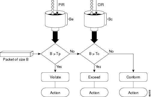
Examples
The following example shows how to configure two-rate traffic policing on a class to limit traffic to an average committed rate of 500 kbps and a peak rate of 1 Mbps:
Traffic marked as conforming to the average committed rate (500 kbps) will be sent as is. Traffic marked as exceeding 500 kbps, but not exceeding 1 Mbps, will be marked with IP Precedence 2 and then sent. All traffic marked as exceeding 1 Mbps will be dropped. The burst parameters are set to 10000 bytes.
In the following example, 1.25 Mbps of traffic is sent (“offered”) to a policer class:
The two-rate policer marks 500 kbps of traffic as conforming, 500 kbps of traffic as exceeding, and 250 kbps of traffic as violating the specified rate. Packets marked as conforming to the rate will be sent as is, and packets marked as exceeding the rate will be marked with IP Precedence 2 and then sent. Packets marked as violating the rate are dropped.
policy-map
To create or modify a policy map that can be attached to multiple ports to specify a service policy and to enter policy-map configuration mode, use the policy-map global configuration command. To delete an existing policy map and to return to global configuration mode, use the no form of this command.
Syntax Description
Command Default
Command Modes
Command History
|
|
|
|---|---|
This command was introduced on the Catalyst 4500 series switch. |
|
Extended support to Supervisor Engine 6-E and the Catalyst 4900M chassis. |
Usage Guidelines
Before configuring policies for classes whose match criteria are defined in a class map, use the policy-map command to specify the name of the policy map to be created or modified. After you enter the policy-map command, the switch enters policy-map configuration mode. You can configure or modify the class policies for that policy map and decide how to treat the classified traffic.
These configuration commands are available in policy-map configuration mode:
- class—D efines the classification match criteria for the specified class map. For more information, see the “class” section.
- description— Describes the policy map (up to 200 characters).
- exit— Exits policy-map configuration mode and returns you to global configuration mode.
- no— Removes a previously defined policy map.
To return to global configuration mode, use the exit command. To return to privileged EXEC mode, use the end command.
You can configure class policies in a policy map only if the classes have match criteria defined for them. To configure the match criteria for a class, use the class-map global configuration and match class-map configuration commands.
Examples
The following example shows how to configure multiple classes in a policy map called policymap2 on a Supervisor Engine 6-E:
The following example shows how to delete the policy map called policymap2:
You can verify your settings by entering the show policy-map privileged EXEC command.
Related Commands
port-channel auto
To enable the auto-lag feature on a switch globally, use the port-channel auto command in global configuration mode. To disable the auto-lag feature on the switch globally, use the no form of this command.
Syntax Description
Defaults
By default, the auto-LAG feature is disabled globally and is enabled on all port interfaces.
Command Modes
Command History
|
|
|
|---|---|
This command was introduced on the Catalyst 4500 series switch. |
Usage Guidelines
You can use the show etherchannel auto privileged EXEC command to verify if the EtherChannel was created automatically.
Examples
This example shows how to enable the auto-LAG feature on the switch:
Device(config)# port-channel auto
port-channel load-balance
To set the load-distribution method among the ports in the bundle, use the port-channel load-balance command. To reset the load distribution to the default, use the no form of this command.
port-channel load-balance method
Syntax Description
Specifies the load distribution method. See the “Usage Guidelines” section for more information. |
Command Default
Load distribution on the source XOR destination IP address is enabled.
Command Modes
Command History
|
|
|
|---|---|
This command was introduced on the Catalyst 4500 series switch. |
Usage Guidelines
The following values are valid for the load-distribution method:
- dst-ip —Load distribution on the destination IP address
- dst-mac —Load distribution on the destination MAC address
- dst-port —Load distribution on the destination TCP/UDP port
- src-dst-ip —Load distribution on the source XOR destination IP address
- src-dst-mac —Load distribution on the source XOR destination MAC address
- src-dst-port —Load distribution on the source XOR destination TCP/UDP port
- src-ip —Load distribution on the source IP address
- src-mac —Load distribution on the source MAC address
- src-port —Load distribution on the source port
Examples
The following example shows how to set the load-distribution method to the destination IP address:
Switch(config)# port-channel load-balance dst-ip
Switch(config)#
The following example shows how to set the load-distribution method to the source XOR destination IP address:
Switch(config)# port-channel load-balance src-dst-port
Switch(config)#
Related Commands
|
|
|
|---|---|
port-channel standalone-disable
To disable the EtherChannel standalone option in a port channel, use the port-channel standalone-disable command in interface configuration mode. To enable this option, use the no form of this command.
port-channel standalone-disable
no port-channel standalone-disable
Syntax Description
Command Default
Command Modes
Command History
|
|
|
|---|---|
This command was introduced on the Catalyst 4500 series switch. |
Usage Guidelines
This command can only be used when the port channel protocol type is Link Aggregation Control Protocol (LACP). It allows you to change the current behavior when a physical port cannot bundle with an LACP EtherChannel.
Examples
The following example shows how to enable the EtherChannel standalone option in a port channel:
Switch(config-if)# no port-channel standalone-disable
Related Commands
|
|
|
|---|---|
port-security mac-address
To configure a secure address on an interface for a specific VLAN or VLAN range, use the
port-securit y mac-address command.
port-security mac-address mac_address
Syntax Description
Command Modes
Command History
|
|
|
|---|---|
This command was introduced on the Catalyst 4500 series switch. |
Usage Guidelines
Layer 2 interfaces can be part of multiple VLANs (for example, a typical trunk port). In conjunction with the vlan command, you can use the port-security mac-address command to specify different addresses on different VLANs.
Examples
The following example shows how to configure the secure address 1.1.1 on interface Gigabit Ethernet 1/1 for VLANs 2-3:
Related Commands
|
|
|
|---|---|
Configures a sticky address on an interface for a specific VLAN or VLAN range. |
|
Configures the maximum number of addresses on an interface for a specific VLAN or VLAN range. |
port-security mac-address sticky
To configure a sticky address on an interface for a specific VLAN or VLAN range, use the
port-security mac-address sticky command.
port-security mac-address sticky mac_address
Syntax Description
Command Modes
Command History
|
|
|
|---|---|
This command was introduced on the Catalyst 4500 series switch. |
Usage Guidelines
The Sticky feature must be enabled on an interface before you can configure the
port-security mac-address sticky command.
Usage Guidelines
Layer 2 interfaces can be part of multiple VLANs (for example, a typical trunk port). In conjunction with the vlan command, you can use the port-security mac-address sticky command to specify different sticky addresses on different VLANs.
The Sticky feature must be enabled on an interface before you can configure the
port-security mac-address sticky command.
Sticky MAC addresses are addresses that persist across switch reboots and link flaps.
Examples
The following example shows how to configure the sticky address 1.1.1 on interface Gigabit Ethernet 1/1 for VLANs 2-3:
Related Commands
|
|
|
|---|---|
Configures a secure address on an interface for a specific VLAN or VLAN range. |
|
Configures the maximum number of addresses on an interface for a specific VLAN or VLAN range. |
port-security maximum
To configure the maximum number of addresses on an interface for a specific VLAN or VLAN range, use the port-security maximum command.
port-security maximum max_value
Syntax Description
Command Modes
Command History
|
|
|
|---|---|
This command was introduced on the Catalyst 4500 series switch. |
Usage Guidelines
Layer 2 interfaces can be part of multiple VLANs (for example, a typical trunk port). In conjunction with the vlan command, you can use the port-security maximum command to specify the maximum number of secure addresses on different VLANs.
If a specific VLAN on a port is not configured with a maximum value, the maximum configured for the port is used for that VLAN. In this situation, the maximum number of addresses that can be secured on this VLAN is limited to the maximum value configured on the port.
Each VLAN can be configured with a maximum count that is greater than the value configured on the port. Also, the sum total of the maximum configured values for all the VLANs can exceed the maximum configured for the port. In either of these situations, the number of MAC addresses secured on each VLAN is limited to the lesser of the VLAN configuration maximum and the port configuration maximum.
Examples
The following example shows how to configure a maximum number of addresses (5) on interface
Gigabit Ethernet 1/1 for VLANs 2-3:
Related Commands
|
|
|
|---|---|
Configures a secure address on an interface for a specific VLAN or VLAN range. |
|
Configures a sticky address on an interface for a specific VLAN or VLAN range. |
power dc input
To configure the power DC input parameters on the switch, use the power dc input command. To return to the default power settings, use the no form of this command.
Syntax Description
Sets the total capacity of the external DC source in watts; valid values are from 300 to 8500. |
Command Default
Command Modes
Command History
|
|
|
|---|---|
This command was introduced on the Catalyst 4500 series switch. |
|
Usage Guidelines
If your interface is not capable of supporting Power over Ethernet, you will receive this message:
Examples
The following example shows how to set the total capacity of the external DC power source to 5000 W:
Related Commands
|
|
|
|---|---|
power efficient-ethernet auto
To enable EEE, use the power efficient-ethernet auto command. To disable EEE, use the no form of this command.
no power efficient-ethernet auto
Syntax Description
Command Default
Command Modes
Command History
|
|
|
This command was introduced on the Catalyst 4500 series switch. |
Usage Guidelines
EEE is supported on WS-X4748-UPOE+E and WS-X4748-RJ45-E.
EEE defines support for physical layer devices (PHYs) to operate in Low Power Idle (LPI) mode. When enabled, EEE supports QUIET times during low link utilization allowing both sides of a link to disable portions of each PHY's operating circuitry and save power. This functionality is provided per port and is not enabled by default. To avoid issues with EEE functionality on any port during run-time, Cisco provides the power efficient-ethernet auto command to enable or disable EEE.
Because EEE relies on Auto Negotiation pulse to determine whether to activate EEE, the port must initially enable auto negotiation. Furthermore, EEE is the correct action provided the speed is auto 100M, auto 1000M, or auto 100M and 1000M. 10M (either auto or forced mode) does not require EEE for power saving.
Examples
The following example shows how to enable EEE:
power inline
To set the inline-power state for the inline-power-capable interfaces, use the power inline command. To return to the default values, use the no form of this command.
power inline { auto [ max milliwatt ] | never | static [ max milliwatt ] | consumption milliwatt }
Syntax Description
Command Default
Command Modes
Command History
|
|
|
|---|---|
This command was introduced on the Catalyst 4500 series switch. |
|
Maximum supported wattage increased beyond 15400 for the WS-X4648-RJ45V-E and the WS-X4648-RJ45V+E. |
Usage Guidelines
If your interface is not capable of supporting Power over Ethernet, you will receive this message:
Examples
The following example shows how to set the inline-power detection and power for the inline-power-capable interfaces:
Switch(config-if)# end
The following example shows how to disable the inline-power detection and power for the inline-power-capable interfaces:
Switch(config-if)# end
The following example shows how to set the permanent Power over Ethernet allocation to 8000 mW for Fast Ethernet interface 4/1 regardless what is mandated either by the 802.3af class of the discovered device or by any CDP packet that is received from the powered device:
Switch(config-if)# power inline consumption 8000
Switch(config-if)# end
The following example shows how to pre-allocate Power over Ethernet to 16500 mW for Gigabit Ethernet interface 2/1 regardless of what is mandated either by the 802.3af class of the discovered device or by any CDP packet that is received from the powered device:
Related Commands
|
|
|
|---|---|
power inline consumption
To set the default power that is allocated to an interface for all the inline-power-capable interfaces on the switch, use the power inline consumption command. To return to the default values, use the no form of this command.
power inline consumption default milliwatts
no power inline consumption default
Syntax Description
Sets the default power allocation in milliwatts; the valid range is from 4000 to 15399. Any non-default value disables automatic adjustment of power allocation. |
Command Default
Command Modes
Command History
|
|
|
|---|---|
This command was introduced on the Catalyst 4500 series switch. |
|
Usage Guidelines
The inline power consumption command overrides the power allocated to the port through IEEE/Cisco phone discovery and CDP/LLDP power negotiation. To guarantee safe operation of the system, ensure that the value configured here is no less than the actual power requirement of the attached device. If the power drawn by the inline powered devices exceeds the capability of the power supply, it could trip the power supply.
If your interface is not capable of supporting Power over Ethernet, you will receive this message:
Examples
The following example shows how to set the Power over Ethernet allocation to use 8000 mW, regardless of any CDP packet that is received from the powered device:
Switch(config)# end
Related Commands
|
|
|
|---|---|
Sets the inline-power state for the inline-power-capable interfaces. |
|
power inline four-pair forced
Note![]() This command is available only on Supervisor Engine 7-E, Supervoisor Engine 7L-E, and Supervisor Engine 8-E.
This command is available only on Supervisor Engine 7-E, Supervoisor Engine 7L-E, and Supervisor Engine 8-E.
To automatically enable power on both signal and spare pairs from a switch port, provided the end-device is PoE capable on both signal and spare pairs but does not support the CDP or LLDP extensions required for UPOE, use the power inline four-pair forced command.
Syntax Description
Command Default
Command Modes
Command History
|
|
|
|---|---|
This command was introduced on the Catalyst 4500 series switch using a Supervisor Engine 7-E and 7L-E. |
Usage Guidelines
Although IEEE 802.at only provides for power up to 30W per port, the WS-X4748-UPOE+E module can provide up to 60W using the spare pair of an RJ45 cable (wires 4,5,7,8) with the signal pair (wires 1,2,3,6). Power on the spare pair is enabled when the switch port and end-device mutually identify themselves as UPOE capable using CDP or LLDP and the end-device requests for power on the spare pair to be enabled. When the spare pair is powered, the end-device can negotiate up to 60W power from the switch using CDP or LLDP.
If the end-device is PoE capable on both signal and spare pairs but does not support the CDP or LLDP extensions required for UPOE, then the following configuration automatically enables power on both signal and spare pairs from the switch port
Examples
The following example shows how to automatically enable power on both signal and spare pairs from switch port gigabit ethernet 2/1:
Do not enter this command if the end-device is incapable of sourcing inline power on the spare pair or if the end-device supports the CDP or LLDP extensions for UPOE.
power inline logging global
To enable console messages that show when a PoE device has been detected and to show when a PoE device has been removed, use the power inline logging global command.
Syntax Description
Command Default
Command Modes
Command History
|
|
|
|---|---|
This command was introduced on the Catalyst 4500 series switch. |
Usage Guidelines
Be aware of the potential for console flooding if this command is used on a switch connected to several PoE devices.
Examples
The following example shows how to globally enable PoE status messaging on each interface:
To enable PoE event logging, you use the logging event poe-status global command:
Related Commands
|
|
|
|---|---|
Changes the default switch-wide global link-status event messaging settings. |
power inline police
To configure Power over Ethernet policing on a particular interface, use the power inline police command. The no form of the command disables PoE policing on an interface.
power inline police [action] [errdisable | log]
no power inline police [action] [errdisable | log]
Syntax Description
Command Default
Command Modes
Command History
|
|
|
|---|---|
This command was introduced on the Catalyst 4500 series switch. |
Usage Guidelines
If a port is in the errdisable state because of a PoE policing fault, enter the shut command followed by a no shut on the interface to make the port operational again.
You can also configure inline-power errdisable autorecovery so that an errdisabled interface is automatically revived when the errdisable autorecovery timer expires.
Examples
The following example shows how to enable PoE policing and configure a policing action:
Related Commands
power redundancy combined max inputs
To configure the power settings for the chassis specifically for 'Combined Mode Resiliency', use the power redundancy combined max inputs command. To return to the default setting, use the default form of this command.
Note![]() This feature only applies in combined mode when both power supply bays contain the 4200 W AC, 6000 W AC, or 9000W power supply.
This feature only applies in combined mode when both power supply bays contain the 4200 W AC, 6000 W AC, or 9000W power supply.
power redundancy combined max inputs {x | y}
default power redundancy combined max inputs
Syntax Description
Command Default
Command Modes
Command History
|
|
|
|---|---|
This command was introduced on the Catalyst 4500 series switch. |
Usage Guidelines
Using the combined mode power resiliency feature, you can limit the power usage to a maximum of two or three (configurable) inputs for 4000W and 6000W power supplies. For 9000W power supplies, you can limit the power usage to a maximum of 2 to 5 inputs, since the 9000W is a triple input power supply.
With two 4200 W AC or 6000 W AC power supplies, a maximum of four inputs are available. With two 9000W, a maximum of six inputs are available. This feature allows you to cap the power usage to that of two/three inputs or four/five inputs. If one of the power supplies fails, no loss of power occurs because you have capped its usage to a smaller number of inputs.
If you have max inputs 3 configured with four "good" (220 V) inputs and you limit the user to 5500 W instead of 7600 W and one subunit fails or is powered off, you have three quality inputs providing 5500 W and the chassis is powered at the same rate as it was prior to the failure event:
Here is the output of the show power command prior to invoking this feature:
Here is the output after invoking this feature. The combined mode was indicated before
Power supplies needed = 2 in the output of the show power command, combined mode is now indicated by the phrase Power supplies needed by system: 2 Maximum Inputs = 3.
Here's another example of combined mode resiliency with 9000W power supply with a maximum of six active inputs, limited to 3 inputs:
Examples
The following example shows how to configure the combined mode resiliency feature when a 9000W AC power supply is detected.
Note![]() The power usage is limited to four or five inputs.
The power usage is limited to four or five inputs.
Note![]() The maximum inputs part of the command is ignored by all power supplies other than 9000 W AC.
The maximum inputs part of the command is ignored by all power supplies other than 9000 W AC.
The following example shows how to configure the combined mode resiliency feature if f a 9000W AC power supply is not detected.
Note![]() The power usage is limited to two or three inputs.
The power usage is limited to two or three inputs.
Note![]() The maximum inputs part of the command is ignored by all power supplies other than the 4200 W AC or 6000 W AC.
The maximum inputs part of the command is ignored by all power supplies other than the 4200 W AC or 6000 W AC.
Related Commands
|
|
|
|---|---|
power redundancy-mode
To configure the power settings for the chassis, use the power redundancy-mode command. To return to the default setting, use the default form of this command.
power redundancy-mode { redundant | combined }
Syntax Description
Command Default
Command Modes
Command History
|
|
|
|---|---|
This command was introduced on the Catalyst 4500 series switch. |
Usage Guidelines
The two power supplies must be the same type and wattage.
In redundant mode, the power from a single power supply must provide enough power to support the switch configuration.
Table 2-12 lists the maximum available power for chassis and Power over Ethernet for each power supply.
|
|
|
|
|
|---|---|---|---|
Chassis1 = 1050 |
|||
| PoE (max)2 = (DC Input3 - [Chassis (min) + Backplane] / 0.75) * 0.96 |
Chassis = 22674 PoE5 |
||
| PoE = 06 |
|||
Chassis7—9/11 PoE8—2/3 |
Special Considerations for the 4200 W AC, 6000 W AC, and 9000W Power Supplies
The 4200 W AC and 6000 W AC power supply has two inputs: each can be powered at 110 or 220 V.
The 9000 W AC power supply has three inputs: each can be powered at 110 or 220V.
As with other power supplies, the two power supplies must be of the same type (6000 W AC or 4200 W AC or 9000 W AC). Otherwise, the right power supply is put in err-disable state and the left one is selected. In addition, all the inputs to the chassis must be at the same voltage. In redundant mode, the inputs to the left and right power supplies must be identical. If the left and right power supplies are powered in redundant mode, the power values is based on the power supply with the higher output wattage.
Note![]() When the system is powered with a 4200 W, 6000 W, or 9000W power supply either in 110 V or 220 V combined mode operation, the available power is determined by the configuration of the system (the type of line cards, the number of line cards, number of ports consuming inline power, etc.) and does not reflect the absolute maximum power.
When the system is powered with a 4200 W, 6000 W, or 9000W power supply either in 110 V or 220 V combined mode operation, the available power is determined by the configuration of the system (the type of line cards, the number of line cards, number of ports consuming inline power, etc.) and does not reflect the absolute maximum power.
Note![]() In a matched redundant power supply configuration, if a power supply submodule fails, the other (good) power supply provides power to its full capability.
In a matched redundant power supply configuration, if a power supply submodule fails, the other (good) power supply provides power to its full capability.
Examples
The following example shows how to set the power management mode to combined:
Switch(config)# power redundancy-mode combined
Switch(config)#
Related Commands
|
|
|
|---|---|
pppoe intermediate-agent (global)
To enable the PPPoE Intermediate Agent feature on a switch, use the pppoe intermediate-agent global configuration command. To disable the feature, use the no form of this command.
Syntax Description
Command Default
Command Modes
Command History
|
|
|
|---|---|
This command was introduced on the Catalyst 4500 series switch. |
Usage Guidelines
You must enable PPPoE Intermediate Agent globally on a switch before you can use
PPPoE Intermediate Agent on an interface or interface VLAN.
Examples
The following example shows how to enable PPPoE Intermediate Agent on a switch:
The following example shows how to disable PPPoE Intermediate Agent on a switch:
Related Commands
|
|
|
|---|---|
Sets the access node identifier, generic error message, and identifier string for a switch. |
pppoe intermediate-agent (interface)
Note![]() This command takes effect only if you enable the pppoe intermediate-agent global command.
This command takes effect only if you enable the pppoe intermediate-agent global command.
To enable the PPPoE Intermediate Agent feature on an interface, use the pppoe intermediate-agent command. To disable the feature, use the no form of this command.
Syntax Description
Command Default
Command Modes
Command History
|
|
|
|---|---|
This command was introduced on the Catalyst 4500 series switch. |
Usage Guidelines
PPPoE Intermediate Agent is enabled on an interface provided the PPPoE Intermediate Agent is enabled both on the switch and the interface.
Examples
The following example shows how to enable the PPPoE Intermediate Agent on an interface:
The following example shows how to disable the PPPoE Intermediate Agent on an interface:
Related Commands
|
|
|
|---|---|
Limits the rate of the PPPoE Discovery packets coming on an interface. |
|
Enables vendor-tag stripping on PPPoE Discovery packets from PPPoE Server (or BRAS). |
pppoe intermediate-agent (interface vlan-range)
Note![]() This command takes effect only if you enable the pppoe intermediate-agent global command.
This command takes effect only if you enable the pppoe intermediate-agent global command.
To enable PPPoE Intermediate Agent on an interface VLAN range, use the pppoe intermediate-agent global command. To disable the feature, use the no form of this command.
Syntax Description
Command Default
Command Modes
Interface vlan-range configuration mode
Command History
|
|
|
|---|---|
This command was introduced on the Catalyst 4500 series switch. |
Usage Guidelines
Although this command takes effect irrespective of the pppoe intermediate-agent (interface configuration mode) command, you must enable the pppoe intermediate-agent (global configuration mode) command.
Examples
The following example shows how to enable PPPoE Intermediate Agent on a range of VLANs:
The following example shows how to disable PPPoE Intermediate Agent on a single VLAN:
Related Commands
|
|
|
|---|---|
Enables the PPPoE Intermediate Agent feature on an interface. |
pppoe intermediate-agent format-type (global)
To set the access node identifier, generic error message, and identifier string for the switch, use the
pppoe intermediate-agent format-type (global) command. To disable the feature, use the no form of this command:
pppoe intermediate-agent format-type access-node-identifier string string
pppoe intermediate-agent format-type generic-error-message string string
pppoe intermediate-agent format-type identifier-string string string option {sp|sv|pv|spv} delimiter {,|.|;|/|#}
no pppoe intermediate-agent format-type {access-node-identifier | generic-error-message | identifier-string}
Syntax Description
Command Default
access-node-identifier has a default value of 0.0.0.0.
generic-error-message, identifier-string, option, and delimiter have no default values.
Command Modes
Command History
|
|
|
|---|---|
This command was introduced on the Catalyst 4500 series switch. |
Usage Guidelines
Use the access-node-identifier and identifier-string commands to enable the switch to generate the circuit-id parameters automatically.
The no form of identifier-string command unsets the option and delimiter.
Use the generic-error-message command to set an error message notifying the sender that the
PPPoE Discovery packet was too large.
Examples
The following example shows how to set an access-node-identifier:
The following example shows how to unset a generic-error-message:
Related Commands
|
|
|
|---|---|
Displays the PPPoE Intermediate Agent configuration and statistics (packet counters). |
pppoe intermediate-agent format-type (interface)
Note![]() This command takes effect only if you enable the pppoe intermediate-agent interface configuration command.
This command takes effect only if you enable the pppoe intermediate-agent interface configuration command.
To set circuit-id or remote-id for an interface, use the pppoe intermediate-agent format-type command. To unset the parameters, use the no form of this command.
pppoe intermediate-agent format-type {circuit-id | remote-id} string string
no pppoe intermediate-agent format-type {circuit-id | remote-id} string string
Syntax Description
Command Default
Command Modes
Command History
|
|
|
|---|---|
This command was introduced on the Catalyst 4500 series switch. |
Usage Guidelines
Use the pppoe intermediate-agent format-type command to set interface-specific circuit-id and remote-id values. If an interface-specific circuit-id is not set, the system's automatic generated circuit-id value is used.
Examples
The following example shows how to set remote-id for an interface:
The following example shows how to unset circuit-id for an interface:
Related Commands
|
|
|
|---|---|
Enables the PPPoE Intermediate Agent feature on an interface. |
|
Sets the circuit-id or remote-id for an interface vlan-range. |
pppoe intermediate-agent format-type (interface vlan-range)
Note![]() This command takes effect only if you enable the pppoe intermediate-agent interface vlan-range configuration mode command.
This command takes effect only if you enable the pppoe intermediate-agent interface vlan-range configuration mode command.
To set circuit-id or remote-id for an interface vlan-range, use the
pppoe intermediate-agent format-type interface vlan-range mode command. To unset the parameters, use the no form of this command.
pppoe intermediate-agent format-type {circuit-id | remote-id} string string
no pppoe intermediate-agent format-type {circuit-id | remote-id} string string
Syntax Description
Command Default
Command Modes
Interface vlan-range configuration mode
Command History
|
|
|
|---|---|
This command was introduced on the Catalyst 4500 series switch. |
Usage Guidelines
Use these commands to set circuit-id or remote-id on an interface vlan-range. If the circuit-id is not set, the system’s automatically generated circuit-id is used.
Examples
The following example shows how to set remote-id on an interface VLAN:
pppoe intermediate-agent format-type remote-id string user5551983-cabletv
The following example shows how to unset circuit-id on an interface vlan-range:
Related Commands
|
|
|
|---|---|
Enables PPPoE Intermediate Agent on an interface VLAN range. |
pppoe intermediate-agent limit rate
To limit the rate of the PPPoE Discovery packets arriving on an interface, use the
pppoe intermediate-agent limit rate command. To disable the feature, use the no form of this command.
pppoe intermediate-agent limit rate number
no pppoe intermediate-agent limit rate number
Syntax Description
Specifies the threshold rate of PPPoE Discovery packets received on this interface in packets-per-second. |
Command Default
Command Modes
Command History
|
|
|
|---|---|
This command was introduced on the Catalyst 4500 series switch. |
Usage Guidelines
If this command is used and the PPPoE Discovery packets that are received exceeds the rate set, the interface will be error-disabled (shutdown).
Examples
The following example shows how to set a rate limit for an interface:
The following example shows how to disable rate limiting for an interface:
Related Commands
|
|
|
|---|---|
Enables the PPPoE Intermediate Agent feature on an interface |
pppoe intermediate-agent trust
To set the trust configuration of an interface, use the pppoe intermediate-agent trust global command. To unset the trust parameter, use the no form of this command.
pppoe intermediate-agent trust
no pppoe intermediate-agent trust
Syntax Description
Command Default
Command Modes
Command History
|
|
|
|---|---|
This command was introduced on the Catalyst 4500 series switch. |
Usage Guidelines
At least one trusted interface must be present on the switch for PPPoE Intermediate Agent feature to work.
Set the interface connecting the switch to the PPPoE Server (or BRAS) as trusted.
Examples
The following example shows how to set an interface as trusted:
The following example shows how to disable the trust configuration for an interface:
Related Commands
|
|
|
|---|---|
Enables vendor-tag stripping on PPPoE Discovery packets from a PPPoE Server (or BRAS). |
pppoe intermediate-agent vendor-tag strip
Note![]() This command takes effect only if you enable the pppoe intermediate-agent interface configuration command and the pppoe intermediate-agent trust command.
This command takes effect only if you enable the pppoe intermediate-agent interface configuration command and the pppoe intermediate-agent trust command.
To enable vendor-tag stripping on PPPoE Discovery packets from PPPoE Server (or BRAS), use the
pppoe intermediate-agent vendor-tag strip command. To disable this setting, use the no form of this command.
pppoe intermediate-agent vendor-tag strip
no pppoe intermediate-agent vendor-tag strip
Syntax Description
Command Default
Command Modes
Command History
|
|
|
|---|---|
This command was introduced on the Catalyst 4500 series switch. |
Usage Guidelines
This command has no effect on untrusted interfaces.
Use this command on a PPPoE Intermediate Agent trusted interface to strip off the vendor-specific tags in PPPoE Discovery packets that arrive downstream from the PPPoE Server (or BRAS), if any.
Examples
The following example shows how to set vendor-tag stripping on an interface:
The following example shows how to disable vendor-tag stripping on an interface:
Related Commands
|
|
|
|---|---|
Enables the PPPoE Intermediate Agent feature on an interface. |
|
priority
To enable the strict priority queue (low-latency queueing [LLQ]) and to give priority to a class of traffic belonging to a policy map attached to a physical port, use the priority policy-map class configuration command. To return to the default setting, use the no form of this command.
Syntax Description
Command Default
Command Modes
Policy-map class configuration mode
Command History
|
|
|
|---|---|
Support introduced on Supervisor Engine 6E and Catalyst 4900M. |
Usage Guidelines
Use the priority command only in a policy map attached to a physical port. You can use this command only in class-level classes, you cannot use this command in class class-default.
This command configures LLQ and provides strict-priority queueing. Strict-priority queueing enables delay-sensitive data, such as voice, to be sent before packets in other queues are sent. The priority queue is serviced first until it is empty.
You cannot use the bandwidth , dbl , and the shape policy-map class configuration commands with the priority policy-map class configuration command in the same class within the same policy map. However, you can use these commands in the same policy map.
You can use police or set class configuration commands with the priority police-map class configuration command.
If the priority queuing class is not rate limited, you cannot use the bandwidth command, you can use the bandwidth remaining percent command instead.
Examples
The following example shows how to enable the LLQ for the policy map called policy1 :
You can verify your settings by entering the show policy-map privileged EXEC command.
Related Commands
private-vlan
To configure private VLANs and the association between a private VLAN and a secondary VLAN, use the private-vlan command. To return to the default value, use the no form of this command.
private-vlan { isolated | community | twoway-community | primary }
private-vlan association secondary-vlan-list [{ add secondary-vlan-list } | { remove secondary-vlan-list }]
no private-vlan { isolated | community | twoway-community | primary }
Syntax Description
Command Default
Command Modes
Command History
|
|
|
|---|---|
This command was introduced on the Catalyst 4500 series switch. |
|
Usage Guidelines
You cannot configure VLAN 1 or VLANs 1001 to 1005 as private VLANs.
VTP does not support private VLANs. You must configure private VLANs on each device where you want private VLAN ports.
The secondary_vlan_list parameter cannot contain spaces; it can contain multiple comma-separated items. Each item can be a single private VLAN ID or a range of private VLAN IDs separated by hyphens.
The secondary_vlan_list parameter can contain multiple community VLAN IDs.
The secondary_vlan_list parameter can contain only one isolated VLAN ID. A private VLAN is defined as a set of private ports characterized by a common set of VLAN number pairs: each pair is made up of at least two special unidirectional VLANs and is used by isolated ports or by a community of ports to communicate with the switches.
An isolated VLAN is a VLAN that is used by the isolated ports to communicate with the promiscuous ports. The isolated VLAN traffic is blocked on all other private ports in the same VLAN and can be received only by the standard trunking ports and the promiscuous ports that are assigned to the corresponding primary VLAN.
A community VLAN is the VLAN that carries the traffic among the community ports and from the community ports to the promiscuous ports on the corresponding primary VLAN. A community VLAN is not allowed on a private VLAN trunk.
A promiscuous port is a private port that is assigned to a primary VLAN.
A primary VLAN is a VLAN that is used to convey the traffic from the switches to the customer end stations on the private ports.
You can specify only one isolated vlan-id value, while multiple community VLANs are allowed. You can only associate isolated and community VLANs to one VLAN. The associated VLAN list may not contain primary VLANs. Similarly, a VLAN that is already associated to a primary VLAN cannot be configured as a primary VLAN.
The private-vlan commands do not take effect until you exit the config-VLAN submode.
If you delete either the primary or secondary VLAN, the ports that are associated with the VLAN become inactive.
Refer to the Catalyst 4500 Series Switch Cisco IOS Software Configuration Guide for additional configuration guidelines.
Examples
The following example shows how to configure VLAN 202 as a primary VLAN and verify the configuration:
The following example shows how to configure VLAN 303 as a community VLAN and verify the configuration:
The following example shows how to configure VLAN 440 as an isolated VLAN and verify the configuration:
The following example shows how to create a private VLAN relationship among the primary VLAN 14, the isolated VLAN 19, and community VLANs 20 and 21:
The following example shows how to remove a private VLAN relationship and delete the primary VLAN. The associated secondary VLANs are not deleted.
The following example shows how to configure VLAN 550 as a twoway-community VLAN and verify the configuration:
The following example shows how to associate community VLANs 303 through 307 and 309 and isolated VLAN 440 with primary VLAN 202 and verify the configuration:
Note![]() The secondary VLAN 308 has no associated primary VLAN.
The secondary VLAN 308 has no associated primary VLAN.
The following example shows how to remove an isolated VLAN from the private VLAN association:
The following example shows how to configure interface FastEthernet 5/1 as a PVLAN host port and verify the configuration:
Related Commands
|
|
|
|---|---|
private-vlan mapping
To create a mapping between the primary and the secondary VLANs so that both share the same primary VLAN SVI, use the private-vlan mapping command. To remove all PVLAN mappings from an SVI, use the no form of this command.
private-vlan mapping primary-vlan-id {[ secondary-vlan-list | { add secondary-vlan-list } | { remove secondary-vlan-list }]}
Syntax Description
(Optional) VLAN ID of the secondary VLANs to map to the primary VLAN. |
|
(Optional) Removes the mapping between the secondary VLAN and the primary VLAN. |
Command Default
Command Modes
Command History
|
|
|
|---|---|
This command was introduced on the Catalyst 4500 series switch. |
Usage Guidelines
The secondary_vlan_list parameter cannot contain spaces. It can contain multiple, comma-separated items. Each item can be a single PVLAN ID or a range of PVLAN IDs separated by hyphens.
This command is valid in the interface configuration mode of the primary VLAN.
The SVI of the primary VLAN is created at Layer 3.
The traffic that is received on the secondary VLAN is routed by the SVI of the primary VLAN.
The SVIs of the existing secondary VLANs do not function and are considered down after this command is entered.
A secondary SVI can be mapped to only one primary SVI. If the configured PVLANs association is different from what is specified in this command (if the specified primary-vlan-id is configured as a secondary VLAN), all the SVIs that are specified in this command are brought down.
If you configure a mapping between two VLANs that do not have a valid Layer 2 association, the mapping configuration does not take effect.
Examples
The following example shows how to map the interface of VLAN 20 to the SVI of VLAN 18:
Switch(config)# interface vlan 18
Switch(config-if)# private-vlan mapping 18 20
Switch(config-if)#
The following example shows how to permit the routing of the secondary VLAN ingress traffic from PVLANs 303 through 307, 309, and 440 and how to verify the configuration:
Switch# config terminal
Switch(config)# interface vlan 202
Switch(config-if)# private-vlan mapping add 303-307,309,440
Switch(config-if)# end
Switch# show interfaces private-vlan mapping
Interface Secondary VLAN Type
--------- -------------- -----------------
vlan202 303 isolated
vlan202 304 isolated
vlan202 305 isolated
vlan202 306 isolated
vlan202 307 isolated
vlan202 309 isolated
vlan202 440 isolated
Switch#
The following example shows the displayed message that you will see if the VLAN that you are adding is already mapped to the SVI of VLAN 18. You must delete the mapping from the SVI of VLAN 18 first.
Switch(config)# interface vlan 19
Switch(config-if)# private-vlan mapping 19 add 21
Switch(config-if)#
The following example shows how to remove all PVLAN mappings from the SVI of VLAN 19:
Switch(config)# interface vlan 19
Switch(config-if)# no private-vlan mapping
Related Commands
|
|
|
|---|---|
private-vlan synchronize
To map the secondary VLANs to the same instance as the primary VLAN, use the private-vlan synchronize command.
Syntax Description
Command Default
Command Modes
Command History
|
|
|
|---|---|
This command was introduced on the Catalyst 4500 series switch. |
Usage Guidelines
If you do not map the VLANs to the same instance as the associated primary VLAN when you exit the MST configuration submode, a warning message displays and lists the secondary VLANs that are not mapped to the same instance as the associated primary VLAN. The private-vlan synchronize command automatically maps all secondary VLANs to the same instance as the associated primary VLANs.
Examples
The following example shows how to initialize PVLAN synchronization:
This example assumes that a primary VLAN 2 and a secondary VLAN 3 are associated to VLAN 2, and that all VLANs are mapped to the CIST instance 1. This example also shows the output if you try to change the mapping for the primary VLAN 2 only:
Related Commands
|
|
|
|---|---|
profile
To enter profile call-home configuration submode, use the profile command in call-home configuration mode, use the profile command.
Syntax Description
Command Default
Command Modes
Command History
|
|
|
|---|---|
This command was introduced on the Catalyst 4500 series switch. |
Usage Guidelines
When you enter the profile profile_name command in call-home mode, the prompt changes to Switch(cfg-call-home-profile)#, and you have access to the following profile configuration commands:
- active
- destination address
- destination message-size-limit bytes
- destination preferred-msg-format
- destination transport-method
- end
- exit
- subscribe-to-alert-group all
- subscribe-to-alert-group configuration
- subscribe-to-alert-group diagnostic
- subscribe-to-alert-group environment
- subscribe-to-alert-group inventory
- subscribe-to-alert-group syslog
Examples
The following example shows how to create and configure a user-defined call-home profile:
Related Commands
profile flow
To enable Media Services Proxy (MSP), use the the profile flow command. To return to the default setting, use the no form of this command
Command Default
Command Modes
Command History
|
|
|
|---|---|
This command was introduced on the Catalyst 4500 series switch. |
Usage Guidelines
You must configure the MSP profile flow command to activate the MSP platform Packet parser. This is because the the MSP device handler is tightly coupled with MSP flow parser. Not enabling this CLI means that MSP will not send SIP, H323 notifications to IOS sensor.
Examples
The following example shows how to enable MSP:
qos account layer-all encapsulation
To account for Layer 1 header length of 20 bytes in QoS policing features, use the qos account layer-all encapsulation command. To disable the use of additional bytes, use the no form of this command.
qos account layer-all encapsulation
no qos account layer-all encapsulation
Syntax Description
Command Default
On Supervisor Engine 6-E, Supervisor Engine 6L-E, Catalyst 4900M, Catalyst 4948E, and Catalyst 4948E-F, policers account only for the Layer 2 header length in policing features. In contrast, in rate calculations, shapers account for header length as well as IPG.
Command Modes
Command History
|
|
|
|---|---|
This command was introduced on the Catalyst 4500 series switch. |
Usage Guidelines
Supervisor Engine 6-E, Supervisor Engine 6L-E, Catalyst 4900M, Catalyst 4948E, and Catalyst 4948E-F use the qos account layer-all encapsulation command to account for Layer 1 header of 20 bytes ( preamble + IPG) and Layer 2 header in policing features. When this command is configured, policer statistics ( in bytes) observed in the output of the show policy-map interface command reflect the Layer 1 header length as well ( 20 bytes per packet).
Examples
The following example shows how to shows how to include IPG in policing:
Related Commands
|
|
|
|---|---|
qos account layer2 encapsulation
To include additional bytes to be accounted by the QoS features, use the qos account layer2 encapsulation command. To disable the use of additional bytes, use the no form of this command.
qos account layer2 encapsulation { arpa | dot1q | isl | length len }
no qos account layer2 encapsulation { arpa | dot1q | isl | length len }
Syntax Description
Command Default
On Supervisor Engine 6E, Supervisor Engine 6L-E, the length that is specified in the Ethernet header is considered for both IP and non-IP packets. The Layer 2 length includes the VLAN tag overhead.
Command Modes
Command History
|
|
|
|---|---|
This command was introduced on the Catalyst 4500 series switch. |
Usage Guidelines
On Supervisor Engine 6E, Supervisor Engine 6L-E, shaping and sharing always use Ethernet ARPA length to which 20 bytes of IPv6 overhead is always added for policing. However, only Layer 2 length including VLAN tag overhead is considered.
Note![]() The given length is included when policing all IP packets irrespective of the encapsulation with which it was received. When qos account layer2 encapsulation isl is configured, a fixed length of 48 bytes is included when policing all IP packets, not only those IP packets that are received with ISL encapsulation.
The given length is included when policing all IP packets irrespective of the encapsulation with which it was received. When qos account layer2 encapsulation isl is configured, a fixed length of 48 bytes is included when policing all IP packets, not only those IP packets that are received with ISL encapsulation.
Sharing and shaping use the length that is specified in the Layer 2 headers.
Examples
The following example shows how to include an additional 18 bytes when policing IP packets:
The following example shows how to disable the consistent accounting of the Layer 2 encapsulation by the QoS features:
Related Commands
|
|
|
|---|---|
Modifies the switching characteristics of a Layer 2 switch interface. |
|
Prevents the unknown multicast or unicast packets from being forwarded. |
qos trust
To set the trusted state of an interface (for example, whether the packets arriving at an interface are trusted to carry the correct CoS, ToS, and DSCP classifications), use the qos trust command. To set an interface to the untrusted state, use the no form of this command.
qos trust { cos | device cisco-phone | dscp | extend [ cos priority ]}
no qos trust { cos | device cisco-phone | dscp | extend [ cos priority ]}
Syntax Description
Command Default
Command Modes
Command History
|
|
|
|---|---|
This command was introduced on the Catalyst 4500 series switch. |
|
Usage Guidelines
You can only configure the trusted state on physical LAN interfaces.
A trusted boundary should not be configured on ports that are part of an EtherChannel (that is, a port channel).
By default, the trust state of an interface when QoS is enabled is untrusted; when QoS is disabled on the interface, the trust state is reset to trust DSCP.
When the interface trust state is qos trust cos, the transmit CoS is always the incoming packet CoS (or the default CoS for the interface, if the packet is not tagged).
When the interface trust state is not qos trust dscp, the security and QoS ACL classification will always use the interface DSCP and not the incoming packet DSCP.
Examples
The following example shows how to set the trusted state of an interface to CoS:
The following example shows how to set the trusted state of an interface to DSCP:
The following example shows how to set the PVID CoS level to 6:
The following example shows how to set the Cisco phone as the trust device:
Related Commands
|
|
|
|---|---|
queue-limit
To specify or modify the maximum number of packets the queue can hold for a class policy configured in a policy map, use the queue-limit command. To remove the queue packet limit from a class, use the no form of this command.
no queue-limit number-of-packets
Syntax Description
Number of packets that the queue for this class can accumulate; valid range is 16 to 8184. This number must be a multiple of 8. |
Command Default
By default, each physical interface on a Catalyst 4500 switch has a default queue based on the number of slots in a chassis and the number of ports on the linecards.
Command Modes
QoS policy-map class configuration mode
Command History
|
|
|
|---|---|
This command was introduced on the Catalyst 4500 series switch. |
Usage Guidelines
The class-based queuing (CBQ) command applies only to the Supervisor Engine 6-E and Catalyst Engine 6L-E as part of MQC support on the Catalyst 4500 switch.
By default, each physical interface on a Catalyst 4500 switch comes up with a default queue. The size of this queue is based on the number of slots in a chassis as well as the number of ports on the line card in each slot. The switch supports 512K queue entries of which 100 K are set aside as a common sharable pool. The remaining 412 K entries are equally distributed among the slots. Each slot further divides its allocated queue entries equally among its ports.
CBQ creates a queue for every class for which a class map is defined. Packets satisfying the match criterion for a class accumulate in the queue reserved for the class until they are sent, which occurs when the queue is serviced by the fair queuing process. When the maximum packet threshold you defined for the class is reached, queuing of any further packets to the class queue causes tail drop or, if DBL is configured for the class policy, packet drop to take effect.
Note![]() The queue-limit command is supported only after you first configure a scheduling action, such as bandwidth, or priority, except when you configure queue-limit in the class-default class of an output QoS policy-map.s
The queue-limit command is supported only after you first configure a scheduling action, such as bandwidth, or priority, except when you configure queue-limit in the class-default class of an output QoS policy-map.s
Examples
The following example shows how to configure a policy-map called policy11 to contain policy for a class called acl203. Policy for this class is set so that the queue reserved for it has a maximum packet limit of 40:
Related Commands
redundancy
To enter the redundancy configuration mode, use the redundancy command in the global configuration mode.
Syntax Description
Command Default
Command Modes
Command History
|
|
|
|---|---|
This command was introduced on the Catalyst 4500 series switch (Catalyst 4507R and 4510R only). |
Usage Guidelines
The redundancy configuration mode is used to enter the main CPU submode.
To enter the main CPU submode, use the main-cpu command in the redundancy configuration mode.
The main CPU submode is used to manually synchronize the configurations on the two supervisor engines.
From the main CPU submode, use the auto-sync command to enable automatic synchronization of the configuration files in NVRAM.
Use the no command to disable redundancy. If you disable redundancy, then reenable redundancy, the switch returns to default redundancy settings.
Use the exit command to exit the redundancy configuration mode.
Examples
The following example shows how to enter redundancy mode:
The following example shows how to enter the main CPU submode:
Switch(config)# redundancy
Switch(config-red)# main-cpu
Switch(config-r-mc)#
Related Commands
|
|
|
|---|---|
Enables automatic synchronization of the configuration files in NVRAM. |
|
Enters the main CPU submode and manually synchronize the configurations on the two supervisor engines. |
redundancy config-sync mismatched-commands
To move the active supervisor engine into the Mismatched Command List (MCL) and resets the standby supervisor engine, use the redundancy config-sync mismatched-commands command.
If your active and standby supervisors engines are running different versions of Cisco IOS, some of their CLIs will not be compatible. If such commands are already present in the running configuration of the active supervisor engine and the syntax-check for the command fails at the standby supervisor engine while it is booting, you must move the active supervisor engine into the Mismatched Command List (MCL).
redundancy config-sync { ignore | validate } mismatched-commands
Syntax Description
Revalidate the mismatched command list with the modified running-configuration. |
Command Default
Command Modes
Command History
|
|
|
|---|---|
This command was introduced on the Catalyst 4500 series switch. |
|
Updated command name from issu config-sync to redundancy config-sync. |
Usage Guidelines
The following is a log entry example for mismatched commands:
To display all mismatched commands, use the show redundancy config-sync failures mcl command.
To clean the MCL, remove all mismatched commands from the active supervisor engine’s running configuration, revalidate the MCL with a modified running configuration using the redundancy config-sync validate mismatched-commands command, then reload the standby supervisor engine.
You could also ignore the MCL by entering the redundancy config-sync ignore mismatched-commands command and reloading the standby supervisor engine; the system changes to SSO mode.
Note![]() If you ignore the mismatched commands, the out-of-sync configuration at the active supervisor engine and the standby supervisor engine still exists.
If you ignore the mismatched commands, the out-of-sync configuration at the active supervisor engine and the standby supervisor engine still exists.
You can verify the ignored MCL with the show redundancy config-sync ignored mcl command.
If SSO mode cannot be established between the active and standby supervisor engines because of an incompatibility in the configuration file, a mismatched command list (MCL) is generated at the active supervisor engine and a reload into RPR mode is forced for the standby supervisor engine. Subsequent attempts to establish SSO, after removing the offending configuration and rebooting the standby supervisor engine with the exact same image, might cause the C4K_REDUNDANCY-2-IOS_VERSION_CHECK_FAIL and ISSU-3-PEER_IMAGE_INCOMPATIBLE messages to appear because the peer image is listed as incompatible. If the configuration problem can be corrected, you can clear the peer image from the incompatible list with the redundancy config-sync ignore mismatched-commands EXEC command while the peer is in a standby cold (RPR) state. This action allows the standy supervisor engine to boot in standby hot (SSO) state when it reloads.
Examples
The following example shows how to validate removal of entries from the MCL:
Related Commands
|
|
|
|---|---|
Displays an ISSU config-sync failure or the ignored mismatched command list (MCL). |
redundancy force-switchover
To force a switchover from the active to the standby supervisor engine, use the redundancy force-switchover command.
Syntax Description
Command Default
Command Modes
Command History
|
|
|
|---|---|
This command was introduced on the Catalyst 4500 series switch (Catalyst 4507R only). |
Usage Guidelines
Before using this command, refer to the “Performing a Software Upgrade” section of the Catalyst 4500 Series Switch Cisco IOS Software Configuration Guide for additional information.
The redundancy force-switchover command conducts a manual switchover to the redundant supervisor engine. The redundant supervisor engine becomes the new active supervisor engine running the Cisco IOS image. The modules are reset.
The old active supervisor engine reboots with the new image and becomes the standby supervisor engine.
Examples
The following example shows how to switch over manually from the active to the standby supervisor engine:
Switch# redundancy force-switchover
Switch#
Related Commands
|
|
|
|---|---|
redundancy reload
To force a reload of one or both supervisor engines, use the redundancy reload command.
redundancy reload { peer | shelf }
Syntax Description
Command Default
Command Modes
Command History
|
|
|
|---|---|
This command was introduced on the Catalyst 4500 series switch (Catalyst 4507R only). |
Usage Guidelines
Before using this command, refer to the “Performing a Software Upgrade” section of the Catalyst 4500 Series Switch Cisco IOS Software Configuration Guide for additional information.
The redundancy reload shelf command conducts a reboot of both supervisor engines. The modules are reset.
Examples
The following example shows how to manually reload one or both supervisor engines:
Switch# redundancy reload shelf
Switch#
Related Commands
|
|
|
|---|---|
remote login module
To remotely connect to a specific module, use the remote login module configuration command.
Syntax Description
Command Default
Command Modes
Command History
|
|
|
|---|---|
This command was introduced on the Catalyst 4500 series switch. |
Usage Guidelines
This command applies only to the Access Gateway Module on Catalyst 4500 series switches.
The valid values for mod depends on the chassis used. For example, if you have a Catalyst 4506 chassis, valid values for the module are from 2 to 6. If you have a 4507R chassis, valid values are from 3 to 7.
When you execute the remote login module mod command, the prompt changes to Gateway#
The remote login module command is identical to the session module mod and the attach module mod commands.
Examples
The following example shows how to remotely log in to the Access Gateway Module:
Related Commands
|
|
|
|---|---|
Logs in to the standby supervisor engine using a virtual console. |
remote-span
To convert a VLAN into an RSPAN VLAN, use the remote-span command. To convert an RSPAN VLAN to a VLAN, use the no form of this command.
Syntax Description
Command Default
Command Modes
Command History
|
|
|
|---|---|
This command was introduced on the Catalyst 4500 series switch. |
Examples
The following example shows how to convert a VLAN into an RSPAN VLAN:
Related Commands
|
|
|
|---|---|
renew ip dhcp snooping database
To renew the DHCP binding database, use the renew ip dhcp snooping database command.
renew ip dhcp snooping database [ validation none ] [ url ]
Syntax Description
(Optional) Specifies that the checksum associated with the contents of the file specified by the URL is not verified. |
|
(Optional) Specifies the file from which the read is performed. |
Command Default
Command Modes
Command History
|
|
|
|---|---|
This command was introduced on the Catalyst 4500 series switch. |
Usage Guidelines
If the URL is not provided, the switch tries to read the file from the configured URL.
Examples
The following example shows how to renew the DHCP binding database while bypassing the CRC checks:
Switch# renew ip dhcp snooping database validation none
Switch#
Related Commands
|
|
|
|---|---|
Sets up and generates a DHCP binding configuration to restore bindings across reboots. |
|
rep admin vlan
Use the rep admin vlan global configuration command to configure a Resilient Ethernet Protocol (REP) administrative VLAN for REP to transmit hardware flood layer (HFL) messages. Use the no form of this command to return to the default configuration with VLAN 1 as the administrative VLAN.
rep admin vlan vlan-id [ segment segment-id ]
no rep admin vlan vlan-id [ segment segment-id ]
Syntax Description
Command Default
Command Modes
Command History
|
|
|
|---|---|
Usage Guidelines
If the VLAN does not already exist, this command does not create the VLAN.
To avoid the delay introduced by relaying messages in software for link-failure or VLAN-blocking notification during load balancing, REP floods packets at the hardware flood layer (HFL) to a regular multicast address. These messages are flooded to the whole network, not just the REP segment. Switches that do not belong to the segment treat them as data traffic. You can control flooding of these messages by configuring an administrative VLAN for the entire domain or segment-wise.
If no REP administrative VLAN is configured, the default is VLAN 1.
There can be any number of administrative VLANs as long as it is per segment.
Examples
The following example shows how to configure VLAN 100 as the REP administrative VLAN:
The following example shows how to create an administrative VLAN per segment. Here VLAN 2 is configured as the administrative VLAN only for REP segment 2. All remaining segments that are not configured otherwise will, by default, have VLAN 1 as the administrative VLAN.
You can verify your settings by entering the show interface rep detail privileged EXEC command.
Related Commands
|
|
|
|---|---|
Displays detailed REP configuration and status for all interfaces or the specified interface, including the administrative VLAN. |
rep block port
Use the rep block port interface configuration command on the REP primary edge port to configure Resilient Ethernet Protocol (REP) VLAN load balancing. Use the no form of this command to return to the default configuration.
rep block port { id port-id | neighbor_offset | preferred } vlan { vlan-list | all }
no rep block port { id port-id | neighbor_offset | preferred }
Syntax Description
Command Default
The default behavior after you enter the rep preempt segment privileged EXEC command (for manual preemption) is to block all VLANs at the primary edge port. This behavior remains until you configure the rep block port command.
If the primary edge port cannot determine which port is to be the alternate port, the default action is no preemption and no VLAN load balancing.
Command Modes
Command History
|
|
|
|---|---|
Usage Guidelines
You must enter this command on the REP primary edge port.
When you select an alternate port by entering an offset number, this number identifies the downstream neighbor port of an edge port. The primary edge port has an offset number of 1; positive numbers above 1 identify downstream neighbors of the primary edge port. Negative numbers identify the secondary edge port (offset number -1) and its downstream neighbors. See Neighbor Offset Numbers in a REP SegmentFigure 2-2.
Figure 2-2 Neighbor Offset Numbers in a REP Segment
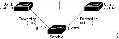
Note![]() You would never enter an offset value of 1 because that is the offset number of the primary edge port itself.
You would never enter an offset value of 1 because that is the offset number of the primary edge port itself.
If you have configured a preempt delay time by entering the rep preempt delay seconds interface configuration command and a link failure and recovery occurs, VLAN load balancing begins after the configured preemption time period elapses without another link failure. The alternate port specified in the load-balancing configuration blocks the configured VLANs and unblocks all other segment ports. If the primary edge port cannot determine the alternate port for VLAN balancing, the default action is no preemption.
Each port in a segment has a unique port ID. The port ID format is similar to the one used by the spanning tree algorithm: a port number (unique on the bridge) associated to a MAC address (unique in the network). To determine the port ID of a port, enter the show interface interface-id rep detail privileged EXEC command.
There is no limit to the number of times that you can enter the rep block port id port-id vlan vlan-list interface configuration command. You can block an unlimited number, range, or sequence of VLANs.
When you use the rep block port id port-id vlan vlan-list interface configuration command on a REP primary edge port to block a VLAN list and then use the same command to block another VLAN list on the same port, the second VLAN list does not replace the first VLAN list but is appended to the first VLAN list.
When you use the rep block port id port-id vlan vlan-list interface configuration command on a REP primary edge port to block a VLAN list on one port and then use the same command to block another VLAN list on another port, the original port number and VLAN list are overwritten.
Examples
The following example shows how to configure REP VLAN load balancing on the Switch B primary edge port (Gigabit Ethernet port 0/1) and to configure Gigabit Ethernet port 1/1 of Switch A as the alternate port to block VLANs 1 to 100. The alternate port is identified by its port ID, shown in bold in the output of the show interface rep detail command for the Switch A port.
The following example shows how to configure VLAN load balancing by using a neighbor offset number and how to verify the configuration by entering the show interfaces rep detail privileged EXEC command:
Related Commands
rep lsl-age-timer
Use the rep lsl-age-timer interface configuration command on a Resilient Ethernet Protocol (REP) port to configure the Link Status Layer (LSL) age timer for the time period that the REP interface remains up without receiving a hello from the REP neighbor. Use the no form of this command to return to the default time.
Syntax Description
The age-out time in milliseconds. The range is from 120 to 10000 ms in 40-ms increments. The default is 5000 ms (5 seconds). |
Command Default
The REP link shuts down if it does not receive a hello message from a neighbor within 5000 ms.
Command Modes
Command History
|
|
|
|---|---|
Usage Guidelines
The LSL hello timer is set to the age-timer value divided by 3 so that there should be at least two LSL hellos sent during the LSL age-timer period. If no hellos are received within that time, the REP link shuts down.
In Cisco IOS Release 12.2(52)SE, the LSL age-timer range changed from 3000 to 10000 ms in 500-ms increments to 120 to 10000 ms in 40-ms increments. If the REP neighbor device is not running Cisco IOS Release 12.2(52)SE or later, you must use the shorter time range because the device does not accept values out of the earlier range.
EtherChannel port channel interfaces do not support LSL age-timer values less than 1000 ms. If you try to configure a value less than 1000 ms on a port channel, you receive an error message and the command is rejected.
Examples
The following example shows how to configure the REP LSL age timer on a REP link to 7000 ms:
You can verify the configured ageout time by entering the show interfaces rep detail privileged EXEC command.
Related Commands
|
|
|
|---|---|
Displays REP configuration and status for all interfaces or the specified interface, including the configured LSL age-out timer value. |
rep preempt delay
Use the rep preempt delay interface configuration command on the REP primary edge port to configure a waiting period after a segment port failure and recovery before Resilient Ethernet Protocol (REP) VLAN load balancing is triggered. Use the no form of this command to remove the configured delay.
Syntax Description
Set the number of seconds to delay REP preemption. The range is 15 to 300. |
Command Default
No preemption delay is set. If you do not enter the rep preempt delay command, the default is manual preemption with no delay.
Command Modes
Command History
|
|
|
|---|---|
Usage Guidelines
You must enter this command on the REP primary edge port.
You must enter this command and configure a preempt time delay if you want VLAN load balancing to automatically trigger after a link failure and recovery.
If VLAN load balancing is configured, after a segment port failure and recovery, the REP primary edge port starts a delay timer before VLAN load balancing occurs. Note that the timer restarts after each link failure. When the timer expires, the REP primary edge alerts the alternate port to perform VLAN load balancing (configured by using the rep block port interface configuration command) and prepares the segment for the new topology. The configured VLAN list is blocked at the alternate port, and all other VLANs are blocked at the primary edge port.
Do not configure VLAN load balancing on an interface that carries Ethernet over multiprotocol label switching (EoMPLS) traffic. VLAN load balancing across the REP ring might cause some of the EoMPLS traffic to not be forwarded.
Examples
The following example shows how to configure REP preemption time delay of 100 seconds on the primary edge port:
You can verify your settings by entering the show interfaces rep privileged EXEC command.
Related Commands
|
|
|
|---|---|
Displays REP configuration and status for all interfaces or the specified interface. |
rep preempt segment
Use the rep preempt segment privileged EXEC command to manually start Resilient Ethernet Protocol (REP) VLAN load balancing on a segment.
rep preempt segment segment_id
Syntax Description
Command Default
Command Modes
Command History
|
|
|
|---|---|
Usage Guidelines
When you enter the rep preempt segment segment-id command, a confirmation message appears before the command is executed because preemption can cause network disruption.
Enter this command on the switch on the segment that has the primary edge port.
If you do not configure VLAN load balancing, entering this command results in the default behavior—the primary edge port blocks all VLANs.
You configure VLAN load balancing by entering the rep block port { id port-id | neighbor_offset | preferred } vlan { vlan-list | all } interface configuration command on the REP primary edge port before you manually start preemption.
Examples
The following example shows how to manually trigger REP preemption on segment 100 with the confirmation message:
Related Commands
|
|
|
|---|---|
Displays REP configuration and status for all interfaces or the specified interface. |
rep segment
Use the rep segment interface configuration command to enable Resilient Ethernet Protocol (REP) on the interface and to assign a segment ID to it. Use the no form of this command to disable REP on the interface.
rep segment segment-id [ edge [ no-neighbor ] [ primary ]] [ preferred ]
Syntax Description
Command Default
REP is disabled on the interface.
When REP is enabled on an interface, the default is for the port to be a regular segment port.
Command Modes
Command History
|
|
|
|---|---|
Usage Guidelines
REP ports must be Layer 2 trunk ports. A non-ES REP port can be either an IEEE 802.1Q trunk port or an ISL trunk port.
REP ports should not be configured as one of these port types:
You must configure two edge ports on each REP segment, a primary edge port and a port to act as a secondary edge port. If you configure two ports in a segment as the primary edge port, for example ports on different switches, the configuration is allowed, but the REP selects one of them to serve as the segment primary edge port.
REP is supported on EtherChannels, but not on an individual port that belongs to an EtherChannel.
–![]() There is no limit to the number of REP ports on a switch; however, only two ports on a switch can belong to the same REP segment.
There is no limit to the number of REP ports on a switch; however, only two ports on a switch can belong to the same REP segment.
–![]() If only one port on a switch is configured in a segment, the port should be an edge port.
If only one port on a switch is configured in a segment, the port should be an edge port.
–![]() If two ports on a switch belong to the same segment, they must be both edge ports, both regular segment ports, or one regular port and one edge no-neighbor port. An edge port and regular segment port on a switch cannot belong to the same segment.
If two ports on a switch belong to the same segment, they must be both edge ports, both regular segment ports, or one regular port and one edge no-neighbor port. An edge port and regular segment port on a switch cannot belong to the same segment.
–![]() If two ports on a switch belong to the same segment and one is configured as an edge port and one as a regular segment port (a misconfiguration), the edge port is treated as a regular segment port.
If two ports on a switch belong to the same segment and one is configured as an edge port and one as a regular segment port (a misconfiguration), the edge port is treated as a regular segment port.
If you configure two ports in a segment as the primary edge port, for example ports on different switches, the REP selects one of them to serve as the segment primary edge port. Enter the show rep topology privileged EXEC command on a port in the segment to verify which port is the segment primary edge port.
REP interfaces come up in a blocked state and remain in a blocked state until notified that it is safe to unblock. You need to be aware of this to avoid sudden connection losses.
You should configure REP only in networks with redundancy. Configuring REP in a network without redundancy causes loss of connectivity.
In networks where ports on a neighboring switch do not support REP, you can configure the non-REP facing ports as edge no-neighbor ports. These ports inherit all properties of edge ports and you can configure them as any other edge port, including to send STP or REP topology change notices to the aggregation switch. In this case, the STP topology change notice (TCN) that is sent is a multiple spanning-tree (MST) STP message.
Examples
The following example shows how to enable REP on a regular (nonedge) segment port:
The following example shows how to enable REP on a port and identify the port as the REP primary edge port:
The following example shows how to configure the same configuration when the interface has no external REP neighbor:
The following example shows how to enable REP on a port and identify the port as the REP secondary edge port:
You can verify your settings by entering the show interfaces rep privileged EXEC command. To verify which port in the segment is the primary edge port, enter the show rep topology privileged EXEC command.
Related Commands
rep stcn
Use the rep stcn interface configuration command on a Resilient Ethernet Protocol (REP) edge port to configure the port to send REP segment topology change notifications (STCNs) to another interface, to other segments, or to Spanning Tree Protocol (STP) networks. Use the no form of this command to disable the sending of STCNs to the interface, segment, or STP network.
rep stcn { interface interface-id | segment id-list | stp }
no rep stcn { interface | segment | stp }
Syntax Description
Command Default
Transmission of STCNs to other interfaces, segments, or STP networks is disabled.
Command Modes
Command History
|
|
|
|---|---|
Usage Guidelines
Enter this command on a segment edge port.
You use this command to notify other portions of the Layer 2 network of topology changes that occur in the local REP segment. This removes obsolete entries in the Layer 2 forwarding table in other parts of the network, which allows faster network convergence.
Examples
The following example shows how to configure a REP edge port to send STCNs to segments 25 to 50:
You can verify your settings by entering the show interfaces rep detail privileged EXEC command.
Related Commands
|
|
|
|---|---|
Displays REP configuration and status for all interfaces or the specified interface. |
reset
To leave the proposed new VLAN database but remain in VLAN configuration mode and reset the proposed new database to be identical to the VLAN database currently implemented, use the reset command.
Syntax Description
Command Default
Command Modes
Command History
|
|
|
|---|---|
This command was introduced on the Catalyst 4500 series switch. |
Examples
The following example shows how to reset the proposed new VLAN database to the current VLAN database:
Switch(vlan-config)# reset
RESET completed.
Switch(vlan-config)#
revision
To set the MST configuration revision number, use the revision command. To return to the default settings, use the no form of this command.
Syntax Description
Configuration revision number; valid values are from 0 to 65535. |
Command Default
Command Modes
Command History
|
|
|
|---|---|
This command was introduced on the Catalyst 4500 series switch. |
Usage Guidelines
If two Catalyst 4500 series switches have the same configuration but have different configuration revision numbers, they are considered to be part of two different regions.
Examples
The following example shows how to set the configuration revision number:
Related Commands
|
|
|
|---|---|
sampler (netflow-lite monitor submode)
Note![]() NetFlow-lite is supported only on Catalyst 4948E and Catalyst 4948E-F Ethernet switches.
NetFlow-lite is supported only on Catalyst 4948E and Catalyst 4948E-F Ethernet switches.
To activate sampling on an interface in netflow-lite monitor submode, use the sampler command. To delete a sampler, use the no form of this command.
Syntax Description
Command Default
Command Modes
Command History
|
|
|
|---|---|
This command was introduced on the Catalyst 4500 series switch. |
Usage Guidelines
You can enter this command under the physical port interface mode, port channel interface, or config VLAN mode.
Examples
The following example shows how to configure a monitor on a port interface Gigabit 1/3:
You can verify your settings with the show netflow-lite sampler privileged EXEC command.
Related Commands
|
|
|
|---|---|
service
The service command creates a configuration template for all instance-service instantiations of that particular service.
[no] service {ipv4 | ipv6 | ethernet }
Syntax Description
Enables Layer 3 network services for the IPv4 Address family. |
|
Enables Layer 3 network services for the IPv6 Address family. |
|
Command Default
Command Modes
Command History
|
|
|
Usage Guidelines
The service command creates a service instance under the instance-id and enters the instance-service mode.
You cannot configure service ethernet for the same instance where service ipv4 or service ipv6 is configured.
Examples
The following example shows how to enable the service ipv4 mode:
service-policy (interface configuration)
To attach a policy map to an interface or to apply different QoS policies on VLANs that an interface belongs to, use the service-policy command. To remove a policy map from an interface, use the no form of this command.
service-policy { input | output } policy-map name
no service-policy { input | output } policy-map name
Syntax Description
Command Default
Command Modes
Command History
|
|
|
|---|---|
This command was introduced on the Catalyst 4500 series switch. |
|
Support for applying different QoS policies on VLANs was introduced. |
Usage Guidelines
Layer 2 interfaces can be part of multiple VLANs (for example, a typical trunk port). In conjunction with the vlan-range command, you can use the service-policy command to specify different QoS policies on different VLANs.
Note![]() This capability is restricted to Layer 2 interfaces.
This capability is restricted to Layer 2 interfaces.
You can apply a service policy under an interface as well as a VLAN range at the same time. However, this is allowed only when the interface policy has only queuing actions whereas a VLAN has only non-queueing actions (QoS marking and/or policing) actions.
To attach a service policy to a VLAN, the VLAN configuration mode has to be used.
Examples
The following example shows how to attach a policy map to Fast Ethernet interface 5/20:
The following example shows how to apply policy map p1 for traffic in VLANs 20 and 400, and policy map p2 for traffic in VLANs 300 through 301:
The following example shows how to attach a policy map to a VLAN using a Supervisor Engine 6-E:
Switch#
Related Commands
service-policy (policy-map class)
To create a service policy that is a quality of service (QoS) policy within a policy map (called a hierarchical service policy), use the service-policy policy-map class configuration command. To disable the service policy within a policy map, use the no form of this command.
service-policy policy-map-name
no service-policy policy-map-name
Syntax Description
Command Default
Command Modes
Policy-map class configuration mode
Command History
|
|
|
|---|---|
This command was introduced on the Catalyst 4500 series switch. |
|
Added support for Supervisor Engine 6-E and Catalyst 4900M chassis. |
Usage Guidelines
Use the service-policy command only in a hierarchical policy map attached to a physical port. This command is valid in policy maps at level two of the hierarchy.
You can create a hierarchy by having the parent policy map specify marking and/or policing actions and having the child policy map specify the queueing actions.
If you enter this command in policy-map class configuration mode, you return to policy-map configuration mode by using the exit command. To return to privileged EXEC mode, use the end command.
Examples
The following example shows how to create a hierarchical service policy in the service policy called “parent ” :
You can verify your settings by entering the show policy-map privileged EXEC command.
Related Commands
service-policy input (control-plane)
To attach a policy map to a control plane for aggregate control plane services, use the service-policy input command. Use the no form of this command to remove a service policy from a control plane.
service-policy input policy-map-name
Syntax Description
Applies the specified service policy to the packets that are entering the control plane. |
|
Name of a service policy map (created using the policy-map command) to be attached. |
Command Default
Command Modes
Control-plane configuration mode
Command History
|
|
|
|---|---|
This command was introduced on the Catalyst 4500 series switch. |
Usage Guidelines
In this release, the only policy-map accepted on the control-plane is system-cpp-policy. It is already attached to the control-plane at start up. If not (due to some error conditions), it is recommended to use the global macro system-cpp command to attach it to the control-plane. The system-cpp-policy created by the system contains system predefined classes. For these predefined classes, you can change the policing parameters but you should not make any other change to the classes.
You can define your own class-maps and append them to the end of the system-cpp-policy policy-map.
Examples
The following example shows how to configure trusted hosts with source addresses 10.1.1.1 and 10.1.1.2 to forward Telnet packets to the control plane without constraint, while allowing all remaining Telnet packets to be policed at the specified rate:
10.1.1.2 trusted host traffic.
Related Commands
session module
Note![]() This command is only supported in SSO mode and does not work in RPR mode.
This command is only supported in SSO mode and does not work in RPR mode.
To log in to the standby supervisor engine using a virtual console, use the session module configuration command.
Syntax Description
Command Default
Command Modes
Command History
|
|
|
|---|---|
This command was introduced on the Catalyst 4500 series switch. |
Usage Guidelines
Catalyst 4500 series switches can be configured with two supervisor engines to provide redundancy. When the switch is powered, one of the supervisor engines becomes active and remains active until a switchover occurs. The other supervisor engine remains in standby mode.
Each supervisor engine has its own console port. Access to the standby supervisor engine is possible only through the console port of the standby supervisor engine. Therefore, you must connect to the standby console to access, monitor or debug the standby supervisor.
The virtual console for the standby supervisor engine enables you to access the standby console from the active supervisor engine without requiring a physical connection to the standby console. It uses IPC over EOBC to communicate with the standby supervisor engine and emulates the standby console on the active supervisor engine. Only one active standby console session is active at any time.
The virtual console for the standby supervisor engine allows users who are logged onto the active supervisor engine to remotely execute show commands on the standby supervisor engine and view the results on the active supervisor engine. Virtual console is available only from the active supervisor engine.
You can access the standby virtual console from the active supervisor engine with the attach module, session module, or remote login commands on the active supervisor engine. You must be in privilege EXEC mode (level 15) to run these commands to access the standby console.
Note![]() The session module command is identical to the attach module mod and the remote login module mod commands.
The session module command is identical to the attach module mod and the remote login module mod commands.
Once you enter the standby virtual console, the terminal prompt automatically changes to hostname-standby-console#, where hostname is the configured name of the switch. The prompt is restored back to the original prompt when you exit the virtual console.
You exit the virtual console with the exit or quit commands. When the inactivity period of the terminal on the active supervisor engine where you logged in exceeds the configured idle time, you are automatically logged out of the terminal on the active supervisor engine. In such a case, the virtual console session is also terminated. Virtual console session is also automatically terminated when the standby is rebooted. After the standby boots up, you need to create another virtual console session.
The following limitations apply to the standby virtual console:
- All commands on the virtual console run to completion. It does not provide the auto-more feature; it behaves as if the terminal length 0 command has been executed. It is also non-interactive. Therefore, a running command cannot be interrupted or aborted by any key sequence on the active supervisor engine. If a command produces considerable output, the virtual console displays it on the supervisor screen.
- The virtual console is non-interactive. Because the virtual console does not detect the interactive nature of a command, any command that requires user interaction causes the virtual console to wait until the RPC timer aborts the command.
- The virtual console timer is set to 60 seconds. The virtual console returns to its prompt after 60 seconds. During this time, you cannot abort the command from the keyboard. You must wait for the timer to expire before you continue.
- You cannot use virtual console to view debug and syslog messages that are being displayed on the standby supervisor engine. The virtual console only displays the output of commands that are executed from the virtual console. Other information that is displayed on the real standby console does not appear on the virtual console.
Examples
To log in to the standby supervisor engine using a virtual console, do the following:
If the standby console is not enabled, the following message appears:
Related Commands
|
|
|
|---|---|
set
To mark IP traffic by setting a class of service (CoS), a Differentiated Services Code Point (DSCP), or IP-precedence in the packet, use the set policy-map class configuration command. To remove the traffic classification, use the no form of this command.
set { cos new-cos | [ ip ] { dscp new-dscp | precedence new-precedence } | qos group value }
no set cos new-cos | ip { dscp new-dscp | precedence new-precedence } | qos group value }
Syntax Description
Command Default
Command Modes
Policy-map class configuration mode
Command History
|
|
|
|---|---|
This command was introduced on the Catalyst 4500 series switch. |
|
Added support for Supervisor Engine 6-E and Catalyst 4900M chassis. |
Usage Guidelines
You can use the set command only in class-level classes.
The set dscp new-dscp and the set precedence new-precedence commands are the same as the set ip dscp new-dscp and the set ip precedence new-precedence commands.
For the set dscp new-dscp or the set precedence new-precedence command, you can enter a mnemonic name for a commonly used value. For example, you can enter the set dscp af11 command, which is the as same entering the set dscp 10 command. You can enter the set precedence critical command, which is the same as entering the set precedence 5 command. For a list of supported mnemonics, enter the set dscp ? or the set precedence ? command to see the command-line help strings.
You can configure the set cos new-cos , set dscp new-dscp , or set precedence new-precedence command in an ingress and an e gress policy map attached to an interface or VLAN.
To return to policy-map configuration mode, use the exit command. To return to privileged EXEC mode, use the end command.
Examples
The following example shows how to create a policy map called p1 with CoS values assigned to different traffic types. Class maps for voice and video-data have already been created.
You can verify your settings by entering the show policy-map privileged EXEC command.
Related Commands
set cos
To set the Layer 2 class of service (CoS) value of a packet, use the set cos command in policy-map class configuration mode. To remove a specific CoS value setting, use the no form of this command.
set cos { cos-value | from-field [ table table-map-name ]}
no set cos { cos-value | from-field [ table table-map-name ]}
Syntax Description
Command Default
Command Modes
Policy-map class configuration mode
Command History
|
|
|
|---|---|
This command was introduced on Supervisor Engine 6E and Catalyst 4900M. |
Usage Guidelines
The set cos command can be used in an ingress as well as an egress policy map attached to an interface or VLAN.
You can use this command to specify the “from-field” packet-marking category to be used for mapping and setting the CoS value. The “from-field” packet-marking categories are as follows:
- Precedence
- Differentiated services code point (DSCP)
- Cost of Service (CoS)
- Quality of Service (QoS) group
If you specify a “from-field” category but do not specify the table keyword and the applicable table-map-nam e argument, the default action will be to copy the value associated with the “from-field” category as the CoS value. For instance, if you configure the set cos precedence command, the precedence value will be copied and used as the CoS value.
You can do the same for the DSCP marking category. That is, you can configure the set cos dscp command, and the DSCP value will be copied and used as the CoS value.
Note![]() If you configure the set cos dscp command, only the first three bits (the class selector bits) of the DSCP field are used.
If you configure the set cos dscp command, only the first three bits (the class selector bits) of the DSCP field are used.
Note![]() If you configure the set cos qos group command, only the three least significant bits of the qos group field are used.
If you configure the set cos qos group command, only the three least significant bits of the qos group field are used.
Examples
The following example shows how to configure a policy map called cos-set and assign different CoS values for different types of traffic. This example assumes that the class maps called voice and video-data have already been created.
policy-map cos-setSwitch(config-pmap)#
class voiceSwitch(config-pmap-c)#
set cos 1Switch(config-pmap-c)#
exitSwitch(config-pmap)#
class video-dataSwitch(config-pmap-c)#
set cos 2Switch(config-pmap-c)#
end
The following example shows how to configure a policy map called policy-cos and to use the values defined in a table map called table-map1. The table map called table-map1 was created earlier with the table-map (value mapping) command. For more information about the table-map (value mapping) command, see the table-map (value mapping) command page.
The following example shows how the setting of the CoS value is based on the precedence value defined in table-map1:
policy-map policy-cosSwitch(config-pmap)#
class class-defaultSwitch(config-pmap-c)#
set cos precedence table table-map1
end
Related Commands
set dscp
To mark a packet by setting the differentiated services code point (DSCP) value in the type of service (ToS) byte, use the set dscp command in policy-map class configuration mode. To remove a previously set DSCP value, use the no form of this command.
set [ ip ] dscp { dscp-value | from-field [ table table-map-name ]}
no set [ ip ] dscp { dscp-value | from-field [ table table-map-name ]
Syntax Description
Command Default
Command Modes
Policy-map class configuration mode
Command History
|
|
|
|---|---|
This command was introduced on the Catalyst 4500 series switch. |
|
Added support for from-field on Supervisor Engine 6-E and Catalyst 4900M. |
Usage Guidelines
Once the DSCP bit is set, other quality of service (QoS) features can then operate on the bit settings.
DSCP and Precedence Values Are Mutually Exclusive
The set dscp command cannot be used with the set precedence command to mark the same packet. The two values, DSCP and precedence, are mutually exclusive. A packet can have one value or the other, but not both.
You can use this command to specify the “from-field” packet-marking category to be used for mapping and setting the DSCP value. The “from-field” packet-marking categories are as follows:
If you specify a “from-field” category but do not specify the table keyword and the applicable table-map-nam e argument, the default action will be to copy the value associated with the “from-field” category as the DSCP value. For instance, if you configure the set dscp cos command, the CoS value will be copied and used as the DSCP value.
Note![]() The CoS field is a three-bit field, and the DSCP field is a six-bit field. If you configure the set dscp cos command, only the three bits of the CoS field will be used.
The CoS field is a three-bit field, and the DSCP field is a six-bit field. If you configure the set dscp cos command, only the three bits of the CoS field will be used.
If you configure the set dscp qos-group command, the QoS group value will be copied and used as the DSCP value.
The valid value range for the DSCP is a number from 0 to 63. The valid value range for the QoS group is a number from 0 to 63.
Set DSCP Values in IPv6 Environments
When this command is used in IPv6 environments, the default match occurs on both IP and IPv6 packets. However, the actual packets set by this function are only those which meet the match criteria of the class-map containing this function.
Set DSCP Values for IPv6 Packets Only
To set DSCP values for IPv6 values only, the match protocol ipv6 command must also be used. Without that command, the DSCP match defaults to match both IPv4 and IPv6 packets.
Set DSCP Values for IPv4 Packets Only
To set DSCP values for IPv4 packets only, use the ip keyword in the match command for classification. Without the ip keyword, the match occurs on both IPv4 and IPv6 packets.
Examples
Packet-marking Values and Table Map
In the following example, the policy map called policy1 is created to use the packet-marking values defined in a table map called table-map1. The table map was created earlier with the table-map (value mapping) command. For more information about the table-map (value mapping) command, see the table-map (value mapping) command page.
The following example shows how the DSCP value is set according to the CoS value defined in the table map called table-map1.
policy-map policy1Switch(config-pmap)#
class class-defaultSwitch(config-pmap-c)#
set dscp cos table table-map1
end
Related Commands
set ip next-hop verify-availability
To configure policy routing to verify the reachability of the next hop of a route map before the device performs policy routing to that next hop, use the set ip next-hop verify-availability command in route-map configuration mode. To disable this function, use the no form of this command.
set ip next-hop verify-availability [ next-hop-address sequence track object ]
no set ip next-hop verify-availability [ next-hop-address sequence track object ]
Syntax Description
Command Default
The reachability of the next hop of a route map before the device performs policy routing, is not verified.
Command Modes
Route-map configuration (config-route-map)
Command History
|
|
|
|---|---|
Usage Guidelines
The set ip next-hop verify-availability command can be used with policy-based routing (PBR) to verify next hop reachability to support object tracking using Internet Control Message Protocol (ICMP) ping to verify if a remote device is reachable.
Examples
The following example shows you how to verify the next-hop IP address in a route map:
Related Commands
|
|
|
|---|---|
Displays information about objects that are tracked by the tracking process. |
|
Tracks the state of an interface, an ip route, or a response time reporter. |
set precedence
To set the precedence value in the packet header, use the set precedence command in policy-map class configuration mode. To remove the precedence value, use the no form of this command.
set precedence { precedence-value | from-field [ table table-map-name ]}
no set precedence { precedence-value | from-field [ table table-map-name ]}
Syntax Description
Command Default
Command Modes
Policy-map class configuration mode
Command History
|
|
|
|---|---|
This command was introduced on the Catalyst 4500 series switch. |
|
Added support for from-field on Supervisor Engine 6-E and Catalyst 4900M. |
Usage Guidelines
The set precedence command cannot be used with the set dscp command to mark the same packet. The two values, DSCP and precedence, are mutually exclusive. A packet can be one value or the other, but not both.
You can use this command to specify the “from-field” packet-marking category to be used for mapping and setting the precedence value. The “from-field” packet-marking categories are as follows:
If you specify a “from-field” category but do not specify the table keyword and the applicable table-map-nam e argument, the default action will be to copy the value associated with the “from-field” category as the precedence value. For instance, if you configure the set precedence cos command, the CoS value will be copied and used as the precedence value.
You can do the same for the QoS group-marking category. That is, you can configure the set precedence qos-group command, and the QoS group value will be copied and used as the precedence value.
The valid value range for the precedence value is a number from 0 to 7. The valid value range for the QoS group is a number from 0 to 63. Therefore, when configuring the set precedence qos-group command the three least significant bits of qos-group are copied to precedence.
Precedence Values in IPv6 Environments
When this command is used in IPv6 environments it can set the value in both IPv4 and IPv6 packets. However, the actual packets set by this function are only those that meet the match criteria of the class-map containing this function.
Setting Precedence Values for IPv6 Packets Only
To set the precedence values for IPv6 packets only, the match protocol ipv6 command must also be used in the class-map that classified packets for this action. Without the match protocol ipv6 command, the class-map may classify both IPv6 and IPv4 packets, (depending on other match criteria) and the set precedence command will act upon both types of packets.
Setting Precedence Values for IPv4 Packets Only
To set the precedence values for IPv4 packets only, use a command involving the ip keyword like the match ip precedence or match ip dscp command or include the match protocol ip command along with the others in the class map. Without the additional ip keyword, the class-map may match both IPv6 and IPv4 packets (depending on the other match criteria) and the set precedence or set dscp command may act upon both types of packets.
Examples
In the following example, the policy map named policy-cos is created to use the values defined in a table map named table-map1. The table map named table-map1 was created earlier with the table-map (value mapping) command. For more information about the table-map (value mapping) command, see the table-map (value mapping) command page.
The following example shows how the precedence value is set according to the CoS value defined in table-map1.
policy-map policy-cosSwitch(config-pmap)#
class class-defaultSwitch(config-pmap-c)#
set precedence cos table table-map1
end
Related Commands
set qos-group
To set a quality of service (QoS) group identifier (ID) that can be used later to classify packets, use the set qos-group command in policy-map class configuration mode. To remove the group ID, use the no form of this command.
Syntax Description
Command Default
Command Modes
Policy-map class configuration mode
Command History
|
|
|
|---|---|
This command was introduced on the Catalyst 4500 series switch using a Supervisor Engine 6-E and Catalyst 4900M chassis. |
Usage Guidelines
The set qos-group command allows you to associate a group ID with a packet. This association is made through a service-policy attached to an interface or VLAN in the input direction. The group ID can be later used in the output direction to apply QoS service policies to the packet.
Examples
The following example shows how to set the qos-group to 5:
Related Commands
shape (class-based queueing)
To enable traffic shaping a class of traffic in a policy map attached to a physical port, use the shape average policy-map class command. Traffic shaping limits the data transmission rate. To return to the default setting, use the no form of this command.
shape average { rate } [ bps | kbps | mbps | gbps ]
shape average percent { percent_value }
Syntax Description
Command Default
Command Modes
Policy-map class configuration mode
Command History
|
|
|
|---|---|
Usage Guidelines
Use the shape command only in a policy map attached to a physical port. This command is valid in policy maps at any level of the hierarchy.
Shaping is the process of delaying out-of-profile packets in queues so that they conform to a specified profile. Shaping is distinct from policing. Policing drops packets that exceed a configured threshold, but shaping buffers packets so that traffic remains within the threshold. Shaping offers greater smoothness in handling traffic than policing.
You cannot use the bandwidth , dbl , and the shape policy-map class configuration commands with the priority policy-map class configuration command in the same class within the same policy map. However, you can use these commands in the same policy map.
To return to policy-map configuration mode, use the exit command. To return to privileged EXEC mode, use the end command.
Examples
The following example shows how to limit the specified traffic class to a data transmission rate of 256 kbps:
You can verify your settings by entering the show policy-map privileged EXEC command.
Related Commands
shape (interface configuration)
To specify traffic shaping on an interface, use the shape command. To remove traffic shaping, use the no form of this command
Syntax Description
Command Default
Command Modes
Interface transmit queue configuration mode
Command History
|
|
|
This command was introduced on the Catalyst 4500 series switch. |
Usage Guidelines
This command is not supported on Supervisor Engine 6-E, Supervisor Engine 6L-E, Catalyst 4900M, Catalyst 4948E, and Catalyst 4948E-F.
Traffic shaping is available on all the ports, and it sets an upper limit on the bandwidth.
When the high shape rates are configured on the Catalyst 4500 the Catalyst 4500 Supervisor Engine V (WS-X4516) and the Catalyst 4500 Supervisor Engine V-10GE (WS-X4516-10GE), the shaped traffic rate may not be achieved in situations that involve contention and unusual packet size distributions. On the ports that are multiplexed through a Stub ASIC and connected to the backplane gigaports, the shape rates above 7 Mbps may not be achieved under worst-case conditions. On ports that are connected directly to the backplane gigaports, or the supervisor engine gigaports, the shape rates above 50 Mbps may not be achieved under worst-case conditions.
Some examples of ports that are connected directly to the backplane are as follows:
- Uplink ports on Supervisor Engine V and V-10GE
- Ports on the WS-X4306-GB module
- The two 1000BASE-X ports on the WS-X4232-GB-RJ module
- The first two ports on the WS-X4418-GB module
- The two 1000BASE-X ports on the WS-X4412-2GB-TX module
All ports on the 24-port modules and the 48-port modules are multiplexed through a Stub ASIC. Some examples of ports multiplexed through a Stub ASIC are as follows:
Examples
The following example shows how to configure a maximum bandwidth (70 percent) for the interface fa3/1:
shell trigger
Use the shell trigger global configuration command to create a user defined trigger. Use the no form of this command to delete the trigger.
shell trigger identifier description
no shell trigger identifier description
Syntax Description
Specifies the event trigger identifier. The identifier should have no spaces or hyphens between words. |
|
Command Default
Command Modes
Command History
|
|
|
|---|---|
This command was introduced on the Catalyst 4500 series switch. |
Usage Guidelines
Use this command to create user-defined event triggers in conjunction with the macro auto execute global configuration command.
To support dynamic device discovery when using 802.1X authentication, configure the RADIUS authentication server to support the Cisco attribute-value (AV) pair: auto-smart-port=event trigger.
This command is mainly used for 802.1X authentication based triggers provided 802.1X or MAB is supported, enabling you to map new platform strings or device IDs to their respective macros or functions.
Examples
The following example shows how to create a user-defined event trigger called RADIUS_MAB_EVENT:
Related Commands
|
|
|
|---|---|
use-petr
To configure a router to use an IPv4 or IPv6 Locator/ID Separation Protocol (LISP) Proxy Egress Tunnel Router (PETR), use the use-petr command in LISP Instance configuration mode or LISP Instance Service configuration mode. To remove the use of a LISP PETR, use the no form of this command.
[no] use-petr locator-address [priority priority weight weight ]
Syntax Description
Command Default
Command Modes
LISP Instance (router-lisp-instance)
LISP Instance Service (router-lisp-instance-service)
Command History
|
|
|
|---|---|
Usage Guidelines
Use the use-petr command to enable an Ingress Tunnel Router (ITR) or Proxy Ingress Tunnel Router (PITR)
to use IPv4 or IPv6 Proxy Egress Tunnel Router (PETR) services. When the use of PETR services is enabled,.instead of natively forwarding LISP endpoint identifier (EID) (source) packets destined to non-LISP sites, these packets are LISP-encapsulated and forwarded to the PETR. Upon receiving these packets, the PETR decapsulates them and then forwards them natively toward the non-LISP destination.
Do not use use-petr command in Service-Ethernet configuration mode.
PETR services may be necessary in several cases:
1. By default when a LISP site forwards packets to a non-LISP site natively (not LISP encapsulated), source IP address of the packet is that of an EID. When the provider side of the access network is configured with strict unicast reverse path forwarding (uRPF) or an anti-spoofing access list, it may consider these packets to be spoofed and drop them since EIDs are not advertised in the provider core network. In this case, instead of natively forwarding packets destined to non-LISP sites, the ITR encapsulates these packet using its site locator(s) as the source address and the PETR as the destination address.
2. When a LISP IPv6 (EID) site needs to connect to a non-LISP IPv6 site and the ITR locators or some portion of the intermediate network does not support IPv6 (it is IPv4 only), the PETR can be used to traverse (hop over) the address family incompatibility, assuming that the PETR has both IPv4 and IPv6 connectivity. The ITR in this case can LISP-encapsulate the IPv6 EIDs with IPv4 locators destined for the PETR, which de-encapsulates the packets and forwards them natively to the non-LISP IPv6 site over its IPv6 connection. In this case, the use of the PETR effectively allows the LISP site packets to traverse the IPv4 portion of network using the LISP mixed protocol encapsulation support.
Examples
The following example configures an ITR to use two PETRs: one has an IPv4 locator of 10.1.1.1 and is configured as the primary PETR (priority 1 weight 100), and the other has an IPv4 locator of 10.1.2.1 and is
configured as the secondary PETR (priority 2 weight 100). In this case, LISP site IPv4 EIDs destined to non-LISP IPv4 sites will be encapsulated in an IPv4 LISP header to the primary PETR located at 10.1.1.1 unless it fails, in which case the secondary will be used.
 Feedback