- Preface
- Product Overview
- Command-Line Interfaces
- Configuring the Switch for the First Time
- Administering the Switch
- Configuring the Cisco IOS In Service Software Upgrade Process
- Configuring Interfaces
- Checking Port Status and Connectivity
- Configuring Supervisor Engine Redundancy Using RPR and SSO
- Configuring Cisco NSF with SSO Supervisor Engine Redundancy
- Environmental Monitoring and Power Management
- Configuring Power over Ethernet
- Configuring the Catalyst 4500 Series Switch with Cisco Network Assistant
- Configuring VLANs, VTP, and VMPS
- Configuring IP Unnumbered Interface
- Configuring Layer 2 Ethernet Interfaces
- Configuring SmartPort Macros
- Configuring STP and MST
- Configuring Flex Links and Flex Links+
- Configuring Resilient Ethernet Protocol
- Configuring Optional STP Features
- Configuring EtherChannel
- Configuring IGMP Snooping and Filtering
- Configuring IPv6 MLD Snooping
- Configuring 802.1Q and Layer 2 Protocol Tunneling
- Configuring CDP
- Configuring LLDP
- Configuring UDLD
- Configuring Unidirectional Ethernet
- Configuring Layer 3 Interfaces
- Configuring Cisco Express Forwarding
- Configuring Unicast Reverse Path Forwarding
- Configuring IP Multicast
- Configuring Policy-Based Routing
- Configuring VRF-lite
- Configuring Quality of Service
- Configuring Voice Interfaces
- Configuring Private VLANs
- Configuring 802.1X Port-Based Authentication
- Configuring Port Security
- Configuring Control Plane Policing
- Configuring DHCP Snooping, IP Source Guard, and IPSG for Static Hosts
- Configuring Dynamic ARP Inspection
- Configuring Network Security with ACLs
- Port Unicast and Multicast Flood Blocking
- Configuring Storm Control
- Configuring SPAN and RSPAN
- Configuring System Message Logging
- Configuring SNMP
- Configuring NetFlow
- Configuring Cisco IP SLA
- Configuring RMON
- Performing Diagnostics
- Configuring WCCP Version 2 Services
- ROM Monitor
- Configuring MIB Support
- Configuring CFM and OAM
- Configuring Y.1731
- Acronym
- Index
Catalyst 4500 Series Switch Software Configuration Guide, 12.2(46)SG
Bias-Free Language
The documentation set for this product strives to use bias-free language. For the purposes of this documentation set, bias-free is defined as language that does not imply discrimination based on age, disability, gender, racial identity, ethnic identity, sexual orientation, socioeconomic status, and intersectionality. Exceptions may be present in the documentation due to language that is hardcoded in the user interfaces of the product software, language used based on RFP documentation, or language that is used by a referenced third-party product. Learn more about how Cisco is using Inclusive Language.
- Updated:
- March 21, 2015
Chapter: Configuring VRF-lite
Configuring VRF-lite
Virtual Private Networks (VPNs) provide a secure way for customers to share bandwidth over an ISP backbone network. A VPN is a collection of sites sharing a common routing table. A customer site is connected to the service provider network by one or more interfaces, and the service provider associates each interface with a VPN routing table. A VPN routing table is called a VPN routing/forwarding (VRF) table.
With the VRF-lite feature, the Catalyst 4500 series switch supports multiple VPN routing/forwarding instances in customer edge devices. (VRF-lite is also termed multi-VRF CE, or multi-VRF Customer Edge Device). VRF-lite allows a service provider to support two or more VPNs with overlapping IP addresses using one interface.

Note ![]() The switch does not use Multiprotocol Label Switching (MPLS) to support VPNs. For information about MPLS VRF, refer to the Cisco IOS Switching Services Configuration Guide at
The switch does not use Multiprotocol Label Switching (MPLS) to support VPNs. For information about MPLS VRF, refer to the Cisco IOS Switching Services Configuration Guide at
: http://www.cisco.com/en/US/docs/ios/mpls/configuration/guide/mp_vpn_ipv4_ipv6_ps6922_TSD_Products_Configuration_Guide_Chapter.html
This chapter includes these topics:
•![]() Default VRF-lite Configuration
Default VRF-lite Configuration
•![]() VRF-lite Configuration Guidelines
VRF-lite Configuration Guidelines
•![]() Configuring a VPN Routing Session
Configuring a VPN Routing Session
•![]() Configuring BGP PE to CE Routing Sessions
Configuring BGP PE to CE Routing Sessions
•![]() VRF-lite Configuration Example
VRF-lite Configuration Example
Note ![]() For complete syntax and usage information for the switch commands used in this chapter, first look at the Cisco Catalyst 4500 Series Switch Command Reference and related publications at this location:
For complete syntax and usage information for the switch commands used in this chapter, first look at the Cisco Catalyst 4500 Series Switch Command Reference and related publications at this location:
http://www.cisco.com/en/US/products//hw/switches/ps4324/index.html
If the command is not found inthe Catalyst 4500 Command Reference, it will be found in the larger Cisco IOS library. Refer to the Catalyst 4500 Series Switch Cisco IOS Command Reference and related publications at this location:
http://www.cisco.com/en/US/products/ps6350/index.html
Understanding VRF-lite
VRF-lite is a feature that enables a service provider to support two or more VPNs, where IP addresses can be overlapped among the VPNs. VRF-lite uses input interfaces to distinguish routes for different VPNs and forms virtual packet-forwarding tables by associating one or more Layer 3 interfaces with each VRF. Interfaces in a VRF can be either physical, such as Ethernet ports, or logical, such as VLAN SVIs, but a Layer 3 interface cannot belong to more than one VRF at any time.
Note ![]() VRF-lite interfaces must be Layer 3 interfaces.
VRF-lite interfaces must be Layer 3 interfaces.
VRF-lite includes these devices:
•![]() Customer edge (CE) devices provide customer access to the service provider network over a data link to one or more provider edge routers. The CE device advertises the site's local routes to the provider edge router and learns the remote VPN routes from it. A Catalyst 4500 series switch can be a CE.
Customer edge (CE) devices provide customer access to the service provider network over a data link to one or more provider edge routers. The CE device advertises the site's local routes to the provider edge router and learns the remote VPN routes from it. A Catalyst 4500 series switch can be a CE.
•![]() Provider edge (PE) routers exchange routing information with CE devices by using static routing or a routing protocol such as BGP, RIPv1, or RIPv2.
Provider edge (PE) routers exchange routing information with CE devices by using static routing or a routing protocol such as BGP, RIPv1, or RIPv2.
•![]() The PE is only required to maintain VPN routes for those VPNs to which it is directly attached, eliminating the need for the PE to maintain all of the service provider VPN routes. Each PE router maintains a VRF for each of its directly connected sites. Multiple interfaces on a PE router can be associated with a single VRF if all of these sites participate in the same VPN. Each VPN is mapped to a specified VRF. After learning local VPN routes from CEs, a PE router exchanges VPN routing information with other PE routers by using internal BGP (IBPG).
The PE is only required to maintain VPN routes for those VPNs to which it is directly attached, eliminating the need for the PE to maintain all of the service provider VPN routes. Each PE router maintains a VRF for each of its directly connected sites. Multiple interfaces on a PE router can be associated with a single VRF if all of these sites participate in the same VPN. Each VPN is mapped to a specified VRF. After learning local VPN routes from CEs, a PE router exchanges VPN routing information with other PE routers by using internal BGP (IBPG).
•![]() Provider routers (or core routers) are any routers in the service provider network that do not attach to CE devices.
Provider routers (or core routers) are any routers in the service provider network that do not attach to CE devices.
With VRF-lite, multiple customers can share one CE, and only one physical link is used between the CE and the PE. The shared CE maintains separate VRF tables for each customer and switches or routes packets for each customer based on its own routing table. VRF-lite extends limited PE functionality to a CE device, giving it the ability to maintain separate VRF tables to extend the privacy and security of a VPN to the branch office.
Figure 34-1 shows a configuration where each Catalyst 4500 series switch acts as multiple virtual CEs. Because VRF-lite is a Layer 3 feature, each interface in a VRF must be a Layer 3 interface.
Figure 34-1 Catalyst 4500 Series Switches Acting as Multiple Virtual CEs
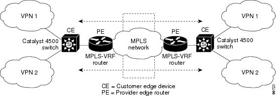
This is the packet-forwarding process in a VRF-lite CE-enabled network as shown in Figure 34-1:
•![]() When the CE receives a packet from a VPN, it looks up the routing table based on the input interface. When a route is found, the CE forwards the packet to the PE.
When the CE receives a packet from a VPN, it looks up the routing table based on the input interface. When a route is found, the CE forwards the packet to the PE.
•![]() When the ingress PE receives a packet from the CE, it performs a VRF lookup. When a route is found, the router adds a corresponding MPLS label to the packet and sends it to the MPLS network.
When the ingress PE receives a packet from the CE, it performs a VRF lookup. When a route is found, the router adds a corresponding MPLS label to the packet and sends it to the MPLS network.
•![]() When an egress PE receives a packet from the network, it strips the label and uses the label to identify the correct VPN routing table. Then the egress PE performs the normal route lookup. When a route is found, it forwards the packet to the correct adjacency.
When an egress PE receives a packet from the network, it strips the label and uses the label to identify the correct VPN routing table. Then the egress PE performs the normal route lookup. When a route is found, it forwards the packet to the correct adjacency.
•![]() When a CE receives a packet from an egress PE, it uses the input interface to look up the correct VPN routing table. If a route is found, the CE forwards the packet within the VPN.
When a CE receives a packet from an egress PE, it uses the input interface to look up the correct VPN routing table. If a route is found, the CE forwards the packet within the VPN.
To configure VRF, create a VRF table and specify the Layer 3 interface associated with the VRF. Then configure the routing protocols in the VPN and between the CE and the PE. BGP is the preferred routing protocol used to distribute VPN routing information across the provider's backbone. The VRF-lite network has three major components:
•![]() VPN route target communities—Lists of all other members of a VPN community. You need to configure VPN route targets for each VPN community member.
VPN route target communities—Lists of all other members of a VPN community. You need to configure VPN route targets for each VPN community member.
•![]() Multiprotocol BGP peering of VPN community PE routers—Propagates VRF reachability information to all members of a VPN community. You need to configure BGP peering in all PE routers within a VPN community.
Multiprotocol BGP peering of VPN community PE routers—Propagates VRF reachability information to all members of a VPN community. You need to configure BGP peering in all PE routers within a VPN community.
•![]() VPN forwarding—Transports all traffic between all VPN community members across a VPN service-provider network.
VPN forwarding—Transports all traffic between all VPN community members across a VPN service-provider network.
Default VRF-lite Configuration
Table 34-1 shows the default VRF configuration.
VRF-lite Configuration Guidelines
Consider these points when configuring VRF in your network:
•![]() A switch with VRF-lite is shared by multiple customers, and all customers have their own routing tables.
A switch with VRF-lite is shared by multiple customers, and all customers have their own routing tables.
•![]() Because customers use different VRF tables, the same IP addresses can be reused. Overlapped IP addresses are allowed in different VPNs.
Because customers use different VRF tables, the same IP addresses can be reused. Overlapped IP addresses are allowed in different VPNs.
•![]() VRF-lite lets multiple customers share the same physical link between the PE and the CE. Trunk ports with multiple VLANs separate packets among customers. All customers have their own VLANs.
VRF-lite lets multiple customers share the same physical link between the PE and the CE. Trunk ports with multiple VLANs separate packets among customers. All customers have their own VLANs.
•![]() VRF-lite does not support all MPLS-VRF functionality: label exchange, LDP adjacency, or labeled packets.
VRF-lite does not support all MPLS-VRF functionality: label exchange, LDP adjacency, or labeled packets.
•![]() For the PE router, there is no difference between using VRF-lite or using multiple CEs. In Figure 34-1, multiple virtual Layer 3 interfaces are connected to the VRF-lite device.
For the PE router, there is no difference between using VRF-lite or using multiple CEs. In Figure 34-1, multiple virtual Layer 3 interfaces are connected to the VRF-lite device.
•![]() The Catalyst 4500 series switch supports configuring VRF by using physical ports, VLAN SVIs, or a combination of both. The SVIs can be connected through an access port or a trunk port.
The Catalyst 4500 series switch supports configuring VRF by using physical ports, VLAN SVIs, or a combination of both. The SVIs can be connected through an access port or a trunk port.
•![]() A customer can use multiple VLANs as long as they do not overlap with those of other customers. A customer's VLANs are mapped to a specific routing table ID that is used to identify the appropriate routing tables stored on the switch.
A customer can use multiple VLANs as long as they do not overlap with those of other customers. A customer's VLANs are mapped to a specific routing table ID that is used to identify the appropriate routing tables stored on the switch.
•![]() The Layer 3 TCAM resource is shared between all VRFs. To ensure that any one VRF has sufficient CAM space, use the maximum routes command.
The Layer 3 TCAM resource is shared between all VRFs. To ensure that any one VRF has sufficient CAM space, use the maximum routes command.
•![]() A Catalyst 4500 series switch using VRF can support one global network and up to 64 VRFs. The total number of routes supported is limited by the size of the TCAM.
A Catalyst 4500 series switch using VRF can support one global network and up to 64 VRFs. The total number of routes supported is limited by the size of the TCAM.
•![]() Most routing protocols (BGP, OSPF, EIGRP, RIP and static routing) can be used between the CE and the PE. However, we recommend using external BGP (EBGP) for these reasons:
Most routing protocols (BGP, OSPF, EIGRP, RIP and static routing) can be used between the CE and the PE. However, we recommend using external BGP (EBGP) for these reasons:
–![]() BGP does not require multiple algorithms to communicate with multiple CEs.
BGP does not require multiple algorithms to communicate with multiple CEs.
–![]() BGP is designed for passing routing information between systems run by different administrations.
BGP is designed for passing routing information between systems run by different administrations.
–![]() BGP makes it easy to pass attributes of the routes to the CE.
BGP makes it easy to pass attributes of the routes to the CE.
•![]() VRF-lite does not support IGRP and ISIS.
VRF-lite does not support IGRP and ISIS.
•![]() VRF-lite does not affect the packet switching rate.
VRF-lite does not affect the packet switching rate.
•![]() Multicast cannot be configured on the same Layer 3 interface at the same time.
Multicast cannot be configured on the same Layer 3 interface at the same time.
•![]() The capability vrf-lite subcommand under router ospf should be used when configuring OSPF as the routing protocol between the PE and the CE.
The capability vrf-lite subcommand under router ospf should be used when configuring OSPF as the routing protocol between the PE and the CE.
Configuring VRFs
To configure one or more VRFs, perform this task:
Note ![]() For complete syntax and usage information for the commands, refer to the switch command reference for this release and the Cisco IOS Switching Services Command Reference for Release 12.2.
For complete syntax and usage information for the commands, refer to the switch command reference for this release and the Cisco IOS Switching Services Command Reference for Release 12.2.
Use the no ip vrf vrf-name global configuration command to delete a VRF and to remove all interfaces from it. Use the no ip vrf forwarding interface configuration command to remove an interface from the VRF.
Configuring a VPN Routing Session
Routing within the VPN can be configured with any supported routing protocol (RIP, OSPF, or BGP) or with static routing. The configuration shown here is for OSPF, but the process is the same for other protocols.
To configure OSPF in the VPN, perform this task:
Use the no router ospf process-id vrf vrf-name global configuration command to disassociate the VPN forwarding table from the OSPF routing process.
Configuring BGP PE to CE Routing Sessions
To configure a BGP PE to CE routing session, perform this task:
Use the no router bgp autonomous-system-number global configuration command to delete the BGP routing process. Use the command with keywords to delete routing characteristics.
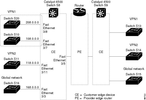
VRF-lite Configuration Example
Figure 34-2 is a simplified example of the physical connections in a network similar to that in Figure 34-1. OSPF is the protocol used in VPN1, VPN2, and the global network. BGP is used in the CE to PE connections. The example commands show how to configure the CE switch S8 and include the VRF configuration for switches S20 and S11 and the PE router commands related to traffic with switch S8. Commands for configuring the other switches are not included but would be similar.
Figure 34-2 VRF-lite Configuration Example
Configuring Switch S8
On switch S8, enable routing and configure VRF.
Switch# configure terminal
Enter configuration commands, one per line. End with CNTL/Z.
Switch(config)# ip routing
Switch(config)# ip vrf v11
Switch(config-vrf)# rd 800:1
Switch(config-vrf)# route-target export 800:1
Switch(config-vrf)# route-target import 800:1
Switch(config-vrf)# exit
Switch(config)# ip vrf v12
Switch(config-vrf)# rd 800:2
Switch(config-vrf)# route-target export 800:2
Switch(config-vrf)# route-target import 800:2
Switch(config-vrf)# exit
Configure the loopback and physical interfaces on switch S8. Fast Ethernet interface 3/5 is a trunk connection to the PE. Interfaces 3/7 and 3/11 connect to VPNs:
Switch(config)# interface loopback1
Switch(config-if)# ip vrf forwarding v11
Switch(config-if)# ip address 8.8.1.8 255.255.255.0
Switch(config-if)# exit
Switch(config)# interface loopback2
Switch(config-if)# ip vrf forwarding v12
Switch(config-if)# ip address 8.8.2.8 255.255.255.0
Switch(config-if)# exit
Switch(config)# interface FastEthernet3/5
Switch(config-if)# switchport trunk encapsulation dot1q
Switch(config-if)# switchport mode trunk
Switch(config-if)# no ip address
Switch(config-if)# exit
Switch(config)# interface FastEthernet3/8
Switch(config-if)# switchport access vlan 208
Switch(config-if)# no ip address
Switch(config-if)# exit
Switch(config)# interface FastEthernet3/11
Switch(config-if)# switchport trunk encapsulation dot1q
Switch(config-if)# switchport mode trunk
Switch(config-if)# no ip address
Switch(config-if)# exit
Configure the VLANs used on switch S8. VLAN 10 is used by VRF 11 between the CE and the PE. VLAN 20 is used by VRF 12 between the CE and the PE. VLANs 118 and 208 are used for VRF for the VPNs that include switch S11 and switch S20, respectively:
Switch(config)# interface Vlan10
Switch(config-if)# ip vrf forwarding v11
Switch(config-if)# ip address 38.0.0.8 255.255.255.0
Switch(config-if)# exit
Switch(config)# interface Vlan20
Switch(config-if)# ip vrf forwarding v12
Switch(config-if)# ip address 83.0.0.8 255.255.255.0
Switch(config-if)# exit
Switch(config)# interface Vlan118
Switch(config-if)# ip vrf forwarding v12
Switch(config-if)# ip address 118.0.0.8 255.255.255.0
Switch(config-if)# exit
Switch(config)# interface Vlan208
Switch(config-if)# ip vrf forwarding v11
Switch(config-if)# ip address 208.0.0.8 255.255.255.0
Switch(config-if)# exit
Configure OSPF routing in VPN1 and VPN2:
Switch(config)# router ospf 1 vrf vl1
Switch(config-router)# redistribute bgp 800 subnets
Switch(config-router)# network 208.0.0.0 0.0.0.255 area 0
Switch(config-router)# exit
Switch(config)# router ospf 2 vrf vl2
Switch(config-router)# redistribute bgp 800 subnets
Switch(config-router)# network 118.0.0.0 0.0.0.255 area 0
Switch(config-router)# exit
Configure BGP for CE to PE routing:
Switch(config)# router bgp 800
Switch(config-router)# address-family ipv4 vrf vl2
Switch(config-router-af)# redistribute ospf 2 match internal
Switch(config-router-af)# neighbor 83.0.0.3 remote-as 100
Switch(config-router-af)# neighbor 83.0.0.3 activate
Switch(config-router-af)# network 8.8.2.0 mask 255.255.255.0
Switch(config-router-af)# exit
Switch(config-router)# address-family ipv4 vrf vl1
Switch(config-router-af)# redistribute ospf 1 match internal
Switch(config-router-af)# neighbor 38.0.0.3 remote-as 100
Switch(config-router-af)# neighbor 38.0.0.3 activate
Switch(config-router-af)# network 8.8.1.0 mask 255.255.255.0
Switch(config-router-af)# end
Configuring Switch S20
Configure S20 to connect to CE:
Switch# configure terminal
Enter configuration commands, one per line. End with CNTL/Z.
Switch(config)# ip routing
Switch(config)# interface Fast Ethernet 0/7
Switch(config-if)# no switchport
Switch(config-if)# ip address 208.0.0.20 255.255.255.0
Switch(config-if)# exit
Switch(config)# router ospf 101
Switch(config-router)# network 208.0.0.0 0.0.0.255 area 0
Switch(config-router)# end
Configuring Switch S11
Configure S11 to connect to CE:
Switch# configure terminal
Enter configuration commands, one per line. End with CNTL/Z.
Switch(config)# ip routing
Switch(config)# interface Gigabit Ethernet 0/3
Switch(config-if)# switchport trunk encapsulation dot1q
Switch(config-if)# switchport mode trunk
Switch(config-if)# no ip address
Switch(config-if)# exit
Switch(config)# interface Vlan118
Switch(config-if)# ip address 118.0.0.11 255.255.255.0
Switch(config-if)# exit
Switch(config)# router ospf 101
Switch(config-router)# network 118.0.0.0 0.0.0.255 area 0
Switch(config-router)# end
Configuring the PE Switch S3
On switch S3 (the router), these commands configure only the connections to switch S8:
Router# configure terminal
Enter configuration commands, one per line. End with CNTL/Z.
Router(config)# ip vrf v1
Router(config-vrf)# rd 100:1
Router(config-vrf)# route-target export 100:1
Router(config-vrf)# route-target import 100:1
Router(config-vrf)# exit
Router(config)# ip vrf v2
Router(config-vrf)# rd 100:2
Router(config-vrf)# route-target export 100:2
Router(config-vrf)# route-target import 100:2
Router(config-vrf)# exit
Router(config)# ip cef
Router(config)# interface Loopback1
Router(config-if)# ip vrf forwarding v1
Router(config-if)# ip address 3.3.1.3 255.255.255.0
Router(config-if)# exit
Router(config)# interface Loopback2
Router(config-if)# ip vrf forwarding v2
Router(config-if)# ip address 3.3.2.3 255.255.255.0
Router(config-if)# exit
Router(config)# interface Fast Ethernet3/0.10
Router(config-if)# encapsulation dot1q 10
Router(config-if)# ip vrf forwarding v1
Router(config-if)# ip address 38.0.0.3 255.255.255.0
Router(config-if)# exit
Router(config)# interface Fast Ethernet3/0.20
Router(config-if)# encapsulation dot1q 20
Router(config-if)# ip vrf forwarding v2
Router(config-if)# ip address 83.0.0.3 255.255.255.0
Router(config-if)# exit
Router(config)# router bgp 100
Router(config-router)# address-family ipv4 vrf v2
Router(config-router-af)# neighbor 83.0.0.8 remote-as 800
Router(config-router-af)# neighbor 83.0.0.8 activate
Router(config-router-af)# network 3.3.2.0 mask 255.255.255.0
Router(config-router-af)# exit
Router(config-router)# address-family ipv4 vrf vl
Router(config-router-af)# neighbor 83.0.0.8 remote-as 800
Router(config-router-af)# neighbor 83.0.0.8 activate
Router(config-router-af)# network 3.3.1.0 mask 255.255.255.0
Router(config-router-af)# end
Displaying VRF-lite Status
To display information about VRF-lite configuration and status, perform one of the following tasks:
Note ![]() For more information about the information in the displays, refer to the Cisco IOS Switching Services Command Reference at: http://www.cisco.com/en/US/docs/ios/ipswitch/command/reference/isw_book.html
For more information about the information in the displays, refer to the Cisco IOS Switching Services Command Reference at: http://www.cisco.com/en/US/docs/ios/ipswitch/command/reference/isw_book.html
 Feedback