- Index
- Preface
- Overview
- Using the Command-Line Interface
- Getting Started with CMS
- Assigning the Switch IP Address and Default Gateway
- Managing Switch Stacks
- Clustering Switches
- Administering the Switch
- Configuring 802.1X Port-Based Authentication
- Configuring Interface Characteristics
- Configuring VLANs
- Configuring VTP
- Configuring Voice VLAN
- Configuring STP
- Configuring Optional Spanning-Tree Features
- Configuring IGMP Snooping and MVR
- Configuring Port-Based Traffic Control
- Configuring CDP
- Configuring UDLD
- Configuring SPAN and RSPAN
- Configuring RMON
- Configuring System Message Logging
- Configuring SNMP
- Configuring Network Security with ACLs
- Configuring QoS
- Configuring EtherChannels
- Configuring IP Unicast Routing
- Configuring HSRP
- Configuring IP Multicast Routing
- Configuring MSDP
- Configuring Fallback Bridging
- Troubleshooting
- Supported MIBs
- Working with the IOS File System, Configuration Files, and Software Images
- Unsupported Commands for Release 12.1(11)AX
Catalyst 3750 Switch Software Configuration Guide, 12.1(11)AX
Bias-Free Language
The documentation set for this product strives to use bias-free language. For the purposes of this documentation set, bias-free is defined as language that does not imply discrimination based on age, disability, gender, racial identity, ethnic identity, sexual orientation, socioeconomic status, and intersectionality. Exceptions may be present in the documentation due to language that is hardcoded in the user interfaces of the product software, language used based on RFP documentation, or language that is used by a referenced third-party product. Learn more about how Cisco is using Inclusive Language.
- Updated:
- August 3, 2007
Chapter: Overview
Overview
This chapter provides these topics about the Catalyst 3750 switch software:
•![]() Default Settings After Initial Switch Configuration
Default Settings After Initial Switch Configuration
•![]() Network Configuration Examples
Network Configuration Examples
Unless otherwise noted, the term switch refers to a standalone switch and to a switch stack.
Features
The Catalyst 3750 switches are shipped with either of these software images installed:
•![]() Standard multilayer software image (SMI), which provides Layer 2+ features (enterprise-class intelligent services). These features include access control lists (ACLs), quality of service (QoS), static routing, and the Hot Standby Router Protocol (HSRP) and Routing Information Protocol (RIP). Switches with the SMI installed can be upgraded to the EMI.
Standard multilayer software image (SMI), which provides Layer 2+ features (enterprise-class intelligent services). These features include access control lists (ACLs), quality of service (QoS), static routing, and the Hot Standby Router Protocol (HSRP) and Routing Information Protocol (RIP). Switches with the SMI installed can be upgraded to the EMI.
•![]() Enhanced multilayer software image (EMI), which provides a richer set of enterprise-class intelligent services. It includes all SMI features plus full Layer 3 routing (IP unicast routing, IP multicast routing, and fallback bridging). To distinguish it from the Layer 2+ static routing and RIP, the EMI includes protocols such as the Enhanced Interior Gateway Routing Protocol (EIGRP) and Open Shortest Path First (OSPF) Protocol.
Enhanced multilayer software image (EMI), which provides a richer set of enterprise-class intelligent services. It includes all SMI features plus full Layer 3 routing (IP unicast routing, IP multicast routing, and fallback bridging). To distinguish it from the Layer 2+ static routing and RIP, the EMI includes protocols such as the Enhanced Interior Gateway Routing Protocol (EIGRP) and Open Shortest Path First (OSPF) Protocol.

Note ![]() Unless otherwise noted, all features described in this chapter and in this guide are supported on both SMI and EMI.
Unless otherwise noted, all features described in this chapter and in this guide are supported on both SMI and EMI.
The Catalyst 3750 switches have these features:
•![]() Ease-of-Use and Ease-of-Deployment Features
Ease-of-Use and Ease-of-Deployment Features
•![]() Quality of Service (QoS) and Class of Service (CoS) Features
Quality of Service (QoS) and Class of Service (CoS) Features
Ease-of-Use and Ease-of-Deployment Features
•![]() Cluster Management Suite (CMS) graphical user interface (GUI) for
Cluster Management Suite (CMS) graphical user interface (GUI) for
–![]() Simplifying and minimizing switch, switch stack, and switch cluster management through a supported web browser from anywhere in your intranet.
Simplifying and minimizing switch, switch stack, and switch cluster management through a supported web browser from anywhere in your intranet.
–![]() Accomplishing multiple configuration tasks from a single CMS window without needing to remember command-line interface (CLI) commands to accomplish specific tasks.
Accomplishing multiple configuration tasks from a single CMS window without needing to remember command-line interface (CLI) commands to accomplish specific tasks.
–![]() Interactive guide mode that guides you in configuring complex features such as VLANs, access control lists (ACLs), and quality of service (QoS).
Interactive guide mode that guides you in configuring complex features such as VLANs, access control lists (ACLs), and quality of service (QoS).
–![]() Automated configuration wizards that prompt you to provide only the minimum required information to configure complex features such as QoS priorities for video traffic, priority levels for data applications, and security.
Automated configuration wizards that prompt you to provide only the minimum required information to configure complex features such as QoS priorities for video traffic, priority levels for data applications, and security.
–![]() Applying actions to multiple ports and multiple switches at the same time, such as VLAN and QoS settings, inventory and statistic reports, link- and switch-level monitoring and troubleshooting, and multiple switch software upgrades.
Applying actions to multiple ports and multiple switches at the same time, such as VLAN and QoS settings, inventory and statistic reports, link- and switch-level monitoring and troubleshooting, and multiple switch software upgrades.
–![]() Viewing a topology of interconnected devices to identify existing switch clusters and eligible switches that can join a cluster and to identify link information between switches.
Viewing a topology of interconnected devices to identify existing switch clusters and eligible switches that can join a cluster and to identify link information between switches.
–![]() Monitoring real-time status of a switch or multiple switches from the LEDs on the front-panel images. The system, redundant power system (RPS), and port LED colors on the images are similar to those used on the physical LEDs.
Monitoring real-time status of a switch or multiple switches from the LEDs on the front-panel images. The system, redundant power system (RPS), and port LED colors on the images are similar to those used on the physical LEDs.
•![]() Cisco StackWise technology for
Cisco StackWise technology for
–![]() Connecting up to nine switches through their StackWise ports and operating as a single switch or switch-router in the network.
Connecting up to nine switches through their StackWise ports and operating as a single switch or switch-router in the network.
–![]() Creating a bidirectional 32-Gbps switching fabric across the switch stack, where all stack members have full access to the system bandwidth.
Creating a bidirectional 32-Gbps switching fabric across the switch stack, where all stack members have full access to the system bandwidth.
–![]() Using a single IP address and configuration file to manage the entire switch stack.
Using a single IP address and configuration file to manage the entire switch stack.
–![]() Automatic IOS version-check of new stack members with the option to automatically load images from the stack master or from a Trivial File Transfer Protocol (TFTP) server.
Automatic IOS version-check of new stack members with the option to automatically load images from the stack master or from a Trivial File Transfer Protocol (TFTP) server.
–![]() Adding, removing, and replacing switches in the stack without disrupting the operation of the stack.
Adding, removing, and replacing switches in the stack without disrupting the operation of the stack.
•![]() Switch clustering technology for
Switch clustering technology for
–![]() Unified configuration, monitoring, authentication, and software upgrade of multiple, cluster-capable switches, regardless of their geographic proximity and interconnection media, including Ethernet, Fast Ethernet, Fast EtherChannel, small-form pluggable (SFP) modules, Gigabit Ethernet, and Gigabit EtherChannel connections. Refer to the release notes for a list of cluster-capable switches.
Unified configuration, monitoring, authentication, and software upgrade of multiple, cluster-capable switches, regardless of their geographic proximity and interconnection media, including Ethernet, Fast Ethernet, Fast EtherChannel, small-form pluggable (SFP) modules, Gigabit Ethernet, and Gigabit EtherChannel connections. Refer to the release notes for a list of cluster-capable switches.
–![]() Automatic discovery of candidate switches and creation of clusters of up to 16 switches that can be managed through a single IP address.
Automatic discovery of candidate switches and creation of clusters of up to 16 switches that can be managed through a single IP address.
–![]() Extended discovery of cluster candidates that are not directly connected to the command switch.
Extended discovery of cluster candidates that are not directly connected to the command switch.
Performance Features
•![]() Autosensing of port speed and autonegotiation of duplex mode on all switch ports for optimizing bandwidth
Autosensing of port speed and autonegotiation of duplex mode on all switch ports for optimizing bandwidth
•![]() IEEE 802.3X flow control on all ports (the switch does not send pause frames)
IEEE 802.3X flow control on all ports (the switch does not send pause frames)
•![]() Up to 32 Gbps of forwarding rates in a switch stack
Up to 32 Gbps of forwarding rates in a switch stack
•![]() EtherChannel for enhanced fault tolerance and for providing up to 8 Gbps (Gigabit EtherChannel) or 800 Mbps (Fast EtherChannel) full duplex of bandwidth between switches, routers, and servers
EtherChannel for enhanced fault tolerance and for providing up to 8 Gbps (Gigabit EtherChannel) or 800 Mbps (Fast EtherChannel) full duplex of bandwidth between switches, routers, and servers
•![]() Port Aggregation Protocol (PAgP) for automatic creation of EtherChannel links
Port Aggregation Protocol (PAgP) for automatic creation of EtherChannel links
•![]() Forwarding of Layer 2 and Layer 3 packets at Gigabit line rate across the switches in the stack
Forwarding of Layer 2 and Layer 3 packets at Gigabit line rate across the switches in the stack
•![]() Per-port storm control for preventing broadcast, multicast, and unicast storms
Per-port storm control for preventing broadcast, multicast, and unicast storms
•![]() Port blocking on forwarding unknown Layer 2 unknown unicast, multicast, and bridged broadcast traffic
Port blocking on forwarding unknown Layer 2 unknown unicast, multicast, and bridged broadcast traffic
•![]() Cisco Group Management Protocol (CGMP) server support and Internet Group Management Protocol (IGMP) snooping for IGMP versions 1 and 2:
Cisco Group Management Protocol (CGMP) server support and Internet Group Management Protocol (IGMP) snooping for IGMP versions 1 and 2:
–![]() (For CGMP devices) CGMP for limiting multicast traffic to specified end stations and reducing overall network traffic
(For CGMP devices) CGMP for limiting multicast traffic to specified end stations and reducing overall network traffic
–![]() (For IGMP devices) IGMP snooping for efficiently forwarding multimedia and multicast traffic
(For IGMP devices) IGMP snooping for efficiently forwarding multimedia and multicast traffic
•![]() Multicast VLAN registration (MVR) to continuously send multicast streams in a multicast VLAN while isolating the streams from subscriber VLANs for bandwidth and security reasons
Multicast VLAN registration (MVR) to continuously send multicast streams in a multicast VLAN while isolating the streams from subscriber VLANs for bandwidth and security reasons
•![]() IGMP filtering for controlling the set of multicast groups to which hosts on a switch port can belong
IGMP filtering for controlling the set of multicast groups to which hosts on a switch port can belong
•![]() Switch Database Management (SDM) templates for allocating system resources to maximize support for user-selected features
Switch Database Management (SDM) templates for allocating system resources to maximize support for user-selected features
Management Options
•![]() CMS—CMS is a graphical user interface that can be launched from anywhere in your network through a web browser such as Netscape Communicator or Microsoft Internet Explorer. CMS is already installed on the switch. For more information about CMS, see "Getting Started with CMS."
CMS—CMS is a graphical user interface that can be launched from anywhere in your network through a web browser such as Netscape Communicator or Microsoft Internet Explorer. CMS is already installed on the switch. For more information about CMS, see "Getting Started with CMS."
•![]() CLI—The switch IOS command-line interface software is enhanced to support desktop- and multilayer-switching features. You can access the CLI either by connecting your management station directly to the switch console port or by using Telnet from a remote management station. You can manage the switch stack by connecting to the console port of any stack member. For more information about the CLI, see "Using the Command-Line Interface."
CLI—The switch IOS command-line interface software is enhanced to support desktop- and multilayer-switching features. You can access the CLI either by connecting your management station directly to the switch console port or by using Telnet from a remote management station. You can manage the switch stack by connecting to the console port of any stack member. For more information about the CLI, see "Using the Command-Line Interface."
•![]() SNMP—You can use Simple Network Management Protocol (SNMP) management applications such as CiscoWorks2000 LAN Management Suite (LMS) and HP OpenView. You can manage from an SNMP-compatible management station that is running platforms such as HP OpenView or SunNet Manager. The switch supports a comprehensive set of MIB extensions and four remote monitoring (RMON) groups. For more information about using SNMP, see "Configuring SNMP."
SNMP—You can use Simple Network Management Protocol (SNMP) management applications such as CiscoWorks2000 LAN Management Suite (LMS) and HP OpenView. You can manage from an SNMP-compatible management station that is running platforms such as HP OpenView or SunNet Manager. The switch supports a comprehensive set of MIB extensions and four remote monitoring (RMON) groups. For more information about using SNMP, see "Configuring SNMP."
Manageability Features
•![]() Dynamic Host Configuration Protocol (DHCP) for automating configuration of switch information (such as IP address, default gateway, host name, and Domain Name System [DNS] and Trivial File Transfer Protocol [TFTP] server names)
Dynamic Host Configuration Protocol (DHCP) for automating configuration of switch information (such as IP address, default gateway, host name, and Domain Name System [DNS] and Trivial File Transfer Protocol [TFTP] server names)
•![]() Directed unicast requests to a DNS server for identifying a switch through its IP address and its corresponding host name and to a TFTP server for administering software upgrades from a TFTP server
Directed unicast requests to a DNS server for identifying a switch through its IP address and its corresponding host name and to a TFTP server for administering software upgrades from a TFTP server
•![]() Address Resolution Protocol (ARP) for identifying a switch through its IP address and its corresponding Media Access Control (MAC) address
Address Resolution Protocol (ARP) for identifying a switch through its IP address and its corresponding Media Access Control (MAC) address
•![]() Cisco Discovery Protocol (CDP) versions 1 and 2 for network topology discovery and mapping between the switch and other Cisco devices on the network
Cisco Discovery Protocol (CDP) versions 1 and 2 for network topology discovery and mapping between the switch and other Cisco devices on the network
•![]() Network Time Protocol (NTP) for providing a consistent timestamp to all switches from an external source
Network Time Protocol (NTP) for providing a consistent timestamp to all switches from an external source
•![]() Cisco IOS File System (IFS) for providing a single interface to all file systems that the switch uses
Cisco IOS File System (IFS) for providing a single interface to all file systems that the switch uses
•![]() In-band management access through CMS over a Netscape Communicator or Microsoft Internet Explorer browser session
In-band management access through CMS over a Netscape Communicator or Microsoft Internet Explorer browser session
•![]() In-band management access through up to 16 simultaneous Telnet connections for multiple command-line interface (CLI)-based sessions over the network
In-band management access through up to 16 simultaneous Telnet connections for multiple command-line interface (CLI)-based sessions over the network
•![]() In-band management access through Simple Network Management Protocol (SNMP) versions 1 and 2c get and set requests
In-band management access through Simple Network Management Protocol (SNMP) versions 1 and 2c get and set requests
•![]() Out-of-band management access through the switch console port to a directly attached terminal or to a remote terminal through a serial connection or a modem
Out-of-band management access through the switch console port to a directly attached terminal or to a remote terminal through a serial connection or a modem
Note ![]() For additional descriptions of the management interfaces, see the "Network Configuration Examples" section.
For additional descriptions of the management interfaces, see the "Network Configuration Examples" section.
Availability Features
•![]() Hot Standby Router Protocol (HSRP) for command switch and Layer 3 router redundancy
Hot Standby Router Protocol (HSRP) for command switch and Layer 3 router redundancy
•![]() Automatic stack master re-election for replacing stack masters that become unavailable (failover support)
Automatic stack master re-election for replacing stack masters that become unavailable (failover support)
The newly elected stack master begins accepting Layer 2 traffic in less than 1 second and Layer 3 traffic between 3 to 5 seconds.
•![]() Cross-stack EtherChannel for providing redundant links across the switch stack
Cross-stack EtherChannel for providing redundant links across the switch stack
•![]() UniDirectional Link Detection (UDLD) and aggressive UDLD for detecting and disabling unidirectional links on fiber-optic interfaces caused by incorrect fiber-optic wiring or port faults
UniDirectional Link Detection (UDLD) and aggressive UDLD for detecting and disabling unidirectional links on fiber-optic interfaces caused by incorrect fiber-optic wiring or port faults
•![]() IEEE 802.1D Spanning Tree Protocol (STP) for redundant backbone connections and loop-free networks. STP has these features:
IEEE 802.1D Spanning Tree Protocol (STP) for redundant backbone connections and loop-free networks. STP has these features:
–![]() Up to 128 spanning-tree instances supported
Up to 128 spanning-tree instances supported
–![]() Per-VLAN Spanning Tree (PVST) for balancing load across VLANs
Per-VLAN Spanning Tree (PVST) for balancing load across VLANs
–![]() UplinkFast, cross-stack UplinkFast, and BackboneFast for fast convergence after a spanning-tree topology change and for achieving load balancing between redundant uplinks, including Gigabit uplinks and cross-stack Gigabit uplinks
UplinkFast, cross-stack UplinkFast, and BackboneFast for fast convergence after a spanning-tree topology change and for achieving load balancing between redundant uplinks, including Gigabit uplinks and cross-stack Gigabit uplinks
•![]() Optional spanning-tree features available in PVST mode:
Optional spanning-tree features available in PVST mode:
–![]() Port Fast for eliminating the forwarding delay by enabling a port to immediately transition from the blocking state to the forwarding state
Port Fast for eliminating the forwarding delay by enabling a port to immediately transition from the blocking state to the forwarding state
–![]() BPDU guard for shutting down Port Fast-enabled ports that receive BPDUs
BPDU guard for shutting down Port Fast-enabled ports that receive BPDUs
–![]() Root guard for preventing switches outside the network core from becoming the spanning-tree root
Root guard for preventing switches outside the network core from becoming the spanning-tree root
•![]() Equal-cost routing for link-level and switch-level redundancy
Equal-cost routing for link-level and switch-level redundancy
•![]() Redundant power system (RPS) support through the Cisco RPS 300 and Cisco RPS 675 for enhancing power reliability
Redundant power system (RPS) support through the Cisco RPS 300 and Cisco RPS 675 for enhancing power reliability
VLAN Features
•![]() Support for up to 1005 VLANs for assigning users to VLANs associated with appropriate network resources, traffic patterns, and bandwidth
Support for up to 1005 VLANs for assigning users to VLANs associated with appropriate network resources, traffic patterns, and bandwidth
•![]() Support for VLAN IDs in the full 1 to 4094 range allowed by the IEEE 802.1Q standard
Support for VLAN IDs in the full 1 to 4094 range allowed by the IEEE 802.1Q standard
•![]() VLAN Query Protocol (VQP) for dynamic VLAN membership
VLAN Query Protocol (VQP) for dynamic VLAN membership
•![]() Inter-Switch Link (ISL) and IEEE 802.1Q trunking encapsulation on all ports for network moves, adds, and changes; management and control of broadcast and multicast traffic; and network security by establishing VLAN groups for high-security users and network resources
Inter-Switch Link (ISL) and IEEE 802.1Q trunking encapsulation on all ports for network moves, adds, and changes; management and control of broadcast and multicast traffic; and network security by establishing VLAN groups for high-security users and network resources
•![]() Dynamic Trunking Protocol (DTP) for negotiating trunking on a link between two devices and for negotiating the type of trunking encapsulation (802.1Q or ISL) to be used
Dynamic Trunking Protocol (DTP) for negotiating trunking on a link between two devices and for negotiating the type of trunking encapsulation (802.1Q or ISL) to be used
•![]() VLAN Trunking Protocol (VTP) and VTP pruning for reducing network traffic by restricting flooded traffic to links destined for stations receiving the traffic
VLAN Trunking Protocol (VTP) and VTP pruning for reducing network traffic by restricting flooded traffic to links destined for stations receiving the traffic
•![]() Voice VLAN for creating subnets for voice traffic from Cisco IP Phones
Voice VLAN for creating subnets for voice traffic from Cisco IP Phones
Security Features
•![]() Password-protected access (read-only and read-write access) to management interfaces (CMS and CLI) for protection against unauthorized configuration changes
Password-protected access (read-only and read-write access) to management interfaces (CMS and CLI) for protection against unauthorized configuration changes
•![]() Multilevel security for a choice of security level, notification, and resulting actions
Multilevel security for a choice of security level, notification, and resulting actions
•![]() Static MAC addressing for ensuring security
Static MAC addressing for ensuring security
•![]() Protected port option for restricting the forwarding of traffic to designated ports on the same switch
Protected port option for restricting the forwarding of traffic to designated ports on the same switch
•![]() Port security option for limiting and identifying MAC addresses of the stations allowed to access the port
Port security option for limiting and identifying MAC addresses of the stations allowed to access the port
•![]() Port security aging to set the aging time for secure addresses on a port
Port security aging to set the aging time for secure addresses on a port
•![]() Bridge protocol data unit (BPDU) guard for shutting down a Port Fast-configured port when an invalid configuration occurs
Bridge protocol data unit (BPDU) guard for shutting down a Port Fast-configured port when an invalid configuration occurs
•![]() Standard and extended IP access control lists (ACLs) for defining security policies in both directions on routed interfaces (router ACLs)
Standard and extended IP access control lists (ACLs) for defining security policies in both directions on routed interfaces (router ACLs)
•![]() VLAN ACLs (VLAN maps) for providing intra-VLAN security by filtering traffic based on information in the MAC, IP, and TCP/User Datagram Protocol (UDP) headers
VLAN ACLs (VLAN maps) for providing intra-VLAN security by filtering traffic based on information in the MAC, IP, and TCP/User Datagram Protocol (UDP) headers
•![]() Source and destination MAC-based ACLs for filtering non-IP traffic
Source and destination MAC-based ACLs for filtering non-IP traffic
•![]() IEEE 802.1X port-based authentication to prevent unauthorized devices (clients) from gaining access to the network
IEEE 802.1X port-based authentication to prevent unauthorized devices (clients) from gaining access to the network
•![]() Terminal Access Controller Access Control System Plus (TACACS+), a proprietary feature for managing network security through a TACACS server
Terminal Access Controller Access Control System Plus (TACACS+), a proprietary feature for managing network security through a TACACS server
•![]() Remote Authentication Dial-In User Service (RADIUS) for verifying the identity of, granting access to, and tracking the actions of remote users through authentication, authorization, and accounting (AAA) services.
Remote Authentication Dial-In User Service (RADIUS) for verifying the identity of, granting access to, and tracking the actions of remote users through authentication, authorization, and accounting (AAA) services.
Quality of Service (QoS) and Class of Service (CoS) Features
•![]() Cross-stack QoS for configuring QoS features to all switches in a switch stack rather than on an individual-switch basis
Cross-stack QoS for configuring QoS features to all switches in a switch stack rather than on an individual-switch basis
•![]() Classification
Classification
–![]() IP type-of-service/Differentiated Services Code Point (IP TOS/DSCP) and 802.1P CoS marking priorities on a per-port basis for protecting the performance of mission-critical applications
IP type-of-service/Differentiated Services Code Point (IP TOS/DSCP) and 802.1P CoS marking priorities on a per-port basis for protecting the performance of mission-critical applications
–![]() IP TOS/DSCP and 802.1P CoS marking based on flow-based packet classification (classification based on information in the MAC, IP, and TCP/UDP headers) for high-performance quality of service at the network edge, allowing for differentiated service levels for different types of network traffic and for prioritizing mission-critical traffic in the network
IP TOS/DSCP and 802.1P CoS marking based on flow-based packet classification (classification based on information in the MAC, IP, and TCP/UDP headers) for high-performance quality of service at the network edge, allowing for differentiated service levels for different types of network traffic and for prioritizing mission-critical traffic in the network
–![]() Trusted port states (CoS, DSCP, and IP precedence) within a QoS domain and with a port bordering another QoS domain
Trusted port states (CoS, DSCP, and IP precedence) within a QoS domain and with a port bordering another QoS domain
•![]() Policing
Policing
–![]() Traffic-policing policies on the switch port for managing how much of the port bandwidth should be allocated to a specific traffic flow
Traffic-policing policies on the switch port for managing how much of the port bandwidth should be allocated to a specific traffic flow
–![]() Aggregate policing for policing traffic flows in aggregate to restrict specific applications or traffic flows to metered, predefined rates
Aggregate policing for policing traffic flows in aggregate to restrict specific applications or traffic flows to metered, predefined rates
•![]() Out-of-Profile
Out-of-Profile
–![]() Out-of-profile markdown for packets that exceed bandwidth utilization limits
Out-of-profile markdown for packets that exceed bandwidth utilization limits
•![]() Ingress queueing and scheduling
Ingress queueing and scheduling
–![]() Two configurable ingress queues for user traffic (one queue can be the priority queue)
Two configurable ingress queues for user traffic (one queue can be the priority queue)
–![]() Weighted tail drop (WTD) as the congestion-avoidance mechanism for managing the queue lengths and providing drop precedences for different traffic classifications
Weighted tail drop (WTD) as the congestion-avoidance mechanism for managing the queue lengths and providing drop precedences for different traffic classifications
–![]() Shaped round robin (SRR) as the scheduling service for determining the rate at which packets are dequeued to the stack ring (sharing is the only supported mode on ingress queues)
Shaped round robin (SRR) as the scheduling service for determining the rate at which packets are dequeued to the stack ring (sharing is the only supported mode on ingress queues)
•![]() Egress queues and scheduling
Egress queues and scheduling
–![]() Four egress queues per port
Four egress queues per port
–![]() Weighted tail drop (WTD) as the congestion-avoidance mechanism for managing the queue lengths and providing drop precedences for different traffic classifications
Weighted tail drop (WTD) as the congestion-avoidance mechanism for managing the queue lengths and providing drop precedences for different traffic classifications
–![]() Shaped round robin (SRR) as the scheduling service for determining the rate at which packets are dequeued to the egress interface (shaping or sharing is supported on egress queues). Shaped egress queues are guaranteed but limited to using a share of port bandwidth. Shared egress queues are also guaranteed a configured share of bandwidth, but can use more than the guarantee if other queues become empty and do not use their share of the bandwidth.
Shaped round robin (SRR) as the scheduling service for determining the rate at which packets are dequeued to the egress interface (shaping or sharing is supported on egress queues). Shaped egress queues are guaranteed but limited to using a share of port bandwidth. Shared egress queues are also guaranteed a configured share of bandwidth, but can use more than the guarantee if other queues become empty and do not use their share of the bandwidth.
Layer 3 Features
•![]() Hot Standby Router Protocol (HSRP) for Layer 3 router redundancy
Hot Standby Router Protocol (HSRP) for Layer 3 router redundancy
•![]() IP routing protocols for load balancing and for constructing scalable, routed backbones:
IP routing protocols for load balancing and for constructing scalable, routed backbones:
–![]() Routing Information Protocol (RIP) versions 1 and 2
Routing Information Protocol (RIP) versions 1 and 2
–![]() Open Shortest Path First (OSPF) (requires the EMI)
Open Shortest Path First (OSPF) (requires the EMI)
–![]() Interior Gateway Routing Protocol (IGRP) and Enhanced IGRP (EIGRP) (requires the EMI)
Interior Gateway Routing Protocol (IGRP) and Enhanced IGRP (EIGRP) (requires the EMI)
•![]() IP routing between VLANs (inter-VLAN routing) for full Layer 3 routing between two or more VLANs, allowing each VLAN to maintain its own autonomous data-link domain
IP routing between VLANs (inter-VLAN routing) for full Layer 3 routing between two or more VLANs, allowing each VLAN to maintain its own autonomous data-link domain
•![]() Fallback bridging for forwarding non-IP traffic between two or more VLANs (requires the EMI)
Fallback bridging for forwarding non-IP traffic between two or more VLANs (requires the EMI)
•![]() Static IP routing for manually building a routing table of network path information
Static IP routing for manually building a routing table of network path information
•![]() Equal-cost routing for load balancing and redundancy
Equal-cost routing for load balancing and redundancy
•![]() Internet Control Message Protocol (ICMP) and ICMP Router Discovery Protocol (IRDP) for using router advertisement and router solicitation messages to discover the addresses of routers on directly attached subnets
Internet Control Message Protocol (ICMP) and ICMP Router Discovery Protocol (IRDP) for using router advertisement and router solicitation messages to discover the addresses of routers on directly attached subnets
•![]() Protocol-Independent Multicast (PIM) for multicast routing within the network, allowing for devices in the network to receive the multicast feed requested and for switches not participating in the multicast to be pruned. Includes support for PIM sparse mode (PIM-SM), PIM dense mode (PIM-DM), and PIM sparse-dense mode. (requires the EMI)
Protocol-Independent Multicast (PIM) for multicast routing within the network, allowing for devices in the network to receive the multicast feed requested and for switches not participating in the multicast to be pruned. Includes support for PIM sparse mode (PIM-SM), PIM dense mode (PIM-DM), and PIM sparse-dense mode. (requires the EMI)
•![]() Multicast Source Discovery Protocol (MSDP) for connecting multiple PIM-SM domains (requires the EMI)
Multicast Source Discovery Protocol (MSDP) for connecting multiple PIM-SM domains (requires the EMI)
•![]() Distance Vector Multicast Routing Protocol (DVMRP) tunnelling for interconnecting two multicast-enabled networks across non-multicast networks (requires the EMI)
Distance Vector Multicast Routing Protocol (DVMRP) tunnelling for interconnecting two multicast-enabled networks across non-multicast networks (requires the EMI)
•![]() DHCP relay for forwarding UDP broadcasts, including IP address requests, from DHCP clients
DHCP relay for forwarding UDP broadcasts, including IP address requests, from DHCP clients
Monitoring Features
•![]() Switch LEDs that provide port-, switch-, and stack-level status
Switch LEDs that provide port-, switch-, and stack-level status
•![]() Switched Port Analyzer (SPAN) and Remote SPAN (RSPAN) for traffic monitoring on any port or VLAN
Switched Port Analyzer (SPAN) and Remote SPAN (RSPAN) for traffic monitoring on any port or VLAN
•![]() Four groups (history, statistics, alarms, and events) of embedded remote monitoring (RMON) agents for network monitoring and traffic analysis
Four groups (history, statistics, alarms, and events) of embedded remote monitoring (RMON) agents for network monitoring and traffic analysis
•![]() Syslog facility for logging system messages about authentication or authorization errors, resource issues, and time-out events
Syslog facility for logging system messages about authentication or authorization errors, resource issues, and time-out events
•![]() MAC address notification traps and Remote Authentication Dial-In User Service (RADIUS) accounting for tracking users on a network by storing the MAC addresses that the switch has learned or removed
MAC address notification traps and Remote Authentication Dial-In User Service (RADIUS) accounting for tracking users on a network by storing the MAC addresses that the switch has learned or removed
Default Settings After Initial Switch Configuration
The switch is designed for plug-and-play operation, requiring only that you assign basic IP information to the switch and connect it to the other devices in your network. If you have specific network needs, you can change the interface-specific and system- and stack-wide settings.
If you do not configure the switch at all, the switch operates with the default settings listed in Table 1-1. This table lists the key software features, their defaults, and where to find more information about the features.
For information about setting up the initial switch configuration and assigning basic IP information to the switch, refer to the hardware installation guide.
Network Configuration Examples
This section provides network configuration concepts and includes examples of using the switch to create dedicated network segments and interconnecting the segments through Fast Ethernet and Gigabit Ethernet connections.
•![]() "Design Concepts for Using the Switch" section
"Design Concepts for Using the Switch" section
•![]() "Small to Medium-Sized Network Using Catalyst 3750 Switches" section
"Small to Medium-Sized Network Using Catalyst 3750 Switches" section
•![]() "Large Network Using Catalyst 3750 Switches" section
"Large Network Using Catalyst 3750 Switches" section
Design Concepts for Using the Switch
As your network users compete for network bandwidth, it takes longer to send and receive data. When you configure your network, consider the bandwidth required by your network users and the relative priority of the network applications they use.
Table 1-2 describes what can cause network performance to degrade and how you can configure your network to increase the bandwidth available to your network users.
Bandwidth alone is not the only consideration when designing your network. As your network traffic profiles evolve, consider providing network services that can support applications for voice and data integration, multimedia integration, application prioritization, and security. Table 1-3 describes some network demands and how you can meet those demands.
You can use the switches and switch stacks to create the following:
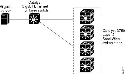
•![]() Cost-effective wiring closet (Figure 1-1)—A cost-effective way to connect many users to the wiring closet is to have a switch stack of up to nine Catalyst 3750 switches. To preserve switch connectivity if one switch in the stack fails, connect the switches as recommended in the hardware installation guide, and enable either cross-stack Etherchannel or cross-stack UplinkFast.
Cost-effective wiring closet (Figure 1-1)—A cost-effective way to connect many users to the wiring closet is to have a switch stack of up to nine Catalyst 3750 switches. To preserve switch connectivity if one switch in the stack fails, connect the switches as recommended in the hardware installation guide, and enable either cross-stack Etherchannel or cross-stack UplinkFast.
You can have redundant uplink connections, using small form-factor pluggable (SFP) modules in the switch stack to a Gigabit backbone switch, such as a Catalyst 4500 or Catalyst 3750G Gigabit switch. You can also create backup paths by using Fast Ethernet, Gigabit, or EtherChannel links. If one of the redundant connections fails, the other can serve as a backup path. If the Gigabit switch is cluster-capable, you can configure it and the switch stack as a switch cluster to manage them through a single IP address. The Gigabit switch can be connected to a Gigabit server through a 1000BASE-T connection.
Figure 1-1 Cost-Effective Wiring Closet
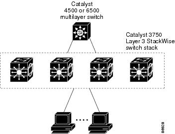
•![]() High-performance wiring closet (Figure 1-2) —For high-speed access to network resources, you can use Catalyst 3750 switches and switch stacks in the access layer to provide Gigabit Ethernet to the desktop. To prevent congestion, use QoS DSCP marking priorities on these switches. For high-speed IP forwarding at the distribution layer, connect the switches in the access layer to a Gigabit multilayer switch in the backbone, such as a Catalyst 4500 Gigabit switch or Catalyst 6500 Gigabit switch.
High-performance wiring closet (Figure 1-2) —For high-speed access to network resources, you can use Catalyst 3750 switches and switch stacks in the access layer to provide Gigabit Ethernet to the desktop. To prevent congestion, use QoS DSCP marking priorities on these switches. For high-speed IP forwarding at the distribution layer, connect the switches in the access layer to a Gigabit multilayer switch in the backbone, such as a Catalyst 4500 Gigabit switch or Catalyst 6500 Gigabit switch.
Each switch in this configuration provides users with a dedicated 1-Gbps connection to network resources. Using SFP modules also provides flexibility in media and distance options through fiber-optic connections.
Figure 1-2 High-Performance Wiring Closet
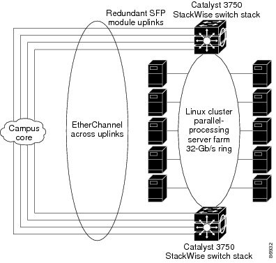
•![]() Server aggregation (Figure 1-3) and Linux server cluster (Figure 1-4)—You can use the switches and switch stacks to interconnect groups of servers, centralizing physical security and administration of your network. For high-speed IP forwarding at the distribution layer, connect the switches in the access layer to multilayer switches with routing capability. The Gigabit interconnections minimize latency in the data flow.
Server aggregation (Figure 1-3) and Linux server cluster (Figure 1-4)—You can use the switches and switch stacks to interconnect groups of servers, centralizing physical security and administration of your network. For high-speed IP forwarding at the distribution layer, connect the switches in the access layer to multilayer switches with routing capability. The Gigabit interconnections minimize latency in the data flow.
QoS and policing on the switches provide preferential treatment for certain data streams, if required. They segment traffic streams into different paths for processing. Security features on the switch ensure rapid handling of packets.
Dual homing of servers to dual switch stacks with redundant Gigabit EtherChannel and cross-stack EtherChannel provide fault tolerance from the server racks to the core.
Using dual SFP uplinks from the Catalyst 3750 switches provide redundant uplinks to the network core. Using SFP modules provides flexibility in media and distance options through fiber-optic connections.
The various lengths of stack cable available, ranging from 0.5 meter to 3 meters provide extended connections to the switch stacks the stack across multiple server racks, for multiple stack aggregation.
Figure 1-3 Server Aggregation
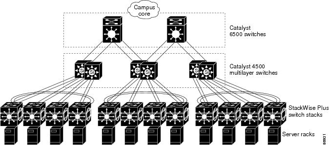
Figure 1-4 Linux Server Cluster
Small to Medium-Sized Network Using Catalyst 3750 Switches
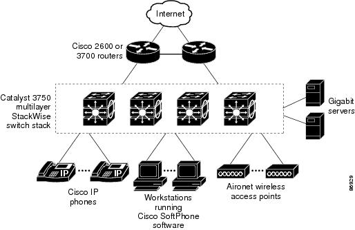
Figure 1-5 shows a configuration for a network of up to 500 employees. This network uses a Layer 3 Catalyst 3750 switch stack with high-speed uplinks to two routers. For network reliability and load balancing, this network has HSRP enabled on the routers and on the switch stack. This ensures connectivity to the Internet, WAN, and mission-critical network resources in case one of the routers or switches fails. The switch stack is using routed uplinks for faster failover. It is also configured with equal-cost routing for load sharing and redundancy. (A Layer 2 switch stack can use cross-stack EtherChannel for load sharing.)
The switch stack is connected to workstations, Cisco IP Phones, and local servers. This network uses VLANs to logically segment the network into well-defined broadcast groups and for security management. Data and multimedia traffic are configured on the same VLAN. Voice traffic from the Cisco IP Phones are configured on separate VVIDs. If data, multimedia, and voice traffic are assigned to the same VLAN, only one VLAN can be configured per wiring closet. For any switch port connected to Cisco IP Phones, 802.1P/Q QoS gives voice traffic forwarding-priority over data traffic. Cisco IP Phones not connected to Catalyst inline-power switches must be connected to AC power sources to receive power.
When an end station in one VLAN needs to communicate with an end station in another VLAN, a router or multilayer switch routes the traffic to the appropriate destination VLAN. In this network, the switch stack is providing inter-VLAN routing. VLAN access control lists (VLAN maps) on the switch stack provide intra-VLAN security and prevent unauthorized users from accessing critical pieces of the network.
In addition to inter-VLAN routing, the switch stack provides QoS mechanisms such as DSCP priorities to prioritize the different types of network traffic and to deliver high-priority traffic in a predictable manner. If congestion occurs, QoS drops low-priority traffic to allow delivery of high-priority traffic.
With the switch stack providing inter-VLAN routing and other network services, the routers focus on firewall services, Network Address Translation (NAT) services, voice-over-IP (VoIP) gateway services, and WAN and Internet access.
Figure 1-5 Catalyst 3750 Switch Stack in a Collapsed Backbone Configuration
Large Network Using Catalyst 3750 Switches
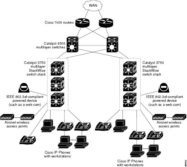
Switches in the wiring closet have traditionally been Layer 2-only devices, but as network traffic profiles evolve, switches in the wiring closet are increasingly employing multilayer services such as multicast management and traffic classification. Figure 1-6 shows a configuration for a network exclusively using multilayer switch stacks in the wiring closets and two backbone switches, such as the Catalyst 6000 switches, to aggregate up to ten wiring closets.
In the wiring closet, each switch stack has IGMP snooping enabled to efficiently forward multimedia and multicast traffic. QoS ACLs that either drop or mark nonconforming traffic based on bandwidth limits are also configured on each switch stack. VLAN maps provide intra-VLAN security and prevent unauthorized users from accessing critical pieces of the network. QoS features can limit bandwidth on a per-port or per-user basis. The switch ports are configured as either trusted or untrusted. You can configure a trusted port to trust the CoS value, the DSCP value, or the IP precedence. If you configure the port as untrusted, you can use an ACL to mark the frame in accordance with the network policy.
Each switch stack provides inter-VLAN routing. They provide proxy ARP services to determine IP and MAC address mapping, thereby removing this task from the routers and decreasing this type of traffic on the WAN links. These switch stacks also have redundant uplink connections to the backbone switches, with each uplink port configured as a trusted routed uplink to provide faster convergence in case of an uplink failure.
The routers and backbone switches have HSRP enabled for load balancing and redundant connectivity to guarantee mission-critical traffic.
Figure 1-6 Catalyst 3750 Switch Stacks in Wiring Closets in a Backbone Configuration
Where to Go Next
Before configuring the switch, review these sections for start up information:
•![]() "Using the Command-Line Interface"
"Using the Command-Line Interface"
 Feedback