- IP Multicast Routing Technology Overview
- Configuring Basic IP Multicast Routing
- Constraining IP Multicast in Switched Ethernet
- Configuring Multicast Routing over GRE Tunnel
- Configuring VRF-lite
- Configuring IGMP Snooping
- Configuring IGMP Proxy
- IGMP Explicit Tracking
- Configuring Protocol Independent Multicast (PIM)
- Configuring PIM MIB Extension for IP Multicast
- Configuring MSDP
- Configuring SSM
- Configuring the Service Discovery Gateway
- IP Multicast Optimization: Optimizing PIM Sparse Mode in a Large IP Multicast Deployment
- IP Multicast Optimization: Multicast Subsecond Convergence
- IP Multicast Optimization: IP Multicast Load Splitting across Equal-Cost Paths
- IP Multicast Optimization: SSM Channel Based Filtering for Multicast
- IP Multicast Optimization: IGMP State Limit
Configuring VRF-lite
Information About VRF-lite
VRF-lite is a feature that enables a service provider to support two or more VPNs, where IP addresses can be overlapped among the VPNs. VRF-lite uses input interfaces to distinguish routes for different VPNs and forms virtual packet-forwarding tables by associating one or more Layer 3 interfaces with each VRF. Interfaces in a VRF can be either physical, such as Ethernet ports, or logical, such as VLAN SVIs, but a Layer 3 interface cannot belong to more than one VRF at any time.
 Note | VRF-lite interfaces must be Layer 3 interfaces. |
VRF-lite includes these devices:
-
Customer edge (CE) devices provide customer access to the service provider network over a data link to one or more provider edge routers. The CE device advertises the site’s local routes to the provider edge router and learns the remote VPN routes from it. A Cisco Catalyst Switch can be a CE.
-
Provider edge (PE) routers exchange routing information with CE devices by using static routing or a routing protocol such as BGP, RIPv1, or RIPv2.
The PE is only required to maintain VPN routes for those VPNs to which it is directly attached, eliminating the need for the PE to maintain all of the service provider VPN routes. Each PE router maintains a VRF for each of its directly connected sites. Multiple interfaces on a PE router can be associated with a single VRF if all of these sites participate in the same VPN. Each VPN is mapped to a specified VRF. After learning local VPN routes from CEs, a PE router exchanges VPN routing information with other PE routers by using internal BGP (iBPG).
-
Provider routers (or core routers) are any routers in the service provider network that do not attach to CE devices.
With VRF-lite, multiple customers can share one CE, and only one physical link is used between the CE and the PE. The shared CE maintains separate VRF tables for each customer and switches or routes packets for each customer based on its own routing table. VRF-lite extends limited PE functionality to a CE device, giving it the ability to maintain separate VRF tables to extend the privacy and security of a VPN to the branch office.
The following figure displays a configuration where each Cisco Catalyst switch acts as multiple virtual CEs. Because VRF-lite is a Layer 3 feature, each interface in a VRF must be a Layer 3 interface.
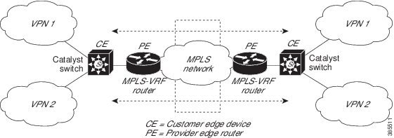
This figure illustrates the packet-forwarding process in a VRF-lite CE-enabled network.
-
When the CE receives a packet from a VPN, it looks up the routing table based on the input interface. When a route is found, the CE forwards the packet to the PE.
-
When the ingress PE receives a packet from the CE, it performs a VRF lookup. When a route is found, the router adds a corresponding MPLS label to the packet and sends it to the MPLS network.
-
When an egress PE receives a packet from the network, it strips the label and uses the label to identify the correct VPN routing table. The egress PE then performs the normal route lookup. When a route is found, it forwards the packet to the correct adjacency.
-
When a CE receives a packet from an egress PE, it uses the input interface to look up the correct VPN routing table. If a route is found, the CE forwards the packet within the VPN.
To configure VRF, create a VRF table and specify the Layer 3 interface associated with the VRF. You then configure the routing protocols in the VPN and between the CE and the PE. BGP is the preferred routing protocol used to distribute VPN routing information across the providers’ backbone. The VRF-lite network has three major components:
-
VPN route target communities—Lists all other members of a VPN community. You need to configure VPN route targets for each VPN community member.
-
Multiprotocol BGP peering of VPN community PE routers—Propagates VRF reachability information to all members of a VPN community. You need to configure BGP peering in all PE routers within a VPN community.
-
VPN forwarding—Transports all traffic between all VPN community members across a VPN service-provider network.
Guidelines for Configuring VRF-lite
IPv4 and IPv6
-
A switch with VRF-lite is shared by multiple customers, and all customers have their own routing tables.
-
Because customers use different VRF tables, you can reuse the same IP addresses. Overlapped IP addresses are allowed in different VPNs.
-
VRF-lite lets multiple customers share the same physical link between the PE and the CE. Trunk ports with multiple VLANs separate packets among customers. All customers have their own VLANs.
-
For the PE router, there is no difference between using VRF-lite or using multiple CEs. In , multiple virtual Layer 3 interfaces are connected to the VRF-lite device.
-
The Cisco Catalyst switch supports configuring VRF by using physical ports, VLAN SVIs, or a combination of both. You can connect SVIs through an access port or a trunk port.
-
A customer can use multiple VLANs as long because they do not overlap with those of other customers. A customer’s VLANs are mapped to a specific routing table ID that is used to identify the appropriate routing tables stored on the switch.
-
The Layer 3 TCAM resource is shared between all VRFs. To ensure that any one VRF has sufficient CAM space, use the maximum routes command.
-
A Cisco Catalyst switch using VRF can support one global network and multiple VRFs. The total number of routes supported is limited by the size of the TCAM.
-
A single VRF can be configured for both IPv4 and IPv6.
-
If an incoming packet's destination address is not found in the vrf table, the packet is dropped. Also, if insufficient TCAM space exists for a VRF route, hardware switching for that VRF is disabled and the corresponding data packets are sent to software for processing.
IPv4 Specific
-
You can use most routing protocols (BGP, OSPF, EIGRP, RIP and static routing) between the CE and the PE. However, we recommend using external BGP (EBGP) for these reasons:
-
BGP does not require multiple algorithms to communicate with multiple CEs.
-
BGP is designed for passing routing information between systems run by different administrations.
-
BGP makes simplifies passing attributes of the routes to the CE.
-
-
The Cisco Catalyst switch supports PIM-SM and PIM-SSM protocols.
-
The capability vrf-lite subcommand under router ospf should be used when configuring OSPF as the routing protocol between the PE and the CE.
IPv6 specific
-
VRF-aware OSPFv3, BGPv6, EIGRPv6, and IPv6 static routing are supported.
-
VRF-aware IPv6 route applications include: ping, telnet, ssh, tftp, ftp and traceroute. (This list does not include the Mgt interface, which is handled differently even though you can configure both IPv4 or IPv6 VRF under it.)
Topic 2.1
How to Configure VRF-lite
Configuring VRF-lite for IPv4
Configuring VRF-Aware Services
IP services can be configured on global interfaces and within the global routing instance. IP services are enhanced to run on multiple routing instances; they are VRF-aware. Any configured VRF in the system can be specified for a VRF-aware service.
VRF-aware services are implemented in platform-independent modules. VRF provides multiple routing instances in Cisco IOS. Each platform has its own limit on the number of VRFs it supports.
VRF-aware services have the following characteristics:
Configuring the User Interface for ARP
| Command or Action | Purpose | |
|---|---|---|
| Step 1 |
show ip arp vrf vrf-name Example: Switch# show ip arp vrf vrf-name |
Displays the ARP table (static and dynamic entries) in the specified VRF. |
| Step 2 | arp vrf
vrf-name ip-address mac-address ARPA Example: Switch(config)# arp vrf vrf-name ip-address mac-address ARPA |
Creates a static ARP entry in the specified VRF. |
Configuring Per-VRF for TACACS+ Servers
The per-VRF for TACACS+ servers feature enables you to configure per-virtual route forwarding (per-VRF) authentication, authorization, and accounting (AAA) on TACACS+ servers.
You can create the VRF routing table (shown in Steps 3 and 4) and configure the interface (Steps 6, 7, and 8). The actual configuration of per-VRF on a TACACS+ server is done in Steps 10 through 13.
Before configuring per-VRF on a TACACS+ server, you must have configured AAA and a server group.
| Command or Action | Purpose | |
|---|---|---|
| Step 1 |
enable Example: Switch> enable |
Enables privileged EXEC mode. Enter your password if prompted. |
| Step 2 |
configure terminal Example: Switch# configure terminal |
Enters global configuration mode. |
| Step 3 |
ip vrf vrf-name Example: Switch(config)# ip vrf vrf-name |
Configures a VRF table and enters VRF configuration mode. |
| Step 4 |
rd route-distinguisher Example: Switch (config-vrf)# rd route-distinguisher |
Creates routing and forwarding tables for a VRF instance. |
| Step 5 |
exit Example: Switch (config-vrf)# exit |
Exits VRF configuration mode. |
| Step 6 |
interface interface-name Example: Switch (config)# interface interface-name |
Configures an interface and enters interface configuration mode. |
| Step 7 |
vrf forwarding vrf-name Example: Switch (config-if)# vrf forwarding vrf-name |
Configures a VRF for the interface. |
| Step 8 |
ip address ip-address mask [secondary] Example: Switch (config-if)# ip address ip-address mask [secondary] |
Sets a primary or secondary IP address for an interface. |
| Step 9 |
exit Example: Switch (config-vrf)# exit |
Exits interface configuration mode. |
| Step 10 |
aaa group server tacacs+ group-name Example: Switch (config)# aaa group server tacacs+ tacacs1 |
Groups different TACACS+ server hosts into distinct lists and distinct methods and enters server-group configuration mode. |
| Step 11 |
server-private {ip-address | name} [nat] [single-connection] [port port-number] [timeout
seconds] [key [0 | 7] string] Example: Switch (config-sg-tacacs+)# server-private 10.1.1.1 port 19 key cisco |
Configures the IP address of the private TACACS+ server for the group server. |
| Step 12 |
vrf forwarding vrf-name Example: Switch (config-sg-tacacs+)# vrf forwarding vrf-name |
Configures the VRF reference of a AAA TACACS+ server group. |
| Step 13 |
ip tacacs source-interface subinterface-name Example: Switch (config-sg-tacacs+)# ip tacacs source-interface subinterface-name |
Uses the IP address of a specified interface for all outgoing TACACS+ packets. |
| Step 14 |
exit Example: Switch (config-sg-tacacs)# exit |
Exits server-group configuration mode. |
Switch> enable
Switch# configure terminal
Switch (config)# ip vrf cisco
Switch (config-vrf)# rd 100:1
Switch (config-vrf)# exit
Switch (config)# interface Loopback0
Switch (config-if)# vrf forwarding cisco
Switch (config-if)# ip address 10.0.0.2 255.0.0.0
Switch (config-if)# exit
Switch (config-sg-tacacs+)# vrf forwarding cisco
Switch (config-sg-tacacs+)# ip tacacs source-interface Loopback0
Switch (config-sg-tacacs)# exit
Configuring Multicast VRFs
| Command or Action | Purpose | |
|---|---|---|
| Step 1 |
configure terminal Example: Switch# configure terminal |
Enters global configuration mode. |
| Step 2 |
ip routing Example: Switch(config)# ip routing |
Enables IP routing. |
| Step 3 |
ip vrf vrf-name Example: Switch(config)# ip vrf vrf-name |
Configures a VRF table and enters VRF configuration mode. |
| Step 4 | ip multicast-routing vrf vrf-name Example: Switch(config-vrf)# ip multicast-routing vrf vrf-name |
(Optional) Enables global multicast routing for VRF table. |
| Step 5 |
rd route-distinguisher Example: Switch (config-vrf)# rd route-distinguisher |
Creates a VRF table by specifying a route distinguisher. Enter either an AS number and an arbitrary number (xxx:y) or an IP address and arbitrary number (A.B.C.D:y). |
| Step 6 | route-target {export | import | both} route-target-ext-community Example: Switch(config-vrf)# route-target {export | import | both} route-target-ext-community
|
Creates a list of import, export, or import and export route target communities for the specified VRF. Enter either an AS system number and an arbitrary number (xxx:y) or an IP address and an arbitrary number (A.B.C.D:y). The route-target-ext-community value should be the same as the route-distinguisher value entered in Step 4. |
| Step 7 | import map route-map Example: Switch(config-vrf)# import map route-map |
(Optional) Associates a route map with the VRF. |
| Step 8 |
interface interface-id Example: Switch (config)# interface interface-id |
Enters interface configuration mode and specifies the Layer 3 interface to be associated with the VRF. The interface can be a routed port or a SVI. |
| Step 9 |
vrf forwarding vrf-name Example: Switch (config-sg-tacacs+)# vrf forwarding vrf-name |
Associates the VRF with the Layer 3 interface. |
| Step 10 |
ip address ip-address mask Example: Switch (config-if)# ip address ip-address mask |
Configures IP address for the Layer 3 interface. |
| Step 11 | ip pim
sparse-mode Example: Switch(config-if)# ip pim sparse-mode |
Enables PIM on the VRF-associated Layer 3 interface. |
| Step 12 | end Example: Switch(config-if)# end |
Returns to privileged EXEC mode. |
| Step 13 | show ip vrf [brief | detail | interfaces] [vrf-name] Example: show ip vrf [brief | detail | interfaces] [vrf-name]
|
Verifies the configuration. Display information about the configured VRFs. |
| Step 14 | copy running-config startup-config Example: Switch# copy running-config startup-config |
(Optional) Saves your entries in the configuration file. |
The following example shows how to configure multicast within a VRF table:
Switch(config)# ip routing
Switch(config)# ip vrf multiVrfA
Switch(config-vrf)# ip multicast-routing vrf multiVrfA
Switch(config-vrf)# interface GigabitEthernet3/1/0
Switch(config-if)# vrf forwarding multiVrfA
Switch(config-if)# ip address 172.21.200.203 255.255.255.0
Switch(config-if)# ip pim sparse-mode
Configuring a VPN Routing Session
| Command or Action | Purpose | |
|---|---|---|
| Step 1 |
configure terminal Example: Switch# configure terminal |
Enters global configuration mode. |
| Step 2 |
router ospf
process-id
vrf vrf-name Example: Switch(config)# router ospf process-id vrf vrf-name |
Enables OSPF routing, specifies a VPN forwarding table, and enters router configuration mode. |
| Step 3 |
log-adjacency-changes Example: Switch(config-router)# log-adjacency-changes |
(Optional) Logs changes in the adjacency state (the default state). |
| Step 4 |
redistribute bgp
autonomous-system-number subnets Example: Switch(config-router)# redistribute bgp autonomous-system-number subnets |
Sets the switch to redistribute information from the BGP network to the OSPF network. |
| Step 5 | network
network-number
area
area-id Example: Switch(config-router)# network network-number area area-id |
Defines a network address and mask on which OSPF runs and the area ID for that network address. |
| Step 6 | end Example: Switch(config-router)# end |
Returns to privileged EXEC mode. |
| Step 7 | show ip ospf
process-id
Example: Switch# show ip ospf process-id |
Verifies the configuration of the OSPF network. |
| Step 8 | copy running-config startup-config Example: Switch# copy running-config startup-config |
(Optional) Saves your entries in the configuration file. Use the no router ospf process-id vrf vrf-name global configuration command to disassociate the VPN forwarding table from the OSPF routing process. |
Switch(config)# ip vrf VRF-RED
Switch(config-vrf)# rd 1:1
Switch(config-vrf)# exit
Switch(config)# router eigrp virtual-name
Switch(config-router)# address-family ipv4 vrf VRF-RED autonomous-system 1
Switch(config-router-af)# network 10.0.0.0 0.0.0.255
Switch(config-router-af)# topology base
Switch(config-router-topology)# default-metric 10000 100 255 1 1500
Switch(config-router-topology)# exit-af-topology
Switch(config-router-af)# exit-address-family
Configuring BGP PE to CE Routing Sessions
| Command or Action | Purpose | |
|---|---|---|
| Step 1 |
configure terminal Example: Switch# configure terminal |
Enters global configuration mode. |
| Step 2 |
router bgp
autonomous-system-number
Example: Switch(config)# router bgp autonomous-system-number |
Configures the BGP routing process with the AS number passed to other BGP routers and enters router configuration mode. |
| Step 3 |
network
network-number
mask
network-mask Example: Switch(config-router)# network network-number mask network-mask |
Specifies a network and mask to announce using BGP. |
| Step 4 | redistribute ospf
process-id match internal Example: Switch(config-router)# redistribute ospf process-id match internal |
Sets the switch to redistribute OSPF internal routes. |
| Step 5 | network
network-number
area
area-id Example: Switch(config-router)# network network-number area area-id |
Defines a network address and mask on which OSPF runs and the area ID for that network address. |
| Step 6 | address-family ipv4 vrf vrf-name Example: Switch(config-router-af)# address-family ipv4 vrf vrf-name |
Defines BGP parameters for PE to CE routing sessions and enters VRF address-family mode. |
| Step 7 | neighbor
address
remote-as
as-number Example: Switch(config-router-af)# neighbor address remote-as as-number |
Defines a BGP session between PE and CE routers. |
| Step 8 | neighbor
address
activate
Example: Switch(config-router-af)# neighbor address activate |
Activates the advertisement of the IPv4 address family. |
| Step 9 | end Example: Switch(config-router-af)# end |
Returns to privileged EXEC mode. |
| Step 10 | show ip bgp [ipv4] [neighbors] Example: Switch# show ip bgp [ipv4] [neighbors] |
Verifies BGP configuration. Use the no router bgp autonomous-system-number global configuration command to delete the BGP routing process. Use the command with keywords to delete routing characteristics. |
Configuring IPv4 VRFs
| Command or Action | Purpose | |||
|---|---|---|---|---|
| Step 1 | configure terminal
Example: Switch# configure terminal |
Enters global configuration mode. | ||
| Step 2 | ip routing Example: Switch# configure terminal |
Enters global configuration mode. | ||
| Step 3 | ip vrf vrf-name Example: Switch(config)# ip vrf vrf-name |
Names the VRF and enters VRF configuration mode. | ||
| Step 4 | rd route-distinguisher Example: Switch(config-vrf)# rd route-distinguisher |
Creates a VRF table by specifying a route distinguisher. Enter either an Autonomous System number number and an arbitrary number (xxx:y) or an IP address and arbitrary number (A.B.C.D:y). | ||
| Step 5 | route-target {export | import | both} route-target-ext-community Example: Switch(config-vrf)# route-target {export | import | both} route-target-ext-community
|
Creates a list of import, export, or import and export route target communities for the specified VRF. Enter either an AS system number and an arbitrary number (xxx:y) or an IP address and an arbitrary number (A.B.C.D:y).
| ||
| Step 6 | import map route-map Example: Switch(config-vrf)# import map route-map |
(Optional) Associates a route map with the VRF. | ||
| Step 7 | interface interface-id Example: Switch(config-vrf)# interface interface-id |
Enters interface configuration mode and specify the Layer 3 interface to be associated with the VRF. The interface can be a routed port or SVI. | ||
| Step 8 | vrf forwarding vrf-name Example: Switch(config-if)# vrf forwarding vrf-name |
Associates the VRF with the Layer 3 interface. | ||
| Step 9 | end Example: Switch(config-if)# end |
Returns to privileged EXEC mode. | ||
| Step 10 | show ip vrf [brief | detail | interfaces] [vrf-name] Example: Switch# show ip vrf [brief | detail | interfaces] [vrf-name] |
Verifies the configuration. Displays information about the configured VRFs. | ||
| Step 11 | copy running-config startup-config Example: Switch# copy running-config startup-config |
(Optional) Saves your entries in the configuration file.
Use the no ip vrf vrf-name global configuration command to delete a VRF and to remove all interfaces from it. Use the no vrf forwarding interface configuration command to remove an interface from the VRF. |
Configuring VRF-lite for IPv6
Configuring VRF-Aware Services
IPv6 services can be configured on global interfaces and within the global routing instance. IPv6 services are enhanced to run on multiple routing instances; they are VRF-aware. Any configured VRF in the system can be specified for a VRF-aware service.
VRF-aware services are implemented in platform-independent modules. VRF provides multiple routing instances in Cisco IOS. Each platform has its own limit on the number of VRFs it supports.
VRF-aware services have the following characteristics:
-
The user can ping a host in a user-specified VRF.
-
Neighbor Discovery entries are learned in separate VRFs. The user can display Neighbor Discovery (ND) entries for specific VRFs.
-
Ping
-
Unicast Reverse Path Forwarding (uRPF)
-
Traceroute
-
FTP and TFTP
-
Telnet and SSH
-
NTP
- Configuring the User Interface for PING
- Configuring the User Interface for uRPF
- Configuring the User Interface for Traceroute
- Configuring the User Interface for Telnet and SSH
- Configuring the User Interface for NTP
Configuring the User Interface for PING
| Command or Action | Purpose | |
|---|---|---|
| Step 1 |
ping vrf vrf-name
ipv6-host Example: Switch# ping vrf vrf-name ipv6-host |
Pings an IPv6 host or address in the specified VRF. |
Configuring the User Interface for uRPF
You can configure uRPF on an interface assigned to a VRF. Source lookup is performed in the VRF table
| Command or Action | Purpose | |
|---|---|---|
| Step 1 |
configure terminal Example: Switch# configure terminal |
Enters global configuration mode. |
| Step 2 |
interface interface-id Example: Switch (config)# interface interface-id |
Enters interface configuration mode and specifies the Layer 3 interface to configure. |
| Step 3 |
no switchport Example: Switch (config-if)# no switchport |
Removes the interface from Layer 2 configuration mode if it is a physical interface. |
| Step 4 |
vrf forwarding vrf-name Example: Switch (config-if)# vrf forwarding vrf-name |
Configures VRF on the interface. |
| Step 5 |
ipv6 address ip-address subnet-mask Example: Switch (config-if)# ip address ip-address mask |
Enters the IPv6 address for the interface. |
| Step 6 | ipv6 verify unicast source reachable-via rx allow-default Example: Switch(config-if)# ipv6 verify unicast source reachable-via rx allow-default |
Enables uRPF on the interface. |
| Step 7 | end Example: Switch(config-if)# end |
Returns to privileged EXEC mode. |
Configuring the User Interface for Traceroute
| Command or Action | Purpose | |
|---|---|---|
| Step 1 | traceroute vrf
vrf-name ipv6address
Example: Switch# traceroute vrf vrf-name ipv6address |
Specifies the name of a VPN VRF in which to find the destination address. |
Configuring the User Interface for Telnet and SSH
| Command or Action | Purpose | |
|---|---|---|
| Step 1 |
telnet
ipv6-address/vrf
vrf-name Example: Switch# telnet ipv6-address/vrf vrf-name |
Connects through Telnet to an IPv6 host or address in the specified VRF. |
| Step 2 |
ssh -l
username
-vrf
vrf-name
ipv6-host Example: Switch# ssh -l username -vrf vrf-name ipv6-host |
Connects through SSH to an IPv6 host or address in the specified VRF. |
Configuring the User Interface for NTP
Configuring IPv6 VRFs
| Command or Action | Purpose | |||
|---|---|---|---|---|
| Step 1 | configure terminal
Example: Switch# configure terminal |
Enters global configuration mode. | ||
| Step 2 | vrf definition vrf-name Example: Switch(config)# vrf definition vrf-name |
Names the VRF and enters VRF configuration mode. | ||
| Step 3 | rd route-distinguisher Example: Switch(config-vrf)# rd route-distinguisher |
(Optional) Creates a VRF table by specifying a route distinguisher. Enter either an Autonomous System number and an arbitrary number (xxx:y) or an IP address and arbitrary number (A.B.C.D:y). | ||
| Step 4 |
address-family
ipv4 | ipv6 Example: Switch(config-vrf)# address-family ipv4 | ipv6 |
(Optional) IPv4 by default. Configuration MUST for IPv6. | ||
| Step 5 | route-target {export | import | both} route-target-ext-community Example: Switch(config-vrf)# route-target {export | import | both} route-target-ext-community
|
Creates a list of import, export, or import and export route target communities for the specified VRF. Enter either an AS system number and an arbitrary number (xxx:y) or an IP address and an arbitrary number (A.B.C.D:y).
| ||
| Step 6 | exit-address-family Example: Switch(config-vrf)# exit-address-family |
Exits VRF address-family configuration mode and return to VRF configuration mode. | ||
| Step 7 | vrf definition vrf-name Example: Switch(config)# vrf definition vrf-name |
Enters VRF configuration mode. | ||
| Step 8 | ipv6 multicast multitopology Example: Switch(config-vrf-af)# ipv6 multicast multitopology |
Enables multicast specific RPF topology. | ||
| Step 9 | address-family ipv6 multicast Example: Switch(config-vrf)# address-family ipv6 multicast |
Enter multicast IPv6 address-family. | ||
| Step 10 | end Example: Switch(config-vrf-af)# end |
Returns to privileged EXEC mode. |
This example shows how to configure VRFs:
Switch(config)#  vrf definition red
Switch(config-vrf)# rd 100:1
Switch(config-vrf)# address family ipv6
Switch(config-vrf-af)# route-target both 200:1
Switch(config-vrf)# exit-address-family
Switch(config-vrf)# vrf definition red
Switch(config-if)# ipv6 multicast multitopology
Switch(config-if)# address-family ipv6 multicast
Switch(config-vrf-af)# end
Switch#
Associating Interfaces to the Defined VRFs
| Command or Action | Purpose | |
|---|---|---|
| Step 1 | interface interface-id Example: Switch(config-vrf)# interface interface-id |
Enters interface configuration mode and specify the Layer 3 interface to be associated with the VRF. The interface can be a routed port or SVI. |
| Step 2 | no switchport
Example: Switch(config-if)# no switchport |
Removes the interface from configuration mode if it is a physical interface. |
| Step 3 | vrf forwarding vrf-name Example: Switch(config-if)# vrf forwarding vrf-name |
Associates the VRF with the Layer 3 interface. |
| Step 4 | ipv6 enable Example: Switch(config-if)# ipv6 enable |
Enable IPv6 on the interface. |
| Step 5 | ipv6 address ip-address subnet-mask Example: Switch(config-if)# ipv6 address ip-address subnet-mask |
Enters the IPv6 address for the interface. |
| Step 6 | show ipv6 vrf [brief | detail | interfaces] [vrf-name] Example: Switch# show ipv6 vrf [brief | detail | interfaces] [vrf-name] |
Verifies the configuration. Displays information about the configured VRFs. |
| Step 7 | copy running-config startup-config Example: Switch# copy running-config startup-config |
(Optional) Saves your entries in the configuration file. |
Switch(config-vrf)# interface ethernet0/1
Switch(config-if)# vrf forwarding red
Switch(config-if)# ipv6 enable
Switch(config-if)# ipv6 address 5000::72B/64
Populate VRF with Routes via Routing Protocols
Configuring VRF Static Routes
| Command or Action | Purpose | |
|---|---|---|
| Step 1 | configure terminal
Example: Switch# configure terminal |
Enters global configuration mode. |
| Step 2 | ipv6 route [vrf vrf-name] ipv6-prefix/prefix-length {ipv6-address | interface-type
interface-number [ipv6-address]}
Example: Switch(config)# ipv6 route [vrf vrf-name] ipv6-prefix/prefix-length {ipv6-address | interface-type interface-number [ipv6-address]}
|
To configure static routes specific to VRF. |
Switch(config)# ipv6 route vrf v6a 7000::/64 TenGigabitEthernet32 4000::2
Configuring OSPFv3 Router Process
| Command or Action | Purpose | |
|---|---|---|
| Step 1 | configure terminal
Example: Switch# configure terminal |
Enters global configuration mode. |
| Step 2 |
router ospfv3 process-id Example: Switch(config)# router ospfv3 process-id |
Enables OSPFv3 router configuration mode for the IPv6 address family. |
| Step 3 |
area
area-ID [default-cot | nssa | stub] Example: Switch(config-router)# area area-ID [default-cot | nssa | stub] |
Configures the OSPFv3 area. |
| Step 4 |
router-id
router-id Example: Switch(config-router)# router-id router-id |
Use a fixed router ID. |
| Step 5 |
address-family ipv6 unicast vrf
vrf-name Example: Switch(config-router)# address-family ipv6 unicast vrf vrf-name |
Enters IPv6 address family configuration mode for OSPFv3 in VRF vrf-name |
| Step 6 | redistribute source-protocol [process-id] options Example: Switch(config-router)# redistribute source-protocol [process-id] options |
Redistributes IPv6 routes from one routing domain into another routing domain. |
| Step 7 | end Example: Switch(config-router)# end |
Returns to privileged EXEC mode. |
Switch(config-router)# router ospfv3 1
Switch(config-router)# router-id 1.1.1.1
Switch(config-router)# address-family ipv6 unicast
Switch(config-router-af)# exit-address-family
Enabling OSPFv3 on an Interface
| Command or Action | Purpose | |
|---|---|---|
| Step 1 | configure terminal
Example: Switch# configure terminal |
Enters global configuration mode. |
| Step 2 | interface type-number Example: Switch(config-vrf)# interface type-number |
Specifies an interface type and number, and places the switch in interface configuration mode. |
| Step 3 |
ospfv3
process-id
area
area-ID
ipv6 [instance
instance-id] Example: Switch(config-if)# ospfv3 process-id area area-ID ipv6 [instance instance-id] |
Enables OSPFv3 on an interface with IPv6 AF. |
| Step 4 | end Example: Switch(config-if)# end |
Returns to privileged EXEC mode. |
Switch(config)# interface GigabitEthernet2/1
Switch(config-if)# no switchport
Switch(config-if)# ipv6 address 4000::2/64
Switch(config-if)# ipv6 enable
Switch(config-if)# ipv6 ospf 1 area 0
Switch(config-if)# end
Configuring EIGRPv6 Routing Process
| Command or Action | Purpose | |
|---|---|---|
| Step 1 | configure terminal
Example: Switch# configure terminal |
Enters global configuration mode. |
| Step 2 |
router eigrp virtual-instance-name Example: Switch(config)# router eigrp virtual-instance-name |
Configures the EIGRP routing process and enters router configuration mode. |
| Step 3 |
address-family ipv6 vrf
vrf-name
autonomous-system
autonomous-system-number Example: Switch(config-router)# address-family ipv6 vrf vrf-name autonomous-system autonomous-system-number |
Enables EIGRP IPv6 VRF-Lite and enters address family configuration mode. |
| Step 4 |
topology {base | topology-name
tid
number Example: Switch(config-router-af)# topology {base | topology-name tid number
|
Configures an EIGRP process to route IP traffic under the specified topology instance and enters address family topology configuration mode. |
| Step 5 | exit-aftopology Example: Switch(config-router-af-topology)# exit-aftopology |
Exits address family topology configuration mode. |
| Step 6 | eigrp router-id ip-address Example: Switch(config-router)# eigrp router-id ip-address |
Enables the use of a fixed router-id. |
| Step 7 | end Example: Switch(config-router)# end |
Exits router configuration mode. |
Switch(config)# router eigrp test
Switch(config-router)# address-family ipv6 unicast vrf b1 autonomous-system 10
Switch(config-router-af)# topology base
Switch(config-router-af-topology)# exit-af-topology
Switch(config-router)# eigrp router-id 2.3.4.5
Switch(config-router)# exit-address-family
Configuring EBGPv6 Routing Process
Switch(config)# router bgp 2
Switch(config-router)# bgp router-id 2.2.2.2
Switch(config-router)# bgp log-neighbor-changes
Switch(config-router)# no bgp default ipv4-unicast
Switch(config-router)# neighbor 2500::1 remote-as 1
Switch(config-router)# neighbor 4000::2 remote-as 3
Switch(config-router)# address-family ipv6 vrf b1
Switch(config-router-af)# network 2500::/64
Switch(config-router-af)# network 4000::/64
Switch(config-router-af)# neighbor 2500::1 remote-as 1
Switch(config-router-af)# neighbor 2500::1 activate
Switch(config-router-af)# neighbor 4000::2 remote-as 3
Switch(config-router-af)# neighbor 4000::2 activate
Switch(config-router-af)# exit-address-family
Additional Information for VRF-lite
VPN Co-existence Between IPv4 and IPv6
Backward compatibility between the “older” CLI for configuring IPv4 and the “new” CLI for IPv6 exists. This means that a configuration might contain both CLI. The IPv4 CLI retains the ability to have on the same interface, an IP address defined within a VRF as well as an IPv6 address defined in the global routing table.
vrf definition red
 rd 100:1
 address family ipv6
 route-target both 200:1
 exit-address-family
!
ip vrf blue
 rd 200:1
 route-target both 200:1
!
interface Ethernet0/0
 vrf forwarding red
 ip address 50.1.1.2 255.255.255.0
 ipv6 address 4000::72B/64
!
interface Ethernet0/1
 vrf forwarding blue
 ip address 60.1.1.2 255.255.255.0
 ipv6 address 5000::72B/64
In this example, all addresses (v4 and v6) defined for Ethernet0/0 refer to VRF red whereas for Ethernet0/1, the IP address refers to VRF blue but the ipv6 address refers to the global IPv6 routing table.
Verifying VRF-lite Configuration
Displaying IPv4 VRF-lite Status
To display information about VRF-lite configuration and status, perform one of the following tasks:
Switch# show ip mroute 226.0.0.2
IP Multicast Routing Table
Flags: S - Sparse, B - Bidir Group, s - SSM Group, C - Connected,
       L - Local, P - Pruned, R - RP-bit set, F - Register flag,
       T - SPT-bit set, J - Join SPT, M - MSDP created entry, E - Extranet,
       X - Proxy Join Timer Running, A - Candidate for MSDP Advertisement,
       U - URD, I - Received Source Specific Host Report,
       Z - Multicast Tunnel, z - MDT-data group sender,
       Y - Joined MDT-data group, y - Sending to MDT-data group,
       G - Received BGP C-Mroute, g - Sent BGP C-Mroute,
       N - Received BGP Shared-Tree Prune, n - BGP C-Mroute suppressed,
       Q - Received BGP S-A Route, q - Sent BGP S-A Route,
       V - RD & Vector, v - Vector, p - PIM Joins on route,
       x - VxLAN group, c - PFP-SA cache created entry
Outgoing interface flags: H - Hardware switched, A - Assert winner, p - PIM Join
Timers: Uptime/Expires
Interface state: Interface, Next-Hop or VCD, State/Mode

(*, 226.0.0.2), 00:01:17/stopped, RP 1.11.1.1, flags: SJCF
  Incoming interface: Null, RPF nbr 0.0.0.0
  Outgoing interface list:
    Vlan100, Forward/Sparse, 00:01:17/00:02:36

(5.0.0.11, 226.0.0.2), 00:01:17/00:01:42, flags: FT
  Incoming interface: Vlan5, RPF nbr 0.0.0.0
  Outgoing interface list:
    Vlan100, Forward/Sparse, 00:01:17/00:02:36
Displaying IPv6 VRF-lite Status
To display information about VRF-lite configuration and status, perform one of the following tasks:
show ipv6 mroute vrf vrf1 FF05:ABCD:0:0:0:0:0:1
Multicast Routing Table
Flags: S - Sparse, B - Bidir Group, s - SSM Group,
C - Connected, L - Local, I - Received Source Specific Host Report,
P - Pruned, R - RP-bit set, F - Register flag, T - SPT-bit set,
J - Join SPT, Y - Joined MDT-data group,
y - Sending to MDT-data group

g - BGP signal originated, G - BGP Signal received,
N - BGP Shared-Tree Prune received, n - BGP C-Mroute suppressed,
q - BGP Src-Active originated, Q - BGP Src-Active received
E - Extranet
Timers: Uptime/Expires
Interface state: Interface, State

(*, FF05:ABCD::1), 00:06:22/never, RP 1010:ABCD::10, flags: SCJ
Incoming interface: Port-channel33
RPF nbr: FE80::2E31:24FF:FE06:134A
Immediate Outgoing interface list:
TenGigabitEthernet4/0/18, Forward, 00:06:22/never

(3232:ABCD::2, FF05:ABCD::1), 00:04:54/00:02:16, flags: SJT
Incoming interface: Port-channel33
RPF nbr: FE80::2E31:24FF:FE06:134A
Inherited Outgoing interface list:
TenGigabitEthernet4/0/18, Forward, 00:06:22/never
Switch# show ipv6 mfib vrf vrf1 FF05:ABCD:0:0:0:0:0:1
Entry Flags:    C - Directly Connected, S - Signal, IA - Inherit A flag,
                ET - Data Rate Exceeds Threshold, K - Keepalive
                DDE - Data Driven Event, HW - Hardware Installed
                ME - MoFRR ECMP entry, MNE - MoFRR Non-ECMP entry, MP - MFIB
                MoFRR Primary, RP - MRIB MoFRR Primary, P - MoFRR Primary
                MS  - MoFRR  Entry in Sync, MC - MoFRR entry in MoFRR Client.
I/O Item Flags: IC - Internal Copy, NP - Not platform switched,
                NS - Negate Signalling, SP - Signal Present,
                A - Accept, F - Forward, RA - MRIB Accept, RF - MRIB Forward,
                MA - MFIB Accept, A2 - Accept backup,
                RA2 - MRIB Accept backup, MA2 - MFIB Accept backup

Forwarding Counts: Pkt Count/Pkts per second/Avg Pkt Size/Kbits per second
Other counts:      Total/RPF failed/Other drops
I/O Item Counts:   FS Pkt Count/PS Pkt Count
VRF testvrf1
 (*,FF05:ABCD::1) Flags: C HW
   SW Forwarding: 0/0/0/0, Other: 0/0/0
   HW Forwarding:   295/0/512/0, Other: 0/0/0
   Port-channel33 Flags: A NS
   TenGigabitEthernet4/0/18 Flags: F NS
     Pkts: 0/0
 (3232:ABCD::2,FF05:ABCD::1) Flags: HW
   SW Forwarding: 50/0/512/0, Other: 111/0/111
   HW Forwarding:   4387686/14849/512/59398, Other: 0/0/0
   Port-channel33 Flags: A
   TenGigabitEthernet4/0/18 Flags: F NS
     Pkts: 0/50

Switch#
Configuration Examples for VRF-lite
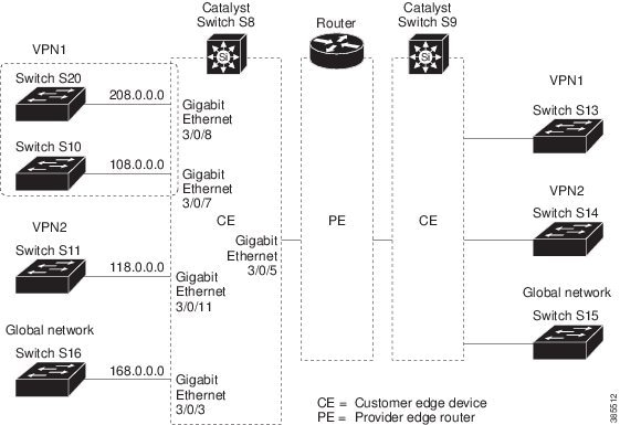
Configuration Example for IPv4 VRF-lite
OSPF is the protocol used in VPN1, VPN2, and the global network. BGP is used in the CE to PE connections. The example commands show how to configure the CE switch S8 and include the VRF configuration for switches S20 and S11 and the PE router commands related to traffic with switch S8. Commands for configuring the other switches are not included but would be similar.
Configuring Switch S8
Switch# configure terminal
Enter configuration commands, one per line.  End with CNTL/Z.
Switch(config)# ip routing
Switch(config)# ip vrf v11
Switch(config-vrf)# rd 800:1
Switch(config-vrf)# route-target export 800:1
Switch(config-vrf)# route-target import 800:1
Switch(config-vrf)# exit
Switch(config)# ip vrf v12
Switch(config-vrf)# rd 800:2
Switch(config-vrf)# route-target export 800:2
Switch(config-vrf)# route-target import 800:2
Switch(config-vrf)# exit
Switch(config)# interface loopback1
Switch(config-if)# vrf forwarding v11
Switch(config-if)# ip address 8.8.1.8 255.255.255.0
Switch(config-if)# exit

Switch(config)# interface loopback2
Switch(config-if)# vrf forwarding v12
Switch(config-if)# ip address 8.8.2.8 255.255.255.0
Switch(config-if)# exit

Switch(config)# interface FastEthernet3/5
Switch(config-if)# switchport trunk encapsulation dot1q
Switch(config-if)# switchport mode trunk
Switch(config-if)# no ip address
Switch(config-if)# exit

Switch(config)# interface FastEthernet3/8
Switch(config-if)# switchport access vlan 208
Switch(config-if)# no ip address
Switch(config-if)# exit

Switch(config)# interface FastEthernet3/11
Switch(config-if)# switchport trunk encapsulation dot1q
Switch(config-if)# switchport mode trunk
Switch(config-if)# no ip address
Switch(config-if)# exit
Switch(config)# interface Vlan10
Switch(config-if)# vrf forwarding v11
Switch(config-if)# ip address 38.0.0.8 255.255.255.0
Switch(config-if)# exit

Switch(config)# interface Vlan20
Switch(config-if)# vrf forwarding v12
Switch(config-if)# ip address 83.0.0.8 255.255.255.0
Switch(config-if)# exit

Switch(config)# interface Vlan118
Switch(config-if)# vrf forwarding v12
Switch(config-if)# ip address 118.0.0.8 255.255.255.0
Switch(config-if)# exit

Switch(config)# interface Vlan208
Switch(config-if)# vrf forwarding v11
Switch(config-if)# ip address 208.0.0.8 255.255.255.0
Switch(config-if)# exit
Switch(config)# router ospf 1 vrf vl1
Switch(config-router)# redistribute bgp 800 subnets
Switch(config-router)# network 208.0.0.0 0.0.0.255 area 0
Switch(config-router)# exit
Switch(config)# router ospf 2 vrf vl2
Switch(config-router)# redistribute bgp 800 subnets
Switch(config-router)# network 118.0.0.0 0.0.0.255 area 0
Switch(config-router)# exit
Switch(config)# router bgp 800
Switch(config-router)# address-family ipv4 vrf vl2
Switch(config-router-af)# redistribute ospf 2 match internal
Switch(config-router-af)# neighbor 83.0.0.3 remote-as 100
Switch(config-router-af)# neighbor 83.0.0.3 activate
Switch(config-router-af)# network 8.8.2.0 mask 255.255.255.0
Switch(config-router-af)# exit

Switch(config-router)# address-family ipv4 vrf vl1
Switch(config-router-af)# redistribute ospf 1 match internal
Switch(config-router-af)# neighbor 38.0.0.3 remote-as 100
Switch(config-router-af)# neighbor 38.0.0.3 activate
Switch(config-router-af)# network 8.8.1.0 mask 255.255.255.0
Switch(config-router-af)# end
Configuring Switch S20
Switch# configure terminal
Enter configuration commands, one per line.  End with CNTL/Z.
Switch(config)# ip routing
Switch(config)# interface Fast Ethernet 0/7
Switch(config-if)# no switchport
Switch(config-if)# ip address 208.0.0.20 255.255.255.0
Switch(config-if)# exit

Switch(config)# router ospf 101
Switch(config-router)# network 208.0.0.0 0.0.0.255 area 0
Switch(config-router)# end
Configuring Switch S11
Switch# configure terminal
Enter configuration commands, one per line.  End with CNTL/Z.
Switch(config)# ip routing
Switch(config)# interface Gigabit Ethernet 0/3
Switch(config-if)# switchport trunk encapsulation dot1q
Switch(config-if)# switchport mode trunk
Switch(config-if)# no ip address
Switch(config-if)# exit

Switch(config)# interface Vlan118
Switch(config-if)# ip address 118.0.0.11 255.255.255.0
Switch(config-if)# exit

Switch(config)# router ospf 101
Switch(config-router)# network 118.0.0.0 0.0.0.255 area 0
Switch(config-router)# end
Configuring the PE Switch S3
Router# configure terminal
Enter configuration commands, one per line.  End with CNTL/Z.
Router(config)# ip vrf v1
Router(config-vrf)# rd 100:1
Router(config-vrf)# route-target export 100:1
Router(config-vrf)# route-target import 100:1
Router(config-vrf)# exit

Router(config)# ip vrf v2
Router(config-vrf)# rd 100:2
Router(config-vrf)# route-target export 100:2
Router(config-vrf)# route-target import 100:2
Router(config-vrf)# exit

Router(config)# ip cef
Router(config)# interface Loopback1
Router(config-if)# vrf forwarding v1
Router(config-if)# ip address 3.3.1.3 255.255.255.0
Router(config-if)# exit

Router(config)# interface Loopback2
Router(config-if)# vrf forwarding v2
Router(config-if)# ip address 3.3.2.3 255.255.255.0
Router(config-if)# exit

Router(config)# interface Fast Ethernet3/0.10
Router(config-if)# encapsulation dot1q 10
Router(config-if)# vrf forwarding v1
Router(config-if)# ip address 38.0.0.3 255.255.255.0
Router(config-if)# exit

Router(config)# interface Fast Ethernet3/0.20
Router(config-if)# encapsulation dot1q 20
Router(config-if)# vrf forwarding v2
Router(config-if)# ip address 83.0.0.3 255.255.255.0
Router(config-if)# exit

Router(config)# router bgp 100
Router(config-router)# address-family ipv4 vrf v2
Router(config-router-af)# neighbor 83.0.0.8 remote-as 800
Router(config-router-af)# neighbor 83.0.0.8 activate
Router(config-router-af)# network 3.3.2.0 mask 255.255.255.0
Router(config-router-af)# exit
Router(config-router)# address-family ipv4 vrf vl
Router(config-router-af)# neighbor 83.0.0.8 remote-as 800
Router(config-router-af)# neighbor 83.0.0.8 activate
Router(config-router-af)# network 3.3.1.0 mask 255.255.255.0
Router(config-router-af)# end
Configuration Example for IPv6 VRF-lite
The following topology illustrates how to use OSPFv3 for CE-PE routing.
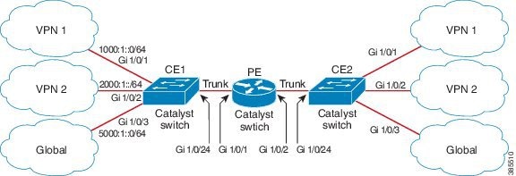
Configuring CE1 Switch
ipv6 unicast-routing
vrf definition v1
 rd 100:1
 !
address-family ipv6
 exit-address-family
!

vrf definition v2
 rd 200:1
 !
address-family ipv6
 exit-address-family
!

interface Vlan100
 vrf forwarding v1
 ipv6 address 1000:1::1/64
 ospfv3 100 ipv6 area 0
!

interface Vlan200
 vrf forwarding v2
 ipv6 address 2000:1::1/64
 ospfv3 200 ipv6 area 0
!

interface GigabitEthernet 1/0/1
switchport access vlan 100
end

interface GigabitEthernet 1/0/2
switchport access vlan 200
end

interface GigabitEthernet 1/0/24
 switchport trunk encapsulation dot1q

switchport mode trunk
end

router ospfv3 100
 router-id 10.10.10.10
 !
 address-family ipv6 unicast vrf v1
  redistribute connected
  area 0 normal
 exit-address-family
!

router ospfv3 200
 router-id 20.20.20.20
 !
 address-family ipv6 unicast vrf v2
  redistribute connected
  area 0 normal
 exit-address-family
!
Configuring PE Switch
ipv6 unicast-routing

vrf definition v1
 rd 100:1
 !
address-family ipv6
 exit-address-family
!

vrf definition v2
 rd 200:1
 !
address-family ipv6
 exit-address-family
!
interface Vlan600
 vrf forwarding v1
 no ipv6 address
 ipv6 address 1000:1::2/64
 ospfv3 100 ipv6 area 0
!

interface Vlan700
 vrf forwarding v2
 no ipv6 address
 ipv6 address 2000:1::2/64
 ospfv3 200 ipv6 area 0
!

interface Vlan800
 vrf forwarding v1
 ipv6 address 3000:1::7/64
 ospfv3 100 ipv6 area 0
!
interface Vlan900
 vrf forwarding v2
 ipv6 address 4000:1::7/64
 ospfv3 200 ipv6 area 0
!

interface GigabitEthernet 1/0/1
 switchport trunk encapsulation dot1q
 switchport mode trunk
 exit

interface GigabitEthernet 1/0/2
 switchport trunk encapsulation dot1q

switchport mode trunk
	exit

router ospfv3 100
 router-id 30.30.30.30
 !
 address-family ipv6 unicast vrf v1
  redistribute connected
  area 0 normal
 exit-address-family
	!
address-family ipv6 unicast vrf v2
  redistribute connected
  area 0 normal
 exit-address-family
	!
Configuring CE2 Switch
ipv6 unicast-routing

vrf definition v1
 rd 100:1
 !
address-family ipv6
 exit-address-family
!

vrf definition v2
 rd 200:1
 !
address-family ipv6
 exit-address-family
!

interface Vlan100
 vrf forwarding v1

ipv6 address 1000:1::3/64
 ospfv3 100 ipv6 area 0
!

interface Vlan200
 vrf forwarding v2
 ipv6 address 2000:1::3/64
 ospfv3 200 ipv6 area 0
!

interface GigabitEthernet 1/0/1
switchport access vlan 100
end

interface GigabitEthernet 1/0/2
switchport access vlan 200
end

interface GigabitEthernet 1/0/24
 switchport trunk encapsulation dot1q
 switchport mode trunk
 end

router ospfv3 100
 router-id 40.40.40.40
 !
 address-family ipv6 unicast vrf v1
  redistribute connected
  area 0 normal
 exit-address-family
!

router ospfv3 200
 router-id 50.50.50.50
 !
 address-family ipv6 unicast vrf v2
  redistribute connected

area 0 normal
 exit-address-family
!
Feature History and Information for Multicast VRF-lite
|
Feature Name |
Release |
Feature Information |
|---|---|---|
|
IPv6 Multicast support with VRF-Lite |
IPv6 VRF-Lite allows a service provider to support two or more VPNs with overlapping IP addresses using one interface. This feature was introduced. |
 Feedback