Unicast Routing Configuration Guide, Cisco DCNM for LAN, Release 7.x
Bias-Free Language
The documentation set for this product strives to use bias-free language. For the purposes of this documentation set, bias-free is defined as language that does not imply discrimination based on age, disability, gender, racial identity, ethnic identity, sexual orientation, socioeconomic status, and intersectionality. Exceptions may be present in the documentation due to language that is hardcoded in the user interfaces of the product software, language used based on RFP documentation, or language that is used by a referenced third-party product. Learn more about how Cisco is using Inclusive Language.
- Updated:
- May 13, 2015
Chapter: Configuring HSRP
- Information About HSRP
- Licensing Requirements for HSRP
- Prerequisites for HSRP
- Guidelines and Limitations
- Default Settings
- Platform Support
- Configuring HSRP
- Enabling the HSRP Feature
- Using the HSRP Template
- Configuring the HSRP Version
- Configuring an HSRP Group for IPv4
- Using the HSRP Template
- Configuring an HSRP Group for IPv6
- Configuring the HSRP Virtual MAC Address
- Authenticating HSRP
- Configuring Preemption
- Configuring HSRP Object Tracking
- Configuring the HSRP Priority
- Customizing HSRP
- Configuring Extended Hold Timers for HSRP
- Verifying the HSRP Configuration
- Configuration Examples for HSRP
- Field Descriptions for HSRP
- Additional References
- Feature History for HSRP
Configuring HSRP
This chapter describes how to configure the Hot Standby Router Protocol ( HSRP) on the Cisco Data Center Network Manager (DCNM)NX-OS device.
Information About HSRP
HSRP is a first-hop redundancy protocol ( FHRP) that allows a transparent failover of the first-hop IP router. HSRP provides first-hop routing redundancy for IP hosts on Ethernet networks configured with a default router IP address. You use HSRP in a group of routers for selecting an active router and a standby router. In a group of routers, the active router is the router that routes packets; the standby router is the router that takes over when the active router fails or when preset conditions are met.
Many host implementations do not support any dynamic router discovery mechanisms but can be configured with a default router. Running a dynamic router discovery mechanism on every host is not feasible for a number of reasons, including administrative overhead, processing overhead, and security issues. HSRP provides failover services to these hosts.
This section includes the following topics:
- HSRP Overview
- HSRP for IPv4
- HSRP for IPv6
- HSRP Versions
- HSRP Authentication
- HSRP and Proxy Address Resolution Protocols
- HSRP Messages
- HSRP Load Sharing
- Object Tracking and HSRP
- vPC and HSRP
- BFD
- High Availability and Extended Nonstop Forwarding
- Virtualization Support
HSRP Overview
When you use HSRP, you configure the HSRP virtual IP address as the host’s default router (instead of the IP address of the actual router). The virtual IP address is an IPv4 or IPv6 address that is shared among a group of routers that run HSRP.
When you configure HSRP on a network segment, you provide a virtual MAC address and a virtual IP address for the HSRP group. You configure the same virtual address on each HSRP-enabled interface in the group. You also configure a unique IP address and MAC address on each interface that acts as the real address. HSRP selects one of these interfaces to be the active router. The active router receives and routes packets destined for the virtual MAC address of the group.
HSRP detects when the designated active router fails. At that point, a selected standby router assumes control of the virtual MAC and IP addresses of the HSRP group. HSRP also selects a new standby router at that time.
HSRP uses a priority mechanism to determine which HSRP-configured interface becomes the default active router. To configure an interface as the active router, you assign it with a priority that is higher than the priority of all the other HSRP-configured interfaces in the group. The default priority is 100, so if you configure just one interface with a higher priority, that interface becomes the default active router.
Interfaces that run HSRP send and receive multicast User Datagram Protocol (UDP)-based hello messages to detect a failure and to designate active and standby routers. When the active router fails to send a hello message within a configurable period of time, the standby router with the highest priority becomes the active router. The transition of packet forwarding functions between the active and standby router is completely transparent to all hosts on the network.
You can configure multiple HSRP groups on an interface.
Figure 5-1 shows a network configured for HSRP. By sharing a virtual MAC address and a virtual IP address, two or more interfaces can act as a single virtual router.
Figure 5-1 HSRP Topology With Two Enabled Routers
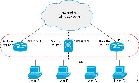
The virtual router does not physically exist but represents the common default router for interfaces that are configured to provide backup to each other. You do not need to configure the hosts on the LAN with the IP address of the active router. Instead, you configure them with the IP address (virtual IP address) of the virtual router as their default router. If the active router fails to send a hello message within the configurable period of time, the standby router takes over, responds to the virtual addresses, and becomes the active router, assuming the active router duties. From the host perspective, the virtual router remains the same.

Note![]() Packets received on a routed port destined for the HSRP virtual IP address will terminate on the local router, regardless of whether that router is the active HSRP router or the standby HSRP router. This includes ping and Telnet traffic. Packets received on a Layer 2 (VLAN) interface destined for the HSRP virtual IP address will terminate on the active router.
Packets received on a routed port destined for the HSRP virtual IP address will terminate on the local router, regardless of whether that router is the active HSRP router or the standby HSRP router. This includes ping and Telnet traffic. Packets received on a Layer 2 (VLAN) interface destined for the HSRP virtual IP address will terminate on the active router.
HSRP for IPv4
HSRP routers communicate with each other by exchanging HSRP hello packets. These packets are sent to the destination IP multicast address 224.0.0.2 (reserved multicast address used to communicate to all routers) on UDP port 1985. The active router sources hello packets from its configured IP address and the HSRP virtual MAC address while the standby router sources hellos from its configured IP address and the interface MAC address, which may or may not be the burned-in address (BIA). The BIA is the last six bytes of the MAC address that is assigned by the manufacturer of the network interface card (NIC).
Because hosts are configured with their default router as the HSRP virtual IP address, hosts must communicate with the MAC address associated with the HSRP virtual IP address. This MAC address is a virtual MAC address, 0000.0C07.ACxy, where xy is the HSRP group number in hexadecimal based on the respective interface. For example, HSRP group 1 uses the HSRP virtual MAC address of 0000.0C07.AC01. Hosts on the adjoining LAN segment use the normal Address Resolution Protocol (ARP) process to resolve the associated MAC addresses.
HSRP version 2 uses the new IP multicast address 224.0.0.102 to send hello packets instead of the multicast address of 224.0.0.2, which is used by version 1. HSRP version 2 permits an expanded group number range of 0 to 4095 and uses a new MAC address range of 0000.0C9F.F000 to 0000.0C9F.FFFF.
HSRP for IPv6
IPv6 hosts learn of available IPv6 routers through IPv6 neighbor discovery (ND) router advertisement (RA) messages. These messages are multicast periodically, or may be solicited by hosts, but the time delay for detecting when a default route is down may be 30 seconds or more. HSRP for IPv6 provides a much faster switchover to an alternate default router than the IPv6 ND protocol provides, less than a second if the milliseconds timers are used. HSRP for IPv6 provides a virtual first hop for IPv6 hosts.
When you configure an IPv6 interface for HSRP, the periodic RAs for the interface link-local address stop after IPv6 ND sends a final RA with a router lifetime of zero. No restrictions occur for the interface IPv6 link-local address. Other protocols continue to receive and send packets to this address.
IPv6 ND sends periodic RAs for the HSRP virtual IPv6 link-local address when the HSRP group is active. These RAs stop after a final RA is sent with a router lifetime of 0 when the HSRP group leaves the active state. HSRP uses the virtual MAC address for active HSRP group messages only (hello, coup, and redesign).
HSRP IPv6 Addresses
An HSRP IPv6 group has a virtual MAC address that is derived from the HSRP group number and a virtual IPv6 link-local address that is derived, by default, from the HSRP virtual MAC address. The default virtual MAC address for an HSRP IPv6 group will always be used to form the virtual IPv6 link-local address, regardless of the actual virtual MAC address used by the group.
Table 5-1 shows the MAC and IP addresses used for IPv6 neighbor discovery packets and HSRP packets.
|
|
|
|
|
|
|---|---|---|---|---|
HSRP does not add IPv6 link-local addresses to the Unicast Routing Information Base (URIB). There are also no secondary virtual IP addresses for link-local addresses.
For global unicast addresses, HSRP will add the virtual IPv6 address to the URIB and IPv6 but will not register the virtual IPv6 addresses to ICMPv6. ICMPv6 redirects are not supported for HSRP IPv6 groups.
HSRP Versions
Cisco NX-OS supports HSRP version 1 by default. You can configure an interface to use HSRP version 2.
HSRP version 2 has the following enhancements to HSRP version 1:
- Expands the group number range. HSRP version 1 supports group numbers from 0 to 255. HSRP version 2 supports group numbers from 0 to 4095.
- For IPv4, uses the IPv4 multicast address 224.0.0.102 or the IPv6 multicast address FF02::66 to send hello packets instead of the multicast address of 224.0.0.2, which is used by HSRP version 1.
- Uses the MAC address range from 0000.0C9F.F000 to 0000.0C9F.FFFF for IPv4 and 0005.73A0.0000 through 0005.73A0.0FFF for IPv6 addresses. HSRP version 1 uses the MAC address range 0000.0C07.AC00 to 0000.0C07.ACFF.
- Adds support for MD5 authentication.
When you change the HSRP version, Cisco NX-OS reinitializes the group because it now has a new virtual MAC address.
HSRP version 2 has a different packet format than HSRP version 1. The packet format uses a type-length-value (TLV) format. HSRP version 2 packets received by an HSRP version 1 router are ignored.
HSRP Authentication
HSRP message digest 5 (MD5) algorithm authentication protects against HSRP-spoofing software and uses the industry-standard MD5 algorithm for improved reliability and security. HSRP includes the IPv4 or IPv6 address in the authentication TLVs.
HSRP and Proxy Address Resolution Protocols
You can use HSRP when the hosts are configured for proxy Address Resolution Protocol (ARP). When you enable HSRP on an interface on which an ARP request is received, the response includes the virtual MAC address. If the HSRP interface is not the active router, then it does not respond (because the active router responds). If you enable multiple HSRP groups on the interface, and the router acts as the active HSRP router for more than one group, then one of the HSRP group's MAC addresses provides the proxy ARP response.
HSRP Messages
Routers that are configured with HSRP exchange the following three types of multicast messages:
- Hello—The hello message conveys the HSRP priority and state information of the router to other HSRP routers.
- Coup—When a standby router wants to assume the function of the active router, it sends a coup message.
- Resign—A router that is the active router sends this message when it is about to shut down or when a router that has a higher priority sends a hello or coup message.
HSRP Load Sharing
HSRP allows you to configure multiple groups on an interface. You can configure two overlapping IPv4 HSRP groups to load share traffic from the connected hosts while providing the default router redundancy expected from HSRP. Figure 5-2 shows an example of a load-sharing HSRP IPv4 configuration.
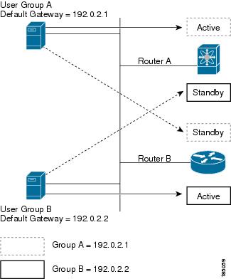
Figure 5-2 shows two routers A and B and two HSRP groups. Router A is the active router for group A but is the standby router for group B. Similarly, router B is the active router for group B and the standby router for group A. If both routers remain active, HSRP load balances the traffic from the hosts across both routers. If either router fails, the remaining router continues to process traffic for both hosts.
Note![]() HSRP for IPv6 load balances by default. If there are two HSRP IPv6 groups on the subnet, then hosts will learn of both from their router advertisements and choose to use one so that the load is shared between the advertised routers.
HSRP for IPv6 load balances by default. If there are two HSRP IPv6 groups on the subnet, then hosts will learn of both from their router advertisements and choose to use one so that the load is shared between the advertised routers.
Object Tracking and HSRP
You can use object tracking to modify the priority of an HSRP interface based on the operational state of another interface. Object tracking allows you to route to a standby router if the interface to the main network fails.
Two objects that you can track are the line protocol state of an interface or the reachability of an IP route. If the specified object goes down, Cisco DC-OS reduces the HSRP priority by the configured amount. For more information, see the “Configuring HSRP Object Tracking” section.
vPC and HSRP
HSRP interoperates with virtual port channels (vPCs). vPCs allow links that are physically connected to two different Cisco Nexus 7000 Series devices to appear as a single port channel by a third device. See the Cisco Nexus 7000 Series NX-OS Layer 2 Switching Configuration Guide, Release 5.x, for more information on vPCs.
vPC forwards traffic through both the active HSRP router and the standby HSRP router. You can configure a threshold on the priority of the standby HSRP router to determine when traffic should fail over to the vPC trunk. See the “Configuring the HSRP Priority” section.
Note![]() You should configure HSRP on the primary vPC peer device as active and HSRP on the vPC secondary device as standby.
You should configure HSRP on the primary vPC peer device as active and HSRP on the vPC secondary device as standby.
BFD
This feature supports bidirectional forwarding detection (BFD). BFD is a detection protocol designed to provide fast forwarding-path failure detection times. BFD provides subsecond failure detection between two adjacent devices and can be less CPU-intensive than protocol hello messages because some of the BFD load can be distributed onto the data plane on supported modules. See the Cisco Nexus 7000 Series NX-OS Interfaces Configuration Guide, Release 5.x, for more information.
High Availability and Extended Nonstop Forwarding
HSRP supports stateful restarts and stateful switchovers. A stateful restart occurs when the HSRP process fails and is restarted. A stateful switchover occurs when the active supervisor switches to the standby supervisor. Cisco NX-OS applies the run-time configuration after the switchover.
If HSRP hold timers are configured for short time periods, these timers may expire during a controlled switchover or in-service software upgrade (ISSU). HSRP supports extended non-stop forwarding (NSF) to temporarily extend these HSRP hold timers during a controlled switchover or in-service software upgrade (ISSU).
With extended NSF configured, HSRP sends hello messages with the extended timers. HSRP peers update their hold timers with these new values. The extended timers prevent unnecessary HSRP state changes during the switchover or ISSU. After the switchover or ISSU event, HSRP restores the hold timers to their original configured values. If the switchover fails, HSRP restores the hold timers after the extended hold timer values expire.
See the “Configuring Extended Hold Timers for HSRP” section for more information.
Virtualization Support
HSRP supports Virtual Routing and Forwarding instances (VRFs). VRFs exist within virtual device contexts (VDCs). By default, Cisco NX-OS places you in the default VDC and default VRF unless you specifically configure another VDC and VRF.
If you change the VRF membership of an interface, Cisco NX-OS removes all Layer 3 configuration, including HSRP.
Licensing Requirements for HSRP
The following table shows the licensing requirements for this feature:
Prerequisites for HSRP
The following prerequisites are required for using this feature on Cisco DCNM. For a full list of feature-specific prerequisites, see the platform-specific documentation.
HSRP has the following prerequisites:
- You must enable the HSRP feature in a device before you can configure and enable any HSRP groups.
- System-message logging levels for the HSRP feature must meet or exceed Cisco DCNM requirements. During device discovery, Cisco DCNM detects inadequate logging levels and raises them to the minimum requirements. Cisco Nexus 7000 Series switches that run Cisco NX-OS Release 4.0 are an exception. For Cisco NX-OS Release 4.0, prior to device discovery, use the command-line interface to configure logging levels to meet or exceed Cisco DCNM requirements. For more information, see the Fundamentals Configuration Guide, Cisco DCNM for LAN, Release 5.x .
- If you configure VDCs, install the Advanced Services license and enter the desired VDC (see the Cisco Nexus 7000 Series NX-OS Virtual Device Context Configuration Guide, Release 5.x).
Guidelines and Limitations
HSRP has the following configuration guidelines and limitations:
- You must configure an IP address for the interface that you configure HSRP on and enable that interface before HSRP becomes active.
- You must configure HSRP version 2 when you configure an IPv6 interface for HSRP.
- For IPv4, the virtual IP address must be in the same subnet as the interface IP address.
- We recommend that you do not configure more than one first-hop redundancy protocol on the same interface.
- Proxy ARP must be disabled when you configure HSRP on same interface.
- HSRP version 2 does not interoperate with HSRP version 1. An interface cannot operate both version 1 and version 2 because both versions are mutually exclusive. However, the different versions can be run on different physical interfaces of the same router.
- You cannot change from version 2 to version 1 if you have configured groups above the group number range allowed for version 1 (0 to 255).
- Cisco NX-OS removes all Layer 3 configuration on an interface when you change the interface VRF membership, port channel membership, or when you change the port mode to Layer 2.
- If you configure virtual MAC addresses with vPC, you must configure the same virtual MAC address on both vPC peers.
- You cannot use the HSRP MAC address burned-in option on a VLAN interface that is a vPC member.
Default Settings
Table 5-2 lists the default settings for HSRP parameters.
|
|
|
|---|---|
Platform Support
The following platform supports this feature. For platform-specific information, including guidelines and limitations, system defaults, and configuration limits, see the corresponding documentation.
|
|
|
|---|---|
Configuring HSRP
You can access HSRP from the Routing feature selection.
For more information about the Cisco Data Center Network Manager features, see the Fundamentals Configuration Guide, Cisco DCNM for LAN, Release 5.x .
This section includes the following topics:
- Enabling the HSRP Feature
- Using the HSRP Template
- Configuring the HSRP Version
- Configuring an HSRP Group for IPv4
- Configuring an HSRP Group for IPv6
- Configuring the HSRP Virtual MAC Address
- Authenticating HSRP
- Configuring Preemption
- Configuring HSRP Object Tracking
- Configuring the HSRP Priority
- Customizing HSRP
- Configuring Extended Hold Timers for HSRP
Note![]() If you are familiar with the Cisco IOS CLI, be aware that the Cisco NX-OS commands for this feature might differ from the Cisco IOS commands that you would use.
If you are familiar with the Cisco IOS CLI, be aware that the Cisco NX-OS commands for this feature might differ from the Cisco IOS commands that you would use.
Enabling the HSRP Feature
You must globally enable the HSRP feature before you can configure and enable any HSRP groups.
BEFORE YOU BEGIN
System-message logging levels for the HSRP feature must meet or exceed Cisco DCNM requirements. During device discovery, Cisco DCNM detects inadequate logging levels and raises them to the minimum requirements. Cisco Nexus 7000 Series switches that run Cisco NX-OS Release 4.0 are an exception. For Cisco NX-OS Release 4.0, prior to device discovery, use the command-line interface to configure logging levels to meet or exceed Cisco DCNM requirements. For more information, see the Fundamentals Configuration Guide, Cisco DCNM for LAN, Release 5.x .
Ensure that you are in the correct VDC (or use the switchto vdc command).
DETAILED STEPS
To enable the HSRP feature in a VDC, use the following command in global configuration mode:
|
|
|
|---|---|
To disable the HSRP feature in a VDC and remove all associated configuration, use the following command in global configuration mode:
|
|
|
|---|---|
Using the HSRP Template
You can use the HSRP template to configure a base set of common parameters that Cisco NX-OS uses across all HSRP groups. You can override these values by configuring the same parameters within an individual HSRP group.
To enter the HSRP template configuration mode, use the following command in global configuration mode:
|
|
|
|---|---|
Configuring the HSRP Version
You can configure the HSRP version. If you change the version for existing groups, Cisco NX-OS reinitializes HSRP for those groups because the virtual MAC address changes. The HSRP version applies to all groups on the interface.
Note![]() IPv6 HSRP groups must be configured as HSRP version 2.
IPv6 HSRP groups must be configured as HSRP version 2.
DETAILED STEPS
Step 1![]() From the Feature Selector pane, choose Routing > Gateway Redundancy > HSRP.
From the Feature Selector pane, choose Routing > Gateway Redundancy > HSRP.
The available devices appear in the Summary pane.
Step 2![]() From the Summary pane, click the device that you want to configure HSRP on.
From the Summary pane, click the device that you want to configure HSRP on.
The system highlights the HSRP row in the Summary pane, and tabs update in the Details pane.
Step 3![]() From the highlighted Interface field, select the interface that you want to configure an HSRP group on from the drop-down list.
From the highlighted Interface field, select the interface that you want to configure an HSRP group on from the drop-down list.
Step 4![]() From the Details pane, click the Interface Settings tab.
From the Details pane, click the Interface Settings tab.
The Interface Settings tab appears.
Step 5![]() From the Interface Settings tab, in the HSRP Version field, enter 1 for HSRP version 1 or enter 2 for HSRP version 2.
From the Interface Settings tab, in the HSRP Version field, enter 1 for HSRP version 1 or enter 2 for HSRP version 2.
Step 6![]() From the menu bar, choose File > Deploy to apply your changes to the device.
From the menu bar, choose File > Deploy to apply your changes to the device.
To configure the HSRP version, use the following command in interface configuration mode:
|
|
|
|---|---|
Configuring an HSRP Group for IPv4
You can configure an HSRP group on an IPv4 interface and configure the virtual IP address and virtual MAC address for the HSRP group.
BEFORE YOU BEGIN
Ensure that you have enabled the HSRP feature (see the “Enabling the HSRP Feature” section).
Cisco NX-OS enables an HSRP group once you configure the virtual IP address on any member interface in the group. You should configure HSRP attributes such as authentication, timers, and priority before you enable the HSRP group.
Ensure that you are in the correct VDC (or use the switchto vdc command).
SUMMARY STEPS
5.![]() ip [ ip-address [ secondary ]]
ip [ ip-address [ secondary ]]
DETAILED STEPS
Step 1![]() From the Feature Selector pane, choose Routing > Gateway Redundancy > HSRP.
From the Feature Selector pane, choose Routing > Gateway Redundancy > HSRP.
The available devices appear in the Summary pane.
Step 2![]() From the Summary pane, click the device that you want to configure HSRP on.
From the Summary pane, click the device that you want to configure HSRP on.
Step 3![]() Right-click and choose New IPv4 GroupSetting.
Right-click and choose New IPv4 GroupSetting.
Step 4![]() From the Interface drop-down list, select the interface or group of interfaces that you want to configure an HSRP group on.
From the Interface drop-down list, select the interface or group of interfaces that you want to configure an HSRP group on.
Step 5![]() From the Group ID field, enter the group number for this group.
From the Group ID field, enter the group number for this group.
Step 6![]() From the Details pane, click the Group Details tab.
From the Details pane, click the Group Details tab.
The Group Details tab appears.
Step 7![]() From the Group Details tab, expand the Group Details section.
From the Group Details tab, expand the Group Details section.
The basic group information appears in the Details pane.
Step 8![]() (Optional) From the Group Name field, enter a name for this HSRP group member.
(Optional) From the Group Name field, enter a name for this HSRP group member.
Step 9![]() (Optional) From the Virtual IP Address Settings Area, check Learn Virtual IP from Members of Group to learn the virtual IP address from another HSRP group member.
(Optional) From the Virtual IP Address Settings Area, check Learn Virtual IP from Members of Group to learn the virtual IP address from another HSRP group member.
Step 10![]() (Optional) From the Virtual IP Address Settings Area, in the Virtual IP Address field, enter an IPv4 address.
(Optional) From the Virtual IP Address Settings Area, in the Virtual IP Address field, enter an IPv4 address.
Step 11![]() (Optional) From the Virtual IP Address Settings Area, in the Secondary IP Address field, enter an IPv4 address for the secondary IP address.
(Optional) From the Virtual IP Address Settings Area, in the Secondary IP Address field, enter an IPv4 address for the secondary IP address.
Step 12![]() From the menu bar, choose File > Deploy to apply your changes to the device.
From the menu bar, choose File > Deploy to apply your changes to the device.
RELATED TOPICS
Note![]() You should use the no shutdown command to enable the interface after you finish the configuration.
You should use the no shutdown command to enable the interface after you finish the configuration.
The following example shows how to configure an HSRP group on Ethernet 1/2:
switch(config)# interface ethernet 1/2
switch(config-if)# ip 192.0.2.2/8
switch(config-if-hsrp)# ip 192.0.2.1
switch(config-if)# no shutdown
switch(config-if)# copy running-config startup-config
Using the HSRP Template
You can use the HSRP template to configure a base set of common parameters that Cisco NX-OS uses across all HSRP groups. You can override these values by configuring the same parameters within an individual HSRP group.
To enter the HSRP template configuration mode, use the following command in global configuration mode:
|
|
|
|---|---|
Configuring an HSRP Group for IPv6
You can configure an HSRP group on an IPv6 interface and configure the virtual MAC address for the HSRP group.
When you configure an HSRP group for IPv6, HSRP generates a link-local address from the link-local prefix. HSRP also generates a modified EUI-64 format interface identifier in which the EUI-64 interface identifier is created from the relevant HSRP virtual MAC address.
BEFORE YOU BEGIN
Ensure that you have enabled the HSRP feature (see the “Enabling the HSRP Feature” section).
Ensure that you have enabled HSRP version 2 on the interface that you want to configure an IPv6 HSRP group on.
Ensure that you have configured HSRP attributes such as authentication, timers, and priority before you enable the HSRP group.
Ensure that you are in the correct VDC (or use the switchto vdc command).
SUMMARY STEPS
3.![]() ipv6 address ipv6-address/length
ipv6 address ipv6-address/length
6.![]() ip ipv6-address
ip ipv6-address
or
ip autoconfig
DETAILED STEPS
Step 1![]() From the Feature Selector pane, choose Routing > Gateway Redundancy > HSRP.
From the Feature Selector pane, choose Routing > Gateway Redundancy > HSRP.
The available devices appear in the Summary pane.
Step 2![]() From the Summary pane, click the device that you want to configure HSRP on.
From the Summary pane, click the device that you want to configure HSRP on.
Step 3![]() Right-click and choose New IPv6 GroupSetting.
Right-click and choose New IPv6 GroupSetting.
Step 4![]() From the Interface drop-down list, select the interface or group of interfaces that you want to configure an HSRP group on.
From the Interface drop-down list, select the interface or group of interfaces that you want to configure an HSRP group on.
Step 5![]() From the Group ID field, enter the group number for this group.
From the Group ID field, enter the group number for this group.
Step 6![]() From the Details pane, click the Group Details tab.
From the Details pane, click the Group Details tab.
The Group Details tab appears.
Step 7![]() From the Group Details tab, expand the Interfaces section.
From the Group Details tab, expand the Interfaces section.
The HSRP interface information appears in the Details pane.
Step 8![]() From the HSRP Version field, enter 2 for HSRP version 2.
From the HSRP Version field, enter 2 for HSRP version 2.
Step 9![]() From the Group Details tab, expand the Group Details section.
From the Group Details tab, expand the Group Details section.
The basic group information appears in the Details pane.
Step 10![]() (Optional) From the Group Name field, enter a name for this HSRP group member.
(Optional) From the Group Name field, enter a name for this HSRP group member.
Step 11![]() (Optional) From the Virtual IP Address Settings Area, check Autoconfigure IP address to configure the virtual IPv6 address from the link-local address and the HSRP virtual MAC address.
(Optional) From the Virtual IP Address Settings Area, check Autoconfigure IP address to configure the virtual IPv6 address from the link-local address and the HSRP virtual MAC address.
Step 12![]() (Optional) From the Virtual IP Address Settings Area, check Learn Virtual IP from Members of Group to learn the virtual IP address from another HSRP group member.
(Optional) From the Virtual IP Address Settings Area, check Learn Virtual IP from Members of Group to learn the virtual IP address from another HSRP group member.
Step 13![]() (Optional) From the Virtual IP Address Settings Area, in the Virtual IPv6 Address field, enter an IPv6 address.
(Optional) From the Virtual IP Address Settings Area, in the Virtual IPv6 Address field, enter an IPv6 address.
Step 14![]() From the menu bar, choose File > Deploy to apply your changes to the device.
From the menu bar, choose File > Deploy to apply your changes to the device.
RELATED TOPICS
Note![]() You should use the no shutdown command to enable the interface after you finish the configuration.
You should use the no shutdown command to enable the interface after you finish the configuration.
The following example shows how to configure an IPv6 HSRP group on Ethernet 3/2:
switch(config)# interface ethernet 3/2
switch(config-if)# ipv6 address 2001:0DB8:0001:0001:/64
switch(config-if)# hsrp 2 ipv6
switch(config-if)# no shutdown
switch(config-if)# copy running-config startup-config
Configuring the HSRP Virtual MAC Address
You can override the default virtual MAC address that HSRP derives from the configured group number.
Note![]() You must configure the same virtual MAC address on both vPC peers of a vPC link.
You must configure the same virtual MAC address on both vPC peers of a vPC link.
DETAILED STEPS
Step 1![]() From the Feature Selector pane, choose Routing > Gateway Redundancy > HSRP.
From the Feature Selector pane, choose Routing > Gateway Redundancy > HSRP.
The available devices appear in the Summary pane.
Step 2![]() From the Summary pane, click the device that you want to configure HSRP on.
From the Summary pane, click the device that you want to configure HSRP on.
The system highlights the HSRP row in the Summary pane, and tabs update in the Details pane.
Step 3![]() From the highlighted Interface field, select the interface that you want to configure an HSRP group on from the drop-down list.
From the highlighted Interface field, select the interface that you want to configure an HSRP group on from the drop-down list.
Step 4![]() From the Details pane, click the Group Details tab.
From the Details pane, click the Group Details tab.
The Group Details tab appears.
Step 5![]() From the Group Details tab, expand the Group Details section.
From the Group Details tab, expand the Group Details section.
The basic group information appears in the Details pane.
Step 6![]() From the Virtual MAC Address field, enter the virtual MAC address.
From the Virtual MAC Address field, enter the virtual MAC address.
The string uses the standard MAC address format (xxxx.xxxx.xxxx).
Step 7![]() From the menu bar, choose File > Deploy to apply your changes to the device.
From the menu bar, choose File > Deploy to apply your changes to the device.
You can configure HSRP to use the burned-in MAC address as the virtual MAC address on an interface.
DETAILED STEPS
Step 1![]() From the Feature Selector pane, choose Routing > Gateway Redundancy > HSRP.
From the Feature Selector pane, choose Routing > Gateway Redundancy > HSRP.
The available devices appear in the Summary pane.
Step 2![]() From the Summary pane, click the device that you want to configure HSRP on.
From the Summary pane, click the device that you want to configure HSRP on.
The system highlights the HSRP row in the Summary pane, and tabs update in the Details pane.
Step 3![]() From the highlighted Interface field, select the interface that you want to configure an HSRP group on from the drop-down list.
From the highlighted Interface field, select the interface that you want to configure an HSRP group on from the drop-down list.
Step 4![]() From the Details pane, click the Interface Settings tab.
From the Details pane, click the Interface Settings tab.
The Interface Settings tab appears.
Step 5![]() From the Interface Settings tab, check Use Burned In Address (use-bia).
From the Interface Settings tab, check Use Burned In Address (use-bia).
Step 6![]() (Optional) To use the burned-in address for all groups, check Apply Use Burned In Address (use-bia) to all Groups.
(Optional) To use the burned-in address for all groups, check Apply Use Burned In Address (use-bia) to all Groups.
Step 7![]() From the menu bar, choose File > Deploy to apply your changes to the device.
From the menu bar, choose File > Deploy to apply your changes to the device.
RELATED TOPICS
To manually configure the virtual MAC address for an HSRP group, use the following command in hsrp configuration mode:
|
|
|
|---|---|
Configures the virtual MAC address for an HSRP group. The string uses the standard MAC address format (xxxx.xxxx.xxxx). |
To configure HSRP to use the burned-in MAC address of the interface for the virtual MAC address, use the following command in interface configuration mode:
Authenticating HSRP
You can configure HSRP to authenticate the protocol using cleartext or MD5 digest authentication. MD5 authentication uses a key chain (see the Cisco Nexus 7000 Series NX-OS Security Configuration Guide, Release 5.x).
BEFORE YOU BEGIN
Ensure that you have enabled the HSRP feature (see the “Enabling the HSRP Feature” section).
You must configure the same authentication and keys on all members of the HSRP group.
Ensure that you have created the key chain if you are using MD5 authentication.
Ensure that you are in the correct VDC (or use the switchto vdc command).
SUMMARY STEPS
2.![]() interface interface- type slot/port
interface interface- type slot/port
3.![]() hsrp group- number [ ipv4 | ipv6 ]
hsrp group- number [ ipv4 | ipv6 ]
authentication md5 { key-chain key-chain | key-string { 0 | 7 } text [ timeout seconds ]}
DETAILED STEPS
Step 1![]() From the Feature Selector pane, choose Routing > Gateway Redundancy > HSRP.
From the Feature Selector pane, choose Routing > Gateway Redundancy > HSRP.
The available devices appear in the Summary pane.
Step 2![]() From the Summary pane, click the device that you want to configure HSRP on.
From the Summary pane, click the device that you want to configure HSRP on.
The system highlights the HSRP row in the Summary pane, and tabs update in the Details pane.
Step 3![]() From the highlighted Interface field, select the interface that you want to configure an HSRP group on from the drop-down list.
From the highlighted Interface field, select the interface that you want to configure an HSRP group on from the drop-down list.
Step 4![]() From the Details pane, click the Group Details tab.
From the Details pane, click the Group Details tab.
The Group Details tab appears.
Step 5![]() From the Group Details tab, expand the Authentication, Router Preemption section.
From the Group Details tab, expand the Authentication, Router Preemption section.
The authentication information appears in the Details pane.
Step 6![]() From the Authentication area, from the Method drop-down list, choose the authentication method.
From the Authentication area, from the Method drop-down list, choose the authentication method.
Step 7![]() (Optional) For text authentication, in the password field, enter the password string.
(Optional) For text authentication, in the password field, enter the password string.
Step 8![]() (Optional) For MD5 authentication, choose either Key or Key Chain.
(Optional) For MD5 authentication, choose either Key or Key Chain.
Step 9![]() (Optional) For the Key option, in the key field, enter the key string, time-out value, and check Encrypted for an encrypted key string.
(Optional) For the Key option, in the key field, enter the key string, time-out value, and check Encrypted for an encrypted key string.
Step 10![]() (Optional) For the Key Chain option, from the key chain drop-down list, choose the key chain that you want to use.
(Optional) For the Key Chain option, from the key chain drop-down list, choose the key chain that you want to use.
Step 11![]() From the menu bar, choose File > Deploy to apply your changes to the device.
From the menu bar, choose File > Deploy to apply your changes to the device.
RELATED TOPICS
The following example shows how to configure MD5 authentication for HSRP on Ethernet 1/2 after creating the key chain:
switch(config-keychain-key)# interface ethernet 1/2
switch(config-if-hsrp)# authenticate md5 key-chain hsrp-keys
switch(config-if-hsrp)# copy running-config startup-config
Configuring Preemption
You can configure HSRP to preempt another active router based on the configured priority.
DETAILED STEPS
Step 1![]() From the Feature Selector pane, choose Routing > Gateway Redundancy > HSRP.
From the Feature Selector pane, choose Routing > Gateway Redundancy > HSRP.
The available devices appear in the Summary pane.
Step 2![]() From the Summary pane, click the device that you want to configure HSRP on.
From the Summary pane, click the device that you want to configure HSRP on.
The system highlights the HSRP row in the Summary pane, and tabs update in the Details pane.
Step 3![]() From the highlighted Interface field, select the interface that you want to configure an HSRP group on from the drop-down list.
From the highlighted Interface field, select the interface that you want to configure an HSRP group on from the drop-down list.
Step 4![]() From the Details pane, click the Group Details tab.
From the Details pane, click the Group Details tab.
The Group Details tab appears.
Step 5![]() From the Group Details tab, expand the Authentication, Router Preemption section.
From the Group Details tab, expand the Authentication, Router Preemption section.
The authentication information appears in the Details pane.
Step 6![]() Check Router Preemption.
Check Router Preemption.
Step 7![]() From the Minimum Delay(sec) field, enter the minimum delay time.
From the Minimum Delay(sec) field, enter the minimum delay time.
Step 8![]() From the Sync Delay(sec) field, enter the sync delay time.
From the Sync Delay(sec) field, enter the sync delay time.
Step 9![]() From the Reload Delay(sec) field, enter the reload delay time.
From the Reload Delay(sec) field, enter the reload delay time.
Step 10![]() From the menu bar, choose File > Deploy to apply your changes to the device.
From the menu bar, choose File > Deploy to apply your changes to the device.
RELATED TOPICS
Configuring HSRP Object Tracking
You can configure an HSRP group to adjust its priority based on the availability of other interfaces or routes. The priority of a device can change dynamically if it has been configured for object tracking and the object that is being tracked goes down.
The tracking process periodically polls the tracked objects and notes any value change. The value change triggers HSRP to recalculate the priority. The HSRP interface with the higher priority becomes the active router if you configure the HSRP interface for preemption. For more information on object tracking, see the “Configuring Preemption” section.
DETAILED STEPS
Step 1![]() From the Feature Selector pane, choose Routing > Gateway Redundancy > HSRP.
From the Feature Selector pane, choose Routing > Gateway Redundancy > HSRP.
The available devices appear in the Summary pane.
Step 2![]() From the Summary pane, click the device that you want to configure HSRP on.
From the Summary pane, click the device that you want to configure HSRP on.
The system highlights the HSRP row in the Summary pane, and tabs update in the Details pane.
Step 3![]() From the highlighted Interface field, select the interface that you want to configure an HSRP group on from the drop-down list.
From the highlighted Interface field, select the interface that you want to configure an HSRP group on from the drop-down list.
Step 4![]() From the Details pane, click the Group Details tab.
From the Details pane, click the Group Details tab.
The Group Details tab appears.
Step 5![]() From the Group Details tab, expand the Object Tracking section.
From the Group Details tab, expand the Object Tracking section.
The object tracking information appears in the Details pane.
Step 6![]() Right-click and choose Add Track Object.
Right-click and choose Add Track Object.
Step 7![]() From the object ID drop-down list, choose the object ID that you want to use to modify the HSRP priority value with.
From the object ID drop-down list, choose the object ID that you want to use to modify the HSRP priority value with.
Step 8![]() In the Decrement field, enter the value that you want to decrement the HSRP priority with if the tracked object state goes down.
In the Decrement field, enter the value that you want to decrement the HSRP priority with if the tracked object state goes down.
Step 9![]() From the menu bar, choose File > Deploy to apply your changes to the device.
From the menu bar, choose File > Deploy to apply your changes to the device.
RELATED TOPICS
The following example shows how to configure HSRP object tracking on Ethernet 1/2:
switch(config)# track 1 interface ethernet 2/2 line-protocol
switch(config)# interface ethernet 1/2
switch(config-if-hsrp)# track 1 decrement 20
switch(config-if-hsrp)# copy running-config startup-config
Configuring the HSRP Priority
You can configure the HSRP priority on an interface. HSRP uses the priority to determine which HSRP group member acts as the active router. If you configure HSRP on a vPC-enabled interface, you can optionally configure the upper and lower threshold values to control when to fail over to the vPC trunk If the standby router priority falls below the lower threshold, HSRP sends all standby router traffic across the vPC trunk to forward through the active HSRP router. HSRP maintains this scenario until the standby HSRP router priority increases above the upper threshold.
For IPv6 HSRP groups, if all group members have the same priority, HSRP selects the active router based on the IPv6 link-local address.
DETAILED STEPS
To configure the HSRP priority, use the following command in interface configuration mode:
Step 1![]() From the Feature Selector pane, choose Routing > Gateway Redundancy > HSRP.
From the Feature Selector pane, choose Routing > Gateway Redundancy > HSRP.
The available devices appear in the Summary pane.
Step 2![]() From the Summary pane, click the device that you want to configure the HSRP priority on.
From the Summary pane, click the device that you want to configure the HSRP priority on.
The system highlights the HSRP row in the Summary pane, and tabs update in the Details pane.
Step 3![]() From the highlighted Interface field, select the interface that you want to configure the HSRP priority on from the drop-down list.
From the highlighted Interface field, select the interface that you want to configure the HSRP priority on from the drop-down list.
Step 4![]() From the Details pane, click the Group Details tab.
From the Details pane, click the Group Details tab.
The Group Details tab appears.
Step 5![]() From the Group Details tab, expand the Group Details section.
From the Group Details tab, expand the Group Details section.
The basic group information appears in the Details pane.
Step 6![]() (Optional) From the Configured Priority field, enter the priority for this HSRP group member.
(Optional) From the Configured Priority field, enter the priority for this HSRP group member.
The range is from 1 to 255. The default is 100.
Step 7![]() (Optional) Check Forwarding Threshold and set the upper and lower threshold values used by vPC to determine when to fail over to the vPC trunk.
(Optional) Check Forwarding Threshold and set the upper and lower threshold values used by vPC to determine when to fail over to the vPC trunk.
The range is from 1 to 255. The lower threshold default is 1. The upper threshold default is 100.
Step 8![]() From the menu bar, choose File > Deploy to apply your changes to the device.
From the menu bar, choose File > Deploy to apply your changes to the device.
RELATED TOPICS
Customizing HSRP
You can optionally customize the behavior of HSRP. Be aware that as soon as you enable an HSRP group by configuring a virtual IP address, that group is now operational. If you first enable an HSRP group before customizing HSRP, the router could take control over the group and become the active router before you finish customizing the feature. If you plan to customize HSRP, you should do so before you enable the HSRP group.
DETAILED STEPS
Step 1![]() From the Feature Selector pane, choose Routing > Gateway Redundancy > HSRP.
From the Feature Selector pane, choose Routing > Gateway Redundancy > HSRP.
The available devices appear in the Summary pane.
Step 2![]() From the Summary pane, click the device that you want to configure HSRP on.
From the Summary pane, click the device that you want to configure HSRP on.
The system highlights the HSRP row in the Summary pane, and tabs update in the Details pane.
Step 3![]() From the highlighted Interface field, select the interface that you want to configure an HSRP group on from the drop-down list.
From the highlighted Interface field, select the interface that you want to configure an HSRP group on from the drop-down list.
Step 4![]() From the Details pane, click the Group Details tab.
From the Details pane, click the Group Details tab.
The Group Details tab appears.
Step 5![]() From the Group Details tab, expand the Timers section.
From the Group Details tab, expand the Timers section.
The HSRP timers information appears in the Details pane.
Step 6![]() From the Configured Timers area, in the Hello Time field, enter the hello time.
From the Configured Timers area, in the Hello Time field, enter the hello time.
Step 7![]() Choose sec or msec from the drop-down list.
Choose sec or msec from the drop-down list.
Step 8![]() From the Configured Timers area, in the Hold Time field, enter the hold time.
From the Configured Timers area, in the Hold Time field, enter the hold time.
Step 9![]() Choose sec or msec from the drop-down list.
Choose sec or msec from the drop-down list.
Step 10![]() From the menu bar, choose File > Deploy to apply your changes to the device.
From the menu bar, choose File > Deploy to apply your changes to the device.
RELATED TOPICS
To customize HSRP, use the following commands in hsrp configuration mode:
To customize HSRP, use the following commands in interface configuration mode:
Configuring Extended Hold Timers for HSRP
You can configure HSRP to use extended hold timers to support extended NSF during a controlled (graceful) switchover or ISSU, including software upgrades and supervisor switchovers.You should configure extended hold timers on all HSRP routers (see the “High Availability and Extended Nonstop Forwarding” section).
Note![]() You must configure extended hold timers on all HSRP routers if you configure extended hold timers. If you configure a nondefault hold timer, you should configure the same value on all HSRP routers when you configure HSRP extended hold timers.
You must configure extended hold timers on all HSRP routers if you configure extended hold timers. If you configure a nondefault hold timer, you should configure the same value on all HSRP routers when you configure HSRP extended hold timers.
Note![]() HSRP extended hold timers are not applied if you configure millisecond HSRP hello and hold timers.
HSRP extended hold timers are not applied if you configure millisecond HSRP hello and hold timers.
To configure HSRP extended hold timers, use the following command in global configuration mode:
|
|
|
|---|---|
Sets the HSRP extended hold timer, in seconds. The timer range is from 10 to 255. The default is 10. |
Use the show hsrp command or the show running-config hsrp command to display the extended hold time.
Verifying the HSRP Configuration
To display HSRP configuration information, perform one of the following tasks:
Configuration Examples for HSRP
The following example shows how to enable HSRP on an interface with MD5 authentication and interface tracking:
track 2 interface ethernet 2/2 ip
Field Descriptions for HSRP
This section includes the following field descriptions for HSRP:
- HSRP: Group Details Tab: Group Details Section
- HSRP: Group Details Tab: Authentication, Router Preemption Section
- HSRP: Group Details Tab: Timers Section
- HSRP: Group Details Tab: Object Tracking Section
- HSRP: Interface Settings Tab
HSRP: Group Details Tab: Group Details Section
HSRP: Group Details Tab: Authentication, Router Preemption Section
HSRP: Group Details Tab: Timers Section
|
|
|
|---|---|
|
|
|
|
|
|
HSRP: Group Details Tab: Object Tracking Section
|
|
|
|---|---|
Value to decrement the HSRP group priority if tracked object status is down. |
HSRP: Interface Settings Tab
Additional References
For additional information related to implementing HSRP, see the following sections:
Related Documents
|
|
|
|---|---|
Cisco Nexus 7000 Series NX-OS Unicast Routing Command Reference |
|
Cisco Nexus 7000 Series NX-OS High Availability and Redundancy Guide, Release 5.x |
MIBs
|
|
|
|---|---|
To locate and download MIBs, go to the following URL: http://www.cisco.com/public/sw-center/netmgmt/cmtk/mibs.shtml |
Feature History for HSRP
Table 5-8 lists the release history for this feature.
 Feedback