Unicast Routing Configuration Guide, Cisco DCNM for LAN, Release 7.x
Bias-Free Language
The documentation set for this product strives to use bias-free language. For the purposes of this documentation set, bias-free is defined as language that does not imply discrimination based on age, disability, gender, racial identity, ethnic identity, sexual orientation, socioeconomic status, and intersectionality. Exceptions may be present in the documentation due to language that is hardcoded in the user interfaces of the product software, language used based on RFP documentation, or language that is used by a referenced third-party product. Learn more about how Cisco is using Inclusive Language.
- Updated:
- May 13, 2015
Chapter: Configuring GLBP
- Information About GLBP
- Licensing Requirements for GLBP
- Prerequisites for GLBP
- Guidelines and Limitations
- Default Settings
- Platform Support
- Configuring GLBP
- Verifying the GLBP Configuration
- Configuration Examples for GLBP
- Field Descriptions for GLBP
- GLBP: Group Details Tab: Group Details Section
- GLBP: Group Details Tab: Authentication, Gateway Preemption Section
- GLBP: Group Details Tab: Weighting and Object Tracking Section
- GLBP: Group Details Tab: Virtual Forwarder Setting Section
- GLBP: Group Details Tab: Timers Section
- GLBP: Virtual Gateways and Forwarders Tab: Forwarder Details Section
- GLBP: Virtual Gateways and Forwarders Tab: GLBP Group Member Details Section
- Additional References
- Feature History for GLBP
Configuring GLBP
This chapter describes how to configure the Gateway Load Balancing Protocol (GLBP) on the Cisco Data Center Network Manager (DCNM)NX-OS device.
Information About GLBP
GLBP provides path redundancy for IP by sharing protocol and Media Access Control (MAC) addresses between redundant gateways. Additionally, GLBP allows a group of Layer 3 routers to share the load of the default gateway on a LAN. A GLBP router can automatically assume the forwarding function of another router in the group if the other router fails.
This section includes the following topics:
- GLBP Overview
- GLBP Active Virtual Gateway
- GLBP Virtual MAC Address Assignment
- GLBP Virtual Gateway Redundancy
- GLBP Virtual Forwarder Redundancy
- GLBP Authentication
- GLBP Load Balancing and Tracking
- High Availability and Extended Non-Stop Forwarding
- Virtualization Support
GLBP Overview
GLBP provides automatic gateway backup for IP hosts configured with a single default gateway on an IEEE 802.3 LAN. Multiple routers on the LAN combine to offer a single virtual first-hop IP gateway while sharing the IP packet forwarding load. Other routers on the LAN may act as redundant GLBP gateways that become active if any of the existing forwarding gateways fail.
GLBP performs a similar function to the Hot Standby Redundancy Protocol (HSRP) and the Virtual Router Redundancy Protocol (VRRP). HSRP and VRRP allow multiple routers to participate in a virtual group configured with a virtual IP address. These protocols elect one member as the active router to forward packets to the virtual IP address for the group. The other routers in the group are redundant until the active router fails.
GLBP performs an additional load balancing function that the other protocols do not provide. GLBP load balances over multiple routers (gateways) using a single virtual IP address and multiple virtual MAC addresses. GLBP shares the forwarding load among all routers in a GLBP group instead of allowing a single router to handle the whole load while the other routers remain idle. You configure each host with the same virtual IP address, and all routers in the virtual group participate in forwarding packets. GLBP members communicate between each other using periodic hello messages.
GLBP Active Virtual Gateway
GLBP prioritizes gateways to elect an active virtual gateway ( AVG). If multiple gateways have the same priority, the gateway with the highest real IP address becomes the AVG. The AVG assigns a virtual MAC address to each member of the GLBP group. Each member is the active virtual forwarder ( AVF) for its assigned virtual MAC address, forwarding packets sent to its assigned virtual MAC address.
The AVG also answers Address Resolution Protocol (ARP) requests for the virtual IP address. Load sharing is achieved when the AVG replies to the ARP requests with different virtual MAC addresses.

Note![]() Packets received on a routed port destined for the GLBP virtual IP address will terminate on the local router, regardless of whether that router is the active GLBP router or a redundant GLBP router. This includes ping and Telnet traffic. Packets received on a Layer 2 (VLAN) interface destined for the GLBP virtual IP address will terminate on the active router.
Packets received on a routed port destined for the GLBP virtual IP address will terminate on the local router, regardless of whether that router is the active GLBP router or a redundant GLBP router. This includes ping and Telnet traffic. Packets received on a Layer 2 (VLAN) interface destined for the GLBP virtual IP address will terminate on the active router.
GLBP Virtual MAC Address Assignment
The AVG assigns the virtual MAC addresses to each member of the group. The group members request a virtual MAC address after they discover the AVG through hello messages. The AVG assigns the next MAC address based on the load-balancing algorithm selected (see the “GLBP Load Balancing and Tracking” section). A gateway that is assigned with a virtual MAC address by the AVG is the primary virtual forwarder. The other members of the GLBP group that learn the virtual MAC addresses from hello messages are secondary virtual forwarders.
GLBP Virtual Gateway Redundancy
GLBP provides virtual gateway redundancy. A member in a group can be in the active, standby, or listen state. GLBP uses a priority algorithm to elect one gateway as the AVG and elect another gateway as the standby virtual gateway. The remaining gateways go into the listen state. You can configure the GLBP priority on each gateway. If the GLBP priority is identical on multiple gateways, GLBP uses the gateway with the highest IP address as the AVG.
If an AVG fails, the standby virtual gateway assumes responsibility for the virtual IP address. GLBP elects a new standby virtual gateway from the gateways in the listen state.
GLBP Virtual Forwarder Redundancy
GLBP provides virtual forwarder redundancy. Virtual forwarder redundancy is similar to virtual gateway redundancy with an active virtual forwarder (AVF). If the AVF fails, a secondary virtual forwarder in the listen state assumes responsibility for the virtual MAC address. This secondary virtual forwarder is also a primary virtual forwarder for a different virtual MAC address. GLBP migrates hosts away from the old virtual MAC address of the failed AVF, using the following two timers:
- Redirect timer—Specifies the interval during which the AVG continues to redirect hosts to the old virtual MAC address. When the redirect time expires, the AVG stops using the old virtual MAC address in ARP replies, although the secondary virtual forwarder continues to forward packets that were sent to the old virtual MAC address.
- Secondary hold timer—Specifies the interval during which the virtual MAC address is valid. When the secondary hold time expires, GLBP removes the virtual MAC address from all gateways in the GLBP group and load balances the traffic over the remaining AVFs. The expired virtual MAC address becomes eligible for reassignment by the AVG.
GLBP uses hello messages to communicate the current state of the timers.
In Figure 4-1, router A is the AVG for a GLBP group and is responsible for the virtual IP address 192.0.2.1. Router A is also an AVF for the virtual MAC address 0007.b400.0101. Router B is a member of the same GLBP group and is designated as the AVF for the virtual MAC address 0007.b400.0102. Client 1 has a default gateway IP address of 192.0.2.1, the virtual IP address, and a gateway MAC address of 0007.b400.0101 that points to router A. Client 2 shares the same default gateway IP address but receives the gateway MAC address 0007.b400.0102 because router B is sharing the traffic load with router A.
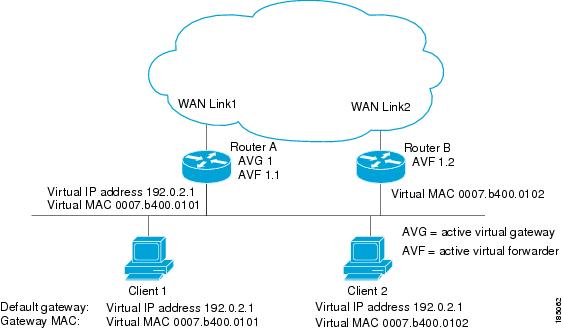
If router A becomes unavailable, client 1 does not lose access to the WAN because router B assumes responsibility for forwarding packets sent to the virtual MAC address of router A and for responding to packets sent to its own virtual MAC address. Router B also assumes the role of the AVG for the entire GLBP group. Communication for the GLBP members continues despite the failure of a router in the GLBP group.
GLBP Authentication
GLBP has three authentication types:
MD5 authentication provides greater security than plain text authentication. MD5 authentication allows each GLBP group member to use a secret key to generate a keyed MD5 hash that is part of the outgoing packet. At the receiving end, a keyed hash of an incoming packet is generated. If the hash within the incoming packet does not match the generated hash, the packet is ignored. The key for the MD5 hash can either be given directly in the configuration using a key string or supplied indirectly through a key chain.
You can also choose to use a simple password in plain text to authenticate GLBP packets or choose no authentication for GLBP.
GLBP Load Balancing and Tracking
You can configure the following load-balancing methods for GLBP:
- Round-robin—GLBP cycles through the virtual MAC addresses sent in ARP replies, load balancing the traffic across all the AVFs.
- Weighted—AVG uses the advertised weight for an AVF to decide the load directed to the AVF. A higher weight means that the AVG directs more traffic to the AVF.
- Host dependent—GLBP uses the MAC address of the host to determine which virtual MAC address to direct the host to use. This algorithm guarantees that a host gets the same virtual MAC address if the number of virtual forwarders does not change.
The default for IPv4 networks is round-robin. You can disable all load balancing for GLBP on an interface. If you do not configure load balancing, the AVG handles all traffic for the hosts while the other GLBP group members are in standby or listen mode.
You can configure GLBP to track an interface or routes and enable the secondary virtual forwarder to take over if a tracked link goes down. GLBP tracking uses weighted load-balancing to determine whether a GLBP group member acts as an AVF. You must configure the initial weighting values and optional thresholds to enable or disable this group member as an AVF. You can also configure the interface to track and the value that will reduce the interface’s weighting if the interface goes down. When the GLBP group weighting drops below the lower threshold, the member is no longer an AVF and a secondary virtual forwarder takes over. When the weighting rises above the upper threshold, the member can resume its role as an AVF.
Figure 4-2 shows an example of GLBP tracking and weighting.
Figure 4-2 GLBP Object Tracking and Weighting
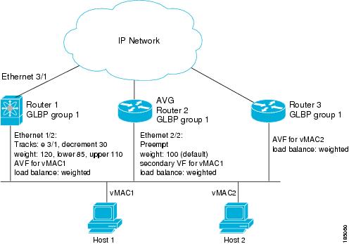
In Figure 4-2, the Ethernet 1/2 interface on router 1 is the gateway for host 1 (the AVF for virtual MAC address, vMAC1), while Ethernet 2/2 on router 2 acts as a secondary virtual forwarder for Host 1. Ethernet 1/2 tracks Ethernet 3/1, which is the network connection for router 1. If Ethernet 3/1 goes down, the weighting for Ethernet 1/2 drops to 90. Ethernet 2/2 on router 2 preempts Ethernet 1/2 and takes over as AVF because it has the default weighting of 100 and is configured to preempt the AVF.
See the “Configuring GLBP Weighting and Tracking” section for details about configuring weighting and tracking.
High Availability and Extended Non-Stop Forwarding
GLBP supports stateful restarts and stateful switchover. A stateful restart occurs when the GLBP process fails and is restarted. A stateful switchover occurs when the active supervisor switches to the standby supervisor. Cisco NX-OS applies the run-time configuration after the switchover.
If GLBP hold timers are configured for short time periods, these timers may expire during a controlled switchover or in-service software upgrade (ISSU). GLBP supports extended non-stop forwarding (NSF) to temporarily extend these GLBP hold timers during a controlled switchover or in-service software upgrade (ISSU).
With extended NSF configured, GLBP sends hello messages with the extended timers. GLBP peers update their hold timers with these new values. The extended timers prevent unnecessary GLBP state changes during the switchover or ISSU. After the switchover or ISSU event, GLBP restores the hold timers to their original configured values. If the switchover fails, GLBP restores the hold timers after the extended hold timer values expire.
See the “Configuring Extended Hold Timers for GLBP” section for more information.
Virtualization Support
GLBP supports Virtual Routing and Forwarding instances (VRFs). VRFs exist within virtual device contexts (VDCs). By default, Cisco NX-OS places you in the default VDC and default VRF unless you specifically configure another VDC and VRF.
If you change the VRF membership of an interface, Cisco NX-OS removes all Layer 3 configuration, including GLBP.
Licensing Requirements for GLBP
The following table shows the licensing requirements for this feature:
Prerequisites for GLBP
The following prerequisites are required for using this feature on Cisco DCNM. For a full list of feature-specific prerequisites, see the platform-specific documentation.
GLBP has the following prerequisites:
- Globally enable the GLBP feature (see the “Enabling the GLBP Feature” section).
- System-message logging levels for the GLBP feature must meet or exceed Cisco DCNM requirements. During device discovery, Cisco DCNM detects inadequate logging levels and raises them to the minimum requirements. Cisco Nexus 7000 Series switches that run Cisco NX-OS Release 4.0 are an exception. For Cisco NX-OS Release 4.0, prior to device discovery, use the command-line interface to configure logging levels to meet or exceed Cisco DCNM requirements. For more information, see the Fundamentals Configuration Guide, Cisco DCNM for LAN, Release 5.x .
- You can only configure GLBP on Layer 3 interfaces (see the Cisco Nexus 7000 Series NX-OS Interfaces Configuration Guide, Release 5.x, and the Interfaces Configuration Guide, Cisco DCNM for LAN, Release 6.x).
- If you configure VDCs, install the Advanced Services license and enter the desired VDC (see the Cisco Nexus 7000 Series NX-OS Virtual Device Context Configuration Guide, Release 5.x).
Guidelines and Limitations
GLBP has the following configuration guidelines and limitations:
- You should configure all customization options for GLBP on all GLBP member gateways before enabling a GLBP group by configuring a virtual IP address.
- You must configure an IP address for the interface that you configure GLBP on and enable that interface before GLBP becomes active.
- The GLBP virtual IP address must be in the same subnet as the interface IP address.
- We recommend that you do not configure more than one first-hop redundancy protocol on the same interface.
- Cisco NX-OS removes all layer 3 configuration on an interface when you change the VDC, interface VRF membership, port channel membership, or when you change the port mode to layer 2.
- Cisco NX-OS does not support GLBP group configuration on interface secondary subnets.
Default Settings
Table 4-1 lists the default settings for GLBP parameters.
|
|
|
|---|---|
Platform Support
The following platform supports this feature. For platform-specific information, including guidelines and limitations, system defaults, and configuration limits, see the corresponding documentation.
|
|
|
|---|---|
Configuring GLBP
You can access GLBP from the Routing feature selection.
For more information about the Data Center Network Manager features, see the Fundamentals Configuration Guide, Cisco DCNM for LAN, Release 5.x .
This section includes the following topics:
- Enabling the GLBP Feature
- Creating a GLBP Group
- Configuring GLBP Authentication
- Configuring GLBP Load Balancing
- Configuring GLBP Weighting and Tracking
- Configuring Extended Hold Timers for GLBP
- Configuring Gateway Preemption
- Customizing GLBP
- Enabling a GLBP Group
Note![]() If you are familiar with the Cisco IOS CLI, be aware that the Cisco NX-OS commands for this feature might differ from the Cisco IOS commands that you would use.
If you are familiar with the Cisco IOS CLI, be aware that the Cisco NX-OS commands for this feature might differ from the Cisco IOS commands that you would use.
Enabling the GLBP Feature
You must enable the GLBP feature before you can configure and enable any GLBP groups.
BEFORE YOU BEGIN
System-message logging levels for the GLBP feature must meet or exceed Cisco DCNM requirements. During device discovery, Cisco DCNM detects inadequate logging levels and raises them to the minimum requirements. Cisco Nexus 7000 Series switches that run Cisco NX-OS Release 4.0 are an exception. For Cisco NX-OS Release 4.0, prior to device discovery, use the command-line interface to configure logging levels to meet or exceed Cisco DCNM requirements. For more information, see the Fundamentals Configuration Guide, Cisco DCNM for LAN, Release 5.x .
Ensure that you are in the correct VDC (or use the switchto vdc command).
DETAILED STEPS
To enable the GLBP feature, use the following command in global configuration mode:
|
|
|
|---|---|
To disable the GLBP feature in a VDC and remove all associated configuration, use the following command in global configuration mode:
|
|
|
|---|---|
Creating a GLBP Group
DETAILED STEPS
Step 1![]() From the Feature Selector pane, choose Routing > Gateway Redundancy > GLBP.
From the Feature Selector pane, choose Routing > Gateway Redundancy > GLBP.
The available devices appear in the Summary pane.
Step 2![]() From the Summary pane, click the device that you want to configure GLBP on.
From the Summary pane, click the device that you want to configure GLBP on.
Step 3![]() From the menu bar, choose Actions > New GroupSetting.
From the menu bar, choose Actions > New GroupSetting.
The system highlights the new GLBP row in the Summary pane, and tabs update in the Details pane.
Step 4![]() From the highlighted Interface field, select the interface that you want to configure a GLBP group on from the drop-down list.
From the highlighted Interface field, select the interface that you want to configure a GLBP group on from the drop-down list.
Step 5![]() From the Group ID field, enter the group number for this group.
From the Group ID field, enter the group number for this group.
The system creates the new group on the device and highlights the new GLBP group in the Summary pane, and tabs update in the Details pane.
Step 6![]() From the Details pane, click the Group Details tab.
From the Details pane, click the Group Details tab.
The Group Details tab appears.
Step 7![]() From the Group Details tab, expand the Group Details section.
From the Group Details tab, expand the Group Details section.
The basic group information appears in the Details pane.
Step 8![]() (Optional) From the Priority field, enter the priority for this GLBP group member.
(Optional) From the Priority field, enter the priority for this GLBP group member.
Step 9![]() (Optional) From the Group Name field, enter a name for this GLBP group member.
(Optional) From the Group Name field, enter a name for this GLBP group member.
Step 10![]() From the menu bar, choose File > Deploy to apply your changes to the device.
From the menu bar, choose File > Deploy to apply your changes to the device.
RELATED TOPICS
Configuring GLBP Authentication
You can configure GLBP to authenticate the protocol using cleartext or an MD5 digest. MD5 authentication uses a key chain (see the Cisco Nexus 7000 Series NX-OS Security Configuration Guide, Release 5.x Security Configuration Guide, Cisco DCNM for LAN, Release 6.x).
BEFORE YOU BEGIN
Ensure that you are in the correct VDC (or use the switchto vdc command).
Enable the GLBP feature (see the “Enabling the GLBP Feature” section).
Note![]() You must configure the same authentication and keys on all members of the GLBP group.
You must configure the same authentication and keys on all members of the GLBP group.
SUMMARY STEPS
2.![]() interface interface- type slot/port
interface interface- type slot/port
authentication md5 { key-chain key-chain | key-string { text | encrypted text }
6.![]() ip [ ip-address [ secondary ]]
ip [ ip-address [ secondary ]]
DETAILED STEPS
Step 1![]() From the Feature Selector pane, choose Routing > Gateway Redundancy > GLBP.
From the Feature Selector pane, choose Routing > Gateway Redundancy > GLBP.
The available devices appear in the Summary pane.
Step 2![]() From the Summary pane, click the device that you want to configure GLBP on.
From the Summary pane, click the device that you want to configure GLBP on.
Step 3![]() Click the group that you want to configure authentication on.
Click the group that you want to configure authentication on.
Step 4![]() From the Details pane, click the Group Details tab.
From the Details pane, click the Group Details tab.
The Group Details tab appears.
Step 5![]() From the Group Details tab, expand the Authentication, Gateway Preemption section.
From the Group Details tab, expand the Authentication, Gateway Preemption section.
The authentication information appears in the Details pane.
Step 6![]() From the Authentication area, from the Method drop-down list, choose the authentication method.
From the Authentication area, from the Method drop-down list, choose the authentication method.
Step 7![]() (Optional) For text authentication, in the password field, enter the password string.
(Optional) For text authentication, in the password field, enter the password string.
Step 8![]() (Optional) For MD5 authentication, check either Key or Key Chain.
(Optional) For MD5 authentication, check either Key or Key Chain.
Step 9![]() (Optional) For the Key option, in the key field, enter the key string and check encrypted for an encrypted key string.
(Optional) For the Key option, in the key field, enter the key string and check encrypted for an encrypted key string.
Step 10![]() (Optional) For the Key Chain option, from the key chain drop-down list, choose the key chain that you want to use.
(Optional) For the Key Chain option, from the key chain drop-down list, choose the key chain that you want to use.
Step 11![]() From the menu bar, choose File > Deploy to apply your changes to the device.
From the menu bar, choose File > Deploy to apply your changes to the device.
RELATED TOPICS
The following example shows how to configure MD5 authentication for GLBP on Ethernet 1/2 after creating the key chain:
switch(config)# interface ethernet 1/2
switch(config-if-glbp)# authenticate md5 key-chain glbp-keys
switch(config-if-glbp)# copy running-config startup-config
Configuring GLBP Load Balancing
You can configure GLBP to use load balancing based on round-robin, weighted, or host-dependent methods (see the “GLBP Load Balancing and Tracking” section).
DETAILED STEPS
Step 1![]() From the Feature Selector pane, choose Routing > Gateway Redundancy > GLBP.
From the Feature Selector pane, choose Routing > Gateway Redundancy > GLBP.
The available devices appear in the Summary pane.
Step 2![]() From the Summary pane, click the device that you want to configure GLBP on.
From the Summary pane, click the device that you want to configure GLBP on.
Step 3![]() Click the group that you want to configure load balancing on.
Click the group that you want to configure load balancing on.
Step 4![]() From the Details pane, click the Group Details tab.
From the Details pane, click the Group Details tab.
The Group Details tab appears.
Step 5![]() From the Group Details tab, expand the Group Details section.
From the Group Details tab, expand the Group Details section.
The basic group information appears in the Details pane.
Step 6![]() From the Method drop-down list, choose the load-balancing method.
From the Method drop-down list, choose the load-balancing method.
Step 7![]() From the menu bar, choose File > Deploy to apply your changes to the device.
From the menu bar, choose File > Deploy to apply your changes to the device.
RELATED TOPICS
To configure GLBP load balancing, use the following command in GLBP configuration mode:
|
|
|
|---|---|
Sets the GLBP load-balancing method. The default is round-robin. |
Configuring GLBP Weighting and Tracking
You can configure GLBP weighting values and object tracking to work with the GLBP weighted load-balancing method.
You can optionally configure the interface to preempt an active virtual forwarder (AVF) if the interface was originally assigned with the virtual MAC address or if this interface has a higher weight than the AVF.
BEFORE YOU BEGIN
Ensure that you have configured the object tracking entry that you want to use to modify GLBP weighting (see the “Configuring Object Tracking” section).
Ensure that you are in the correct VDC (or use the switchto vdc command).
Enable the GLBP feature (see the “Enabling the GLBP Feature” section).
SUMMARY STEPS
2.![]() track object- id interface interface-type number { ip routing | line-protocol }
track object- id interface interface-type number { ip routing | line-protocol }
3.![]() track object- id ip route ip-prefix/length reachability
track object- id ip route ip-prefix/length reachability
4.![]() interface interface- type slot/port
interface interface- type slot/port
7.![]() weighting maximum [ lower lower ] [ upper upper ]
weighting maximum [ lower lower ] [ upper upper ]
8.![]() weighting track object-number [ decrement value ]
weighting track object-number [ decrement value ]
9.![]() forwarder preempt [ delay minimum seconds ]
forwarder preempt [ delay minimum seconds ]
10.![]() ip [ ip-address [ secondary ]]
ip [ ip-address [ secondary ]]
DETAILED STEPS
Step 1![]() From the Feature Selector pane, choose Routing > Gateway Redundancy > GLBP.
From the Feature Selector pane, choose Routing > Gateway Redundancy > GLBP.
The available devices appear in the Summary pane.
Step 2![]() From the Summary pane, click the device that you want to configure GLBP on.
From the Summary pane, click the device that you want to configure GLBP on.
Step 3![]() Click the group that you want to configure weighting and tracking on.
Click the group that you want to configure weighting and tracking on.
Step 4![]() From the Details pane, click the Group Details tab.
From the Details pane, click the Group Details tab.
The Group Details tab appears.
Step 5![]() From the Group Details tab, expand the Weighting and Object Tracking section.
From the Group Details tab, expand the Weighting and Object Tracking section.
The weighting and object tracking information appears in the Details pane.
Step 6![]() From the Weight area, enter the maximum, lower threshold, and upper threshold weighting values.
From the Weight area, enter the maximum, lower threshold, and upper threshold weighting values.
Step 7![]() From the GLBP Tracking area, right-click and choose Add TrackObject from the pop-up menu.
From the GLBP Tracking area, right-click and choose Add TrackObject from the pop-up menu.
Step 8![]() From the object ID drop-down list, choose the object ID that you want to use to modify the GLBP weighting value with.
From the object ID drop-down list, choose the object ID that you want to use to modify the GLBP weighting value with.
Step 9![]() In the Weight Decrement field, enter the value that you want to decrement the GLBP weighting with if the tracked object state goes down.
In the Weight Decrement field, enter the value that you want to decrement the GLBP weighting with if the tracked object state goes down.
Step 10![]() (Optional) From the Group Details tab, expand the Virtual Forwarder Setting section.
(Optional) From the Group Details tab, expand the Virtual Forwarder Setting section.
The virtual forwarders information appears in the Details pane.
Step 11![]() (Optional) Check Virtual Forwarder Preemption.
(Optional) Check Virtual Forwarder Preemption.
Step 12![]() (Optional) In the Preemption Delay field, enter the delay value in seconds.
(Optional) In the Preemption Delay field, enter the delay value in seconds.
Step 13![]() From the menu bar, choose File > Deploy to apply your changes to the device.
From the menu bar, choose File > Deploy to apply your changes to the device.
RELATED TOPICS
The following example shows how to configure GLBP weighting and tracking on Ethernet 1/2:
switch(config)# track 2 interface ethernet 2/2 ip routing
switch(config)# interface ethernet 1/2
switch(config-if-glbp)# weighting 110 lower 95 upper 105
switch(config-if-glbp)# weighting track 2 decrement 20
switch(config-if-glbp)# copy running-config startup-config
Configuring Gateway Preemption
DETAILED STEPS
Step 1![]() From the Feature Selector pane, choose Routing > Gateway Redundancy > GLBP.
From the Feature Selector pane, choose Routing > Gateway Redundancy > GLBP.
The available devices appear in the Summary pane.
Step 2![]() From the Summary pane, click the device that you want to configure GLBP on.
From the Summary pane, click the device that you want to configure GLBP on.
Step 3![]() Click the group that you want to configure authentication on.
Click the group that you want to configure authentication on.
Step 4![]() From the Details pane, click the Group Details tab.
From the Details pane, click the Group Details tab.
The Group Details tab appears.
Step 5![]() From the Group Details tab, expand the Authentication, Gateway Preemption section.
From the Group Details tab, expand the Authentication, Gateway Preemption section.
The preemption information appears in the Details pane.
Step 6![]() From the Authentication, Gateway Preemption section, check Gateway Preemption.
From the Authentication, Gateway Preemption section, check Gateway Preemption.
Step 7![]() From the Minimum Delay field, enter the minimum delay to wait before preemption occurs.
From the Minimum Delay field, enter the minimum delay to wait before preemption occurs.
Step 8![]() From the menu bar, choose File > Deploy to apply your changes to the device.
From the menu bar, choose File > Deploy to apply your changes to the device.
RELATED TOPICS
Customizing GLBP
Customizing the behavior of GLBP is optional. Be aware that as soon as you enable a GLBP group by configuring a virtual IP address, that group is operational. If you enable a GLBP group before you customize GLBP, the router could take over control of the group and become the AVG before you finish customizing the feature. If you plan to customize GLBP, you should do so before enabling GLBP.
DETAILED STEPS
Step 1![]() From the Feature Selector pane, choose Routing > Gateway Redundancy > GLBP.
From the Feature Selector pane, choose Routing > Gateway Redundancy > GLBP.
The available devices appear in the Summary pane.
Step 2![]() From the Summary pane, click the device that you want to configure GLBP on.
From the Summary pane, click the device that you want to configure GLBP on.
Step 3![]() Click the group that you want to configure timers on.
Click the group that you want to configure timers on.
Step 4![]() From the Details pane, click the Group Details tab.
From the Details pane, click the Group Details tab.
The Group Details tab appears.
Step 5![]() From the Group Details tab, expand the Timers section.
From the Group Details tab, expand the Timers section.
The timers information appears in the Details pane.
Step 6![]() From the Configured Timers area, in the Hello Time (msec) field, enter the hello time.
From the Configured Timers area, in the Hello Time (msec) field, enter the hello time.
Step 7![]() From the Configured Timers area, in the Hold Time (msec) field, enter the hold time.
From the Configured Timers area, in the Hold Time (msec) field, enter the hold time.
Step 8![]() From the Configured Timers area, in the Redirect Time (sec) field, enter the redirect time.
From the Configured Timers area, in the Redirect Time (sec) field, enter the redirect time.
Step 9![]() From the Configured Timers area, in the Forwarder Time-out (sec) field, enter the hold time.
From the Configured Timers area, in the Forwarder Time-out (sec) field, enter the hold time.
Step 10![]() From the menu bar, choose File > Deploy to apply your changes to the device.
From the menu bar, choose File > Deploy to apply your changes to the device.
RELATED TOPICS
To customize GLBP, use the following commands in GLBP configuration mode:
Configuring Extended Hold Timers for GLBP
You can configure GLBP to use extended hold timers to support extended NSF during a controlled switchover or ISSU. You should configure extended hold timers on all GLBP gateways. (see the “High Availability and Extended Non-Stop Forwarding” section).
Note![]() You must configure extended hold timers on all GLBP gateways if you configure extended hold timers. You can configure different extended holdtimer values on each GLBP gateway, based on the expected system switchover delays.
You must configure extended hold timers on all GLBP gateways if you configure extended hold timers. You can configure different extended holdtimer values on each GLBP gateway, based on the expected system switchover delays.
Note![]() If you configure a non-default hold timer, you should configure the same value on all GLBP gateways when you configure GLBP extended hold timers.
If you configure a non-default hold timer, you should configure the same value on all GLBP gateways when you configure GLBP extended hold timers.
To configure GLBP extended hold timers, use the following command in global configuration mode:
|
|
|
|---|---|
Sets the GLBP extended hold timer, in seconds. The timer range is from 10 to 255. The default is 10. |
Use the show glbp command or the show running-config glbp command to display the extended hold time.
Enabling a GLBP Group
You can configure the virtual IP address on an interface to enable the GLBP group. You must configure each gateway in the GLBP group with the same group number. The GLBP member can learn all other required parameters from another GLBP member.
DETAILED STEPS
Step 1![]() From the Feature Selector pane, choose Routing > Gateway Redundancy > GLBP.
From the Feature Selector pane, choose Routing > Gateway Redundancy > GLBP.
The available devices appear in the Summary pane.
Step 2![]() From the Summary pane, click the device that you want to configure GLBP on.
From the Summary pane, click the device that you want to configure GLBP on.
Step 3![]() Click the group that you want to configure timers on.
Click the group that you want to configure timers on.
Step 4![]() From the Details pane, click the Group Details tab.
From the Details pane, click the Group Details tab.
The Group Details tab appears.
Step 5![]() From the Group Details tab, expand the Group Details section.
From the Group Details tab, expand the Group Details section.
The general information appears in the Details pane.
Step 6![]() (Optional) To manually set the virtual IP address, enter an IP address in the Virtual IP address field.
(Optional) To manually set the virtual IP address, enter an IP address in the Virtual IP address field.
Step 7![]() (Optional) To learn the virtual IP address, check Learn Virtual IP from Members Of Group.
(Optional) To learn the virtual IP address, check Learn Virtual IP from Members Of Group.
Step 8![]() (Optional) From the Virtual Secondary IP Address field, enter a secondary IP address.
(Optional) From the Virtual Secondary IP Address field, enter a secondary IP address.
Step 9![]() From the menu bar, choose File > Deploy to apply your changes to the device.
From the menu bar, choose File > Deploy to apply your changes to the device.
RELATED TOPICS
The following example shows how to enable GLBP on Ethernet 1/2:
Verifying the GLBP Configuration
To display GLBP configuration information, perform one of the following tasks:
Configuration Examples for GLBP
The following example enables GLBP on an interface, with MD5 authentication, interface tracking, and weighted load balancing:
track 2 interface ethernet 2/2 ip
authentication md5 key-chain glbp-keys
weighting 110 lower 95 upper 105
weighting track 2 decrement 20
Field Descriptions for GLBP
This section includes the following field descriptions for GLBP:
- GLBP: Group Details Tab: Group Details Section
- GLBP: Group Details Tab: Authentication, Gateway Preemption Section
- GLBP: Group Details Tab: Weighting and Object Tracking Section
- GLBP: Group Details Tab: Virtual Forwarder Setting Section
- GLBP: Group Details Tab: Timers Section
- GLBP: Virtual Gateways and Forwarders Tab: Forwarder Details Section
- GLBP: Virtual Gateways and Forwarders Tab: GLBP Group Member Details Section
GLBP: Group Details Tab: Group Details Section
|
|
|
|---|---|
|
|
|
Display only. Number of times the GLBP gateway state changed. |
|
|
|
|
|
|
|
|
|
|
GLBP: Group Details Tab: Authentication, Gateway Preemption Section
|
|
|
|---|---|
|
|
|
|
|
|
GLBP: Group Details Tab: Weighting and Object Tracking Section
|
|
|
|---|---|
|
|
|
|
|
|
Value to decrement the GLBP weight if the tracked object goes down. |
|
GLBP: Group Details Tab: Virtual Forwarder Setting Section
|
|
|
|---|---|
Device that takes over as the AVF for a GLBP group if the current AVF for a GLBP group falls below its low weighting threshold. |
|
GLBP: Group Details Tab: Timers Section
GLBP: Virtual Gateways and Forwarders Tab: Forwarder Details Section
|
|
|
|---|---|
Display only. Number of times the GLBP gateway state changed. |
|
GLBP: Virtual Gateways and Forwarders Tab: GLBP Group Member Details Section
|
|
|
|---|---|
Additional References
For additional information related to implementing GLBP, see the following sections:
Related Documents
|
|
|
|---|---|
Cisco Nexus 7000 Series NX-OS Unicast Routing Command Reference |
|
Cisco Nexus 7000 Series NX-OS High Availability and Redundancy Guide, Release 5.x |
Standards
|
|
|
|---|---|
No new or modified standards are supported by this feature, and support for existing standards has not been modified by this feature. |
Feature History for GLBP
Table 4-9 lists the release history for this feature.
|
|
|
|
|---|---|---|
Added support for extended hold timers for extended NSF support. |
||
 Feedback