- New and Changed Information for the Interfaces NX-OS Configuration Guide
- Preface
- Overview
- Configuring Basic Interface Parameters
- Configuring Layer 2 Interfaces
- Configuring Layer 3 Interfaces
- Configuring Bidirectional Forwarding Detection
- Configuring Port Channels
- Configuring vPCs
- Configuring IP Tunnels
- Configuring Q-in-Q VLAN Tunnels
- IETF RFCs Supported by Cisco NX-OS Interfaces
- Configuration Limits for Cisco NX-OS Interfaces
- Information About Port Channels
- Licensing Requirements for Port Channeling
- Prerequisites for Port Channeling
- Guidelines and Limitations
- Default Settings
- Configuring Port Channels
- Creating a Port Channel
- Adding a Layer 2 Port to a Port Channel
- Adding a Layer 3 Port to a Port Channel
- Configuring the Bandwidth and Delay for Informational Purposes
- Shutting Down and Restarting the Port-Channel Interface
- Configuring a Port-Channel Description
- Configuring the Speed and Duplex Settings for a Port-Channel Interface
- Configuring Flow Control
- Configuring Load Balancing Using Port Channels
- Enabling LACP
- Configuring LACP Port-Channel Port Modes
- Configuring LACP Port-Channel MinLinks
- Configuring the LACP Port-Channel MaxBundle
- Configuring the LACP Fast Timer Rate
- Configuring the LACP System Priority
- Configuring the LACP Port Priority
- Disabling LACP Graceful Convergence
- Disabling LACP Suspend Individual
- Reenabling LACP Suspend Individual
- Verifying the Port-Channel Configuration
- Monitoring the Port-Channel Interface Configuration
- Example Configurations for Port Channels
- Additional References
- Feature History for Configuring Port Channels
Configuring Port Channels
This chapter describes how to configure port channels and to apply and configure the Link Aggregation Control Protocol (LACP) for more efficient use of port channels in the Cisco NX-OS devices.
Beginning with Cisco Release NX-OS 5.1(1), you can use any of the F1 series modules or M1 series modules for the port channel, but you cannot combine member ports on an F1 module with ports on an M1 module in a single port channel. On a single switch, the port-channel compatibility parameters must be the same among all the port-channel members on the physical switch.
This chapter includes the following sections:
- Information About Port Channels
- Licensing Requirements for Port Channeling
- Prerequisites for Port Channeling
- Guidelines and Limitations
- Default Settings
- Configuring Port Channels
- Verifying the Port-Channel Configuration
- Monitoring the Port-Channel Interface Configuration
- Example Configurations for Port Channels
- Additional References
- Feature History for Configuring Port Channels
Information About Port Channels
A port channel is an aggregation of multiple physical interfaces that creates a logical interface. You can bundle up to 8 individual active links into a port channel to provide increased bandwidth and redundancy. Port channeling also load balances traffic on the M series module and across these physical interfaces. The port channel stays operational as long as at least one physical interface within the port channel is operational.

Note![]() Beginning with Cisco NX-OS Release 5.1, you can bundle up to 16 active links into a port channel on the F Series module.
Beginning with Cisco NX-OS Release 5.1, you can bundle up to 16 active links into a port channel on the F Series module.
You cannot configure a shared interface to be part of a port channel. See the Cisco NX-OS FCoE Configuration Guide for Cisco Nexus 7000 and Cisco MDS 9500 for more information on shared interfaces.
You can create a Layer 2 port channel by bundling compatible Layer 2 interfaces, or you can create Layer 3 port channels by bundling compatible Layer 3 interfaces. After you create a Layer 3 port channel, you can add an IP address to the port-channel interface and create subinterfaces on the Layer 3 port channel. You cannot combine Layer 2 and Layer 3 interfaces in the same port channel.
Beginning in Cisco NX-OS Release 4.2, you can apply port security to port channels. See the Cisco Nexus 7000 Series NX-OS Security Configuration Guide, Release 5.x, for information on port security.
All ports in the port channel must be in the same virtual device context (VDC); you cannot configure port channels across VDCs.
You can also change the port channel from Layer 3 to Layer 2. See “Configuring Layer 2 Interfaces,” for information on creating Layer 2 interfaces.
Any configuration changes that you apply to the port channel are applied to each member interface of that port channel. For example, if you configure Spanning Tree Protocol (STP) parameters on the port channel, the Cisco NX-OS software applies those parameters to each interface in the port channel.
Note![]() After a Layer 2 port becomes part of a port channel, all switchport configurations must be done on the port channel; you can no longer apply switchport configurations to individual port-channel members. You cannot apply Layer 3 configurations to an individual port-channel member either; you must apply the configuration to the entire port channel.
After a Layer 2 port becomes part of a port channel, all switchport configurations must be done on the port channel; you can no longer apply switchport configurations to individual port-channel members. You cannot apply Layer 3 configurations to an individual port-channel member either; you must apply the configuration to the entire port channel.
You can create subinterfaces on a Layer 3 port channel, even though a subinterface is part of the logical port-channel interface. See the “Subinterfaces” section for more information on port-channel subinterfaces.
You can use static port channels, with no associated aggregation protocol, for a simplified configuration.
For more flexibility, you can use the Link Aggregation Control Protocol (LACP), which is defined in IEEE 802.3ad. When you use LACP, the link passes protocol packets. You cannot configure LACP on shared interfaces.
See the “LACP Overview” section for information on LACP.
This section includes the following topics:
- Port Channels
- Port-Channel Interfaces
- Basic Settings
- Compatibility Requirements
- Load Balancing Using Port Channels
- LACP
- Virtualization Support
- High Availability
Port Channels
A port channel bundles physical links into a channel group to create a single logical link that provides the aggregate bandwidth of up to 8 physical links on the M series module. If a member port within a port channel fails, the traffic previously carried over the failed link switches to the remaining member ports within the port channel.
Note![]() Beginning with Cisco NX-OS Release 5.1, you can bundle up to 16 active ports simultaneously into a port channel on the F Series module.
Beginning with Cisco NX-OS Release 5.1, you can bundle up to 16 active ports simultaneously into a port channel on the F Series module.
You can bundle up to 8 ports into a static port channel without using any aggregation protocol. On the M Series module, you can bundle up to 8 active and 8 standby on the M Series module and up to 16 ports on the F Series module.
However, you can enable the LACP to use port channels more flexibly. Configuring port channels with LACP and static port channels require a slightly different procedure (see the “Configuring Port Channels” section).
Note![]() The device does not support Port Aggregation Protocol (PAgP) for port channels.
The device does not support Port Aggregation Protocol (PAgP) for port channels.
Each port can be in only one port channel. All the ports in a port channel must be compatible; they must use the same speed and duplex mode (see the “Compatibility Requirements” section). When you run static port channels with no aggregation protocol, the physical links are all in the on channel mode; you cannot change this mode without enabling LACP (see the “Port-Channel Modes” section).
You can create port channels directly by creating the port-channel interface, or you can create a channel group that acts to aggregate individual ports into a bundle. When you associate an interface with a channel group, the software creates a matching port channel automatically if the port channel does not already exist. In this instance, the port channel assumes the Layer 2 or Layer 3 configuration of the first interface. You can also create the port channel first. In this instance, the Cisco NX-OS software creates an empty channel group with the same channel number as the port channel and takes the default Layer 2 or Layer 3 configuration, as well as the compatibility configuration (see the “Compatibility Requirements” section). See “Configuring Layer 3 Interfaces,” for more information on creating and deleting port-channel subinterfaces.
Note![]() The port channel is operationally up when at least one of the member ports is up and that port’s status is channeling. The port channel is operationally down when all member ports are operationally down.
The port channel is operationally up when at least one of the member ports is up and that port’s status is channeling. The port channel is operationally down when all member ports are operationally down.
Port-Channel Interfaces
Figure 6-1 shows port-channel interfaces.
Figure 6-1 Port-Channel Interfaces

You can classify port-channel interfaces as Layer 2 or Layer 3 interfaces. In addition, you can configure Layer 2 port channels in either access or trunk mode. Layer 3 port-channel interfaces have routed ports as channel members and may have subinterfaces.
Beginning with Cisco NX-OS Release 4.2(1), you can configure a Layer 3 port channel with a static MAC address. If you do not configure this value, the Layer 3 port channel uses the router MAC of the first channel member to come up. See the Cisco Nexus 7000 Series NX-OS Layer 2 Switching Configuration Guide, Release 5.x, for information on configuring static MAC addresses on Layer 3 port channels.
See “Configuring Layer 2 Interfaces,” for information on configuring Layer 2 ports in access or trunk mode and “Configuring Layer 3 Interfaces,” for information on configuring Layer 3 interfaces and subinterfaces.
Basic Settings
You can configure the following basic settings for the port-channel interface
- Bandwidth—Use this setting for informational purposes only; this setting is to be used by higher-level protocols.
- Delay—Use this setting for informational purposes only; this setting is to be used by higher-level protocols.
- Description
- Duplex
- Flow control.
- IP addresses—Both IPv4 and IPv6
- Maximum Transmission Unit (MTU)
- Shutdown
- Speed
Compatibility Requirements
When you add an interface to a channel group, the software checks certain interface attributes to ensure that the interface is compatible with the channel group. For example, you cannot add a Layer 3 interface to a Layer 2 channel group. The Cisco NX-OS software also checks a number of operational attributes for an interface before allowing that interface to participate in the port-channel aggregation.
The compatibility check includes the following operational attributes:
- Network layer
- (Link) speed capability
- Speed configuration
- Duplex capability
- Duplex configuration
- Port mode
- Access VLAN
- Trunk native VLAN
- Tagged or untagged
- Allowed VLAN list
- MTU size
- SPAN—cannot be a SPAN source or a destination port
- Layer 3 ports—cannot have subinterfaces
- Storm control
- Flow-control capability
- Flow-control configuration
Use the show port-channel compatibility-parameters command to see the full list of compatibility checks that the Cisco NX-OS uses.
You can only add interfaces configured with the channel mode set to on to static port channels, and you can only add interfaces configured with the channel mode as active or passive to port channels that are running LACP. You can configure these attributes on an individual member port. If you configure a member port with an incompatible attribute, the software suspends that port in the port channel.
Alternatively, you can force ports with incompatible parameters to join the port channel if the following parameters are the same:
- (Link) speed capability
- Speed configuration
- Duplex capability
- Duplex configuration
- Flow-control capability
- Flow-control configuration
When the interface joins a port channel, some of its individual parameters are removed and replaced with the values on the port channel as follows:
- Bandwidth
- Delay
- Extended Authentication Protocol over UDP
- VRF
- IP address (v4 and v6)
- MAC address
- Spanning Tree Protocol
- NAC
- Service policy
- Access control lists (ACLs)
Many interface parameters remain unaffected when the interface joins or leaves a port channel as follows:
If you configure subinterfaces for the port-channel interface and remove a member port from the port channel, the configuration of the port-channel subinterface does not propagate to the member ports.
Note![]() When you delete the port channel, the software sets all member interfaces as if they were removed from the port channel.
When you delete the port channel, the software sets all member interfaces as if they were removed from the port channel.
See the “LACP Marker Responders” section for information on port-channel modes.
Load Balancing Using Port Channels
The Cisco NX-OS software load balances traffic across all operational interfaces in a port channel by hashing the addresses in the frame to a numerical value that selects one of the links in the channel. Port channels provide load balancing by default. Port-channel load-balancing uses MAC addresses, IP addresses, or Layer 4 port numbers to select the link. Port-channel load balancing uses either source or destination addresses or ports, or both source and destination addresses or ports.
You can configure the load-balancing mode to apply to all port channels that are configured on the entire device or on specified modules. The per-module configuration takes precedence over the load-balancing configuration for the entire device. You can configure one load-balancing mode for the entire device, a different mode for specified modules, and another mode for the other specified modules. You cannot configure the load-balancing method per port channel.
You can configure the type of load-balancing algorithm used. You can choose the load-balancing algorithm that determines which member port to select for egress traffic by looking at the fields in the frame.
Note![]() The default load-balancing mode for Layer 3 interfaces is the source and destination IP address, and the default load-balancing mode for non-IP interfaces is the source and destination MAC address.
The default load-balancing mode for Layer 3 interfaces is the source and destination IP address, and the default load-balancing mode for non-IP interfaces is the source and destination MAC address.
Note![]() You can configure the device to use one of the following methods to load balance across the port channel:
You can configure the device to use one of the following methods to load balance across the port channel:
- Destination MAC address
- Source MAC address
- Source and destination MAC address
- Destination IP address
- Source IP address
- Source and destination IP address
- Source TCP/UDP port number
- Destination TCP/UDP port number
- Source and destination TCP/UDP port number
Non-IP and Layer 3 port channels both follow the configured load-balancing method, using the source, destination, or source and destination parameters. For example, when you configure load balancing to use the source IP address, all non-IP traffic uses the source MAC address to load balance the traffic while the Layer 3 traffic load balances the traffic using the source IP address. Similarly, when you configure the destination MAC address as the load-balancing method, all Layer 3 traffic uses the destination IP address while the non-IP traffic load balances using the destination MAC address.
Note![]() You cannot configure load balancing using port channels per VDC. You must be in the default VDC to configure this feature; if you attempt to configure this feature from another VDC, the system displays an error.
You cannot configure load balancing using port channels per VDC. You must be in the default VDC to configure this feature; if you attempt to configure this feature from another VDC, the system displays an error.
You can configure load balancing either by the entire system or by specific modules, regardless of the VDC. The port-channel load-balancing is a global setting across all VDCs.
If the ingress traffic is Multiprotocol Label Switching (MPLS) traffic, the software looks under the labels for the IP address on the packet.
The load-balancing algorithms that use port channels do not apply to multicast traffic. Regardless of the load-balancing algorithm you have configured, multicast traffic uses the following methods for load balancing with port channels:
- Multicast traffic with Layer 4 information—Source IP address, source port, destination IP address, destination port
- Multicast traffic without Layer 4 information—Source IP address, destination IP address
- Non-IP multicast traffic—Source MAC address, destination MAC address
Note![]() Devices that run Cisco IOS were able to optimize the behavior of the member ports ASICs if a failure of a single member occurred by running the port-channel hash-distribution command. The Cisco Nexus 7000 Series device performs this optimization by default and does not require or support this command. Cisco NX-OS does support the customization of the load-balancing criteria on port channels through the port-channel load-balance command, either for the entire device or on a per-module basis. See the Cisco Nexus 7000 Series NX-OS Interfaces Command Reference, Release 5.x, for information on this command.
Devices that run Cisco IOS were able to optimize the behavior of the member ports ASICs if a failure of a single member occurred by running the port-channel hash-distribution command. The Cisco Nexus 7000 Series device performs this optimization by default and does not require or support this command. Cisco NX-OS does support the customization of the load-balancing criteria on port channels through the port-channel load-balance command, either for the entire device or on a per-module basis. See the Cisco Nexus 7000 Series NX-OS Interfaces Command Reference, Release 5.x, for information on this command.
LACP
LACP allows you to configure up to 16 interfaces into a port channel. A maximum of 8 interfaces can be active, and a maximum of 8 interfaces can be placed in a standby state on the M Series modules.
Beginning with Cisco NX-OS Release 5.1, you can bundle up to 16 active links into a port channel on the F Series module.
LACP Overview
Note![]() You must enable LACP before you can use LACP. By default, LACP is disabled.
You must enable LACP before you can use LACP. By default, LACP is disabled.
See the “Enabling LACP” section for information on enabling LACP.
Beginning in Cisco NX-OS Release 4.2, the system automatically takes a checkpoint before disabling the feature, and you can roll back to this checkpoint. See the Cisco Nexus 7000 Series NX-OS System Management Configuration Guide, Release 5.x, for information on rollbacks and checkpoints.
Figure 6-2 shows how individual links can be combined into LACP port channels and channel groups as well as function as individual links.
Figure 6-2 Individual Links Combined into a Port Channel
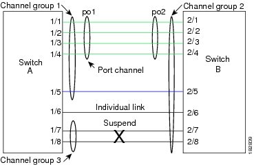
With LACP, you can bundle up to 16 interfaces in a channel group. If the channel group has more than 8 interfaces, the remaining interfaces are in hot standby for the port channel associated with this channel group on the M Series modules.
Beginning with Cisco NX-OS Release 5.1, you can bundle up to 16 active links into a port channel on the F Series module.
Note![]() When you delete the port channel, the software automatically deletes the associated channel group. All member interfaces revert to their original configuration.
When you delete the port channel, the software automatically deletes the associated channel group. All member interfaces revert to their original configuration.
You cannot disable LACP while any LACP configurations are present.
Port-Channel Modes
Individual interfaces in port channels are configured with channel modes. When you run static port channels with no aggregation protocol, the channel mode is always set to on.
After you enable LACP globally on the device, you enable LACP for each channel by setting the channel mode for each interface to active or passive. You can configure either channel mode for individual links in the LACP channel group when you are adding the links to the channel group.
Note![]() You must enable LACP globally before you can configure an interface in either the active or passive channel mode.
You must enable LACP globally before you can configure an interface in either the active or passive channel mode.
Table 6-1 describes the channel modes.
Both the passive and active modes allow LACP to negotiate between ports to determine if they can form a port channel based on criteria such as the port speed and the trunking state.The passive mode is useful when you do not know whether the remote system, or partner, supports LACP.
Ports can form an LACP port channel when they are in different LACP modes if the modes are compatible as in the following examples:
- A port in active mode can form a port channel successfully with another port that is in active mode.
- A port in active mode can form a port channel with another port in passive mode.
- A port in passive mode cannot form a port channel with another port that is also in passive mode, because neither port will initiate negotiation.
- A port in on mode is not running LACP and cannot form a port channel with another port that is in active or passive mode.
LACP ID Parameters
This section describes the LACP parameters in the following topics:
LACP System Priority
Each system that runs LACP has an LACP system priority value. You can accept the default value of 32768 for this parameter, or you can configure a value between 1 and 65535. LACP uses the system priority with the MAC address to form the system ID and also uses the system priority during negotiation with other devices. A higher system priority value means a lower priority.
The system ID is different for each VDC.
Note![]() The LACP system ID is the combination of the LACP system priority value and the MAC address.
The LACP system ID is the combination of the LACP system priority value and the MAC address.
LACP Port Priority
Each port that is configured to use LACP has an LACP port priority. You can accept the default value of 32768 for the LACP port priority, or you can configure a value between 1 and 65535. LACP uses the port priority with the port number to form the port identifier.
LACP uses the port priority to decide which ports should be put in standby mode when there is a limitation that prevents all compatible ports from aggregating and which ports should be put into active mode. A higher port priority value means a lower priority for LACP. You can configure the port priority so that specified ports have a lower priority for LACP and are most likely to be chosen as active links, rather than hot-standby links.
LACP Administrative Key
LACP automatically configures an administrative key value equal to the channel-group number on each port configured to use LACP. The administrative key defines the ability of a port to aggregate with other ports. A port’s ability to aggregate with other ports is determined by these factors:
LACP Marker Responders
You can dynamically redistribute the data traffic by using port channels. This redistribution may result from a removed or added link or a change in the load-balancing scheme. Traffic redistribution that occurs in the middle of a traffic flow can cause misordered frames.
LACP uses the Marker Protocol to ensure that frames are not duplicated or reordered due to this redistribution. The Marker Protocol detects when all the frames of a given traffic flow are successfully received at the remote end. LACP sends Marker PDUs on each of the port-channel links. The remote system responds to the Marker PDU once it receives all the frames received on this link prior to the Marker PDU. The remote system then sends a Marker Responder. Once the Marker Responders are received by the local system on all member links of the port channel, the local system can redistribute the frames in the traffic flow with no chance of misordering. The software supports only Marker Responders.
LACP-Enabled and Static Port Channels Differences
Table 6-2 summarizes the major differences between port channels with LACP enabled and static port channels.
|
|
|
|
|---|---|---|
LACP Compatibility Enhancements
Several new commands have been added in Release 4.2(3) to address interoperability issues and to assist with faster LACP protocol convergence.
When the Cisco Nexus 7000 Series device is connected to a non-Nexus peer, its graceful failover defaults may delay the time taken for a disabled port to be brought down or cause traffic from the peer to be lost. To address these conditions, the lacp graceful-convergence command was added.
By default, LACP sets a port to the suspended state if it does not receive an LACP PDU from the peer. In some cases, although this feature helps in preventing loops created due to misconfigurations, it can cause servers to fail to boot up because they require LACP to logically bring up the port. You can put a port into an individual state by using the lacp suspend-individual command.
LACP Port-Channel MinLinks and MaxBundle
A port channel aggregates similar ports to provide increased bandwidth in a single manageable interface.
With the Cisco NX-OS Release 5.1, the introduction of the minlinks and maxbundle feature further refines LACP port-channel operation and provides increased bandwidth in one manageable interface.
The LACP port-channel MinLink feature does the following:
- Configures the minimum number of ports that must be linked up and bundled in the LACP port channel.
- Prevents the low-bandwidth LACP port channel from becoming active.
- Causes the LACP port channel to become inactive if there are few active members ports to supply the required minimum bandwidth.
The LACP MaxBundle defines the maximum number of bundled ports allowed in a LACP port channel.
The LACP MaxBundle feature does the following:
- Defines an upper limit on the number of bundled ports in an LACP port channel.
- Allows hot-standby ports with fewer bundled ports. (For example, in an LACP port channel with five ports, you can designate two of those ports as hot-standby ports.)
Note![]() The minlink and maxbundle feature works only with LACP port channels. However, the device allows you to configure this feature in non-LACP port channels, but the feature is not operational.
The minlink and maxbundle feature works only with LACP port channels. However, the device allows you to configure this feature in non-LACP port channels, but the feature is not operational.
LACP Offload to Fabric Extenders
To reduce the load on the control plane of the Cisco Nexus 7000 Series device, Cisco NX-OS provides the ability to offload link-level protocol processing to the Fabric Extender CPU. This is supported by LACP by default as soon as there is at least one LACP port-channel configured on a fabric extender.
LACP Fast Timers
You can change the LACP timer rate to modify the duration of the LACP timeout. Use the lacp rate command to set the rate at which LACP control packets are sent to an LACP-supported interface. You can change the timeout rate from the default rate (30 seconds) to the fast rate (1 second). This command is supported only on LACP-enabled interfaces. To configure the LACP fast time rate, see Configuring the LACP Fast Timer Rate.
ISSU and stateful switchover cannot be guaranteed with LACP fast timers.
Virtualization Support
You must configure the member ports and other port channel-related configuration from the virtual device context (VDC) that contains the port channel and member ports. You can use the numbers from 1 to 4096 in each VDC to number the port channels and you can reuse these port channel numbers in different VDCs. For example, you can configure port channel 100 in VDC1 and also configure a different port channel 100 in VDC2.
However, the LACP system ID is different for each VDC. For more information on LACP, see the “LACP Overview” section.
Note![]() See the Cisco Nexus 7000 Series NX-OS Virtual Device Context Configuration Guide, Release 5.x, for complete information on VDCs and assigning resources.
See the Cisco Nexus 7000 Series NX-OS Virtual Device Context Configuration Guide, Release 5.x, for complete information on VDCs and assigning resources.
All ports in one port channel must be in the same VDC. When you are using LACP, all possible 8 active ports and all possible 8 standby ports must be in the same VDC. The port channels can originate in one VDC (with all ports in that channel in the same VDC) and partner with a port channel in another VDC (again, all ports in that channel must be in that VDC).
Note![]() The port-channeling load-balancing mode works either for a single module or across the entire device. You must configure load balancing using port channels in the default VDC. You cannot configure load balancing using port channels within specified VDCs. See the “Load Balancing Using Port Channels” section for more information on load balancing.
The port-channeling load-balancing mode works either for a single module or across the entire device. You must configure load balancing using port channels in the default VDC. You cannot configure load balancing using port channels within specified VDCs. See the “Load Balancing Using Port Channels” section for more information on load balancing.
High Availability
Port channels provide high availability by load balancing traffic across multiple ports. If a physical port fails, the port channel is still operational if there is an active member in the port channel. You can bundle ports from different modules and create a port channel that remains operational even if a module fails because the settings are common across the module.
Port channels support stateful and stateless restarts. A stateful restart occurs on a supervisor switchover. After the switchover, the Cisco NX-OS software applies the runtime configuration after the switchover.
Beginning with Cisco NX-OS Release 5.1, the port channel goes down if the operational ports fall below the configured minlink number.
Note![]() See the Cisco Nexus 7000 Series NX-OS High Availability and Redundancy Guide, Release 5.x, for complete information on high-availability features.
See the Cisco Nexus 7000 Series NX-OS High Availability and Redundancy Guide, Release 5.x, for complete information on high-availability features.
Licensing Requirements for Port Channeling
The following table shows the licensing requirements for this feature:
Prerequisites for Port Channeling
Port channeling has the following prerequisites:
- You must be logged onto the device.
- If necessary, install the Advanced Services license and enter the desired VDC.
- All ports in the channel group must be in the same VDC.
- All ports for a single port channel must be either Layer 2 or Layer 3 ports.
- All ports for a single port channel must meet the compatibility requirements. See the “Compatibility Requirements” section for more information on the compatibility requirements.
- You must configure load balancing from the default VDC.
Guidelines and Limitations
Port channeling has the following configuration guidelines and limitations:
- You must enable LACP before you can use that feature.
- You can configure multiple port channels on a device.
- Do not put shared and dedicated ports into the same port channel. (See “Configuring Basic Interface Parameters,” for information on shared and dedicated ports.)
- For Layer 2 port channels, ports with different STP port path costs can form a port channel if they are compatibly configured with each other. See “Compatibility Requirements” section for more information on the compatibility requirements.
- STP computes the cost of a port-channel based on the aggregated bandwidth of the configured port members. With NX-OS, this cost is not updated dynamically based on the operational state of those port channel members.
- After you configure a port channel, the configuration that you apply to the port-channel interface affects the port-channel member ports. The configuration that you apply to the member ports affects only the member port where you apply the configuration.
- LACP does not support half-duplex mode. Half-duplex ports in LACP port channels are put in the suspended state.
- You must remove the port-security information from a port before you can add that port to a port channel. Similarly, you cannot apply the port-security configuration to a port that is a member of a channel group.
- Do not configure ports that belong to a port-channel group as private VLAN ports. While a port is part of the private VLAN configuration, the port channel configuration becomes inactive.
- Channel member ports cannot be a source or destination SPAN port.
- You cannot configure the ports from a F1 and an M1 series linecard in the same port channel because the ports will fail to meet the compatibility requirements.
- Beginning with Cisco NX-OS Release 5.1, you can bundle up to 16 active links into a port channel on the F1 series linecard.
Default Settings
Table 6-3 lists the default settings for port-channel parameters.
|
|
|
|---|---|
Configuring Port Channels
This section includes the following topics:
- Creating a Port Channel
- Adding a Layer 2 Port to a Port Channel
- Adding a Layer 3 Port to a Port Channel
- Configuring the Bandwidth and Delay for Informational Purposes
- Shutting Down and Restarting the Port-Channel Interface
- Configuring a Port-Channel Description
- Configuring the Speed and Duplex Settings for a Port-Channel Interface
- Configuring Flow Control
- Configuring Load Balancing Using Port Channels
- Enabling LACP
- Configuring LACP Port-Channel Port Modes
- Configuring LACP Port-Channel MinLinks
- Configuring the LACP Port-Channel MaxBundle
- Configuring the LACP Fast Timer Rate
- Configuring the LACP System Priority
- Configuring the LACP Port Priority
- Disabling LACP Graceful Convergence
- Disabling LACP Suspend Individual
Note![]() See “Configuring Basic Interface Parameters,” for information on configuring the MTU for the port-channel interface. See Chapter 4, “Configuring Layer 3 Interfaces” for information on configuring IPv4 and IPv6 addresses on the port-channel interface.
See “Configuring Basic Interface Parameters,” for information on configuring the MTU for the port-channel interface. See Chapter 4, “Configuring Layer 3 Interfaces” for information on configuring IPv4 and IPv6 addresses on the port-channel interface.
Note![]() If you are familiar with the Cisco IOS CLI, be aware that the Cisco NX-OS commands for this feature might differ from the Cisco IOS commands that you would use.
If you are familiar with the Cisco IOS CLI, be aware that the Cisco NX-OS commands for this feature might differ from the Cisco IOS commands that you would use.
Creating a Port Channel
You can create a port channel before you create a channel group. The software automatically creates the associated channel group.
BEFORE YOU BEGIN
Enable LACP if you want LACP-based port channels.
Ensure that you are in the correct VDC (or use the switchto vdc command).
SUMMARY STEPS
DETAILED STEPS
Use the no interface port-channel command to remove the port channel and delete the associated channel group.
|
|
|
|---|---|
Removes the port channel and deletes the associated channel group. |
This example shows how to create a port channel:
See the “Compatibility Requirements” section for details on how the interface configuration changes when you delete the port channel.
Adding a Layer 2 Port to a Port Channel
You can add a Layer 2 port to a new channel group or to a channel group that already contains Layer 2 ports. The software creates the port channel associated with this channel group if the port channel does not already exist.
BEFORE YOU BEGIN
Enable LACP if you want LACP-based port channels.
Ensure that you are in the correct VDC (or use the switchto vdc command).
All Layer 2 member ports must run in full-duplex mode and at the same speed.
SUMMARY STEPS
5.![]() switchport trunk { allowed vlan vlan-id | native vlan-id }
switchport trunk { allowed vlan vlan-id | native vlan-id }
6.![]() channel-group channel- number [ force ] [ mode { on | active | passive }]
channel-group channel- number [ force ] [ mode { on | active | passive }]
DETAILED STEPS
Use the no channel-group command to remove the port from the channel group.
|
|
|
|---|---|
This example shows how to add a Layer 2 Ethernet interface 1/4 to channel group 5:
Adding a Layer 3 Port to a Port Channel
You can add a Layer 3 port to a new channel group or to a channel group that is already configured with Layer 3 ports. The software creates the port channel associated with this channel group if the port channel does not already exist.
If the Layer 3 port that you are adding has a configured IP address, the system removes that IP address before adding the port to the port channel. After you create a Layer 3 port channel, you can assign an IP address to the port-channel interface. You can also add subinterfaces to an existing Layer 3 port channel.
BEFORE YOU BEGIN
Enable LACP if you want LACP-based port channels.
Ensure that you are in the correct VDC (or use the switchto vdc command).
Remove any IP addresses configured on the Layer 3 interface.
SUMMARY STEPS
4.![]() channel-group channel- number [ force ] [ mode { on | active | passive }]
channel-group channel- number [ force ] [ mode { on | active | passive }]
DETAILED STEPS
Use the no channel-group command to remove the port from the channel group. The port reverts to its original configuration. You must reconfigure the IP addresses for this port.
|
|
|
|---|---|
This example shows how to add a Layer 3 Ethernet interface 1/5 to channel group 6 in on mode:
This example shows how to create a Layer 3 port-channel interface and assign the IP address:
Configuring the Bandwidth and Delay for Informational Purposes
The bandwidth of the port channel is determined by the number of total active links in the channel.
You configure the bandwidth and delay on port-channel interfaces for informational purposes.
SUMMARY STEPS
2.![]() interface port-channel channel-number
interface port-channel channel-number
DETAILED STEPS
This example shows how to configure the informational parameters of the bandwidth and delay for port channel 5:
Shutting Down and Restarting the Port-Channel Interface
You can shut down and restart the port-channel interface. When you shut down a port-channel interface, no traffic passes and the interface is administratively down.
SUMMARY STEPS
2.![]() interface port-channel channel-number
interface port-channel channel-number
DETAILED STEPS
This example shows how to bring up the interface for port channel 2:
Configuring a Port-Channel Description
SUMMARY STEPS
2.![]() interface port-channel channel-number
interface port-channel channel-number
DETAILED STEPS
This example shows how to add a description to port channel 2:
Configuring the Speed and Duplex Settings for a Port-Channel Interface
You can configure the speed and duplex settings for a port-channel interface.
SUMMARY STEPS
2.![]() interface port-channel channel-number
interface port-channel channel-number
3.![]() speed
speed { 10 | 100 | 1000 | auto }
4.![]() duplex
duplex { auto | full | half }
DETAILED STEPS
This example shows how to set port channel 2 to 100 Mb/s:
Configuring Flow Control
You can enable or disable the capability of the port-channel interfaces that run at 1 Gb or higher to send or receive flow-control pause packets. For port-channel interfaces that run at lower speeds, you can enable or disable only the capability of the port-channel interfaces to receive pause packets.
Note![]() The settings have to match at both the local and remote ends of the link so that flow control can work properly.
The settings have to match at both the local and remote ends of the link so that flow control can work properly.
SUMMARY STEPS
2.![]() interface port-channel channel-number
interface port-channel channel-number
3.![]() flowcontrol
flowcontrol { receive | send } { desired | off | on }
DETAILED STEPS
This example shows how to configure the port-channel interface for port channel group 2 to send and receive pause packets:
Configuring Load Balancing Using Port Channels
You can configure the load-balancing algorithm for port channels that applies to the entire device or to only one module regardless of the VDC association. Module-based load balancing takes precedence over device-based load balancing.
BEFORE YOU BEGIN
Enable LACP if you want LACP-based port channels.
Ensure that you are in the correct VDC (or use the switchto vdc command).
SUMMARY STEPS
2.![]() port-channel load-balance { dest-ip-port | dest-ip-port-vlan | destination-ip-vlan | destination-mac | destination-port | source-dest-ip-port | source-dest-ip-port-vlan | source-dest-ip-vlan | source-dest-mac | source-dest-port | source-ip-port | source-ip-port-vlan | source-ip-vlan | source-mac | source-port } [ module - number ]
port-channel load-balance { dest-ip-port | dest-ip-port-vlan | destination-ip-vlan | destination-mac | destination-port | source-dest-ip-port | source-dest-ip-port-vlan | source-dest-ip-vlan | source-dest-mac | source-dest-port | source-ip-port | source-ip-port-vlan | source-ip-vlan | source-mac | source-port } [ module - number ]
DETAILED STEPS
Use the no port-channel load-balance to restore the default load-balancing algorithm of source-dest-mac for non-IP traffic and source-dest-ip for IP traffic.
|
|
|
|---|---|
This example shows how to configure source IP load balancing for port channels on module 5:
Enabling LACP
LACP is disabled by default; you must enable LACP before you begin LACP configuration. You cannot disable LACP while any LACP configuration is present.
LACP learns the capabilities of LAN port groups dynamically and informs the other LAN ports. Once LACP identifies correctly matched Ethernet links, it group the links into a port channel. The port channel is then added to the spanning tree as a single bridge port.
To configure LACP, you must do the following:
- Enable LACP globally by using the feature lacp command.
- You can use different modes for different interfaces within the same LACP-enabled port channel. You can change the mode between active and passive for an interface only if it is the only interface that is designated to the specified channel group.
BEFORE YOU BEGIN
Ensure that you are in the correct VDC (or use the switchto vdc command).
SUMMARY STEPS
DETAILED STEPS
|
|
|
|
|---|---|---|
(Optional) Copies the running configuration to the startup configuration. |
This example shows how to enable LACP:
Configuring LACP Port-Channel Port Modes
After you enable LACP, you can configure the channel mode for each individual link in the LACP port channel as active or passive. This channel configuration mode allows the link to operate with LACP.
When you configure port channels with no associated aggregation protocol, all interfaces on both sides of the link remain in the on channel mode.
BEFORE YOU BEGIN
Ensure that you are in the correct VDC (or use the switchto vdc command).
SUMMARY STEPS
DETAILED STEPS
This example shows how to set the LACP-enabled interface to the active port-channel mode for Ethernet interface 1/4 in channel group 5:
Configuring LACP Port-Channel MinLinks
With Cisco NX-OS Release 5.1, you can configure the LACP minlinks feature. Although minlinks and maxbundles work only in LACP, you can enter the CLI commands for these features for non-LACP port channels, but these commands are nonoperational.
BEFORE YOU BEGIN
SUMMARY STEPS
DETAILED STEPS
Use the no lacp min-links command to restore the default port-channel min-links configuration.
|
|
|
|---|---|
This example shows how to configure port-channel interface min-links on module 3:
Configuring the LACP Port-Channel MaxBundle
With Cisco NX-OS Release 5.1, you can configure the LACP minlinks feature. Although minlinks and maxbundles work only in LACP, you can enter the CLI commands for these features for non-LACP port channels, but these commands are nonoperational.
BEFORE YOU BEGIN
SUMMARY STEPS
DETAILED STEPS
Use the no lacp max-bundle command to restore the default port-channel max-bundle configuration.
|
|
|
|---|---|
This example shows how to configure the port channel interface max-bundle on module 3:
Configuring the LACP Fast Timer Rate
You can change the LACP timer rate to modify the duration of the LACP timeout. Use the lacp rate command to set the rate at which LACP control packets are sent to an LACP-supported interface. You can change the timeout rate from the default rate (30 seconds) to the fast rate (1 second). This command is supported only on LACP-enabled interfaces.
BEFORE YOU BEGIN
Ensure that you have enabled the LACP feature.
Ensure that you are in the correct VDC (or use the switchto vdc command).
SUMMARY STEPS
DETAILED STEPS
This example shows how to configure the LACP fast rate on Ethernet interface 1/4:
This example shows how to restore the LACP default rate (30 seconds) on Ethernet interface 1/4.
Configuring the LACP System Priority
The LACP system ID is the combination of the LACP system priority value and the MAC address.
You can reuse the same configuration for the system priority values in more than one VDC.
BEFORE YOU BEGIN
Ensure that you are in the correct VDC (or use the switch tovdc command).
SUMMARY STEPS
2.![]() lacp system-priority priority
lacp system-priority priority
DETAILED STEPS
This example shows how to set the LACP system priority to 2500:
Configuring the LACP Port Priority
When you enable LACP, you can configure each link in the LACP port channel for the port priority.
BEFORE YOU BEGIN
Ensure that you are in the correct VDC (or use the switchto vdc command).
SUMMARY STEPS
DETAILED STEPS
This example shows how to set the LACP port priority for Ethernet interface 1/4 to 40000:
Disabling LACP Graceful Convergence
By default, LACP graceful convergence is enabled. In situations where you need to support LACP interoperability with devices where the graceful failover defaults may delay the time taken for a disabled port to be brought down or cause traffic from the peer to be lost, you can disable convergence.
Note![]() The port channel has to be in the administratively down state before the command can be run.
The port channel has to be in the administratively down state before the command can be run.
BEFORE YOU BEGIN
Ensure that you are in the correct VDC (or use the switchto vdc command).
SUMMARY STEPS
2.![]() interface port-channel number
interface port-channel number
DETAILED STEPS
|
|
|
|
|---|---|---|
Specifies the port channel interface to configure, and enters the interface configuration mode. |
||
(Optional) Copies the running configuration to the startup configuration. |
This example shows how to disable LACP graceful convergence on a port channel:
switch (config)# interface port-channel 1
switch(config-if)# shutdown
switch(config-if)# no lacp graceful-convergence
switch(config-if)# no shutdown
Reenabling LACP Graceful Convergence
If the default LACP graceful convergence is once again required, you can reenable convergence.
SUMMARY STEPS
DETAILED STEPS
|
|
|
|
|---|---|---|
Specifies the port channel interface to configure, and enters the interface configuration mode. |
||
(Optional) Copies the running configuration to the startup configuration. |
This example shows how to enable LACP graceful convergence on a port-channel:
switch (config)# interface port-channel 1
switch(config-if)# shutdown
switch(config-if)# lacp graceful-convergence
switch(config-if)# no shutdown
Disabling LACP Suspend Individual
LACP sets a port to the suspended state if it does not receive an LACP PDU from the peer. This can cause some servers to fail to boot up as they require LACP to logically bring-up the port. You can tune behavior to individual use.
Note![]() You should only enter the lacp suspend-individual command on edge ports. The port channel has to be in the administratively down state before you can use this command.
You should only enter the lacp suspend-individual command on edge ports. The port channel has to be in the administratively down state before you can use this command.
BEFORE YOU BEGIN
Ensure that you are in the correct VDC (or use the switchto vdc command).
SUMMARY STEPS
DETAILED STEPS
This example shows how to disable LACP individual port suspension on a port channel:
switch (config)# interface port-channel 1
switch(config-if)# shutdown
switch(config-if)# no lacp suspend-individual
switch(config-if)# no shutdown
Reenabling LACP Suspend Individual
You can reenable the default LACP individual port suspension.
SUMMARY STEPS
DETAILED STEPS
This example shows how to reenable the LACP individual port suspension on a port channel:
switch (config)# interface port-channel 1
switch(config-if)# shutdown
switch(config-if)# lacp suspend-individual
switch(config-if)# no shutdown
Verifying the Port-Channel Configuration
To display port-channel configuration information, perform one of the following tasks:
For more information about these commands, see the Cisco Nexus 7000 Series NX-OS Interfaces Command Reference, Release 5.x.
Monitoring the Port-Channel Interface Configuration
Use the following commands to display port-channel interface configuration information.
See the Cisco Nexus 7000 Series NX-OS Interfaces Command Reference, Release 5.x, for information on these commands.
Example Configurations for Port Channels
The following example shows how to create an LACP port channel and add two Layer 2 interfaces to that port channel:
The following example shows how to add two Layer 3 interfaces to a channel group. The Cisco NX-OS software automatically creates the port channel:
Additional References
For additional information related to implementing port channels, see the following sections:
Related Documents
Standards
|
|
|
|---|---|
MIBs
|
|
|
|---|---|
To locate and download MIBs, go to the following URL: http://www.cisco.com/public/sw-center/netmgmt/cmtk/mibs.shtml |
Feature History for Configuring Port Channels
Table 6-4 lists the release history for this feature.
|
|
|
|
|---|---|---|
 Feedback